EP2254400A2 - Lüftereinheit und elektronische Vorrichtung damit - Google Patents
Lüftereinheit und elektronische Vorrichtung damit Download PDFInfo
- Publication number
- EP2254400A2 EP2254400A2 EP10163286A EP10163286A EP2254400A2 EP 2254400 A2 EP2254400 A2 EP 2254400A2 EP 10163286 A EP10163286 A EP 10163286A EP 10163286 A EP10163286 A EP 10163286A EP 2254400 A2 EP2254400 A2 EP 2254400A2
- Authority
- EP
- European Patent Office
- Prior art keywords
- fan
- unit
- diameter
- flange portion
- case
- Prior art date
- Legal status (The legal status is an assumption and is not a legal conclusion. Google has not performed a legal analysis and makes no representation as to the accuracy of the status listed.)
- Granted
Links
Images


Classifications
-
- H—ELECTRICITY
- H05—ELECTRIC TECHNIQUES NOT OTHERWISE PROVIDED FOR
- H05K—PRINTED CIRCUITS; CASINGS OR CONSTRUCTIONAL DETAILS OF ELECTRIC APPARATUS; MANUFACTURE OF ASSEMBLAGES OF ELECTRICAL COMPONENTS
- H05K7/00—Constructional details common to different types of electric apparatus
- H05K7/20—Modifications to facilitate cooling, ventilating, or heating
- H05K7/2089—Modifications to facilitate cooling, ventilating, or heating for power electronics, e.g. for inverters for controlling motor
- H05K7/20909—Forced ventilation, e.g. on heat dissipaters coupled to components
-
- H—ELECTRICITY
- H05—ELECTRIC TECHNIQUES NOT OTHERWISE PROVIDED FOR
- H05K—PRINTED CIRCUITS; CASINGS OR CONSTRUCTIONAL DETAILS OF ELECTRIC APPARATUS; MANUFACTURE OF ASSEMBLAGES OF ELECTRICAL COMPONENTS
- H05K7/00—Constructional details common to different types of electric apparatus
- H05K7/20—Modifications to facilitate cooling, ventilating, or heating
- H05K7/20009—Modifications to facilitate cooling, ventilating, or heating using a gaseous coolant in electronic enclosures
- H05K7/20136—Forced ventilation, e.g. by fans
- H05K7/20172—Fan mounting or fan specifications
Definitions
- the present invention relates to a fan unit.
- heating elements such as an insulate gate bipolar transistor (IGBT) that generates a high heat, a capacitor, and a reactor, are incorporated in a housing.
- IGBT insulate gate bipolar transistor
- a heat sink is used to cool these elements, and a cooling fan for forced air cooling is mounted at one end of the housing.
- a fan case is attached to the housing by engagement of projections without using any fixing screw.
- the fan case is firmly attached to the housing with fixing screws.
- a fan unit includes an upper fan case and a lower fan case stacked and fixed to each other, each of the upper and lower fan cases including at least one cooling fan, the lower fan case including a flange portion to be placed on a fan-unit support member having threaded holes, the flange portion having a plurality of screw passage holes having a diameter larger than a diameter of a head of a fixing screw; and a fan-unit retainer plate slidably placed on an upper surface of the flange portion of the lower fan case, the fan-unit retainer plate having screw passage holes each including a first hole having a diameter smaller than the diameter of the head of the fixing screw and a second hole having a diameter larger than the diameter of the head of the fixing screw.
- the fan case is divided into two parts, and the retainer plate having keyhole-shaped apertures is used.
- This can provide a fan unit that includes a plurality of cooling fans and that can be easily and reliably attached to and detached from a housing without enlarging the space, and an electronic apparatus including the fan unit.
- an inverter apparatus 1 includes a housing 2 defined by two upper and lower parts. Heating elements 4, such as an IGBT, mounted on a printed board 3, capacitors 5 projecting downward, etc. are provided in the upper part of the housing 2, and air channels 6a, 6b, and 6c are provided in the lower part of the housing 2. In the air channel 6a, a heat sink 7 is provided in tight contact with the heating elements 4. The capacitors 5 project downward from the upper part of the housing 2 into the air channels 6b and 6c.
- Heating elements 4 such as an IGBT, mounted on a printed board 3
- capacitors 5 projecting downward, etc. are provided in the upper part of the housing 2
- air channels 6a, 6b, and 6c are provided in the lower part of the housing 2.
- a heat sink 7 is provided in tight contact with the heating elements 4.
- the capacitors 5 project downward from the upper part of the housing 2 into the air channels 6b and 6c.
- a fan unit 8 blows cooling air into the inverter apparatus 1.
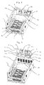
- the fan unit 8 is attached to one end of the housing 2 serving as a fan-unit support member, and includes a fan case 9 and cooling fans 11a, 11b, 11c, 11d, and 11e.
- the fan case 9 is divided into an upper fan case 9a and a lower fan case 9b corresponding to the upper and lower parts of the housing 2.
- the upper fan case 9a and the lower fan case 9b are stacked and fixed to each other with fixing screws 10.
- two cooling fans 11a and 11b are arranged side by side in the right-left direction in the upper fan case 9a
- three fan cases 11c, 11d, and 11e are arranged side by side in the right-left direction in the lower fan case 9b.
- Guides 12a and 12b shaped like flat plates are respectively provided on left and right sides of the upper fan case 9a, and serve to guide attachment and detachment of the fan unit 8.
- the lower fan case 9b has a flange portion 13 to be placed on a portion of the housing 2 having threaded holes.
- This flange portion 13 is provided on the periphery of the lower fan case 9b, and has a plurality of screw passage holes 15 having a diameter larger than the diameter of the heads of the fixing screws 14.
- a fan-unit retainer plate 17 is slidably provided on an upper surface of the flange portion 13 of the lower fan case 9b.
- the fan-unit retainer plate 17 has screw passage holes, for example, keyhole-shaped apertures 16 each defined by a first hole 16a having a diameter smaller than the diameter of the heads of the fixing screws 14 and a second hole 16b having a diameter larger than the diameter of the heads of the fixing screws 14.
- the fan-unit retainer plate 17 has an annular rectangular shape corresponding to the flange portion 13 provided on the periphery of the lower fan case 9b.
- the housing 2 of the inverter apparatus 1 forms the fan-unit support member. At one end of the housing 2 serving as the fan-unit support member, a rectangular opening 18 having a shape corresponding to the shape of the fan unit 8 is provided.
- support members 19a and 19b are provided to fix the guides 12a and 12b provided at the left and right sides of the upper fan case 9a of the fan unit 8.
- the fan-unit retainer plate 17 of the fan unit 8 housed in the inverter apparatus 1 holds the lower fan case 9b down, so that the fan unit 8 is held in the inverter apparatus 1.
- the fan unit 8 is detached from the inverter apparatus 1 in the following manner.
- the fixing screws 14 are loosened sufficiently. In this case, it is unnecessary to completely remove the fixing screws 14.
- the fan-unit retainer plate 17 is slid to the right while being in contact with the lower fan case 9b, and is placed at a position where the large-diameter second holes 16b of the keyhole-shaped apertures 16 provided in the fan-unit retainer plate 17 are aligned with the fixing screws 14, as shown in Fig. 6D .
- the user pulls the fan unit 8 forward while holding a protruding edge 9aa provided in the upper fan case 9a of the fan unit 8, so that the fan unit 8 can be detached from the inverter apparatus 1.
- the fan unit 8 is attached by the reverse procedure.
- the fan unit 8 housed in the inverter apparatus 1 has the above-described configuration, and therefore has the following operational advantages:
- the holes provided in the fan-unit retainer plate 17 are not limited to the keyhole-shaped apertures 16, and for example, may be slots or semicircular holes. In this case, it is also possible to slide the fan-unit retainer plate 17 and to attach and detach the fan unit 8 simply by loosening the fixing screws 14 without completely removing the fixing screws 14.
- a part of the upper fan case 9a forms the guides 12a and 12b shaped like flat plates.
- the guides 12a and 12b are in contact with the support members 19a and 19b of the housing 2 so as to guide attachment and detachment of the fan unit 8.
- the fan unit 8 can be attached and detached easily and reliably.
- an air channel 20 is formed by fixing the guides 12a and 12b to the support members 19a and 19b. This can efficiently cool an adjacent reactor 21 serving as a heating element.
- the inverter apparatus 1 is attached to a control panel or the like (not shown) in a manner such that the fan unit 8 is provided on the upper side and the heat sink 7 is provided on the rear side.
- flange portion 13 is provided in the lower fan case 9b in the above-described embodiment, it may be provided in the upper fan case 9a.
- the present invention can be applied to electronic apparatuses such as an inverter apparatus, a converter apparatus, and a servo amplifier apparatus, and more particularly, to an attachment and detachment structure for a fan unit that forms a cooling device.
Landscapes
- Engineering & Computer Science (AREA)
- Microelectronics & Electronic Packaging (AREA)
- Physics & Mathematics (AREA)
- Thermal Sciences (AREA)
- Cooling Or The Like Of Electrical Apparatus (AREA)
- Inverter Devices (AREA)
Applications Claiming Priority (2)
| Application Number | Priority Date | Filing Date | Title |
|---|---|---|---|
| JP2009122428 | 2009-05-20 | ||
| JP2009267688A JP4662315B2 (ja) | 2009-05-20 | 2009-11-25 | ファンユニットとこれを備えた電子機器装置 |
Publications (3)
| Publication Number | Publication Date |
|---|---|
| EP2254400A2 true EP2254400A2 (de) | 2010-11-24 |
| EP2254400A3 EP2254400A3 (de) | 2011-03-23 |
| EP2254400B1 EP2254400B1 (de) | 2012-05-16 |
Family
ID=42675283
Family Applications (1)
| Application Number | Title | Priority Date | Filing Date |
|---|---|---|---|
| EP10163286A Not-in-force EP2254400B1 (de) | 2009-05-20 | 2010-05-19 | Lüftereinheit und elektronische Vorrichtung damit |
Country Status (3)
| Country | Link |
|---|---|
| US (1) | US8144466B2 (de) |
| EP (1) | EP2254400B1 (de) |
| JP (1) | JP4662315B2 (de) |
Cited By (1)
| Publication number | Priority date | Publication date | Assignee | Title |
|---|---|---|---|---|
| EP3490353A1 (de) * | 2017-11-27 | 2019-05-29 | Siemens Aktiengesellschaft | Kühlsystem mit parallelen kühlkanälen |
Families Citing this family (11)
| Publication number | Priority date | Publication date | Assignee | Title |
|---|---|---|---|---|
| JP5418847B2 (ja) * | 2009-08-04 | 2014-02-19 | 株式会社安川電機 | 電力変換装置 |
| DE102009053583B3 (de) * | 2009-11-17 | 2011-03-31 | Semikron Elektronik Gmbh & Co. Kg | Modular aufgebaute Stromrichteranordnung |
| JP5720977B2 (ja) * | 2010-07-20 | 2015-05-20 | 株式会社安川電機 | マトリクスコンバータ |
| JP5348623B2 (ja) * | 2010-09-10 | 2013-11-20 | 株式会社安川電機 | 電子機器装置 |
| JP5782994B2 (ja) * | 2011-10-31 | 2015-09-24 | 富士電機株式会社 | インバータスタック |
| JP5673857B2 (ja) * | 2011-11-21 | 2015-02-18 | 株式会社オートネットワーク技術研究所 | Dc−dcコンバータ |
| JP6070961B2 (ja) * | 2014-07-29 | 2017-02-01 | 株式会社安川電機 | 電力変換装置及び電力変換システム |
| JP6564339B2 (ja) * | 2016-03-29 | 2019-08-21 | 株式会社日立産機システム | 電力変換装置 |
| CN107134723A (zh) * | 2017-06-28 | 2017-09-05 | 河南森源电气股份有限公司 | 开关柜及其泄压通风装置 |
| JP6613284B2 (ja) * | 2017-10-31 | 2019-11-27 | ファナック株式会社 | ファンユニット |
| US11690195B2 (en) | 2020-09-11 | 2023-06-27 | Abb Schweiz Ag | Power semiconductor cooling system |
Citations (4)
| Publication number | Priority date | Publication date | Assignee | Title |
|---|---|---|---|---|
| US5854738A (en) * | 1997-05-30 | 1998-12-29 | Intel Corporation | Apparatus for supporting a cooling assembly coupled to an integrated circuit |
| JP2000232288A (ja) * | 1999-02-12 | 2000-08-22 | Fuji Electric Co Ltd | 電力変換装置 |
| US20070053160A1 (en) * | 2005-09-07 | 2007-03-08 | Inventec Corporation | Fan bearer |
| US20080107479A1 (en) * | 2006-11-07 | 2008-05-08 | Inventec Corporation | Fan fixing apparatus |
Family Cites Families (14)
| Publication number | Priority date | Publication date | Assignee | Title |
|---|---|---|---|---|
| DE3585447D1 (de) * | 1984-11-15 | 1992-04-02 | Fujitsu Ltd | Kuehlungsstruktur eines gestells fuer elektronische geraete. |
| JP2538709B2 (ja) * | 1990-08-28 | 1996-10-02 | 株式会社ニューギン | パチンコ機における打球発射制御装置 |
| JPH10200280A (ja) * | 1997-01-10 | 1998-07-31 | Sony Corp | 電子機器 |
| TW407741U (en) * | 1998-05-21 | 2000-10-01 | Delta Electronics Inc | Securing device |
| US6392872B1 (en) * | 1999-03-15 | 2002-05-21 | Emc Corporation | Computer system |
| JP3990519B2 (ja) * | 1999-09-30 | 2007-10-17 | 富士通株式会社 | ファンユニット |
| US7019291B2 (en) * | 2002-10-12 | 2006-03-28 | Sionex Corporation | NOx monitor using differential mobility spectrometry |
| US7542272B2 (en) * | 2005-09-30 | 2009-06-02 | Dell Products L.P. | Rotatable cooling fans and method for use |
| US7481704B2 (en) * | 2005-12-12 | 2009-01-27 | Inventec Corporation | Fan rack fixture having two pairs of positioning and locking portions |
| TWI314186B (en) * | 2006-07-24 | 2009-09-01 | Inventec Corp | Fan device |
| JP4775766B2 (ja) | 2006-11-27 | 2011-09-21 | 株式会社安川電機 | モータ制御装置 |
| US20080130217A1 (en) * | 2006-12-05 | 2008-06-05 | Wei-Ping Chen | Swappable data access unit rack structure installable in a computer casing |
| JP4898598B2 (ja) * | 2007-08-28 | 2012-03-14 | 株式会社日立製作所 | ラックマウント型制御装置の冷却構造及びラック型記憶制御装置 |
| US20090116189A1 (en) * | 2007-11-06 | 2009-05-07 | Compucase Enterprise Co., Ltd. (Taiwan) | Cooling System for a Computer Power Supply Unit |
-
2009
- 2009-11-25 JP JP2009267688A patent/JP4662315B2/ja active Active
-
2010
- 2010-05-19 US US12/782,711 patent/US8144466B2/en not_active Expired - Fee Related
- 2010-05-19 EP EP10163286A patent/EP2254400B1/de not_active Not-in-force
Patent Citations (4)
| Publication number | Priority date | Publication date | Assignee | Title |
|---|---|---|---|---|
| US5854738A (en) * | 1997-05-30 | 1998-12-29 | Intel Corporation | Apparatus for supporting a cooling assembly coupled to an integrated circuit |
| JP2000232288A (ja) * | 1999-02-12 | 2000-08-22 | Fuji Electric Co Ltd | 電力変換装置 |
| US20070053160A1 (en) * | 2005-09-07 | 2007-03-08 | Inventec Corporation | Fan bearer |
| US20080107479A1 (en) * | 2006-11-07 | 2008-05-08 | Inventec Corporation | Fan fixing apparatus |
Cited By (3)
| Publication number | Priority date | Publication date | Assignee | Title |
|---|---|---|---|---|
| EP3490353A1 (de) * | 2017-11-27 | 2019-05-29 | Siemens Aktiengesellschaft | Kühlsystem mit parallelen kühlkanälen |
| WO2019101494A1 (de) * | 2017-11-27 | 2019-05-31 | Siemens Aktiengesellschaft | Kühlsystem mit parallelen kühlkanälen |
| US11178798B2 (en) | 2017-11-27 | 2021-11-16 | Siemens Aktiengesellschaft | Cooling system with parallel cooling channels, temperature sensor, and movable flaps |
Also Published As
| Publication number | Publication date |
|---|---|
| US8144466B2 (en) | 2012-03-27 |
| JP4662315B2 (ja) | 2011-03-30 |
| JP2011003872A (ja) | 2011-01-06 |
| US20100296246A1 (en) | 2010-11-25 |
| EP2254400B1 (de) | 2012-05-16 |
| EP2254400A3 (de) | 2011-03-23 |
Similar Documents
| Publication | Publication Date | Title |
|---|---|---|
| EP2254400B1 (de) | Lüftereinheit und elektronische Vorrichtung damit | |
| US7494408B2 (en) | Fan holder | |
| US7688585B2 (en) | Fan mounting apparatus for heat dissipation | |
| US7450379B2 (en) | Heat dissipation device and fan module thereof | |
| US7697302B2 (en) | Mounting apparatus for expansion cards | |
| US20130315728A1 (en) | Fixing device for fan | |
| WO2013110430A1 (de) | Vorrichtung, insbesondere schaltschrank, mit gehäuse | |
| US7545643B2 (en) | Heat dissipation device with a fan duct | |
| US9648789B2 (en) | Apparatus for cooling and mounting a circuit board | |
| US9351420B2 (en) | Systems and methods for manufacturing industrial automation drives | |
| US8315059B2 (en) | Screw less fixing assembly for interface card | |
| US6809922B2 (en) | Expansion card mounting apparatus | |
| US7950446B2 (en) | Heat dissipation device with clip for mounting a fan to a heat sink thereof | |
| EP2456292A1 (de) | Montagevorrichtung für Ventilatoren | |
| CN101892999B (zh) | 风扇单元及具备该单元的电子设备装置 | |
| TW201405013A (zh) | 風扇固定裝置 | |
| US8613595B2 (en) | Fan holder and heat dissipation device using the same | |
| US8142149B2 (en) | Fan device and fan device assembly | |
| US6566597B2 (en) | Shield assembly for computer enclosure and pressing machine for making it | |
| JP2017011201A (ja) | 電力変換装置 | |
| JP5381019B2 (ja) | インバータ装置 | |
| JP5100524B2 (ja) | ファン付ヒートシンク | |
| US20110155345A1 (en) | Mounting apparatus for heat dissipating member | |
| US8553413B2 (en) | Fan mounting apparatus for heat disspation | |
| GB2385468A (en) | Filler panel for computer chassis |
Legal Events
| Date | Code | Title | Description |
|---|---|---|---|
| PUAI | Public reference made under article 153(3) epc to a published international application that has entered the european phase |
Free format text: ORIGINAL CODE: 0009012 |
|
| AK | Designated contracting states |
Kind code of ref document: A2 Designated state(s): AL AT BE BG CH CY CZ DE DK EE ES FI FR GB GR HR HU IE IS IT LI LT LU LV MC MK MT NL NO PL PT RO SE SI SK SM TR |
|
| AX | Request for extension of the european patent |
Extension state: BA ME RS |
|
| PUAL | Search report despatched |
Free format text: ORIGINAL CODE: 0009013 |
|
| AK | Designated contracting states |
Kind code of ref document: A3 Designated state(s): AL AT BE BG CH CY CZ DE DK EE ES FI FR GB GR HR HU IE IS IT LI LT LU LV MC MK MT NL NO PL PT RO SE SI SK SM TR |
|
| AX | Request for extension of the european patent |
Extension state: BA ME RS |
|
| 17P | Request for examination filed |
Effective date: 20110921 |
|
| GRAP | Despatch of communication of intention to grant a patent |
Free format text: ORIGINAL CODE: EPIDOSNIGR1 |
|
| GRAS | Grant fee paid |
Free format text: ORIGINAL CODE: EPIDOSNIGR3 |
|
| GRAA | (expected) grant |
Free format text: ORIGINAL CODE: 0009210 |
|
| AK | Designated contracting states |
Kind code of ref document: B1 Designated state(s): AL AT BE BG CH CY CZ DE DK EE ES FI FR GB GR HR HU IE IS IT LI LT LU LV MC MK MT NL NO PL PT RO SE SI SK SM TR |
|
| REG | Reference to a national code |
Ref country code: GB Ref legal event code: FG4D |
|
| REG | Reference to a national code |
Ref country code: CH Ref legal event code: EP |
|
| REG | Reference to a national code |
Ref country code: AT Ref legal event code: REF Ref document number: 558599 Country of ref document: AT Kind code of ref document: T Effective date: 20120615 |
|
| REG | Reference to a national code |
Ref country code: IE Ref legal event code: FG4D |
|
| REG | Reference to a national code |
Ref country code: DE Ref legal event code: R096 Ref document number: 602010001579 Country of ref document: DE Effective date: 20120712 |
|
| REG | Reference to a national code |
Ref country code: NL Ref legal event code: VDEP Effective date: 20120516 |
|
| REG | Reference to a national code |
Ref country code: LT Ref legal event code: MG4D Effective date: 20120516 |
|
| PG25 | Lapsed in a contracting state [announced via postgrant information from national office to epo] |
Ref country code: PL Free format text: LAPSE BECAUSE OF FAILURE TO SUBMIT A TRANSLATION OF THE DESCRIPTION OR TO PAY THE FEE WITHIN THE PRESCRIBED TIME-LIMIT Effective date: 20120516 Ref country code: CY Free format text: LAPSE BECAUSE OF FAILURE TO SUBMIT A TRANSLATION OF THE DESCRIPTION OR TO PAY THE FEE WITHIN THE PRESCRIBED TIME-LIMIT Effective date: 20120516 Ref country code: FI Free format text: LAPSE BECAUSE OF FAILURE TO SUBMIT A TRANSLATION OF THE DESCRIPTION OR TO PAY THE FEE WITHIN THE PRESCRIBED TIME-LIMIT Effective date: 20120516 Ref country code: NO Free format text: LAPSE BECAUSE OF FAILURE TO SUBMIT A TRANSLATION OF THE DESCRIPTION OR TO PAY THE FEE WITHIN THE PRESCRIBED TIME-LIMIT Effective date: 20120816 Ref country code: IS Free format text: LAPSE BECAUSE OF FAILURE TO SUBMIT A TRANSLATION OF THE DESCRIPTION OR TO PAY THE FEE WITHIN THE PRESCRIBED TIME-LIMIT Effective date: 20120916 Ref country code: LT Free format text: LAPSE BECAUSE OF FAILURE TO SUBMIT A TRANSLATION OF THE DESCRIPTION OR TO PAY THE FEE WITHIN THE PRESCRIBED TIME-LIMIT Effective date: 20120516 Ref country code: SE Free format text: LAPSE BECAUSE OF FAILURE TO SUBMIT A TRANSLATION OF THE DESCRIPTION OR TO PAY THE FEE WITHIN THE PRESCRIBED TIME-LIMIT Effective date: 20120516 |
|
| REG | Reference to a national code |
Ref country code: AT Ref legal event code: MK05 Ref document number: 558599 Country of ref document: AT Kind code of ref document: T Effective date: 20120516 |
|
| PG25 | Lapsed in a contracting state [announced via postgrant information from national office to epo] |
Ref country code: PT Free format text: LAPSE BECAUSE OF FAILURE TO SUBMIT A TRANSLATION OF THE DESCRIPTION OR TO PAY THE FEE WITHIN THE PRESCRIBED TIME-LIMIT Effective date: 20120917 Ref country code: GR Free format text: LAPSE BECAUSE OF FAILURE TO SUBMIT A TRANSLATION OF THE DESCRIPTION OR TO PAY THE FEE WITHIN THE PRESCRIBED TIME-LIMIT Effective date: 20120817 Ref country code: LV Free format text: LAPSE BECAUSE OF FAILURE TO SUBMIT A TRANSLATION OF THE DESCRIPTION OR TO PAY THE FEE WITHIN THE PRESCRIBED TIME-LIMIT Effective date: 20120516 Ref country code: HR Free format text: LAPSE BECAUSE OF FAILURE TO SUBMIT A TRANSLATION OF THE DESCRIPTION OR TO PAY THE FEE WITHIN THE PRESCRIBED TIME-LIMIT Effective date: 20120516 Ref country code: SI Free format text: LAPSE BECAUSE OF FAILURE TO SUBMIT A TRANSLATION OF THE DESCRIPTION OR TO PAY THE FEE WITHIN THE PRESCRIBED TIME-LIMIT Effective date: 20120516 |
|
| PG25 | Lapsed in a contracting state [announced via postgrant information from national office to epo] |
Ref country code: BE Free format text: LAPSE BECAUSE OF FAILURE TO SUBMIT A TRANSLATION OF THE DESCRIPTION OR TO PAY THE FEE WITHIN THE PRESCRIBED TIME-LIMIT Effective date: 20120516 Ref country code: MC Free format text: LAPSE BECAUSE OF NON-PAYMENT OF DUE FEES Effective date: 20120531 |
|
| PG25 | Lapsed in a contracting state [announced via postgrant information from national office to epo] |
Ref country code: AT Free format text: LAPSE BECAUSE OF FAILURE TO SUBMIT A TRANSLATION OF THE DESCRIPTION OR TO PAY THE FEE WITHIN THE PRESCRIBED TIME-LIMIT Effective date: 20120516 Ref country code: DK Free format text: LAPSE BECAUSE OF FAILURE TO SUBMIT A TRANSLATION OF THE DESCRIPTION OR TO PAY THE FEE WITHIN THE PRESCRIBED TIME-LIMIT Effective date: 20120516 Ref country code: NL Free format text: LAPSE BECAUSE OF FAILURE TO SUBMIT A TRANSLATION OF THE DESCRIPTION OR TO PAY THE FEE WITHIN THE PRESCRIBED TIME-LIMIT Effective date: 20120516 Ref country code: CZ Free format text: LAPSE BECAUSE OF FAILURE TO SUBMIT A TRANSLATION OF THE DESCRIPTION OR TO PAY THE FEE WITHIN THE PRESCRIBED TIME-LIMIT Effective date: 20120516 Ref country code: EE Free format text: LAPSE BECAUSE OF FAILURE TO SUBMIT A TRANSLATION OF THE DESCRIPTION OR TO PAY THE FEE WITHIN THE PRESCRIBED TIME-LIMIT Effective date: 20120516 Ref country code: RO Free format text: LAPSE BECAUSE OF FAILURE TO SUBMIT A TRANSLATION OF THE DESCRIPTION OR TO PAY THE FEE WITHIN THE PRESCRIBED TIME-LIMIT Effective date: 20120516 Ref country code: SK Free format text: LAPSE BECAUSE OF FAILURE TO SUBMIT A TRANSLATION OF THE DESCRIPTION OR TO PAY THE FEE WITHIN THE PRESCRIBED TIME-LIMIT Effective date: 20120516 |
|
| REG | Reference to a national code |
Ref country code: IE Ref legal event code: MM4A |
|
| PG25 | Lapsed in a contracting state [announced via postgrant information from national office to epo] |
Ref country code: MK Free format text: LAPSE BECAUSE OF FAILURE TO SUBMIT A TRANSLATION OF THE DESCRIPTION OR TO PAY THE FEE WITHIN THE PRESCRIBED TIME-LIMIT Effective date: 20120516 Ref country code: IT Free format text: LAPSE BECAUSE OF FAILURE TO SUBMIT A TRANSLATION OF THE DESCRIPTION OR TO PAY THE FEE WITHIN THE PRESCRIBED TIME-LIMIT Effective date: 20120516 |
|
| PLBE | No opposition filed within time limit |
Free format text: ORIGINAL CODE: 0009261 |
|
| STAA | Information on the status of an ep patent application or granted ep patent |
Free format text: STATUS: NO OPPOSITION FILED WITHIN TIME LIMIT |
|
| 26N | No opposition filed |
Effective date: 20130219 |
|
| PG25 | Lapsed in a contracting state [announced via postgrant information from national office to epo] |
Ref country code: ES Free format text: LAPSE BECAUSE OF FAILURE TO SUBMIT A TRANSLATION OF THE DESCRIPTION OR TO PAY THE FEE WITHIN THE PRESCRIBED TIME-LIMIT Effective date: 20120827 Ref country code: IE Free format text: LAPSE BECAUSE OF NON-PAYMENT OF DUE FEES Effective date: 20120519 |
|
| REG | Reference to a national code |
Ref country code: DE Ref legal event code: R097 Ref document number: 602010001579 Country of ref document: DE Effective date: 20130219 |
|
| PG25 | Lapsed in a contracting state [announced via postgrant information from national office to epo] |
Ref country code: MT Free format text: LAPSE BECAUSE OF FAILURE TO SUBMIT A TRANSLATION OF THE DESCRIPTION OR TO PAY THE FEE WITHIN THE PRESCRIBED TIME-LIMIT Effective date: 20120516 Ref country code: BG Free format text: LAPSE BECAUSE OF FAILURE TO SUBMIT A TRANSLATION OF THE DESCRIPTION OR TO PAY THE FEE WITHIN THE PRESCRIBED TIME-LIMIT Effective date: 20120816 |
|
| PG25 | Lapsed in a contracting state [announced via postgrant information from national office to epo] |
Ref country code: AL Free format text: LAPSE BECAUSE OF FAILURE TO SUBMIT A TRANSLATION OF THE DESCRIPTION OR TO PAY THE FEE WITHIN THE PRESCRIBED TIME-LIMIT Effective date: 20120516 |
|
| PG25 | Lapsed in a contracting state [announced via postgrant information from national office to epo] |
Ref country code: TR Free format text: LAPSE BECAUSE OF FAILURE TO SUBMIT A TRANSLATION OF THE DESCRIPTION OR TO PAY THE FEE WITHIN THE PRESCRIBED TIME-LIMIT Effective date: 20120516 |
|
| PG25 | Lapsed in a contracting state [announced via postgrant information from national office to epo] |
Ref country code: SM Free format text: LAPSE BECAUSE OF FAILURE TO SUBMIT A TRANSLATION OF THE DESCRIPTION OR TO PAY THE FEE WITHIN THE PRESCRIBED TIME-LIMIT Effective date: 20120516 Ref country code: LU Free format text: LAPSE BECAUSE OF NON-PAYMENT OF DUE FEES Effective date: 20120519 |
|
| PG25 | Lapsed in a contracting state [announced via postgrant information from national office to epo] |
Ref country code: HU Free format text: LAPSE BECAUSE OF FAILURE TO SUBMIT A TRANSLATION OF THE DESCRIPTION OR TO PAY THE FEE WITHIN THE PRESCRIBED TIME-LIMIT Effective date: 20100519 |
|
| REG | Reference to a national code |
Ref country code: CH Ref legal event code: PL |
|
| PG25 | Lapsed in a contracting state [announced via postgrant information from national office to epo] |
Ref country code: LI Free format text: LAPSE BECAUSE OF NON-PAYMENT OF DUE FEES Effective date: 20140531 Ref country code: CH Free format text: LAPSE BECAUSE OF NON-PAYMENT OF DUE FEES Effective date: 20140531 |
|
| REG | Reference to a national code |
Ref country code: FR Ref legal event code: PLFP Year of fee payment: 7 |
|
| PGFP | Annual fee paid to national office [announced via postgrant information from national office to epo] |
Ref country code: GB Payment date: 20160601 Year of fee payment: 7 Ref country code: DE Payment date: 20160531 Year of fee payment: 7 |
|
| PGFP | Annual fee paid to national office [announced via postgrant information from national office to epo] |
Ref country code: FR Payment date: 20160524 Year of fee payment: 7 |
|
| REG | Reference to a national code |
Ref country code: DE Ref legal event code: R119 Ref document number: 602010001579 Country of ref document: DE |
|
| GBPC | Gb: european patent ceased through non-payment of renewal fee |
Effective date: 20170519 |
|
| REG | Reference to a national code |
Ref country code: FR Ref legal event code: ST Effective date: 20180131 |
|
| PG25 | Lapsed in a contracting state [announced via postgrant information from national office to epo] |
Ref country code: DE Free format text: LAPSE BECAUSE OF NON-PAYMENT OF DUE FEES Effective date: 20171201 Ref country code: GB Free format text: LAPSE BECAUSE OF NON-PAYMENT OF DUE FEES Effective date: 20170519 |
|
| PG25 | Lapsed in a contracting state [announced via postgrant information from national office to epo] |
Ref country code: FR Free format text: LAPSE BECAUSE OF NON-PAYMENT OF DUE FEES Effective date: 20170531 |