EP2253858A1 - Karabinerhaken mit wenigstens einer rutschfesten Zone - Google Patents
Karabinerhaken mit wenigstens einer rutschfesten Zone Download PDFInfo
- Publication number
- EP2253858A1 EP2253858A1 EP10001915A EP10001915A EP2253858A1 EP 2253858 A1 EP2253858 A1 EP 2253858A1 EP 10001915 A EP10001915 A EP 10001915A EP 10001915 A EP10001915 A EP 10001915A EP 2253858 A1 EP2253858 A1 EP 2253858A1
- Authority
- EP
- European Patent Office
- Prior art keywords
- hook
- slip
- closure part
- hook body
- slip zone
- Prior art date
- Legal status (The legal status is an assumption and is not a legal conclusion. Google has not performed a legal analysis and makes no representation as to the accuracy of the status listed.)
- Granted
Links
Images

Classifications
-
- A—HUMAN NECESSITIES
- A63—SPORTS; GAMES; AMUSEMENTS
- A63B—APPARATUS FOR PHYSICAL TRAINING, GYMNASTICS, SWIMMING, CLIMBING, OR FENCING; BALL GAMES; TRAINING EQUIPMENT
- A63B29/00—Apparatus for mountaineering
-
- F—MECHANICAL ENGINEERING; LIGHTING; HEATING; WEAPONS; BLASTING
- F16—ENGINEERING ELEMENTS AND UNITS; GENERAL MEASURES FOR PRODUCING AND MAINTAINING EFFECTIVE FUNCTIONING OF MACHINES OR INSTALLATIONS; THERMAL INSULATION IN GENERAL
- F16B—DEVICES FOR FASTENING OR SECURING CONSTRUCTIONAL ELEMENTS OR MACHINE PARTS TOGETHER, e.g. NAILS, BOLTS, CIRCLIPS, CLAMPS, CLIPS OR WEDGES; JOINTS OR JOINTING
- F16B45/00—Hooks; Eyes
- F16B45/02—Hooks with pivoting or elastically bending closing member
- F16B45/023—Hooks with pivoting or elastically bending closing member the closing member pivoting about an axis perpendicular to the plane of the hook
-
- F—MECHANICAL ENGINEERING; LIGHTING; HEATING; WEAPONS; BLASTING
- F16—ENGINEERING ELEMENTS AND UNITS; GENERAL MEASURES FOR PRODUCING AND MAINTAINING EFFECTIVE FUNCTIONING OF MACHINES OR INSTALLATIONS; THERMAL INSULATION IN GENERAL
- F16B—DEVICES FOR FASTENING OR SECURING CONSTRUCTIONAL ELEMENTS OR MACHINE PARTS TOGETHER, e.g. NAILS, BOLTS, CIRCLIPS, CLAMPS, CLIPS OR WEDGES; JOINTS OR JOINTING
- F16B45/00—Hooks; Eyes
- F16B45/02—Hooks with pivoting or elastically bending closing member
- F16B45/027—Hooks with pivoting or elastically bending closing member and having position-locking means for the closing member
- F16B45/028—Hooks with pivoting or elastically bending closing member and having position-locking means for the closing member the position-locking means being pivotally connected
Definitions
- the invention relates to a snap hook according to the preamble of claim 1.
- Such a snap hook is known from practice.
- a snap hook is made of metal, in particular aluminum.
- the handling of the known snap hook is difficult because the hand catching the hook can easily slip on the material of the snap hook.
- At high temperatures there is also a risk of burns, a risk of chilling in the event of severe frost and the risk of freezing of body parts on the snap hook.
- a wet snap hook can quickly slip away in a mountain rescue operation of the mountain climber's hand, which can cause serious problems for life and limb of the climber.
- the invention has for its object to provide a snap hook of the type mentioned, which is easier to handle even in adverse weather.
- hook body, closure part and / or a fuse for the closure part are at least partially non-slip.
- the snap hook according to the invention even in bad weather, such as heavy rain, be taken and covered safely.
- the closure part can be opened more easily and a rope can be inserted through the insertion opening of the hook body into the snap hook.
- the snap hook according to the invention is easier and, above all, safer to handle.
- hook body, closure member and / or fuse on its outer side at least one non-slip zone.
- the non-slip zone has an inhibiting effect so that the user's hand can grasp and grasp the snap hook more easily.
- a movement along the relevant part of the snap hook is decelerated by the at least one non-slip zone.
- the grip of the snap hook is significantly improved.
- the at least one non-slip zone made of a non-slip material, preferably made of rubber, sandpaper, or the like.
- the entire carabiner hook is made of this handy material. It is therefore also possible, for example, to retrofit existing snap hooks with the non-slip material.
- the snap hook according to the invention may be made of metal, with only the at least one non-slip zone of the said material to be manufactured or formed.
- the material of the at least one non-slip zone is colored opposite that of the hook body, the closure part and / or the fuse.
- the material of the at least one non-slip zone is a good heat insulator. This ensures that the snap hook according to the invention even under extreme conditions, such as high heat or extreme frost, is relatively easy to handle and for the aforementioned reasons, a risk of injury is significantly reduced.
- the at least one non-slip zone is applied to the hook body, the closure part and / or the fuse, preferably sprayed or sprayed on or glued or glued.
- the at least one non-slip zone can also be subsequently fixed to a snap hook.
- Such application of the non-slip zone on parts of the hook can be done quickly and relatively inexpensively. There is good adhesion between the at least one non-slip zone and the relevant part of the snap hook.
- hook body, closure part and / or fuse on a recess for receiving the at least one non-slip zone As a result, the at least one non-slip zone is securely held on the relevant part of the carabiner hook. It can therefore be less easily removed from the relevant part of the snap hook. Unintentional removal of at least one non-slip zone of the snap hook is almost impossible.
- the at least one non-slip zone is cup-shaped and the hook body, the closure part and / or the fuse formed and arranged at least partially encompassing.
- the at least one non-slip zone is fastened very securely to the relevant part of the carabiner hook.
- the relevant part of the snap hook protected by such trained at least one non-slip zone, so that wear of the relevant part of the snap hook can occur less easily.
- the bowl-shaped design of the at least one non-slip zone also facilitates recognition of the zone from the side, since the at least one non-slip zone can be readily recognized from three different viewing directions.
- the at least one non-slip zone is strip-shaped.
- Such an alternative to the embodiment described above is particularly inexpensive to produce and can be made almost independent of the shape of the respective snap hook.
- Fig. 1 is a schematic front view of a snap hook 1 shown in a first embodiment.
- the snap hook 1 has a hook body 2, which has a head part 3 with a free hook end 4, a base part 5 and an insertion opening 6 formed between the base part 5 and the free hook end 4. The latter is more accurate in the FIGS. 2 and 3 shown.
- snap hook 1 Construction and shape of the snap hook 1 can vary in many ways. So are those in the Fig. 1 to 6 shown snap hooks 1 shown only by way of example and in no way limiting.
- the snap hook 1 therefore has the hook body 2 with the insertion opening 6. Furthermore, the hook body 2 has a closure part 7, which optionally overlaps the insertion opening 6. This position is in the Fig. 1 and 4 and 5 are shown.
- the closure part 7 is pivotally mounted on the base part 5 of the hook body 2.
- the one end 10 of the closure part 7 receives the pivot axis 11; the opposite other end, hereinafter called the free end 12 of the closure part 7, is in the in the Fig. 1 . 4 and 5 shown closed position of the closure part 7 with the free hook end 4 of the hook body 2 positively connected.
- the closure part 7 is out of his in Fig. 1 shown closed position in his example in the FIGS.
- FIGS. 2 and 3 shown release position and vice versa.
- a transfer of the closure part 7 from the closed position according to Fig. 1 in the release position according to Fig. 2 takes place in the direction of arrow A in Fig. 1
- a usually automatic transfer of the closure part 7 from the release position according to Fig. 2 in the closed position of the closure part 7 according to Fig. 1 takes place in the direction of arrow B in Fig. 2
- the positive connection between the free hook end 4 of the hook body 2 and the other, free end 12 of the closure part 7 is in the illustration of FIGS. 2 and 3 omitted for simplicity.
- the snap hook 1 also has a schematically only indicated, L-shaped fuse 13. This is pivotally mounted about a pivot axis 14 on the hook body 2.
- the fuse 13 has a locking bar 15, which in Fig. 4 is merely indicated. This allows a transfer of the closure part 7 from the closed position to the release position only when the fuse 13 together with its locking bolt 15 from a in Fig. 4 shown locking position is pivoted in the direction of arrow C in an unlocking position not shown in detail.
- the closure part 7 in Fig. 4 in the direction of arrow A from its illustrated closed position in the example in the FIGS. 2 and 3 indicated release position to be pivoted.
- hook body 2, closure member 7 and / or fuse 13 for the closure part 7 are at least partially non-slip.
- hook body 2, closure part 7 and / or securing device 13 have on their outside 16 at least one non-slip zone 17.
- hook body 2 and closure member 7 are each provided with a non-slip zone 17.
- hook body 2 and closure member 7 are grippy, each with a non-slip zone 17 is formed, whereas in the in the 4 and 5 shown embodiment, the fuse 13, the non-slip zone 17 has.
- the non-slip zone 17 extends over a respective length of the hook body, the closure part or the fuse.
- the at least one non-slip zone 17 is made of a non-slip material, such as rubber, sandpaper or the like. This material, from which the at least one non-slip zone 17 is made, is colored according to a preferred embodiment of the invention compared to the material of the hook body 2, the closure part 7 and / or the fuse 13 discontinued. According to a particularly preferred embodiment of the invention, the material is the least one non-slip zone 17 a good heat insulator, such as a plastic with a low thermal conductivity.
- the at least one non-slip zone 17 is applied to the hook body 2, the closure part 7 and / or the fuse 13, wherein this application can be effected by means of injection molding, spraying, gluing or gluing.
- the hook body, closure part and / or securing feature a recess 20 for receiving the at least one non-slip zone 17.
- hook body 2 and closure part 7 have such a recess 20; at the in the 4 and 5 shown embodiment of the invention, such is formed on the fuse 13.
- the recesses 20 are slight recesses, which are preferably adapted to the shape of the non-slip zone 17, so that the top 21 of the non-slip zone with the outside 16 of the hook body 2, the closure part 7 and the fuse 13 is aligned, as in Fig. 1 is shown.
- the non-slip zone 17 on its upper side 21 transversely to the longitudinal axis of the non-slip zone 17 extending grooves 22, wherein also in this embodiment, the top 21 of the non-slip zone 17 is aligned with the outside 16 of the fuse.
- the at least one non-slip zone 17 is strip-shaped, as shown in FIGS FIGS. 2 and 3 is shown schematically.
- a non-slip zone can also be formed as a coating of the non-slip zone-carrying part, that is, for example, the hook body, the closure part or the fuse.
- the non-slip zones are shown in this embodiment of the invention as a dotted area.
- the at least one non-slip zone 17 is cup-shaped and the hook body 2, the closure part 7 and / or the securing device 13 are formed and arranged at least partially encompassing each other. This is for those in the 4 and 5 shown embodiment in more detail in the exploded, perspective view of Fig. 6 shown. In the in Fig. 6 shown illustration of the fuse 13 whose locking bolt 15 is omitted for simplicity.
- the snap hook according to the invention allows a better grip, since parts of the carabiner hook embracing hand of the user does not lie on the material of the snap hook, such as bare metal, and do not come into contact with this.
- the snap hook may have one or more non-slip zones.
- the arrangement of the non-slip zones is not on the in the Fig. 1 to 6 shown limited arrangement.
Landscapes
- Engineering & Computer Science (AREA)
- General Engineering & Computer Science (AREA)
- Mechanical Engineering (AREA)
- Health & Medical Sciences (AREA)
- Pulmonology (AREA)
- General Health & Medical Sciences (AREA)
- Physical Education & Sports Medicine (AREA)
- Hooks, Suction Cups, And Attachment By Adhesive Means (AREA)
Abstract
Description
- Die Erfindung bezieht sich auf einen Karabinerhaken nach dem Oberbegriff des Anspruchs 1.
- Ein solcher Karabinerhaken ist aus der Praxis bekannt. Üblicherweise ist ein derartiger Karabinerhaken aus Metall, insbesondere Aluminium, gefertigt. Unter schwierigen Einsatzbedingungen, wie zum Beispiel bei ungünstiger Witterung durch Schnee, Regen, Kälte, Hitze, ist die Handhabung des bekannten Karabinerhakens erschwert, da die den Haken ergreifende Hand leicht am Material des Karabinerhakens abrutschen kann. Bei großer Hitze besteht ferner Verbrennungsgefahr, bei starkem Frost Auskühlungsgefahr sowie Gefahr des Festfrierens von Körperteilen an dem Karabinerhaken. Insbesondere ein feuchter Karabinerhaken kann in einem Bergeinsatz der Hand des Bergsteigers schnell entgleiten, was gravierende Probleme für Leib und Leben des Bergsteigers nach sich ziehen kann.
- Der Erfindung liegt die Aufgabe zugrunde, einen Karabinerhaken der eingangs erwähnten Art zu schaffen, der auch bei ungünstiger Witterung leichter handhabbar ist.
- Diese Aufgabe wird erfindungsgemäß durch einen Karabinerhaken mit den Merkmalen des Anspruchs 1 gelöst.
- Vorteilhafte Weiterbildungen sind Gegenstand der Unteransprüche.
- Erfindungsgemäß sind Hakenkörper, Verschlussteil und/oder eine Sicherung für das Verschlussteil zumindest teilweise rutschfest ausgebildet. Dadurch kann der erfindungsgemäße Karabinerhaken auch bei schlechter Witterung, wie zum Beispiel starkem Regen, sicher ergriffen und umfasst werden. Zudem kann das Verschlussteil leichter geöffnet und ein Seil durch die Einführöffnung des Hakenkörpers in den Karabinerhaken eingeführt werden. Dadurch ist der erfindungsgemäße Karabinerhaken leichter und vor allem auch sicherer handhabbar.
- Vorteilhafterweise weisen Hakenkörper, Verschlussteil und/oder Sicherung auf ihrer Außenseite wenigstens eine rutschfeste Zone auf. Die rutschfeste Zone wirkt hemmend, so dass die Hand des Benutzers den Karabinerhaken leichter ergreifen und umfassen kann. Eine Bewegung entlang des betreffenden Teils des Karabinerhakens wird durch die wenigstens eine rutschfeste Zone abgebremst. Die Griffigkeit des Karabinerhakens ist deutlich verbessert.
- Gemäß einer anderen Weiterbildung der Erfindung ist die wenigstens eine rutschfeste Zone aus einem griffigen Material, vorzugsweise aus Gummi, Sandpapier, oder dergleichen, hergestellt. Insofern ist nicht der gesamte Karabinerhaken aus diesem griffigen Material zu fertigen. Es ist daher beispielsweise auch möglich, bestehende Karabinerhaken mit dem griffigen Material nachzurüsten. Auch aus Festigkeitsgründen kann der erfindungsgemäße Karabinerhaken aus Metall gefertigt sein, wobei lediglich die wenigstens eine rutschfeste Zone aus dem genannten Material zu fertigen bzw. gebildet ist.
- Gemäß einer anderen Weiterbildung der Erfindung ist das Material der wenigstens einen rutschfesten Zone farblich gegenüber demjenigen des Hakenkörpers, des Verschlussteils und/oder der Sicherung abgesetzt. Dies hat den Vorteil, dass der Benutzer des erfindungsgemäßen Karabinerhakens sogleich erkennen kann, an welcher Stelle der Karabinerhaken vorteilhaft, nämlich rutschfest, ergriffen oder umfasst werden kann. Auch durch dieses Merkmal ist die Handhabbarkeit des erfindungsgemäßen Karabinerhakens verbessert. Besondere Vorteile hat die farbliche Absetzung in den Fällen, in denen ein Anfassen des Karabinerhakens an anderen als an den rutschfesten Stellen besonders gefährlich sein kann, wie zum Beispiel bei großer Hitze oder extremer Kälte.
- Gemäß einer besonders bevorzugten Ausführungsform der Erfindung ist das Material der wenigstens einen rutschfesten Zone ein guter Wärmeisolator. Dadurch ist sichergestellt, dass der erfindungsgemäße Karabinerhaken auch unter Extrembedingungen, wie zum Beispiel großer Hitze oder extremem Frost, relativ gut handhabbar ist und aus den vorgenannten Gründen eine Verletzungsgefahr deutlich vermindert ist.
- Vorteilhafterweise ist die wenigstens eine rutschfeste Zone auf den Hakenkörper, das Verschlussteil und/oder die Sicherung aufgebracht, vorzugsweise an- oder aufgespritzt oder an- oder aufgeklebt. Insofern kann die wenigstens eine rutschfeste Zone auch nachträglich an einem Karabinerhaken fixiert werden. Ein derartiges Aufbringen der rutschfesten Zone auf Teile des Hakens kann schnell und verhältnismäßig kostengünstig erfolgen. Es besteht eine gute Haftung zwischen der wenigstens einen rutschfesten Zone und dem betreffenden Teil des Karabinerhakens.
- Gemäß einer anderen Weiterbildung der Erfindung weisen Hakenkörper, Verschlussteil und/oder Sicherung eine Ausnehmung zum Aufnehmen der wenigstens einen rutschfesten Zone auf. Dadurch ist die wenigstens eine rutschfeste Zone sicher am betreffenden Teil des Karabinerhakens gehalten. Sie kann dadurch weniger leicht von dem betreffenden Teil des Karabinerhakens entfernt werden. Ein unabsichtliches Abziehen der wenigstens einen rutschfesten Zone von dem Karabinerhaken ist nahezu ausgeschlossen.
- Gemäß einer vorteilhaften Weiterbildung ist die wenigstens eine rutschfeste Zone schalenförmig und den Hakenkörper, das Verschlussteil und/oder die Sicherung zumindest teilweise umgreifend ausgebildet und angeordnet. Dadurch ist die wenigstens eine rutschfeste Zone sehr sicher am betreffenden Teil des Karabinerhakens befestigt. Zudem ist das betreffende Teil des Karabinerhakens durch eine derart ausgebildete wenigstens eine rutschfeste Zone geschützt, so dass ein Verschleiß des betreffenden Teils des Karabinerhakens weniger leicht auftreten kann. Die schalenförmige Ausbildung der wenigstens einen rutschfesten Zone erleichtert ein Erkennen der Zone auch von der Seite her, da quasi aus drei verschiedenen Blickrichtungen die wenigstens eine rutschfeste Zone ohne weiteres erkennbar ist.
- Vorteilhafterweise ist die wenigstens eine rutschfeste Zone streifenförmig ausgebildet. Eine solche Alternative zu der zuvor beschriebenen Ausführungsform ist besonders kostengünstig herstellbar und kann nahezu unabhängig von der Form des jeweiligen Karabinerhakens gefertigt werden.
- Ausführungsformen des Erfindungsgegenstandes werden nachfolgend anhand der Zeichnung näher erläutert, wobei alle beschriebenen und/oder bildlich dargestellten Merkmale für sich oder in beliebiger Kombination den Gegenstand der vorliegenden Erfindung unabhängig von ihrer Zusammenfassung in den Ansprüchen oder deren Rückbeziehung bilden. Es zeigen:
-
Fig. 1 eine schematische Vorderansicht eines Karabinerhakens gemäß einer ersten Ausführungsform; -
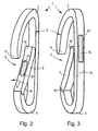
Fig. 2 eine schematische, vereinfachte, perspektivische Ansicht eines Karabinerhakens gemäß einer zweiten Ausführungsform; -
Fig. 3 eine schematische, vereinfachte, perspektivische Ansicht des Karabinerhakens gemäßFig. 2 von einer rückseitigen Perspektive her; -
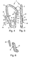
Fig. 4 eine schematische Vorderansicht eines Karabinerhakens gemäß einer dritten Ausführungsform; -
Fig. 5 eine schematische Seitenansicht des Karabinerhakens gemäßFig. 4 ; und -
Fig. 6 eine schematische, perspektivische Teilansicht einer Sicherung des Karabinerhakens gemäß denFig. 4 und 5 . - In
Fig. 1 ist eine schematische Vorderansicht eines Karabinerhakens 1 in einer ersten Ausführungsform dargestellt. Der Karabinerhaken 1 hat einen Hakenkörper 2, welcher ein Kopfteil 3 mit einem freien Hakenende 4, ein Basisteil 5 und eine zwischen dem Basisteil 5 und dem freien Hakenende 4 ausgebildete Einführöffnung 6 aufweist. Letztere ist genauer in denFig. 2 und 3 gezeigt. - Aufbau und Form des Karabinerhakens 1 können in vielfältiger Weise variieren. So sind die in den
Fig. 1 bis 6 gezeigten Karabinerhaken 1 lediglich beispielhaft und in keiner Weise beschränkend dargestellt. - Der Karabinerhaken 1 hat daher den Hakenkörper 2 mit der Einführöffnung 6. Ferner hat der Hakenkörper 2 ein Verschlussteil 7, das die Einführöffnung 6 wahlweise übergreift. Diese Stellung ist in den
Fig. 1 sowie 4 und 5 gezeigt. Bei den dargestellten Ausführungsformen des Karabinerhakens 1 ist das Verschlussteil 7 schwenkbar am Basisteil 5 des Hakenkörpers 2 gelagert. Das eine Ende 10 des Verschlussteils 7 nimmt die Schwenkachse 11 auf; das gegenüber liegende andere Ende, nachfolgend freies Ende 12 des Verschlussteils 7 genannt, ist in der in denFig. 1 ,4 und 5 gezeigten Schließstellung des Verschlussteils 7 mit dem freien Hakenende 4 des Hakenkörpers 2 formschlüssig verbindbar. Insofern ist das Verschlussteil 7 aus seiner inFig. 1 gezeigten Schließstellung in seine beispielhaft in denFig. 2 und 3 gezeigte Freigabestellung und umgekehrt überführbar. Ein Überführen des Verschlussteils 7 aus der Schließstellung gemäßFig. 1 in die Freigabestellung gemäßFig. 2 erfolgt also in Richtung des Pfeils A inFig. 1 . Ein üblicherweise selbsttätiges Überführen des Verschlussteils 7 aus der Freigabestellung gemäßFig. 2 in die Schließstellung des Verschlussteils 7 gemäßFig. 1 erfolgt in Richtung des Pfeils B inFig. 2 . Die formschlüssige Verbindung zwischen dem freien Hakenende 4 des Hakenkörpers 2 und dem anderen, freien Ende 12 des Verschlussteils 7 ist in der Darstellung derFig. 2 und 3 der Einfachheit halber weggelassen. - Gemäß einer genauer in den
Fig. 4 und 5 gezeigten Ausführungsform der Erfindung hat der Karabinerhaken 1 ferner eine schematisch lediglich angedeutete, L-förmige Sicherung 13. Diese ist um eine Schwenkachse 14 schwenkbar am Hakenkörper 2 gelagert. Die Sicherung 13 hat einen Sperrriegel 15, welcher inFig. 4 lediglich angedeutet ist. Dieser ermöglicht ein Überführen des Verschlussteils 7 aus der Schließstellung in die Freigabestellung nur dann, wenn die Sicherung 13 zusammen mit ihrem Sperrriegel 15 aus einer inFig. 4 gezeigten Verriegelungsstellung in Richtung des Pfeils C in eine nicht näher gezeigte Entriegelungsstellung verschwenkt ist. In der nicht näher gezeigten Entriegelungsstellung des Sperrriegels 15 kann das Verschlussteil 7 inFig. 4 in Richtung des Pfeils A aus seiner dargestellten Schließstellung in die beispielhaft in denFig. 2 und 3 angedeutete Freigabestellung verschwenkt werden. - Erfindungsgemäß sind Hakenkörper 2, Verschlussteil 7 und/oder Sicherung 13 für das Verschlussteil 7 zumindest teilweise rutschfest ausgebildet. Dazu weisen Hakenkörper 2, Verschlussteil 7 und/oder Sicherung 13 auf ihrer Außenseite 16 wenigstens eine rutschfeste Zone 17 auf.
- In der in
Fig. 1 gezeigten Ausführungsform sind Hakenkörper 2 und Verschlussteil 7 jeweils mit einer rutschfesten Zone 17 versehen. Bei der in denFig. 2 und 3 gezeigten Ausführungsform sind ebenfalls Hakenkörper 2 und Verschlussteil 7 griffig mit jeweils einer rutschfesten Zone 17 ausgebildet, wohingegen bei der in denFig. 4 und 5 gezeigten Ausführungsform die Sicherung 13 die rutschfeste Zone 17 aufweist. - Die rutschfeste Zone 17 erstreckt sich jeweils über einen Längenabschnitt des Hakenkörpers, des Verschlussteils bzw. der Sicherung. Die wenigstens eine rutschfeste Zone 17 ist aus einem griffigen Material, beispielsweise aus Gummi, Sandpapier oder dergleichen, hergestellt. Dieses Material, aus dem die wenigstens eine rutschfeste Zone 17 gefertigt ist, ist gemäß einer bevorzugten Ausführungsform der Erfindung farblich gegenüber dem Material des Hakenkörpers 2, des Verschlussteils 7 und/oder der Sicherung 13 abgesetzt. Gemäß einer besonders bevorzugten Ausführungsform der Erfindung ist das Material der wenigsten einen rutschfesten Zone 17 ein guter Wärmeisolator, wie zum Beispiel ein Kunststoff mit einer geringen Wärmeleitfähigkeit.
- Die wenigstens eine rutschfeste Zone 17 ist auf den Hakenkörper 2, das Verschlussteil 7 und/oder die Sicherung 13 aufgebracht, wobei dieses Aufbringen mittels Anspritzen, Aufspritzen, Ankleben oder Aufkleben erfolgen kann.
- Gemäß einer bevorzugten Ausführungsform der Erfindung weisen Hakenkörper, Verschlussteil und/oder Sicherung eine Ausnehmung 20 zum Aufnehmen der wenigstens einen rutschfesten Zone 17 auf. Bei der in
Fig. 1 gezeigten Ausführungsform der Erfindung haben Hakenkörper 2 und Verschlussteil 7 eine solche Ausnehmung 20; bei der in denFig. 4 und 5 gezeigten Ausführungsform der Erfindung ist eine solche an der Sicherung 13 ausgebildet. - Die Ausnehmungen 20 sind leichte Vertiefungen, welche vorzugsweise an die Form der rutschfesten Zone 17 angepasst sind, so dass die Oberseite 21 der rutschfesten Zone mit der Außenseite 16 des Hakenkörpers 2, des Verschlussteils 7 bzw. der Sicherung 13 fluchtet, wie dies in
Fig. 1 gezeigt ist. - Bei der in den
Fig. 4 und 5 gezeigten Ausführungsform der Erfindung hat die rutschfeste Zone 17 auf ihrer Oberseite 21 quer zur Längsachse der rutschfesten Zone 17 sich erstreckende Rillen 22, wobei auch bei dieser Ausführungsform die Oberseite 21 der rutschfesten Zone 17 mit der Außenseite 16 der Sicherung fluchtet. - Gemäß einer vereinfachten Ausführungsform der Erfindung ist die wenigstens eine rutschfeste Zone 17 streifenförmig ausgebildet, wie dies in den
Fig. 2 und 3 schematisch dargestellt ist. Eine solche rutschfeste Zone kann auch als Beschichtung des die rutschfeste Zone tragenden Teils, also beispielsweise des Hakenkörpers, des Verschlussteils bzw. der Sicherung, ausgebildet sein. Die rutschfesten Zonen sind bei dieser Ausführungsform der Erfindung als gepunktete Fläche dargestellt. - Bei den in den
Fig. 1 ,4 bis 6 gezeigten Ausführungsformen ist die wenigstens eine rutschfeste Zone 17 schalenförmig und den Hakenkörper 2, das Verschlussteil 7 und/oder die Sicherung 13 zumindest teilweise umgreifend ausgebildet und angeordnet. Dies ist für die in denFig. 4 und 5 gezeigte Ausführungsform genauer in der auseinander gezogenen, perspektivischen Ansicht derFig. 6 dargestellt. In der inFig. 6 gezeigten Darstellung der Sicherung 13 ist dessen Sperrriegel 15 der Einfachheit halber weggelassen. - Insofern ermöglicht der erfindungsgemäße Karabinerhaken einen besseren Griff, da Teile der den Karabinerhaken umgreifenden Hand des Benutzers nicht auf dem Material des Karabinerhakens, wie zum Beispiel blankem Metall, zu liegen und nicht mit diesem in Berührung kommen. Der Karabinerhaken kann eine oder mehrere rutschfeste Zonen aufweisen. Die Anordnung der rutschfesten Zonen ist nicht auf die in den
Fig. 1 bis 6 gezeigte Anordnung beschränkt. So ist es möglich, am Hakenkörper 2 mehrere rutschfeste Zonen vorzusehen oder die gesamte Außenfläche des Hakenkörpers als rutschfeste Zone auszubilden. - Somit ist ein Karabinerhaken geschaffen, der in sämtlichen praktischen Einsatzfällen und somit auch bei ungünstiger Witterung leichter und sicherer handhabbar ist.
Claims (9)
- Karabinerhaken,
mit einem eine Einführöffnung (6) aufweisenden Hakenkörper (2) und
mit einem die Einführöffnung (6) des Hakenkörpers (2) wahlweise übergreifenden Verschlussteil (7),
dadurch gekennzeichnet,
dass Hakenkörper (2), Verschlussteil (7) und/oder eine Sicherung (13) für das Verschlussteil 7 zumindest teilweise rutschfest ausgebildet sind. - Karabinerhaken nach Anspruch 1, dadurch gekennzeichnet, dass Hakenkörper (2), Verschlussteil (7) und/oder Sicherung (13) auf ihrer Außenseite (16) wenigstens eine rutschfeste Zone (17) aufweisen.
- Karabinerhaken nach Anspruch 2, dadurch gekennzeichnet, dass die wenigstens eine rutschfeste Zone (17) aus einem griffigen Material, vorzugsweise aus Gummi, Sandpapier oder dergleichen, hergestellt ist.
- Karabinerhaken nach Anspruch 3, dadurch gekennzeichnet, dass das Material der wenigstens einen rutschfesten Zone (17) farblich gegenüber demjenigen des Hakenkörpers (2), des Verschlussteils (7) und/oder der Sicherung (13) abgesetzt ist.
- Karabinerhaken nach Anspruch 3 oder 4, dadurch gekennzeichnet, dass das Material der wenigstens einen rutschfesten Zone (17) ein guter Wärmeisolator ist.
- Karabinerhaken nach einem der Ansprüche 2 bis 5, dadurch gekennzeichnet, dass die wenigstens eine rutschfeste Zone (17) auf den Hakenkörpers (2), das Verschlussteil (7) und/oder die Sicherung (13) aufgebracht, vorzugsweise an- oder aufgespritzt oder an- oder aufgeklebt, ist.
- Karabinerhaken nach einem der Ansprüche 2 bis 6, dadurch gekennzeichnet, dass Hakenkörper (2), Verschlussteil (7) und/oder Sicherung (13) eine Ausnehmung (20) zum Aufnehmen der wenigstens einen rutschfesten Zone (17) aufweisen.
- Karabinerhaken nach einem der Ansprüche 2 bis 7, dadurch gekennzeichnet, dass die wenigstens eine rutschfeste Zone (17) schalenförmig und den Hakenkörper (2), das Verschlussteil (7) und/oder die Sicherung (13) zumindest teilweise umgreifend ausgebildet und angeordnet ist.
- Karabinerhaken nach einem der Ansprüche 2 bis 7, dadurch gekennzeichnet, dass die wenigstens eine rutschfeste Zone (17) streifenförmig ausgebildet ist.
Applications Claiming Priority (1)
| Application Number | Priority Date | Filing Date | Title |
|---|---|---|---|
| DE202009006894U DE202009006894U1 (de) | 2009-05-14 | 2009-05-14 | Karabinerhaken mit wenigstens einer rutschfesten Zone |
Publications (2)
| Publication Number | Publication Date |
|---|---|
| EP2253858A1 true EP2253858A1 (de) | 2010-11-24 |
| EP2253858B1 EP2253858B1 (de) | 2014-11-26 |
Family
ID=42063318
Family Applications (1)
| Application Number | Title | Priority Date | Filing Date |
|---|---|---|---|
| EP10001915.7A Active EP2253858B1 (de) | 2009-05-14 | 2010-02-24 | Karabinerhaken mit wenigstens einer rutschfesten Zone |
Country Status (2)
| Country | Link |
|---|---|
| EP (1) | EP2253858B1 (de) |
| DE (1) | DE202009006894U1 (de) |
Cited By (2)
| Publication number | Priority date | Publication date | Assignee | Title |
|---|---|---|---|---|
| EP3148383A4 (de) * | 2014-06-02 | 2018-01-17 | Norén, Per | Vorrichtung zur unterstützung des ausziehens und anziehens eines kleidungsstücks |
| CN107920635A (zh) * | 2015-07-21 | 2018-04-17 | 旅行凯帝公司 | 互锁拉链拉片及紧固系统 |
Citations (5)
| Publication number | Priority date | Publication date | Assignee | Title |
|---|---|---|---|---|
| DE9208862U1 (de) * | 1992-07-02 | 1993-08-19 | vauDe Sport Albrecht von Dewitz, 88069 Tettnang | Karabinerhaken |
| US20040036303A1 (en) * | 2002-08-20 | 2004-02-26 | Luggage America, Inc. | Dual locking hook |
| US20060168781A1 (en) * | 2001-05-31 | 2006-08-03 | Wendy Axel | Handle with grip for comfortably holding articles by hand |
| US7181809B1 (en) * | 2006-02-28 | 2007-02-27 | Su-Min Kuo | Stretch cord hook |
| US20070050956A1 (en) * | 2005-09-06 | 2007-03-08 | Bobby Hu | Apparatus for carrying tools |
Family Cites Families (4)
| Publication number | Priority date | Publication date | Assignee | Title |
|---|---|---|---|---|
| FR2628801B3 (fr) * | 1988-03-18 | 1990-07-13 | Hurel Dubois Avions | Dispositif pour assurer le pivotement elastique d'une piece mobile par rapport a une piece fixe, applicable notamment a la realisation de boucles d'accrochage du type mousqueton |
| DE9110358U1 (de) * | 1991-08-22 | 1991-11-28 | Henssgen Karabinerhaken GmbH, 5603 Wülfrath | Karabinerhaken |
| FR2898506B1 (fr) * | 2006-03-15 | 2008-05-30 | Zedel Soc Par Actions Simplifi | Appareil multifonctionnel d'assurage pour corde |
| FR2920498B1 (fr) * | 2007-08-31 | 2009-11-27 | Zedel | Mousqueton a doigt pivotant equipe d'une bague de verrouillage |
-
2009
- 2009-05-14 DE DE202009006894U patent/DE202009006894U1/de not_active Expired - Lifetime
-
2010
- 2010-02-24 EP EP10001915.7A patent/EP2253858B1/de active Active
Patent Citations (5)
| Publication number | Priority date | Publication date | Assignee | Title |
|---|---|---|---|---|
| DE9208862U1 (de) * | 1992-07-02 | 1993-08-19 | vauDe Sport Albrecht von Dewitz, 88069 Tettnang | Karabinerhaken |
| US20060168781A1 (en) * | 2001-05-31 | 2006-08-03 | Wendy Axel | Handle with grip for comfortably holding articles by hand |
| US20040036303A1 (en) * | 2002-08-20 | 2004-02-26 | Luggage America, Inc. | Dual locking hook |
| US20070050956A1 (en) * | 2005-09-06 | 2007-03-08 | Bobby Hu | Apparatus for carrying tools |
| US7181809B1 (en) * | 2006-02-28 | 2007-02-27 | Su-Min Kuo | Stretch cord hook |
Cited By (2)
| Publication number | Priority date | Publication date | Assignee | Title |
|---|---|---|---|---|
| EP3148383A4 (de) * | 2014-06-02 | 2018-01-17 | Norén, Per | Vorrichtung zur unterstützung des ausziehens und anziehens eines kleidungsstücks |
| CN107920635A (zh) * | 2015-07-21 | 2018-04-17 | 旅行凯帝公司 | 互锁拉链拉片及紧固系统 |
Also Published As
| Publication number | Publication date |
|---|---|
| EP2253858B1 (de) | 2014-11-26 |
| DE202009006894U1 (de) | 2010-04-01 |
Similar Documents
| Publication | Publication Date | Title |
|---|---|---|
| EP2849603B1 (de) | Stockgriff mit geführter schlaufe | |
| EP3248497B1 (de) | Handhaltevorrichtung insbesondere handschuh zur befestigung an einem stockgriff | |
| EP3214965B1 (de) | Langlauf-stockgriff | |
| DE2610041A1 (de) | Skibindung | |
| WO2011113739A1 (de) | Stockgriff | |
| DE29904591U1 (de) | Stockgriff mit Handschlaufe | |
| DE3314099C2 (de) | ||
| WO1999052608A1 (de) | Snowboard-einsteigbindung | |
| EP2253858B1 (de) | Karabinerhaken mit wenigstens einer rutschfesten Zone | |
| DE602004004260T2 (de) | Sperrvorrichtung für Schneeketten | |
| DE69917149T2 (de) | Gleitbrett für Alpineski oder Snowboarding | |
| DE602005002092T2 (de) | Textiler Gleitschutzüberzug für Fahrzeugreifen | |
| EP0830185B1 (de) | Anordnung einer langlauf-, insbesondere skating-bindung | |
| DE2801615C2 (de) | Vorrichtung zum Zusammenhalten eines Skipaares | |
| DE102017120688A1 (de) | Bindung mit Sicherungselement für Skibremse | |
| DE7039190U (de) | Skibremse | |
| DE102007013643B4 (de) | Zugentlastung eines Kabels für ein elektromotorisch betriebenes, handgeführtes Arbeitsgerät | |
| DE8008624U1 (de) | Vorrichtung zum Verbinden der Griff einrichtung bei Windsurfern | |
| DE9317567U1 (de) | Diebstahlsicherung von Skiern und Skistöcken | |
| DE1703234C3 (de) | Auslöse vorderstrammer einer Skibindung. Ausscheidung aus: 1428997 | |
| WO1984002063A1 (fr) | Outil pour skis et chaussures de ski | |
| DE60206949T2 (de) | Verbindungs- und Spanneinrichtung für Schneeketten | |
| DE60121723T2 (de) | Gleitschutzkette mit abnehmbarer Verlängerung zur Vereinfachung des Anbaus und Verlängerung dafür | |
| DE20108512U1 (de) | Karabinerhaken | |
| DE7412359U (de) | Ski |
Legal Events
| Date | Code | Title | Description |
|---|---|---|---|
| PUAI | Public reference made under article 153(3) epc to a published international application that has entered the european phase |
Free format text: ORIGINAL CODE: 0009012 |
|
| AK | Designated contracting states |
Kind code of ref document: A1 Designated state(s): AT BE BG CH CY CZ DE DK EE ES FI FR GB GR HR HU IE IS IT LI LT LU LV MC MK MT NL NO PL PT RO SE SI SK SM TR |
|
| AX | Request for extension of the european patent |
Extension state: AL BA RS |
|
| 17P | Request for examination filed |
Effective date: 20110418 |
|
| 17Q | First examination report despatched |
Effective date: 20140107 |
|
| GRAP | Despatch of communication of intention to grant a patent |
Free format text: ORIGINAL CODE: EPIDOSNIGR1 |
|
| INTG | Intention to grant announced |
Effective date: 20140813 |
|
| GRAS | Grant fee paid |
Free format text: ORIGINAL CODE: EPIDOSNIGR3 |
|
| GRAA | (expected) grant |
Free format text: ORIGINAL CODE: 0009210 |
|
| AK | Designated contracting states |
Kind code of ref document: B1 Designated state(s): AT BE BG CH CY CZ DE DK EE ES FI FR GB GR HR HU IE IS IT LI LT LU LV MC MK MT NL NO PL PT RO SE SI SK SM TR |
|
| REG | Reference to a national code |
Ref country code: GB Ref legal event code: FG4D Free format text: NOT ENGLISH |
|
| REG | Reference to a national code |
Ref country code: CH Ref legal event code: EP |
|
| REG | Reference to a national code |
Ref country code: AT Ref legal event code: REF Ref document number: 698385 Country of ref document: AT Kind code of ref document: T Effective date: 20141215 Ref country code: CH Ref legal event code: NV Representative=s name: GACHNANG AG PATENTANWAELTE, CH |
|
| REG | Reference to a national code |
Ref country code: IE Ref legal event code: FG4D Free format text: LANGUAGE OF EP DOCUMENT: GERMAN |
|
| REG | Reference to a national code |
Ref country code: DE Ref legal event code: R096 Ref document number: 502010008324 Country of ref document: DE Effective date: 20150108 |
|
| REG | Reference to a national code |
Ref country code: NL Ref legal event code: VDEP Effective date: 20141126 |
|
| REG | Reference to a national code |
Ref country code: LT Ref legal event code: MG4D |
|
| PG25 | Lapsed in a contracting state [announced via postgrant information from national office to epo] |
Ref country code: NO Free format text: LAPSE BECAUSE OF FAILURE TO SUBMIT A TRANSLATION OF THE DESCRIPTION OR TO PAY THE FEE WITHIN THE PRESCRIBED TIME-LIMIT Effective date: 20150226 Ref country code: IS Free format text: LAPSE BECAUSE OF FAILURE TO SUBMIT A TRANSLATION OF THE DESCRIPTION OR TO PAY THE FEE WITHIN THE PRESCRIBED TIME-LIMIT Effective date: 20150326 Ref country code: PT Free format text: LAPSE BECAUSE OF FAILURE TO SUBMIT A TRANSLATION OF THE DESCRIPTION OR TO PAY THE FEE WITHIN THE PRESCRIBED TIME-LIMIT Effective date: 20150326 Ref country code: NL Free format text: LAPSE BECAUSE OF FAILURE TO SUBMIT A TRANSLATION OF THE DESCRIPTION OR TO PAY THE FEE WITHIN THE PRESCRIBED TIME-LIMIT Effective date: 20141126 Ref country code: LT Free format text: LAPSE BECAUSE OF FAILURE TO SUBMIT A TRANSLATION OF THE DESCRIPTION OR TO PAY THE FEE WITHIN THE PRESCRIBED TIME-LIMIT Effective date: 20141126 Ref country code: ES Free format text: LAPSE BECAUSE OF FAILURE TO SUBMIT A TRANSLATION OF THE DESCRIPTION OR TO PAY THE FEE WITHIN THE PRESCRIBED TIME-LIMIT Effective date: 20141126 Ref country code: FI Free format text: LAPSE BECAUSE OF FAILURE TO SUBMIT A TRANSLATION OF THE DESCRIPTION OR TO PAY THE FEE WITHIN THE PRESCRIBED TIME-LIMIT Effective date: 20141126 |
|
| PG25 | Lapsed in a contracting state [announced via postgrant information from national office to epo] |
Ref country code: CY Free format text: LAPSE BECAUSE OF FAILURE TO SUBMIT A TRANSLATION OF THE DESCRIPTION OR TO PAY THE FEE WITHIN THE PRESCRIBED TIME-LIMIT Effective date: 20141126 Ref country code: GR Free format text: LAPSE BECAUSE OF FAILURE TO SUBMIT A TRANSLATION OF THE DESCRIPTION OR TO PAY THE FEE WITHIN THE PRESCRIBED TIME-LIMIT Effective date: 20150227 Ref country code: SE Free format text: LAPSE BECAUSE OF FAILURE TO SUBMIT A TRANSLATION OF THE DESCRIPTION OR TO PAY THE FEE WITHIN THE PRESCRIBED TIME-LIMIT Effective date: 20141126 Ref country code: HR Free format text: LAPSE BECAUSE OF FAILURE TO SUBMIT A TRANSLATION OF THE DESCRIPTION OR TO PAY THE FEE WITHIN THE PRESCRIBED TIME-LIMIT Effective date: 20141126 Ref country code: LV Free format text: LAPSE BECAUSE OF FAILURE TO SUBMIT A TRANSLATION OF THE DESCRIPTION OR TO PAY THE FEE WITHIN THE PRESCRIBED TIME-LIMIT Effective date: 20141126 |
|
| PG25 | Lapsed in a contracting state [announced via postgrant information from national office to epo] |
Ref country code: CZ Free format text: LAPSE BECAUSE OF FAILURE TO SUBMIT A TRANSLATION OF THE DESCRIPTION OR TO PAY THE FEE WITHIN THE PRESCRIBED TIME-LIMIT Effective date: 20141126 Ref country code: SK Free format text: LAPSE BECAUSE OF FAILURE TO SUBMIT A TRANSLATION OF THE DESCRIPTION OR TO PAY THE FEE WITHIN THE PRESCRIBED TIME-LIMIT Effective date: 20141126 Ref country code: EE Free format text: LAPSE BECAUSE OF FAILURE TO SUBMIT A TRANSLATION OF THE DESCRIPTION OR TO PAY THE FEE WITHIN THE PRESCRIBED TIME-LIMIT Effective date: 20141126 Ref country code: RO Free format text: LAPSE BECAUSE OF FAILURE TO SUBMIT A TRANSLATION OF THE DESCRIPTION OR TO PAY THE FEE WITHIN THE PRESCRIBED TIME-LIMIT Effective date: 20141126 Ref country code: DK Free format text: LAPSE BECAUSE OF FAILURE TO SUBMIT A TRANSLATION OF THE DESCRIPTION OR TO PAY THE FEE WITHIN THE PRESCRIBED TIME-LIMIT Effective date: 20141126 |
|
| REG | Reference to a national code |
Ref country code: DE Ref legal event code: R097 Ref document number: 502010008324 Country of ref document: DE |
|
| PG25 | Lapsed in a contracting state [announced via postgrant information from national office to epo] |
Ref country code: PL Free format text: LAPSE BECAUSE OF FAILURE TO SUBMIT A TRANSLATION OF THE DESCRIPTION OR TO PAY THE FEE WITHIN THE PRESCRIBED TIME-LIMIT Effective date: 20141126 |
|
| PG25 | Lapsed in a contracting state [announced via postgrant information from national office to epo] |
Ref country code: LU Free format text: LAPSE BECAUSE OF FAILURE TO SUBMIT A TRANSLATION OF THE DESCRIPTION OR TO PAY THE FEE WITHIN THE PRESCRIBED TIME-LIMIT Effective date: 20150224 |
|
| PLBE | No opposition filed within time limit |
Free format text: ORIGINAL CODE: 0009261 |
|
| STAA | Information on the status of an ep patent application or granted ep patent |
Free format text: STATUS: NO OPPOSITION FILED WITHIN TIME LIMIT |
|
| GBPC | Gb: european patent ceased through non-payment of renewal fee |
Effective date: 20150226 |
|
| PG25 | Lapsed in a contracting state [announced via postgrant information from national office to epo] |
Ref country code: MC Free format text: LAPSE BECAUSE OF FAILURE TO SUBMIT A TRANSLATION OF THE DESCRIPTION OR TO PAY THE FEE WITHIN THE PRESCRIBED TIME-LIMIT Effective date: 20141126 |
|
| 26N | No opposition filed |
Effective date: 20150827 |
|
| REG | Reference to a national code |
Ref country code: IE Ref legal event code: MM4A |
|
| PG25 | Lapsed in a contracting state [announced via postgrant information from national office to epo] |
Ref country code: IT Free format text: LAPSE BECAUSE OF FAILURE TO SUBMIT A TRANSLATION OF THE DESCRIPTION OR TO PAY THE FEE WITHIN THE PRESCRIBED TIME-LIMIT Effective date: 20141126 |
|
| PG25 | Lapsed in a contracting state [announced via postgrant information from national office to epo] |
Ref country code: GB Free format text: LAPSE BECAUSE OF NON-PAYMENT OF DUE FEES Effective date: 20150226 Ref country code: IE Free format text: LAPSE BECAUSE OF NON-PAYMENT OF DUE FEES Effective date: 20150224 |
|
| REG | Reference to a national code |
Ref country code: FR Ref legal event code: PLFP Year of fee payment: 7 |
|
| PG25 | Lapsed in a contracting state [announced via postgrant information from national office to epo] |
Ref country code: SI Free format text: LAPSE BECAUSE OF FAILURE TO SUBMIT A TRANSLATION OF THE DESCRIPTION OR TO PAY THE FEE WITHIN THE PRESCRIBED TIME-LIMIT Effective date: 20141126 |
|
| PG25 | Lapsed in a contracting state [announced via postgrant information from national office to epo] |
Ref country code: MT Free format text: LAPSE BECAUSE OF FAILURE TO SUBMIT A TRANSLATION OF THE DESCRIPTION OR TO PAY THE FEE WITHIN THE PRESCRIBED TIME-LIMIT Effective date: 20141126 |
|
| REG | Reference to a national code |
Ref country code: FR Ref legal event code: PLFP Year of fee payment: 8 |
|
| PG25 | Lapsed in a contracting state [announced via postgrant information from national office to epo] |
Ref country code: SM Free format text: LAPSE BECAUSE OF FAILURE TO SUBMIT A TRANSLATION OF THE DESCRIPTION OR TO PAY THE FEE WITHIN THE PRESCRIBED TIME-LIMIT Effective date: 20141126 Ref country code: HU Free format text: LAPSE BECAUSE OF FAILURE TO SUBMIT A TRANSLATION OF THE DESCRIPTION OR TO PAY THE FEE WITHIN THE PRESCRIBED TIME-LIMIT; INVALID AB INITIO Effective date: 20100224 Ref country code: BG Free format text: LAPSE BECAUSE OF FAILURE TO SUBMIT A TRANSLATION OF THE DESCRIPTION OR TO PAY THE FEE WITHIN THE PRESCRIBED TIME-LIMIT Effective date: 20141126 |
|
| PG25 | Lapsed in a contracting state [announced via postgrant information from national office to epo] |
Ref country code: BE Free format text: LAPSE BECAUSE OF NON-PAYMENT OF DUE FEES Effective date: 20150228 |
|
| PG25 | Lapsed in a contracting state [announced via postgrant information from national office to epo] |
Ref country code: TR Free format text: LAPSE BECAUSE OF FAILURE TO SUBMIT A TRANSLATION OF THE DESCRIPTION OR TO PAY THE FEE WITHIN THE PRESCRIBED TIME-LIMIT Effective date: 20141126 |
|
| REG | Reference to a national code |
Ref country code: FR Ref legal event code: PLFP Year of fee payment: 9 |
|
| PG25 | Lapsed in a contracting state [announced via postgrant information from national office to epo] |
Ref country code: MK Free format text: LAPSE BECAUSE OF FAILURE TO SUBMIT A TRANSLATION OF THE DESCRIPTION OR TO PAY THE FEE WITHIN THE PRESCRIBED TIME-LIMIT Effective date: 20141126 |
|
| REG | Reference to a national code |
Ref country code: DE Ref legal event code: R082 Ref document number: 502010008324 Country of ref document: DE Representative=s name: KANDLBINDER, MARKUS, DIPL.-PHYS., DE |
|
| REG | Reference to a national code |
Ref country code: CH Ref legal event code: PK Free format text: BERICHTIGUNGEN |
|
| PGFP | Annual fee paid to national office [announced via postgrant information from national office to epo] |
Ref country code: DE Payment date: 20250429 Year of fee payment: 16 |
|
| REG | Reference to a national code |
Ref country code: CH Ref legal event code: U11 Free format text: ST27 STATUS EVENT CODE: U-0-0-U10-U11 (AS PROVIDED BY THE NATIONAL OFFICE) Effective date: 20260301 |
|
| PGFP | Annual fee paid to national office [announced via postgrant information from national office to epo] |
Ref country code: AT Payment date: 20260216 Year of fee payment: 17 |
|
| PGFP | Annual fee paid to national office [announced via postgrant information from national office to epo] |
Ref country code: FR Payment date: 20260219 Year of fee payment: 17 |
|
| PGFP | Annual fee paid to national office [announced via postgrant information from national office to epo] |
Ref country code: CH Payment date: 20260301 Year of fee payment: 17 |