EP2253494A1 - Belüftungseinrichtung für eine Fahrerkabine eines Kraftfahrzeugs - Google Patents
Belüftungseinrichtung für eine Fahrerkabine eines Kraftfahrzeugs Download PDFInfo
- Publication number
- EP2253494A1 EP2253494A1 EP10162566A EP10162566A EP2253494A1 EP 2253494 A1 EP2253494 A1 EP 2253494A1 EP 10162566 A EP10162566 A EP 10162566A EP 10162566 A EP10162566 A EP 10162566A EP 2253494 A1 EP2253494 A1 EP 2253494A1
- Authority
- EP
- European Patent Office
- Prior art keywords
- fresh air
- ventilation device
- determined
- cabin
- driver
- Prior art date
- Legal status (The legal status is an assumption and is not a legal conclusion. Google has not performed a legal analysis and makes no representation as to the accuracy of the status listed.)
- Granted
Links
- 238000009423 ventilation Methods 0.000 title claims description 34
- 238000010438 heat treatment Methods 0.000 claims description 26
- 238000004378 air conditioning Methods 0.000 claims description 11
- 238000011144 upstream manufacturing Methods 0.000 claims description 10
- 238000005276 aerator Methods 0.000 abstract 1
- 239000000203 mixture Substances 0.000 abstract 1
- 238000000034 method Methods 0.000 description 19
- 239000003507 refrigerant Substances 0.000 description 16
- 239000002826 coolant Substances 0.000 description 14
- 238000011156 evaluation Methods 0.000 description 5
- 238000001816 cooling Methods 0.000 description 4
- 239000000356 contaminant Substances 0.000 description 3
- 230000002528 anti-freeze Effects 0.000 description 2
- 238000002485 combustion reaction Methods 0.000 description 2
- 230000006837 decompression Effects 0.000 description 2
- 230000006735 deficit Effects 0.000 description 2
- 150000002430 hydrocarbons Chemical class 0.000 description 2
- 239000007788 liquid Substances 0.000 description 2
- XLYOFNOQVPJJNP-UHFFFAOYSA-N water Substances O XLYOFNOQVPJJNP-UHFFFAOYSA-N 0.000 description 2
- 230000003213 activating effect Effects 0.000 description 1
- 238000005273 aeration Methods 0.000 description 1
- 230000007423 decrease Effects 0.000 description 1
- 230000001419 dependent effect Effects 0.000 description 1
- 239000004459 forage Substances 0.000 description 1
- 230000000977 initiatory effect Effects 0.000 description 1
- 230000003287 optical effect Effects 0.000 description 1
- 230000035699 permeability Effects 0.000 description 1
- 230000003134 recirculating effect Effects 0.000 description 1
- 230000000007 visual effect Effects 0.000 description 1
Images

Classifications
-
- B—PERFORMING OPERATIONS; TRANSPORTING
- B60—VEHICLES IN GENERAL
- B60H—ARRANGEMENTS OF HEATING, COOLING, VENTILATING OR OTHER AIR-TREATING DEVICES SPECIALLY ADAPTED FOR PASSENGER OR GOODS SPACES OF VEHICLES
- B60H1/00—Heating, cooling or ventilating [HVAC] devices
- B60H1/00357—Air-conditioning arrangements specially adapted for particular vehicles
- B60H1/00378—Air-conditioning arrangements specially adapted for particular vehicles for tractor or load vehicle cabins
-
- B—PERFORMING OPERATIONS; TRANSPORTING
- B60—VEHICLES IN GENERAL
- B60H—ARRANGEMENTS OF HEATING, COOLING, VENTILATING OR OTHER AIR-TREATING DEVICES SPECIALLY ADAPTED FOR PASSENGER OR GOODS SPACES OF VEHICLES
- B60H1/00—Heating, cooling or ventilating [HVAC] devices
- B60H1/00642—Control systems or circuits; Control members or indication devices for heating, cooling or ventilating devices
- B60H1/00735—Control systems or circuits characterised by their input, i.e. by the detection, measurement or calculation of particular conditions, e.g. signal treatment, dynamic models
- B60H1/00792—Arrangement of detectors
-
- B—PERFORMING OPERATIONS; TRANSPORTING
- B60—VEHICLES IN GENERAL
- B60H—ARRANGEMENTS OF HEATING, COOLING, VENTILATING OR OTHER AIR-TREATING DEVICES SPECIALLY ADAPTED FOR PASSENGER OR GOODS SPACES OF VEHICLES
- B60H1/00—Heating, cooling or ventilating [HVAC] devices
- B60H1/00642—Control systems or circuits; Control members or indication devices for heating, cooling or ventilating devices
- B60H1/00814—Control systems or circuits characterised by their output, for controlling particular components of the heating, cooling or ventilating installation
- B60H1/00821—Control systems or circuits characterised by their output, for controlling particular components of the heating, cooling or ventilating installation the components being ventilating, air admitting or air distributing devices
- B60H1/00828—Ventilators, e.g. speed control
Definitions
- the invention relates to a ventilation device for a driver's cab of a motor vehicle, with a circulating air blower for generating a circulating air flow acting on the driver's cab.
- Such a ventilation device for a cab of an agricultural vehicle is from the EP 125 562 A1 out.
- the known ventilation device comprises a circulating air blower for generating a recirculating air flow, for which cabin air is drawn in by means of the circulating air blower and returned to the driver's cab after passing through an air conditioning device consisting of an evaporator and a heating coil.
- a mixing chamber upstream of the air conditioning device is used for the admixture of fresh air, which is sucked in by means of an auxiliary blower outside the driver's cab.
- the known ventilation device provides for continuous operation of the auxiliary blower with a speed to be set by the driver.
- An auxiliary blower upstream filter element is used to clean the fresh air sucked. Since the surface of the filter element is contaminated with contaminants during use, and consequently its permeability decreases over time, the driver is forced to manually adjust the speed of the auxiliary blower to ensure consistent cabin air quality.
- the ventilation device for a driver's cab of a motor vehicle comprises a circulating air blower for generating a circulating air flow which acts on the driver's cab.
- a circulating air blower for generating a circulating air flow which acts on the driver's cab.
- fresh air sucked in by means of an auxiliary blower is added to the circulating air flow in such a way that a determined cabin internal pressure and / or a determined fresh air volume flow does not fall below a respective predetermined minimum value.
- the specification of the minimum values can be made according to objective criteria, for example according to legal guidelines.
- EN 15695-1 for cabs of categories 3 and 4 a cabin internal pressure of at least 20 Pa and a fresh air volume flow of at least 30 cbm / h.
- the ventilation device can have a pressure sensor arranged inside the driver's cab which provides a pressure signal representing the cabin internal pressure. Furthermore, a flow sensor may be provided for determining the fresh air volume flow. The latter provides a volume flow signal representing the fresh air volume flow. Both signals are fed to a control device for evaluation. The control device controls the auxiliary blower on the basis of the signals such that the for the cabin internal pressure and / or the fresh air volume flow each predetermined minimum value is not fallen below.
- the ventilation device For admixing the fresh air, the ventilation device comprises a mixing chamber through which the circulating air stream flows, which has a fresh air inlet connected to the auxiliary blower.
- the fresh air inlet may in particular be provided with an adjustable inlet flap, which allows influencing the admixed fresh air quantity by changing the inlet cross section.
- the mixing chamber is preferably connected upstream of the circulating air blower on the low pressure side, so that a particularly uniform admixture of the fresh air is ensured.
- the admixing of the fresh air can take place in accordance with a comparison between the determined cabin internal pressure and the minimum value predetermined for the cabin internal pressure and / or between the determined fresh air volume flow and the minimum value predetermined for the fresh air volume flow.
- the admixed amount of fresh air can be increased if it results on the basis of the comparison that the determined cabin internal pressure and / or the determined fresh air volume flow falls below the respective predetermined minimum value.
- the admixture the fresh air take place in such a way that the determined cabin internal pressure and / or the determined fresh air volume flow reaches a reference value which is higher than the respective predetermined minimum value.
- the circulating air flow can be tempered by means of an air conditioning device, wherein the admixture of the fresh air takes place in accordance with a determined cabin interior temperature.
- the ventilation device may have a temperature sensor arranged inside the driver's cab. The temperature sensor provides a cabin temperature representative temperature signal, which is supplied to the control device for evaluation.
- the admixed amount of fresh air is reduced if it appears that the determined cabin interior temperature deviates by more than a permissible difference from a predetermined desired value.
- the reduction is preferably carried out such that the determined cabin internal pressure and / or the determined fresh air volume flow occupies the respective predetermined minimum value.
- the admixing of untemperierter fresh air takes place only to the extent that this is absolutely necessary to maintain the minimum values predetermined for the cabin internal pressure and / or the fresh air volume flow.
- the requirements for the cooling or heating power to be provided by the air conditioning device can be reduced in this way without having to put up with any impairment of the cabin air quality.
- the speed of the auxiliary blower can be changed. More specifically, the auxiliary blower on an electric motor drive, by means of which can be put on a drive shaft mounted fan rotor in rotation. To change the speed of the fan rotor and thus the amount of fresh air delivered, the electromotive drive can be controlled via an intermediate speed controller by the control device in accordance with the comparison between the determined cabin internal pressure and the predetermined minimum value for the cabin interior pressure and / or the determined fresh air volume flow and the predetermined for the fresh air volume flow Control minimum value.
- the fan rotor of the auxiliary blower it is also possible for the fan rotor of the auxiliary blower to have adjustable conveying wings. In this case, the auxiliary fan can be operated at a constant speed, wherein the admixture of fresh air can be influenced only by changing the position of the sash.
- the air-conditioning device for controlling the temperature of the circulating air flow and the admixed fresh air may comprise an evaporator and / or a heating element.
- the evaporator is in particular part of a refrigerant circuit, in addition to the evaporator, a compressor for compressing a refrigerant circulating in the refrigerant circuit, an air-flow condenser for liquefying the compressed refrigerant, a liquid separator for separating the liquefied refrigerant, and a decompression valve upstream of the evaporator in the circulation direction of the refrigerant For expanding the liquefied refrigerant.
- the refrigerant is, for example, CO 2 or a suitable hydrocarbon compound.
- the heating element may be part of a coolant circuit for cooling an internal combustion engine located in the motor vehicle, wherein the coolant circuit has a coolant pump for conveying a coolant circulating in the coolant circuit and an air-flowed radiator in addition to the heating element designed as a heating heat exchanger.
- the coolant is usually water, which is mixed with a suitable antifreeze.
- the heating element is connected downstream of the evaporator in the direction of the circulating air flow in such a way that the proportion of air flowing through the heating element and thus the temperature of the circulating air flow can be influenced by adjusting a deflecting flap assigned to the heating element.
- the heating element can in this case structurally adjoin the evaporator directly.
- the adjustment of the heating power takes place here by controlling the amount of coolant passing through the heating heat exchanger. If it is an electrically operated heating element, then the heating power depends on the electrical current consumption of a heating coil encompassed by the heating element.
- the circulation fan and / or the auxiliary fan is preferably designed as a radial fan.
- the radial fan has an oriented in the direction of its drive axis air intake, wherein the sucked air is deflected and blown radially to the drive axle. An undesirable access of contaminants in the ventilation device can be avoided if the circulating air blower and / or the auxiliary blower upstream of a filter element is connected upstream.
- the filter element is, for example, a zigzag folded filter fleece.
- the pressure drop occurring when the driver's cab is opened can lead to the minimum value specified for the cabin interior pressure being undershot.
- a closable cab opening in particular a driver door provided with a car door, is not closed. Whether this is the case can be recognized by evaluating the actuation state of a contact switch connected to the control device and provided for determining the closed state of the cabin opening.
- the output of a driver information can be made when the cabin opening is not closed.
- a generation of suitable visual and / or acoustic warning signals is conceivable.
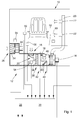
- Fig. 1 shows an embodiment of the ventilation device according to the invention for a driver's cab of a motor vehicle.
- the motor vehicle is in particular a non-illustrated agricultural utility vehicle, for example, a tractor, a harvester, a forage harvester or the like. Notwithstanding this, however, the ventilating device according to the invention can also be used with any other motor vehicle with the driver's cab closed.
- the ventilation device 12 provided for the air conditioning of the driver's cab 10 comprises a circulating-air blower 14 and a mixing chamber 16 which is connected upstream of the circulating-air blower 14 on the low-pressure side and communicates with an air inlet opening 18.
- the latter is formed in the present case in the floor area of the cab 10.
- the air inlet opening 18 can also be arranged at any other point of the driver's cab 10, for example, distributed over a plurality of inlet openings in the region of an interior trim surrounding the driver's seat at the rear.
- the circulating-air blower 14 is connected on the high-pressure side to an air-distributing system 20 which opens into the driver's cab 10.
- the air distribution system 20 has a plurality of distributed in the cab 10 air outlet openings 22.
- Each of the air outlet openings 22 may be provided with an adjustable louver aperture for influencing the direction of the circulating air flow exiting into the driver's cab 10.
- An auxiliary blower 24 connected to the mixing chamber 16 on the high pressure side serves to supply fresh air, which is sucked in via an air inlet opening 26 arranged on the outside of the driver's cab 10 and mixed with the circulating air flow via a fresh air inlet 28 formed in the mixing chamber 16.
- the rotational speed of the circulating air blower 14 or of the auxiliary blower 24 can be changed. More precisely, the circulating air blower 14 or the auxiliary blower 24 has an electromotive drive, by means of which a fan rotor mounted on a drive axle can be set in rotation. To change the speed of the fan rotor and thus the amount of air delivered, the electric motor drive via an intermediate speed controller 28 by a control device 30 can be controlled.
- both the circulation fan 14 and the auxiliary fan 24 is formed as a radial fan.
- Each of the radial fans has an oriented in the direction of its drive axis Air intake, wherein the sucked air is deflected and blown radially to the drive axis.
- the filter element 32 and 34 In order to avoid unwanted access of contaminants in the ventilation device 12, the circulating air blower 14 and the auxiliary blower 24 on the suction side, a filter element 32 and 34 connected upstream.
- the filter element 32 or 34 is a zigzag-folded filter fleece which is part of an exchangeable filter cassette.
- an air conditioning device 36 is arranged in the mixing chamber 16.
- the air conditioning device 36 comprises an evaporator 38 and / or a heating element 40.
- the evaporator 38 is part of a refrigerant circuit 42, in addition to the evaporator 38 further, for clarity, not shown components, in particular a compressor for compressing a circulating in the refrigerant circuit 42 refrigerant, an air-flowed condenser for liquefying the compressed refrigerant, a liquid separator for separating the Liquefied refrigerant and a the evaporator 38 upstream in the direction of circulation of the refrigerant decompression valve for expanding the liquefied refrigerant.
- the refrigerant is, for example, CO 2 or a suitable hydrocarbon compound.
- the heating element 40 is part of a coolant circuit 44 for cooling an internal combustion engine located in the motor vehicle.
- the coolant circuit 44 has, in addition to the heating element 40, further components (not shown for clarity), in particular a coolant pump for conveying a coolant circulating in the coolant circuit 44 and a radiator through which the air flows through the condenser of the coolant circuit 42.
- the coolant is usually water, which is mixed with a suitable antifreeze.
- the heating element 40 is connected downstream of the evaporator 38 in the direction of the circulating air flow such that the proportion of air flowing through the heating element 40 and thus the temperature of the circulating air flowing through the mixing chamber 16 can be influenced by adjusting a deflecting flap 46 associated with the heating element 40.
- the adjustment of the deflecting flap 46 in this case takes place by means of an adjusting element 48 connected to the control device 30.
- An operating arrangement 50 arranged in the driver's cab 10 permits a manual specification of the rotational speed of the circulating air blower 14 or of the auxiliary blower 24 and the adjustment of the temperature of the circulating air flow by suitable adjustment of the deflecting flap 46. Furthermore, an automated operation of the ventilating device 12 can be achieved via the operating element arrangement 50 select or trigger.
- the control device 30 evaluates a determined cabin internal pressure p ist and a determined fresh air volume flow V is off.
- the cabin interior pressure p is by means of a component arranged within the driver's cab 10 pressure sensor 52 determines that a cabin internal pressure is p represents representative pressure signal.
- a flow sensor 54 arranged in the region of the fresh air inlet 28 is provided for determining the fresh air volume flow V ist . The latter provides a volume flow signal representing the fresh air volume flow V ist .
- a determined cabin interior temperature T is taken into account. Is for determining the car interior temperature T, the aeration device 12 to a positioned within the driver's cabin 10 temperature sensor 56th The temperature sensor 56 adjusts the cabin internal temperature T is representative of the temperature signal, which is supplied to the control device 30 adjacent the pressure signal and the flow signal for evaluation.
- the cab 10 is of conventional design and includes a driver's entry provided with a car door.
- a connected to the controller 30 contact switch 58 is used to determine the closed state of the car door.
- control device 30 For outputting optical and / or acoustic warning signals, the control device 30 is furthermore connected to a signal transmitter 60 arranged in the driver's cab 10.
- Fig. 2 illustrated flowchart, which shows an embodiment of a method for operating the ventilation device according to the invention, explained in more detail.
- the process running in the control device 30 is started after initiation of the automated operation in an initialization step 100.
- the control device 30 determines based on the signals provided by the pressure sensor 52, the flow sensor 54 and the temperature sensor 56 to the cabin internal pressure p, the fresh air volume flow V and the cabin interior temperature is T. Furthermore, the operating state of the contact switch 58 is determined. If, in a second method step 104, the evaluation of the actuation state of the contact switch 58 reveals that the car door is not closed or only insufficiently closed, the output of a corresponding driver information is effected by activating the signal generator 60 in a third method step 106. At the same time, the method returns to the first method step 102 back.
- a fourth method step 108 is continued, in which the determined cabin internal pressure p is and / or the determined fresh air volume flow V is by evaluation of the pressure signal provided by the pressure sensor 52 or of the volume flow signal provided by the flow sensor 54 is compared with a respective predetermined minimum value p min or V min .
- the minimum values p min and V min are specified according to the European standard EN 15695-1 for cabs of categories 3 and 4. This prescribes a cabin internal pressure of at least 20 Pa and a fresh air volume flow of at least 30 cbm / h.
- the blended amount of fresh air by raising the rotational speed of the auxiliary fan 24 is increased so that the cabin pressure is p and / or the fresh air volume flow V reaches a relative to the respective predetermined minimum value p min and V min and V increased indicative p std std.
- the standard value p std or V std is selected such that it exceeds the respectively associated minimum value p min or V min by about 10 to 20%.
- step 108 If in the fourth method step 108, however, revealed that the cabin pressure p determined and / or the fresh air volume flow V determined is the respective predetermined minimum value p exceeds min and V min or coincides with this, the procedure continues with a sixth step 112, in the cabin internal temperature T is determined by evaluating the temperature signal provided by the temperature sensor 56 with a predetermined desired value T desired is compared.
- the admixed fresh air amount, in a seventh step 114 is reduced by lowering the rotational speed of the auxiliary fan 24 such that the cabin pressure p determined and / or the fresh air volume flow determined V is the respectively predetermined minimum value p min or V min occupies.
- the admixing of untempered fresh air in accordance with the determined cabin interior temperature T is only to the extent that this is absolutely necessary to maintain the minimum values p min and V min respectively predetermined for the cabin internal pressure and / or the fresh air volume flow.
- the requirements for the cooling or heating power to be provided by the air-conditioning device 36 can be reduced in this way, without having to put up with any impairment of the cabin air quality.
- the method returns to the first method step 102.
Landscapes
- Physics & Mathematics (AREA)
- Thermal Sciences (AREA)
- Engineering & Computer Science (AREA)
- Mechanical Engineering (AREA)
- Air-Conditioning For Vehicles (AREA)
Abstract
Description
- Die Erfindung betrifft eine Belüftungseinrichtung für eine Fahrerkabine eines Kraftfahrzeugs, mit einem Umluftgebläse zur Erzeugung eines die Fahrerkabine beaufschlagenden Umluftstroms.
- Eine derartige Belüftungseinrichtung für eine Fahrerkabine eines landwirtschaftlichen Nutzfahrzeugs geht aus der
EP 125 562 A1 - Es ist daher Aufgabe der vorliegenden Erfindung, eine bezüglich ihres Bedienkomforts verbesserte Belüftungseinrichtung anzugeben.
- Diese Aufgabe wird durch eine Belüftungseinrichtung mit den Merkmalen des Patentanspruchs 1 gelöst.
- Die Belüftungseinrichtung für eine Fahrerkabine eines Kraftfahrzeugs umfasst ein Umluftgebläse zur Erzeugung eines die Fahrerkabine beaufschlagenden Umluftstroms. Erfindungsgemäß wird dem Umluftstrom mittels eines Hilfsgebläses angesaugte Frischluft derart beigemischt, dass ein ermittelter Kabineninnendruck und/oder ein ermittelter Frischluftvolumenstrom einen jeweils vorgegebenen Mindestwert nicht unterschreitet.
- Mit anderen Worten erfolgt die Beimischung der Frischluft selbsttätig entsprechend der für den Kabineninnendruck und/oder den Frischluftvolumenstrom vorgegebenen Mindestwerte. Ein manuelles Nachregeln der Frischluftzufuhr seitens des Fahrers erübrigt sich somit.
- Die Vorgabe der Mindestwerte kann nach objektiven Kriterien, beispielsweise entsprechend gesetzlicher Richtlinien erfolgen. So schreibt die Europäische Norm EN
15695-1 - Zur Ermittlung des Kabineninnendrucks kann die Belüftungseinrichtung einen innerhalb der Fahrerkabine angeordneten Drucksensor aufweisen, der ein den Kabineninnendruck repräsentierendes Drucksignal zur Verfügung stellt. Ferner kann zur Ermittlung des Frischluftvolumenstroms ein Strömungssensor vorgesehen sein. Letzterer stellt ein den Frischluftvolumenstrom repräsentierendes Volumenstromsignal bereit. Beide Signale werden einer Kontrolleinrichtung zur Auswertung zugeführt. Die Kontrolleinrichtung steuert das Hilfsgebläse auf Grundlage der Signale derart an, dass der für den Kabineninnendruck und/oder den Frischluftvolumenstrom jeweils vorgegebene Mindestwert nicht unterschritten wird.
- Zur Beimischung der Frischluft umfasst die Belüftungseinrichtung eine von dem Umluftstrom durchflossene Mischkammer, die einen mit dem Hilfsgebläse in Verbindung stehenden Frischlufteinlass aufweist. Der Frischlufteinlass kann insbesondere mit einer verstellbaren Einlassklappe versehen sein, die eine Beeinflussung der beigemischten Frischluftmenge durch Veränderung des Einlassquerschnitts erlaubt. In diesem Fall besteht zusätzlich oder alternativ zur Ansteuerung des Hilfsgebläses die Möglichkeit, die Beimischung der Frischluft durch geeignete Verstellung der Einlassklappe zu verändern. Die Mischkammer ist dem Umluftgebläse vorzugsweise niederdruckseitig vorgeschaltet, sodass eine besonders gleichmäßige Beimischung der Frischluft gewährleistet ist.
- Vorteilhafte Ausführungen der erfindungsgemäßen Belüftungseinrichtung gehen aus den Unteransprüchen hervor.
- Insbesondere kann die Beimischung der Frischluft nach Maßgabe eines Vergleichs zwischen dem ermittelten Kabineninnendruck und dem für den Kabineninnendruck vorgegebenen Mindestwert und/oder zwischen dem ermittelten Frischluftvolumenstrom und dem für den Frischluftvolumenstrom vorgegebenen Mindestwert erfolgen.
- Hierbei kann die beigemischte Frischluftmenge erhöht werden, wenn sich aufgrund des Vergleichs ergibt, dass der ermittelte Kabineninnendruck und/oder der ermittelte Frischluftvolumenstrom den jeweils vorgegebenen Mindestwert unterschreitet. Zur Erzielung einer optimalen Kabinenluftqualität kann die Beimischung der Frischluft derart erfolgen, dass der ermittelte Kabineninnendruck und/oder der ermittelte Frischluftvolumenstrom einen gegenüber dem jeweils vorgegebenen Mindestwert erhöhten Richtwert erreicht.
- Vorzugsweise ist der Umluftstrom mittels einer Klimatisierungseinrichtung temperierbar, wobei die Beimischung der Frischluft nach Maßgabe einer ermittelten Kabineninnentemperatur erfolgt. Zur Ermittlung der Kabineninnentemperatur kann die Belüftungseinrichtung einen innerhalb der Fahrerkabine angeordneten Temperatursensor aufweisen. Der Temperatursensor stellt ein die Kabineninnentemperatur repräsentierendes Temperatursignal zur Verfügung, das der Kontrolleinrichtung zur Auswertung zugeführt wird.
- Insbesondere wird die beigemischte Frischluftmenge verringert, wenn sich ergibt, dass die ermittelte Kabineninnentemperatur um mehr als einen zulässigen Differenzbetrag von einem vorgegebenen Sollwert abweicht.
- Die Verringerung erfolgt vorzugsweise derart, dass der ermittelte Kabineninnendruck und/oder der ermittelte Frischluftvolumenstrom den jeweils vorgegebenen Mindestwert einnimmt. Somit erfolgt die Beimischung untemperierter Frischluft nur insoweit, als dies zur Einhaltung der für den Kabineninnendruck und/oder den Frischluftvolumenstrom jeweils vorgegebenen Mindestwerte unbedingt erforderlich ist. Die Anforderungen an die von der Klimatisierungseinrichtung bereitzustellende Kühl- bzw. Heizleistung lassen sich auf diese Weise verringern, ohne dass eine Beeinträchtigung der Kabinenluftqualität in Kauf genommen werden muss.
- Zur Beeinflussung der beigemischten Frischluftmenge kann die Drehzahl des Hilfsgebläses verändert werden. Genauer gesagt weist das Hilfsgebläse einen elektromotorischen Antrieb auf, mittels dessen sich ein auf einer Antriebsachse angebrachter Lüfterrotor in Drehung versetzen lässt. Zur Veränderung der Drehzahl des Lüfterrotors und damit der geförderten Frischluftmenge lässt sich der elektromotorische Antrieb über einen zwischengeschalteten Drehzahlregler seitens der Kontrolleinrichtung nach Maßgabe des Vergleichs zwischen dem ermittelten Kabineninnendruck und dem für den Kabineninnendruck vorgegebenen Mindestwert und/oder dem ermittelten Frischluftvolumenstrom und dem für den Frischluftvolumenstrom vorgegebenen Mindestwert ansteuern. Alternativ ist es auch möglich, dass der Lüfterrotor des Hilfsgebläses verstellbare Förderflügel aufweist. In diesem Fall kann das Hilfsgebläse mit konstanter Drehzahl betrieben werden, wobei sich die Beimischung der Frischluft ausschließlich durch Veränderung der Flügelstellung beeinflussen lässt.
- Des Weiteren kann die Klimatisierungseinrichtung zur Temperierung des Umluftstroms sowie der beigemischten Frischluft einen Verdampfer und/oder ein Heizelement umfassen.
- Der Verdampfer ist insbesondere Bestandteil eines Kältemittelkreislaufs, der neben dem Verdampfer einen Kompressor zum Verdichten eines in dem Kältemittelkreislauf zirkulierenden Kältemittels, einen luftdurchströmten Kondensator zum Verflüssigen des komprimierten Kältemittels, einen Flüssigkeitsabscheider zum Trennen des verflüssigten Kältemittels, sowie ein dem Verdampfer in Zirkulationsrichtung des Kältemittels vorgeschaltetes Dekompressionsventil zum Expandieren des verflüssigen Kältemittels aufweist. Bei dem Kältemittel handelt es sich beispielsweise um CO2 oder eine geeignete Kohlenwasserstoffverbindung.
- Ferner kann das Heizelement Bestandteil eines Kühlmittelkreislaufs zur Kühlung eines in dem Kraftfahrzeug befindlichen Verbrennungsmotors sein, wobei der Kühlmittelkreislauf neben dem als Heizungswärmetauscher ausgebildeten Heizelement eine Kühlmittelpumpe zum Fördern eines in dem Kühlmittelkreislauf zirkulierenden Kühlmittels sowie einen luftdurchströmten Radiator aufweist. Bei dem Kühlmittel handelt es sich üblicherweise um Wasser, das mit einem geeigneten Frostschutzmittel versetzt ist. Das Heizelement ist dem Verdampfer in Richtung des Umluftstroms derart nachgeschaltet, dass sich der Anteil der durch das Heizelement strömenden Luftmenge und damit die Temperatur des Umluftstroms durch Verstellen einer dem Heizelement zugeordneten Umlenkklappe beeinflussen lässt.
- Alternativ ist es denkbar, die Temperatur des Umluftstroms durch Anpassung der Heizleistung des Heizelements zu beeinflussen. Aufgrund des Wegfalls der Umlenkklappe kann das Heizelement in diesem Fall baulich unmittelbar an den Verdampfer angrenzen. Die Anpassung der Heizleistung erfolgt hierbei durch Steuerung der durch den Heizungswärmetauscher hindurchtretenden Kühlmittelmenge. Handelt es sich um ein elektrisch betriebenes Heizelement, so richtet sich die Heizleistung nach der elektrischen Stromaufnahme einer von dem Heizelement umfassten Heizwendel.
Das Umluftgebläse und/oder das Hilfsgebläse ist vorzugsweise als Radiallüfter ausgebildet. Der Radiallüfter weist eine in Richtung seiner Antriebsachse orientierte Luftansaugöffnung auf, wobei die angesaugte Luft umgelenkt und radial zur Antriebsachse ausgeblasen wird.
Ein unerwünschter Zutritt von Verschmutzungen in die Belüftungseinrichtung lässt sich vermeiden, wenn dem Umluftgebläse und/oder dem Hilfsgebläse ansaugseitig ein Filterelement vorgeschaltet ist. Bei dem Filterelement handelt es sich beispielsweise um ein zickzackförmig gefaltetes Filtervlies. - Der beim Öffnen der Fahrerkabine auftretende Druckabfall kann zu einem Unterschreiten des für den Kabineninnendruck vorgegebenen Mindestwerts führen. Um in einem solchen Fall eine Überlastung des Hilfsgebläses zu vermeiden, unterbleibt eine Erhöhung der beigemischten Frischluftmenge, wenn festgestellt wird, dass eine verschließbare Kabinenöffnung, insbesondere ein mit einer Kabinentür versehener Fahrereinstieg, nicht geschlossen ist. Ob dies der Fall ist, lässt sich durch Auswertung des Betätigungszustands eines mit der Kontrolleinrichtung verbundenen und zur Ermittlung des Schließzustands der Kabinenöffnung vorgesehenen Kontaktschalters erkennen.
- Zusätzlich oder alternativ kann bei nicht geschlossener Kabinenöffnung die Ausgabe eines Fahrerhinweises erfolgen. Hierzu ist eine Erzeugung geeigneter optischer und/oder akustischer Hinweissignale denkbar.
- Die erfindungsgemäße Belüftungseinrichtung wird im Folgenden anhand der beigefügten Zeichnungen näher erläutert. Dabei zeigen:
- Fig. 1
- ein Ausführungsbeispiel der erfindungsgemäßen Belüf- tungseinrichtung für eine Fahrerkabine eines Kraftfahr- zeugs, und
- Fig. 2
- ein Ausführungsbeispiel eines Verfahrens zum Betreiben der erfindungsgemäßen Belüftungseinrichtung in Gestalt eines Flussdiagramms.
-
Fig. 1 zeigt ein Ausführungsbeispiel der erfindungsgemäßen Belüftungseinrichtung für eine Fahrerkabine eines Kraftfahrzeugs. - Bei dem Kraftfahrzeug handelt es sich insbesondere um ein nicht näher dargestelltes landwirtschaftliches Nutzfahrzeug, beispielsweise um einen Traktor, eine Erntemaschine, einen Feldhäcksler oder dergleichen. Unbeschadet dessen lässt sich die erfindungsgemäße Belüftungseinrichtung jedoch auch bei jedem anderen Kraftfahrzeug mit geschlossener Fahrerkabine einsetzen.
- Die zur Klimatisierung der Fahrerkabine 10 vorgesehene Belüftungseinrichtung 12 umfasst ein Umluftgebläse 14 sowie eine dem Umluftgebläse 14 niederdruckseitig vorgeschaltete Mischkammer 16, die mit einer Lufteinlassöffnung 18 in Verbindung steht. Letztere ist im vorliegenden Fall im Bodenbereich der Fahrerkabine 10 ausgebildet. Die Lufteinlassöffnung 18 kann jedoch auch an einer beliebigen anderen Stelle der Fahrerkabine 10 angeordnet sein, beispielsweise auf mehrere Einlassöffnungen verteilt im Bereich einer den Fahrersitz rückwärtig umgebenden Innenraumverkleidung.
- Zur Erzeugung eines die Fahrerkabine 10 beaufschlagenden Umluftstroms ist das Umluftgebläse 14 hochdruckseitig mit einem in die Fahrerkabine 10 mündenden Luftverteilersystem 20 verbunden. Das Luftverteilersystem 20 weist eine Vielzahl von in der Fahrerkabine 10 verteilt angeordneten Luftauslassöffnungen 22 auf. Jede der Luftauslassöffnungen 22 kann mit einer verstellbaren Lamellenblende zur Beeinflussung der Richtung des in die Fahrerkabine 10 austretenden Umluftstroms versehen sein.
- Ein mit der Mischkammer 16 hochdruckseitig verbundenes Hilfsgebläse 24 dient der Zufuhr von Frischluft, die über eine an der Außenseite der Fahrerkabine 10 angeordnete Lufteinlassöffnung 26 angesaugt und über einen in der Mischkammer 16 ausgebildeten Frischlufteinlass 28 dem Umluftstrom beigemischt wird.
- Zur Beeinflussung der geförderten Umluft- bzw. Frischluftmenge kann die Drehzahl des Umluftgebläses 14 bzw. des Hilfsgebläses 24 verändert werden. Genauer gesagt weist das Umluftgebläse 14 bzw. das Hilfsgebläse 24 einen elektromotorischen Antrieb auf, mittels dessen sich ein auf einer Antriebsachse angebrachter Lüfterrotor in Drehung versetzen lässt. Zur Veränderung der Drehzahl des Lüfterrotors und damit der geförderten Luftmenge lässt sich der elektromotorische Antrieb über einen zwischengeschalteten Drehzahlregler 28 seitens einer Kontrolleinrichtung 30 ansteuern.
- Beispielsgemäß ist sowohl das Umluftgebläse 14 als auch das Hilfsgebläse 24 als Radiallüfter ausgebildet. Jeder der Radiallüfter weist eine in Richtung seiner Antriebsachse orientierte Luftansaugöffnung auf, wobei die angesaugte Luft umgelenkt und radial zur Antriebsachse ausgeblasen wird.
- Um einen unerwünschten Zutritt von Verunreinigungen in die Belüftungseinrichtung 12 zu vermeiden, ist dem Umluftgebläse 14 bzw. dem Hilfsgebläse 24 ansaugseitig ein Filterelement 32 bzw. 34 vorgeschaltet. Bei dem Filterelement 32 bzw. 34 handelt es sich im vorliegenden Fall um ein zickzackförmig gefaltetes Filtervlies, das Bestandteil einer austauschbaren Filterkassette ist.
- Zur Temperierung des Umluftstroms sowie der über den Frischlufteinlass 28 zugeführten Frischluft ist in der Mischkammer 16 eine Klimatisierungseinrichtung 36 angeordnet. Die Klimatisierungseinrichtung 36 umfasst einen Verdampfer 38 und/oder ein Heizelement 40.
- Der Verdampfer 38 ist Bestandteil eines Kältemittelkreislaufs 42, der neben dem Verdampfer 38 weitere, der Übersichtlichkeit halber nicht dargestellte Komponenten, insbesondere einen Kompressor zum Verdichten eines in dem Kältemittelkreislauf 42 zirkulierenden Kältemittels, einen luftdurchströmten Kondensator zum Verflüssigen des komprimierten Kältemittels, einen Flüssigkeitsabscheider zum Trennen des verflüssigten Kältemittels sowie ein dem Verdampfer 38 in Zirkulationsrichtung des Kältemittels vorgeschaltetes Dekompressionsventil zum Expandieren des verflüssigen Kältemittels aufweist. Bei dem Kältemittel handelt es sich beispielsweise um CO2 oder eine geeignete Kohlenwasserstoffverbindung.
- Ferner ist das Heizelement 40 Bestandteil eines Kühlmittelkreislaufs 44 zur Kühlung eines in dem Kraftfahrzeug befindlichen Verbrennungsmotors. Der Kühlmittelkreislauf 44 weist neben dem Heizelement 40 weitere, der Übersichtlichkeit halber nicht dargestellte Komponenten, insbesondere eine Kühlmittelpumpe zum Fördern eines in dem Kühlmittelkreislauf 44 zirkulierenden Kühlmittels sowie einen gemeinsam mit dem Kondensator des Kältemittelkreislaufs 42 luftdurchströmten Radiator auf. Bei dem Kühlmittel handelt es sich üblicherweise um Wasser, das mit einem geeigneten Frostschutzmittel versetzt ist. Das Heizelement 40 ist dem Verdampfer 38 in Richtung des Umluftstroms derart nachgeschaltet, dass sich der Anteil der durch das Heizelement 40 strömenden Luftmenge und damit die Temperatur des durch die Mischkammer 16 fließenden Umluftstroms durch Verstellen einer dem Heizelement 40 zugeordneten Umlenkklappe 46 beeinflussen lässt. Die Verstellung der Umlenkklappe 46 erfolgt hierbei mittels eines mit der Kontrolleinrichtung 30 verbundenen Stellelements 48.
- Eine in der Fahrerkabine 10 angeordnete Bedienelementanordnung 50 erlaubt eine manuelle Vorgabe der Drehzahl des Umluftgebläses 14 bzw. des Hilfsgebläses 24 sowie die Einstellung der Temperatur des Umluftstroms durch geeignete Verstellung der Umlenkklappe 46. Des Weiteren lässt sich über die Bedienelementanordnung 50 ein automatisierter Betrieb der Belüftungseinrichtung 12 auswählen bzw. auslösen.
- Zur Durchführung des automatisierten Betriebs wertet die Kontrolleinrichtung 30 einen ermittelten Kabineninnendruck pist und einen ermittelten Frischluftvolumenstrom Vist aus. Der Kabineninnendruck pist wird mittels eines innerhalb der Fahrerkabine 10 angeordneten Drucksensors 52 ermittelt, der ein den Kabineninnendruck pist repräsentierendes Drucksignal zur Verfügung stellt. Ferner ist zur Ermittlung des Frischluftvolumenstroms Vist ein im Bereich des Frischlufteinlasses 28 angeordneter Strömungssensor 54 vorgesehen. Letzterer stellt ein den Frischluftvolumenstrom Vist repräsentierendes Volumenstromsignal bereit.
- Zusätzlich findet eine ermittelte Kabineninnentemperatur Tist Berücksichtigung. Zur Ermittlung der Kabineninnentemperatur Tist weist die Belüftungseinrichtung 12 einen innerhalb der Fahrerkabine 10 angeordneten Temperatursensor 56 auf. Der Temperatursensor 56 stellt ein die Kabineninnentemperatur Tist repräsentierendes Temperatursignal zur Verfügung, das der Kontrolleinrichtung 30 neben dem Drucksignal und dem Volumenstromsignal zur Auswertung zugeführt wird.
- Die Fahrerkabine 10 ist von herkömmlicher Bauart und umfasst einen mit einer Kabinentür versehenen Fahrereinstieg. Ein mit der Kontrolleinrichtung 30 verbundener Kontaktschalter 58 dient der Ermittlung des Schließzustands der Kabinentür.
- Zur Ausgabe optischer und/oder akustischer Hinweissignale ist die Kontrolleinrichtung 30 ferner mit einem in der Fahrerkabine 10 angeordneten Signaleber 60 verbunden.
- Der automatisierte Betrieb wird nachfolgend anhand des in
Fig. 2 dargestellten Flussdiagramms, das ein Ausführungsbeispiel eines Verfahrens zum Betreiben der erfindungsgemäßen Belüftungseinrichtung wiedergibt, näher erläutert. - Das in der Kontrolleinrichtung 30 ablaufende Verfahren wird nach Auslösen des automatisierten Betriebs in einem Initialisierungsschritt 100 gestartet.
- In einem auf den Initialisierungsschritt 100 folgenden ersten Verfahrensschritt 102 ermittelt die Kontrolleinrichtung 30 auf Grundlage der von dem Drucksensor 52, dem Strömungssensor 54 sowie dem Temperatursensor 56 bereitgestellten Signale den Kabineninnendruck pist, den Frischluftvolumenstrom Vist sowie die Kabineninnentemperatur Tist. Des weiteren wird der Betätigungszustand des Kontaktschalters 58 ermittelt.
Ergibt sich in einem zweiten Verfahrensschritt 104 durch Auswertung des Betätigungszustands des Kontaktschalters 58, dass die Kabinentür nicht oder nur unzureichend geschlossen ist, erfolgt in einem dritten Verfahrensschritt 106 die Ausgabe eines entsprechenden Fahrerhinweises durch Ansteuerung des Signalgebers 60. Zugleich kehrt das Verfahren zum ersten Verfahrensschritt 102 zurück. - Stellt die Kontrolleinrichtung 30 im zweiten Verfahrensschritt 104 hingegen fest, dass die Kabinentür geschlossen ist, so wird mit einem vierten Verfahrensschritt 108 fortgefahren, in dem der ermittelte Kabineninnendruck pist und/oder der ermittelte Frischluftvolumenstrom Vist durch Auswertung des von dem Drucksensor 52 bereitgestellten Drucksignals bzw. des von dem Strömungssensor 54 bereitgestellten Volumenstromsignals mit einem jeweils vorgegebenen Mindestwert pmin bzw. Vmin verglichen wird.
- Im vorliegenden Fall erfolgt die Vorgabe der Mindestwerte pmin und Vmin entsprechend der Europäischen Norm EN
15695-1 - Ergibt sich aufgrund des im vierten Verfahrensschritt 108 durchgeführten Vergleichs, dass der ermittelte Kabineninnendruck pist und/oder der ermittelte Frischluftvolumenstrom Vist den jeweils vorgegebenen Mindestwert pmin bzw. Vmin unterschreitet, so wird in einem fünften Verfahrensschritt 110 die beigemischte Frischluftmenge durch Anheben der Drehzahl des Hilfsgebläses 24 derart erhöht, dass der Kabineninnendruck pist und/oder der Frischluftvolumenstrom Vist einen gegenüber dem jeweils vorgegebenen Mindestwert pmin bzw. Vmin erhöhten Richtwert pstd bzw. Vstd erreicht. Der Richtwert pstd bzw. Vstd ist derart gewählt, dass dieser den jeweils zugehörigen Mindestwert pmin bzw. Vmin um etwa 10 bis 20 % übersteigt.
- Sollte sich im vierten Verfahrensschritt 108 hingegen ergeben, dass der ermittelte Kabineninnendruck pist und/oder der ermittelte Frischluftvolumenstrom Vist den jeweils vorgegebenen Mindestwert pmin bzw. Vmin überschreitet bzw. mit diesem übereinstimmt, so wird mit einem sechsten Verfahrensschritt 112 fortgefahren, in dem die ermittelte Kabineninnentemperatur Tist durch Auswertung des von dem Temperatursensor 56 bereitgestellten Temperatursignals mit einem vorgegebenen Sollwert Tsoll verglichen wird.
- Stellt die Kontrolleinrichtung 30 aufgrund des im sechsten Verfahrensschritt 112 durchgeführten Vergleichs fest, dass die ermittelte Kabineninnentemperatur Tist um mehr als einen zulässigen Differenzbetrag ΔT von dem vorgegebenen Sollwert Tsoll abweicht, so wird in einem siebten Verfahrensschritt 114 die beigemischte Frischluftmenge durch Absenken der Drehzahl des Hilfsgebläses 24 derart verringert, dass der ermittelte Kabineninnendruck pist und/oder der ermittelte Frischluftvolumenstrom Vist den jeweils vorgegebenen Mindestwert pmin bzw. Vmin einnimmt. Somit erfolgt die Beimischung untemperierter Frischluft nach Maßgabe der ermittelten Kabineninnentemperatur Tist nur insoweit, als dies zur Einhaltung der für den Kabineninnendruck und/oder den Frischluftvolumenstrom jeweils vorgegebenen Mindestwerte pmin bzw. Vmin unbedingt erforderlich ist. Die Anforderungen an die von der Klimatisierungseinrichtung 36 bereitzustellende Kühl- bzw. Heizleistung lassen sich auf diese Weise verringern, ohne dass eine Beeinträchtigung der Kabinenluftqualität in Kauf genommen werden muss.
- Wird im sechsten Verfahrensschritt 112 hingegen festgestellt, dass die ermittelte Kabineninnentemperatur den vorgegebenen Sollwert Tsoll um den zulässigen Differenzbetrag ΔT einhält, so kehrt das Verfahren zum ersten Verfahrensschritt 102 zurück.
- Zusammenfassend gesprochen wird also dem Umluftstrom mittels des Hilfsgebläses 24 angesaugte Frischluft nach Maßgabe eines Vergleichs zwischen dem ermittelten Kabineninnendruck pist und dem für den Kabineninnendruck vorgegebenen Mindestwert pmin und/oder zwischen dem ermittelten Frischluftvolumenstrom Vist und dem für den Frischluftvolumenstrom vorgegebenen Mindestwert Vmin derart beigemischt, dass die jeweils vorgegebenen Mindestwerte pmin bzw. Vmin nicht unterschritten werden. Die Beimischung der Frischluft erfolgt somit fahrerunabhängig entsprechend der für den Kabineninnendruck und/oder den Frischluftvolumenstrom vorgegebenen Mindestwerte pmin bzw. Vmin.
Claims (14)
- Belüftungseinrichtung für eine Fahrerkabine eines Kraftfahrzeugs, mit einem Umluftgebläse (14) zur Erzeugung eines die Fahrerkabine (10) beaufschlagenden Umluftstroms, dadurch gekennzeichnet, dass dem Umluftstrom mittels eines Hilfsgebläses (24) angesaugte Frischluft derart beigemischt wird, dass ein ermittelter Kabineninnendruck (pist) und/oder ein ermittelter Frischluftvolumenstrom (Vist) einen jeweils vorgegebenen Mindestwert (pmin, Vmin) nicht unterschreitet.
- Belüftungseinrichtung nach Anspruch 1, dadurch gekennzeichnet, dass die Beimischung der Frischluft nach Maßgabe eines Vergleichs zwischen dem ermittelten Kabineninnendruck (pist) und dem für den Kabineninnendruck vorgegebenen Mindestwert (pmin) erfolgt.
- Belüftungseinrichtung nach Anspruch 1 oder 2, dadurch gekennzeichnet, dass die Beimischung der Frischluft nach Maßgabe eines Vergleichs zwischen dem ermittelten Frischluftvolumenstrom (Vist) und dem für den Frischluftvolumenstrom vorgegebenen Mindestwert (Vmin) erfolgt.
- Belüftungseinrichtung nach einem der Ansprüche 1 bis 3, dadurch gekennzeichnet, dass die beigemischte Frischluftmenge erhöht wird, wenn sich aufgrund des Vergleichs ergibt, dass der ermittelte Kabineninnendruck (pist) und/oder der ermittelte Frischluftvolumenstrom (Vist) den jeweils vorgegebenen Mindestwert (Pmin, Vmin) unterschreitet.
- Belüftungseinrichtung nach einem der Ansprüche 1 bis 4, dadurch gekennzeichnet, dass der Umluftstrom mittels einer Klimatisierungseinrichtung (36) temperierbar ist, wobei die Beimischung der Frischluft nach Maßgabe einer ermittelten Kabineninnentemperatur (Tist) erfolgt.
- Belüftungseinrichtung nach einem der Ansprüche 1 bis 5, dadurch gekennzeichnet, dass die beigemischte Frischluftmenge verringert wird, wenn sich ergibt, dass die ermittelte Kabineninnentemperatur (Tist) um mehr als einen zulässigen Differenzbetrag (ΔT) von einem vorgegebenen Sollwert (Tsoll) abweicht.
- Belüftungseinrichtung nach einem der Ansprüche 1 bis 6, dadurch gekennzeichnet, dass die beigemischte Frischluftmenge derart verringert wird, dass der ermittelte Kabineninnendruck (pist) und/oder der ermittelte Frischluftvolumenstrom (Vist) den jeweils vorgegebenen Mindestwert (pmin, Vmin) einnimmt.
- Belüftungseinrichtung nach einem der Ansprüche 1 bis 7, dadurch gekennzeichnet, dass zur Beeinflussung der beigemischten Frischluftmenge die Drehzahl des Hilfsgebläses (24) verändert wird.
- Belüftungseinrichtung nach einem der Ansprüche 1 bis 8, dadurch gekennzeichnet, dass die Klimatisierungseinrichtung (36) einen Verdampfer (38) und/oder ein Heizelement (40) umfasst.
- Belüftungseinrichtung nach einem der Ansprüche 1 bis 9, dadurch gekennzeichnet, dass das Umluftgebläse (14) und/oder das Hilfsgebläse (24) als Radiallüfter ausgebildet ist.
- Belüftungseinrichtung nach einem der Ansprüche 1 bis 10, dadurch gekennzeichnet, dass dem Umluftgebläse (14) und/oder dem Hilfsgebläse (24) ansaugseitig ein Filterelement (32, 34) vorgeschaltet ist.
- Belüftungseinrichtung nach einem der Ansprüche 1 bis 11, dadurch gekennzeichnet, dass eine Erhöhung der beigemischten Frischluftmenge unterbleibt, wenn festgestellt wird, dass eine verschließbare Kabinenöffnung, insbesondere ein mit einer Kabinentür versehener Fahrereinstieg, nicht geschlossen ist.
- Belüftungseinrichtung nach einem der Ansprüche 1 bis 12, dadurch gekennzeichnet, dass bei nicht geschlossener Kabinenöffnung die Ausgabe eines Fahrerhinweises erfolgt.
- Kraftfahrzeug, insbesondere landwirtschaftliches Nutzfahrzeug, mit einer Belüftungseinrichtung (12) nach einem der Ansprüche 1 bis 13.
Applications Claiming Priority (1)
| Application Number | Priority Date | Filing Date | Title |
|---|---|---|---|
| DE102009003300A DE102009003300A1 (de) | 2009-05-20 | 2009-05-20 | Belüftungseinrichtung für eine Fahrerkabine eines Kraftfahrzeugs |
Publications (2)
| Publication Number | Publication Date |
|---|---|
| EP2253494A1 true EP2253494A1 (de) | 2010-11-24 |
| EP2253494B1 EP2253494B1 (de) | 2012-01-04 |
Family
ID=42315299
Family Applications (1)
| Application Number | Title | Priority Date | Filing Date |
|---|---|---|---|
| EP10162566A Active EP2253494B1 (de) | 2009-05-20 | 2010-05-11 | Belüftungseinrichtung für eine Fahrerkabine eines Kraftfahrzeugs |
Country Status (4)
| Country | Link |
|---|---|
| EP (1) | EP2253494B1 (de) |
| AT (1) | ATE539906T1 (de) |
| DE (1) | DE102009003300A1 (de) |
| ES (1) | ES2380446T3 (de) |
Cited By (6)
| Publication number | Priority date | Publication date | Assignee | Title |
|---|---|---|---|---|
| WO2013152828A1 (de) | 2012-04-10 | 2013-10-17 | Sartorius Lab Instruments Gmbh & Co. Kg | Elektromagnetisch kraftkompensierende kraftmessvorrichtung |
| EP2660085A1 (de) * | 2012-05-03 | 2013-11-06 | Kalori | Druckkammer für Kabine einer Maschine |
| ITTO20130418A1 (it) * | 2013-05-24 | 2014-11-25 | Denso Thermal Systems Spa | Sistema di filtrazione aria in cabina per macchine agricole |
| CN105437911A (zh) * | 2014-09-24 | 2016-03-30 | 翰昂系统株式会社 | 车辆用空调装置 |
| EP3141409A1 (de) * | 2015-09-11 | 2017-03-15 | AGCO International GmbH | Kabinendruckwarnsystem und verfahren |
| EP3536527A1 (de) * | 2018-03-07 | 2019-09-11 | DENSO THERMAL SYSTEMS S.p.A. | Luftbehandlungssystem für eine landwirschaftliche maschine mit regelung des luftmassenstroms |
Families Citing this family (5)
| Publication number | Priority date | Publication date | Assignee | Title |
|---|---|---|---|---|
| DE102013223576B4 (de) * | 2013-11-19 | 2024-02-29 | Deere & Company | Verfahren zur Kalibrierung einer Belüftungseinrichtung |
| DE102014224919A1 (de) * | 2014-01-20 | 2015-08-06 | MAHLE Behr GmbH & Co. KG | Straßenfahrzeug |
| DE102014204972A1 (de) * | 2014-03-18 | 2015-09-24 | Deere & Company | Luftführung für ein Klimatisierungssystem eineslandwirtschaftlichen Nutzfahrzeugs |
| DE102020110600A1 (de) | 2020-04-18 | 2021-10-21 | Konvekta Aktiengesellschaft | Heiz- und/oder Klimaanlage mit verbesserter Belüftung für bodengebundenes Fahrzeug sowie Verfahren dazu |
| FR3146095A1 (fr) * | 2023-02-28 | 2024-08-30 | Nbc Sys | Dispositif de gestion d'air d'un habitacle d'un véhicule |
Citations (5)
| Publication number | Priority date | Publication date | Assignee | Title |
|---|---|---|---|---|
| US4467706A (en) * | 1982-03-08 | 1984-08-28 | Steiger Tractor, Inc. | Environmental control for tractor cab |
| EP0125562A1 (de) | 1983-05-16 | 1984-11-21 | Deere & Company | Luftversorgungsvorrichtung für die Fahrerkabine eines Fahrzeuges |
| US6283849B1 (en) * | 2000-10-05 | 2001-09-04 | Specific Cruise Systems, Inc. | Vehicle filtration control system |
| EP1669225A1 (de) * | 2004-12-07 | 2006-06-14 | CNH Italia S.p.A. | Heizungs- Klimatisierungs- und Lüftungssystem für ein Arbeitsfahrzeug |
| US20080014856A1 (en) * | 2006-07-12 | 2008-01-17 | Cnh America Llc | Filter purge control for hvac variable air circulation system |
Family Cites Families (2)
| Publication number | Priority date | Publication date | Assignee | Title |
|---|---|---|---|---|
| DE4218804A1 (de) * | 1992-06-06 | 1993-12-09 | Vdo Schindling | Einrichtung zur Darstellung, Aufbereitung und Speicherung von Informationen in einem Kraftfahrzeug |
| DE19642690C1 (de) * | 1996-10-16 | 1997-09-11 | Daimler Benz Ag | Verfahren zur Fahrzeuginnenraum-Temperaturregelung |
-
2009
- 2009-05-20 DE DE102009003300A patent/DE102009003300A1/de not_active Withdrawn
-
2010
- 2010-05-11 EP EP10162566A patent/EP2253494B1/de active Active
- 2010-05-11 ES ES10162566T patent/ES2380446T3/es active Active
- 2010-05-11 AT AT10162566T patent/ATE539906T1/de active
Patent Citations (5)
| Publication number | Priority date | Publication date | Assignee | Title |
|---|---|---|---|---|
| US4467706A (en) * | 1982-03-08 | 1984-08-28 | Steiger Tractor, Inc. | Environmental control for tractor cab |
| EP0125562A1 (de) | 1983-05-16 | 1984-11-21 | Deere & Company | Luftversorgungsvorrichtung für die Fahrerkabine eines Fahrzeuges |
| US6283849B1 (en) * | 2000-10-05 | 2001-09-04 | Specific Cruise Systems, Inc. | Vehicle filtration control system |
| EP1669225A1 (de) * | 2004-12-07 | 2006-06-14 | CNH Italia S.p.A. | Heizungs- Klimatisierungs- und Lüftungssystem für ein Arbeitsfahrzeug |
| US20080014856A1 (en) * | 2006-07-12 | 2008-01-17 | Cnh America Llc | Filter purge control for hvac variable air circulation system |
Cited By (8)
| Publication number | Priority date | Publication date | Assignee | Title |
|---|---|---|---|---|
| WO2013152828A1 (de) | 2012-04-10 | 2013-10-17 | Sartorius Lab Instruments Gmbh & Co. Kg | Elektromagnetisch kraftkompensierende kraftmessvorrichtung |
| EP2660085A1 (de) * | 2012-05-03 | 2013-11-06 | Kalori | Druckkammer für Kabine einer Maschine |
| ITTO20130418A1 (it) * | 2013-05-24 | 2014-11-25 | Denso Thermal Systems Spa | Sistema di filtrazione aria in cabina per macchine agricole |
| EP2805840A1 (de) * | 2013-05-24 | 2014-11-26 | DENSO THERMAL SYSTEMS S.p.A. | Kabinenluftfiltersystem für landwirtschaftliche Maschinen |
| US9409460B2 (en) | 2013-05-24 | 2016-08-09 | Denso Thermal Systems S.P.A. | Cab air filtration system for agricultural machines |
| CN105437911A (zh) * | 2014-09-24 | 2016-03-30 | 翰昂系统株式会社 | 车辆用空调装置 |
| EP3141409A1 (de) * | 2015-09-11 | 2017-03-15 | AGCO International GmbH | Kabinendruckwarnsystem und verfahren |
| EP3536527A1 (de) * | 2018-03-07 | 2019-09-11 | DENSO THERMAL SYSTEMS S.p.A. | Luftbehandlungssystem für eine landwirschaftliche maschine mit regelung des luftmassenstroms |
Also Published As
| Publication number | Publication date |
|---|---|
| ES2380446T3 (es) | 2012-05-11 |
| ATE539906T1 (de) | 2012-01-15 |
| DE102009003300A1 (de) | 2010-11-25 |
| EP2253494B1 (de) | 2012-01-04 |
Similar Documents
| Publication | Publication Date | Title |
|---|---|---|
| EP2253494B1 (de) | Belüftungseinrichtung für eine Fahrerkabine eines Kraftfahrzeugs | |
| DE3820412C2 (de) | ||
| DE3820431C2 (de) | ||
| EP0428523B1 (de) | Klimatisierungseinrichtung für kraftfahrzeuge | |
| EP2148786A1 (de) | Vorrichtung zur steuerung der belüftungseinrichtung für einen kraftfahrzeuginnenraum | |
| DE112012001757T5 (de) | Klimaanlage für ein Fahrzeug | |
| WO2011151196A1 (de) | Temperiervorrichtung und verfahren zur erzeugung eines temperierten luftstroms | |
| DE102008059886A1 (de) | Belüftungssystem für ein Kraftfahrzeug, Verfahren zur Klimatisierung eines Kraftfahrzeuges | |
| DE10259973B4 (de) | Verfahren zum Betreiben einer Klimaanlage | |
| DE10316294B4 (de) | Verfahren zur Steuerung/Regelung einer Klimaanlage für ein Kraftfahrzeug | |
| EP0857593B1 (de) | Klimaanlage für den Innenraum eines Fahrzeuges | |
| DE102005005907A1 (de) | Fahrzeugbelüftungseinrichtung | |
| DE19708383C1 (de) | Klimaanlage für den Innenraum eines Fahrzeuges mit für zwei unterschiedliche Bereiche des Innenraums getrennt vorgebbaren Innenraumtemperatur-Sollwerten | |
| DE102005027999A1 (de) | Belüftungssystem für ein Fahrzeug, und Verfahren zur Steuerung eines solchen Systems | |
| DE60034534T2 (de) | Verfahren für die Steuerung einer Klimaanlage, die einen mengenregelbaren Verdichter enthält | |
| EP1285788B1 (de) | Klimaanlage | |
| WO2011038883A1 (de) | Verfahren und vorrichtung zur klimatisierung mindestens eines fahrzeuginnenraums und einer batterieeinheit | |
| DE102013223576B4 (de) | Verfahren zur Kalibrierung einer Belüftungseinrichtung | |
| EP1899187A1 (de) | Klimagerät | |
| EP2974894B1 (de) | Verfahren zum Betrieb einer Klimaanlage eines Kraftfahrzeugs | |
| DE102016202619B4 (de) | Analyse- und Einstellverfahren für eine Fahrzeug-Klimaanlage | |
| WO2000063034A1 (de) | Vorrichtung zur regelung der innenraumtemperatur eines kraftfahrzeuges | |
| DE102016016018B3 (de) | Analyse- und Einstellverfahren für eine Fahrzeug-Klimaanlage | |
| DE10021484C1 (de) | Klimaanlage für ein Fahrzeug | |
| DE102016222858A1 (de) | Sitzbelüftungsintensität eines Fahrzeugsitzes in Abhängigkeit einer Innenraumklimatisierung einer Klimaanlage eines Fahrzeugs |
Legal Events
| Date | Code | Title | Description |
|---|---|---|---|
| PUAI | Public reference made under article 153(3) epc to a published international application that has entered the european phase |
Free format text: ORIGINAL CODE: 0009012 |
|
| AK | Designated contracting states |
Kind code of ref document: A1 Designated state(s): AL AT BE BG CH CY CZ DE DK EE ES FI FR GB GR HR HU IE IS IT LI LT LU LV MC MK MT NL NO PL PT RO SE SI SK SM TR |
|
| AX | Request for extension of the european patent |
Extension state: BA ME RS |
|
| 17P | Request for examination filed |
Effective date: 20110524 |
|
| GRAP | Despatch of communication of intention to grant a patent |
Free format text: ORIGINAL CODE: EPIDOSNIGR1 |
|
| RIC1 | Information provided on ipc code assigned before grant |
Ipc: B60H 1/00 20060101AFI20110616BHEP |
|
| GRAS | Grant fee paid |
Free format text: ORIGINAL CODE: EPIDOSNIGR3 |
|
| GRAA | (expected) grant |
Free format text: ORIGINAL CODE: 0009210 |
|
| AK | Designated contracting states |
Kind code of ref document: B1 Designated state(s): AL AT BE BG CH CY CZ DE DK EE ES FI FR GB GR HR HU IE IS IT LI LT LU LV MC MK MT NL NO PL PT RO SE SI SK SM TR |
|
| REG | Reference to a national code |
Ref country code: GB Ref legal event code: FG4D Free format text: NOT ENGLISH |
|
| REG | Reference to a national code |
Ref country code: CH Ref legal event code: EP |
|
| REG | Reference to a national code |
Ref country code: AT Ref legal event code: REF Ref document number: 539906 Country of ref document: AT Kind code of ref document: T Effective date: 20120115 |
|
| REG | Reference to a national code |
Ref country code: IE Ref legal event code: FG4D |
|
| REG | Reference to a national code |
Ref country code: DE Ref legal event code: R096 Ref document number: 502010000328 Country of ref document: DE Effective date: 20120308 |
|
| REG | Reference to a national code |
Ref country code: NL Ref legal event code: T3 |
|
| REG | Reference to a national code |
Ref country code: ES Ref legal event code: FG2A Ref document number: 2380446 Country of ref document: ES Kind code of ref document: T3 Effective date: 20120511 |
|
| PG25 | Lapsed in a contracting state [announced via postgrant information from national office to epo] |
Ref country code: SI Free format text: LAPSE BECAUSE OF FAILURE TO SUBMIT A TRANSLATION OF THE DESCRIPTION OR TO PAY THE FEE WITHIN THE PRESCRIBED TIME-LIMIT Effective date: 20120104 |
|
| LTIE | Lt: invalidation of european patent or patent extension |
Effective date: 20120104 |
|
| PG25 | Lapsed in a contracting state [announced via postgrant information from national office to epo] |
Ref country code: IS Free format text: LAPSE BECAUSE OF FAILURE TO SUBMIT A TRANSLATION OF THE DESCRIPTION OR TO PAY THE FEE WITHIN THE PRESCRIBED TIME-LIMIT Effective date: 20120504 Ref country code: LT Free format text: LAPSE BECAUSE OF FAILURE TO SUBMIT A TRANSLATION OF THE DESCRIPTION OR TO PAY THE FEE WITHIN THE PRESCRIBED TIME-LIMIT Effective date: 20120104 Ref country code: HR Free format text: LAPSE BECAUSE OF FAILURE TO SUBMIT A TRANSLATION OF THE DESCRIPTION OR TO PAY THE FEE WITHIN THE PRESCRIBED TIME-LIMIT Effective date: 20120104 Ref country code: NO Free format text: LAPSE BECAUSE OF FAILURE TO SUBMIT A TRANSLATION OF THE DESCRIPTION OR TO PAY THE FEE WITHIN THE PRESCRIBED TIME-LIMIT Effective date: 20120404 Ref country code: BG Free format text: LAPSE BECAUSE OF FAILURE TO SUBMIT A TRANSLATION OF THE DESCRIPTION OR TO PAY THE FEE WITHIN THE PRESCRIBED TIME-LIMIT Effective date: 20120404 |
|
| REG | Reference to a national code |
Ref country code: IE Ref legal event code: FD4D |
|
| PG25 | Lapsed in a contracting state [announced via postgrant information from national office to epo] |
Ref country code: PT Free format text: LAPSE BECAUSE OF FAILURE TO SUBMIT A TRANSLATION OF THE DESCRIPTION OR TO PAY THE FEE WITHIN THE PRESCRIBED TIME-LIMIT Effective date: 20120504 Ref country code: GR Free format text: LAPSE BECAUSE OF FAILURE TO SUBMIT A TRANSLATION OF THE DESCRIPTION OR TO PAY THE FEE WITHIN THE PRESCRIBED TIME-LIMIT Effective date: 20120405 Ref country code: FI Free format text: LAPSE BECAUSE OF FAILURE TO SUBMIT A TRANSLATION OF THE DESCRIPTION OR TO PAY THE FEE WITHIN THE PRESCRIBED TIME-LIMIT Effective date: 20120104 Ref country code: LV Free format text: LAPSE BECAUSE OF FAILURE TO SUBMIT A TRANSLATION OF THE DESCRIPTION OR TO PAY THE FEE WITHIN THE PRESCRIBED TIME-LIMIT Effective date: 20120104 Ref country code: PL Free format text: LAPSE BECAUSE OF FAILURE TO SUBMIT A TRANSLATION OF THE DESCRIPTION OR TO PAY THE FEE WITHIN THE PRESCRIBED TIME-LIMIT Effective date: 20120104 |
|
| PG25 | Lapsed in a contracting state [announced via postgrant information from national office to epo] |
Ref country code: CY Free format text: LAPSE BECAUSE OF FAILURE TO SUBMIT A TRANSLATION OF THE DESCRIPTION OR TO PAY THE FEE WITHIN THE PRESCRIBED TIME-LIMIT Effective date: 20120104 |
|
| PG25 | Lapsed in a contracting state [announced via postgrant information from national office to epo] |
Ref country code: DK Free format text: LAPSE BECAUSE OF FAILURE TO SUBMIT A TRANSLATION OF THE DESCRIPTION OR TO PAY THE FEE WITHIN THE PRESCRIBED TIME-LIMIT Effective date: 20120104 Ref country code: CZ Free format text: LAPSE BECAUSE OF FAILURE TO SUBMIT A TRANSLATION OF THE DESCRIPTION OR TO PAY THE FEE WITHIN THE PRESCRIBED TIME-LIMIT Effective date: 20120104 Ref country code: IE Free format text: LAPSE BECAUSE OF FAILURE TO SUBMIT A TRANSLATION OF THE DESCRIPTION OR TO PAY THE FEE WITHIN THE PRESCRIBED TIME-LIMIT Effective date: 20120104 Ref country code: EE Free format text: LAPSE BECAUSE OF FAILURE TO SUBMIT A TRANSLATION OF THE DESCRIPTION OR TO PAY THE FEE WITHIN THE PRESCRIBED TIME-LIMIT Effective date: 20120104 Ref country code: RO Free format text: LAPSE BECAUSE OF FAILURE TO SUBMIT A TRANSLATION OF THE DESCRIPTION OR TO PAY THE FEE WITHIN THE PRESCRIBED TIME-LIMIT Effective date: 20120104 Ref country code: SE Free format text: LAPSE BECAUSE OF FAILURE TO SUBMIT A TRANSLATION OF THE DESCRIPTION OR TO PAY THE FEE WITHIN THE PRESCRIBED TIME-LIMIT Effective date: 20120104 |
|
| PLBE | No opposition filed within time limit |
Free format text: ORIGINAL CODE: 0009261 |
|
| STAA | Information on the status of an ep patent application or granted ep patent |
Free format text: STATUS: NO OPPOSITION FILED WITHIN TIME LIMIT |
|
| BERE | Be: lapsed |
Owner name: DEERE & CY Effective date: 20120531 |
|
| PG25 | Lapsed in a contracting state [announced via postgrant information from national office to epo] |
Ref country code: SK Free format text: LAPSE BECAUSE OF FAILURE TO SUBMIT A TRANSLATION OF THE DESCRIPTION OR TO PAY THE FEE WITHIN THE PRESCRIBED TIME-LIMIT Effective date: 20120104 |
|
| 26N | No opposition filed |
Effective date: 20121005 |
|
| PG25 | Lapsed in a contracting state [announced via postgrant information from national office to epo] |
Ref country code: MC Free format text: LAPSE BECAUSE OF NON-PAYMENT OF DUE FEES Effective date: 20120531 |
|
| REG | Reference to a national code |
Ref country code: DE Ref legal event code: R097 Ref document number: 502010000328 Country of ref document: DE Effective date: 20121005 |
|
| PG25 | Lapsed in a contracting state [announced via postgrant information from national office to epo] |
Ref country code: BE Free format text: LAPSE BECAUSE OF NON-PAYMENT OF DUE FEES Effective date: 20120531 Ref country code: MK Free format text: LAPSE BECAUSE OF FAILURE TO SUBMIT A TRANSLATION OF THE DESCRIPTION OR TO PAY THE FEE WITHIN THE PRESCRIBED TIME-LIMIT Effective date: 20120104 |
|
| PG25 | Lapsed in a contracting state [announced via postgrant information from national office to epo] |
Ref country code: MT Free format text: LAPSE BECAUSE OF FAILURE TO SUBMIT A TRANSLATION OF THE DESCRIPTION OR TO PAY THE FEE WITHIN THE PRESCRIBED TIME-LIMIT Effective date: 20120104 |
|
| PG25 | Lapsed in a contracting state [announced via postgrant information from national office to epo] |
Ref country code: AL Free format text: LAPSE BECAUSE OF FAILURE TO SUBMIT A TRANSLATION OF THE DESCRIPTION OR TO PAY THE FEE WITHIN THE PRESCRIBED TIME-LIMIT Effective date: 20120104 |
|
| PG25 | Lapsed in a contracting state [announced via postgrant information from national office to epo] |
Ref country code: TR Free format text: LAPSE BECAUSE OF FAILURE TO SUBMIT A TRANSLATION OF THE DESCRIPTION OR TO PAY THE FEE WITHIN THE PRESCRIBED TIME-LIMIT Effective date: 20120104 |
|
| PG25 | Lapsed in a contracting state [announced via postgrant information from national office to epo] |
Ref country code: SM Free format text: LAPSE BECAUSE OF FAILURE TO SUBMIT A TRANSLATION OF THE DESCRIPTION OR TO PAY THE FEE WITHIN THE PRESCRIBED TIME-LIMIT Effective date: 20120104 Ref country code: LU Free format text: LAPSE BECAUSE OF NON-PAYMENT OF DUE FEES Effective date: 20120511 |
|
| PG25 | Lapsed in a contracting state [announced via postgrant information from national office to epo] |
Ref country code: HU Free format text: LAPSE BECAUSE OF FAILURE TO SUBMIT A TRANSLATION OF THE DESCRIPTION OR TO PAY THE FEE WITHIN THE PRESCRIBED TIME-LIMIT Effective date: 20100511 |
|
| REG | Reference to a national code |
Ref country code: CH Ref legal event code: PL |
|
| PG25 | Lapsed in a contracting state [announced via postgrant information from national office to epo] |
Ref country code: LI Free format text: LAPSE BECAUSE OF NON-PAYMENT OF DUE FEES Effective date: 20140531 Ref country code: CH Free format text: LAPSE BECAUSE OF NON-PAYMENT OF DUE FEES Effective date: 20140531 |
|
| REG | Reference to a national code |
Ref country code: FR Ref legal event code: PLFP Year of fee payment: 7 |
|
| REG | Reference to a national code |
Ref country code: AT Ref legal event code: MM01 Ref document number: 539906 Country of ref document: AT Kind code of ref document: T Effective date: 20150511 |
|
| PG25 | Lapsed in a contracting state [announced via postgrant information from national office to epo] |
Ref country code: AT Free format text: LAPSE BECAUSE OF NON-PAYMENT OF DUE FEES Effective date: 20150511 |
|
| REG | Reference to a national code |
Ref country code: FR Ref legal event code: PLFP Year of fee payment: 8 |
|
| REG | Reference to a national code |
Ref country code: FR Ref legal event code: PLFP Year of fee payment: 9 |
|
| PGFP | Annual fee paid to national office [announced via postgrant information from national office to epo] |
Ref country code: IT Payment date: 20230519 Year of fee payment: 14 |
|
| PGFP | Annual fee paid to national office [announced via postgrant information from national office to epo] |
Ref country code: NL Payment date: 20240526 Year of fee payment: 15 |
|
| PGFP | Annual fee paid to national office [announced via postgrant information from national office to epo] |
Ref country code: GB Payment date: 20240527 Year of fee payment: 15 |
|
| PGFP | Annual fee paid to national office [announced via postgrant information from national office to epo] |
Ref country code: DE Payment date: 20240419 Year of fee payment: 15 |
|
| PGFP | Annual fee paid to national office [announced via postgrant information from national office to epo] |
Ref country code: ES Payment date: 20240603 Year of fee payment: 15 |
|
| PGFP | Annual fee paid to national office [announced via postgrant information from national office to epo] |
Ref country code: FR Payment date: 20240527 Year of fee payment: 15 |