EP2249723B1 - Derotationsinstrument mit reduktionsfunktion - Google Patents
Derotationsinstrument mit reduktionsfunktion Download PDFInfo
- Publication number
- EP2249723B1 EP2249723B1 EP09719006.0A EP09719006A EP2249723B1 EP 2249723 B1 EP2249723 B1 EP 2249723B1 EP 09719006 A EP09719006 A EP 09719006A EP 2249723 B1 EP2249723 B1 EP 2249723B1
- Authority
- EP
- European Patent Office
- Prior art keywords
- instrument
- bone anchor
- spinal fixation
- fixation element
- receiving
- Prior art date
- Legal status (The legal status is an assumption and is not a legal conclusion. Google has not performed a legal analysis and makes no representation as to the accuracy of the status listed.)
- Active
Links
- 230000009467 reduction Effects 0.000 title claims description 53
- 210000000988 bone and bone Anatomy 0.000 claims description 149
- 230000007246 mechanism Effects 0.000 claims description 32
- 238000000034 method Methods 0.000 description 32
- 238000003780 insertion Methods 0.000 description 6
- 230000037431 insertion Effects 0.000 description 6
- 230000000694 effects Effects 0.000 description 5
- 230000003993 interaction Effects 0.000 description 5
- 230000008878 coupling Effects 0.000 description 4
- 238000010168 coupling process Methods 0.000 description 4
- 238000005859 coupling reaction Methods 0.000 description 4
- 230000008901 benefit Effects 0.000 description 3
- 238000001356 surgical procedure Methods 0.000 description 3
- 230000000712 assembly Effects 0.000 description 2
- 238000000429 assembly Methods 0.000 description 2
- 230000000295 complement effect Effects 0.000 description 2
- 238000002513 implantation Methods 0.000 description 2
- 206010058907 Spinal deformity Diseases 0.000 description 1
- RTAQQCXQSZGOHL-UHFFFAOYSA-N Titanium Chemical compound [Ti] RTAQQCXQSZGOHL-UHFFFAOYSA-N 0.000 description 1
- 230000009286 beneficial effect Effects 0.000 description 1
- 239000000560 biocompatible material Substances 0.000 description 1
- 239000000919 ceramic Substances 0.000 description 1
- 239000002131 composite material Substances 0.000 description 1
- 230000001419 dependent effect Effects 0.000 description 1
- -1 for example Substances 0.000 description 1
- 239000007943 implant Substances 0.000 description 1
- 238000009434 installation Methods 0.000 description 1
- 230000014759 maintenance of location Effects 0.000 description 1
- 238000004519 manufacturing process Methods 0.000 description 1
- 229910052751 metal Inorganic materials 0.000 description 1
- 239000002184 metal Substances 0.000 description 1
- 150000002739 metals Chemical class 0.000 description 1
- ORQBXQOJMQIAOY-UHFFFAOYSA-N nobelium Chemical compound [No] ORQBXQOJMQIAOY-UHFFFAOYSA-N 0.000 description 1
- 229920000642 polymer Polymers 0.000 description 1
- 230000000717 retained effect Effects 0.000 description 1
- 229910001220 stainless steel Inorganic materials 0.000 description 1
- 239000010935 stainless steel Substances 0.000 description 1
- 230000001360 synchronised effect Effects 0.000 description 1
- 210000000115 thoracic cavity Anatomy 0.000 description 1
- 239000010936 titanium Substances 0.000 description 1
- 229910052719 titanium Inorganic materials 0.000 description 1
Images


Classifications
-
- A—HUMAN NECESSITIES
- A61—MEDICAL OR VETERINARY SCIENCE; HYGIENE
- A61B—DIAGNOSIS; SURGERY; IDENTIFICATION
- A61B17/00—Surgical instruments, devices or methods, e.g. tourniquets
- A61B17/56—Surgical instruments or methods for treatment of bones or joints; Devices specially adapted therefor
- A61B17/58—Surgical instruments or methods for treatment of bones or joints; Devices specially adapted therefor for osteosynthesis, e.g. bone plates, screws, setting implements or the like
- A61B17/68—Internal fixation devices, including fasteners and spinal fixators, even if a part thereof projects from the skin
- A61B17/70—Spinal positioners or stabilisers ; Bone stabilisers comprising fluid filler in an implant
- A61B17/7074—Tools specially adapted for spinal fixation operations other than for bone removal or filler handling
- A61B17/7076—Tools specially adapted for spinal fixation operations other than for bone removal or filler handling for driving, positioning or assembling spinal clamps or bone anchors specially adapted for spinal fixation
- A61B17/7077—Tools specially adapted for spinal fixation operations other than for bone removal or filler handling for driving, positioning or assembling spinal clamps or bone anchors specially adapted for spinal fixation for moving bone anchors attached to vertebrae, thereby displacing the vertebrae
- A61B17/708—Tools specially adapted for spinal fixation operations other than for bone removal or filler handling for driving, positioning or assembling spinal clamps or bone anchors specially adapted for spinal fixation for moving bone anchors attached to vertebrae, thereby displacing the vertebrae with tubular extensions coaxially mounted on the bone anchors
-
- A—HUMAN NECESSITIES
- A61—MEDICAL OR VETERINARY SCIENCE; HYGIENE
- A61B—DIAGNOSIS; SURGERY; IDENTIFICATION
- A61B17/00—Surgical instruments, devices or methods, e.g. tourniquets
- A61B17/56—Surgical instruments or methods for treatment of bones or joints; Devices specially adapted therefor
- A61B17/58—Surgical instruments or methods for treatment of bones or joints; Devices specially adapted therefor for osteosynthesis, e.g. bone plates, screws, setting implements or the like
- A61B17/68—Internal fixation devices, including fasteners and spinal fixators, even if a part thereof projects from the skin
- A61B17/70—Spinal positioners or stabilisers ; Bone stabilisers comprising fluid filler in an implant
- A61B17/7074—Tools specially adapted for spinal fixation operations other than for bone removal or filler handling
- A61B17/7083—Tools for guidance or insertion of tethers, rod-to-anchor connectors, rod-to-rod connectors, or longitudinal elements
- A61B17/7086—Rod reducers, i.e. devices providing a mechanical advantage to allow a user to force a rod into or onto an anchor head other than by means of a rod-to-bone anchor locking element; rod removers
-
- A—HUMAN NECESSITIES
- A61—MEDICAL OR VETERINARY SCIENCE; HYGIENE
- A61B—DIAGNOSIS; SURGERY; IDENTIFICATION
- A61B17/00—Surgical instruments, devices or methods, e.g. tourniquets
- A61B17/56—Surgical instruments or methods for treatment of bones or joints; Devices specially adapted therefor
- A61B17/58—Surgical instruments or methods for treatment of bones or joints; Devices specially adapted therefor for osteosynthesis, e.g. bone plates, screws, setting implements or the like
- A61B17/68—Internal fixation devices, including fasteners and spinal fixators, even if a part thereof projects from the skin
- A61B17/70—Spinal positioners or stabilisers ; Bone stabilisers comprising fluid filler in an implant
- A61B17/7001—Screws or hooks combined with longitudinal elements which do not contact vertebrae
- A61B17/7032—Screws or hooks with U-shaped head or back through which longitudinal rods pass
Definitions
- the curvature of the spine can be corrected by the implantation of a construct of bone anchors and spinal fixation elements.
- bone anchors used in such a construct include hooks and bone screws.
- spinal fixation elements used in such a construct is a rod.
- a surgeon first exposes the posterior spine and attaches bone anchors to selected vertebrae of the spine. The surgeon then inserts a spinal fixation element into receiving portions of the bone anchors to connect the selected vertebrae, thereby fixing the relative positions of the vertebrae.
- a controlled mechanical force is required to bring together the spinal fixation element and a bone anchor in a convenient manner. This procedure is typically referred to as "reduction.”
- a surgeon must insert a locking mechanism, such as a set screw, into the vertebral anchor to lock the spinal rod to the implant before the force for inserting the rod can be removed.
- the angular rotation of one or more vertebrae relative to other vertebrae may also be corrected.
- Conventional surgical procedures for correcting the angular rotation of a vertebra involve rotating the spinal fixation element, for example, a spinal rod, connected to the vertebra by a bone anchor.
- this procedure is typically referred to as “vertebral body derotation.”
- Vertebral body derotation can place significant stress on the interface between the bone anchors connected to the rotated spinal rod and the vertebra in which each bone anchor is implanted. This stress can cause a failure of one or more of the bone anchors or harm to the vertebra. Accordingly, there is a need for improved instruments and methods for manipulating a vertebra.
- US Patent Publication No. US 2008/0045956 A1 discloses a minimally invasive surgical system for implanting pedicle screw assemblies to be connected by a spinal rod.
- the system includes a plurality of holding mechanisms for the pedicle screw assemblies, each holding mechanism being insertable through an incision and configured to receive tools along an axis thereof for driving a screw anchor of the pedicle screw assembly into a vertebra and securing the spinal rod thereto.
- a yoke manipulator of the system has a shaft and a manipulator end having flexible manipulator arms, which can flex so that a yoke of an anchor can be inserted between the arms.
- a locking sleeve is disposed over the yoke manipulator, and can be slid down the manipulator to limit outward expansion of the manipulator arms, to capture the yoke.
- the system also includes a rod inserter that is configured to adjustably hold the rod and to insert the rod through a common incision with one of the holding mechanisms, and then fed into position in an initial direction that is transverse to the axes of the holding mechanisms.
- a rod persuader can be located within the manipulator and used to force down the rod into the yoke.
- Disclosed herein are instruments and methods for manipulating a bone anchor and a spinal fixation element.
- the instruments and methods disclosed herein are particularly suited to facilitate rotation of a bone anchor relative to another bone to correct the angular rotation of the vertebrae attached to the bone anchor.
- the instrument does not require the spinal fixation element to be inserted into the bone anchor prior to manipulation.
- the instrument further may be used in the insertion of the spinal fixation element into the bone anchor in a reduction.
- the present invention provides an instrument for manipulating a bone anchor and a spinal fixation element offset from the bone anchor as claimed in claim 1.
- an element means one element or more than one element.
- FIG 1 illustrates an example embodiment of an instrument for manipulating a bone anchor and, in turn, a vertebral body to which the bone anchor is attached.
- the example instrument 10 includes a shaft 12, an anchor engagement mechanism 14, an outer sleeve 16 disposed about the shaft 12, and a reduction element 18.
- the example instrument 10 may be employed to manipulate a bone anchor 19 and spinal fixation element 20 for implantation or adjustment.
- the example instrument 10 may also be used to engage a bone anchor 19 implanted in a vertebra and maneuver the bone anchor 19 and the vertebra by manipulating the instrument 10.
- the example instrument 10 may be employed to rotate the bone anchor 19, and the vertebra relative to other vertebrae and thereby by correct the angular orientation of the vertebra.
- the instrument 10, when employed in the example manner thus may be used to effect segmental correction of the angular orientation of the vertebrae of the spine as well as reduce the spinal fixation element 20 into the bone anchor 19 using the reduction element 18.
- the example instrument 10 may be constructed of any biocompatible material including, for example, metals, such as stainless steel or titanium, polymers, ceramics, or composites thereof.
- the length and diameter of the instrument 10 may vary depending on the area of the spine being treated (e.g., lumbar, thoracic, or cervical) and the approach (e.g., posterior, anterior, or lateral).
- the length of the instrument 10 may be selected to at least span from a skin incision to proximate a vertebra.
- the diameter of the instrument 10 may be selected to facilitate positioning of the instrument 10 through an open incision or a minimally invasive incision.
- the diameter of the instrument may be selected to facilitate delivery of the instrument 10 through a minimally invasive access device such as a cannula or expandable retractor.
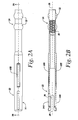
- FIGs. 2A and 2B illustrate the shaft 12 separate from the rest of the example instrument 10.
- the shaft 12 of the example instrument 10 may have a distal end 22, a proximal end 24, and a lumen 26 extending between the proximal end 24 and the distal end 22.
- the shaft 12 is generally tubular in shape having an approximately circular cross section.
- the shaft 12 may have other cross sectional shapes including elliptical or rectilinear.
- the lumen 26 of the shaft 12 is sized to receive reduction element 18, reduction element. In other embodiments, the reduction element 18, or a portion of the reduction element may be removed and other instruments, such as a screwdriver or the like, may be passed through the shaft 12.
- the shaft 12 may further include surface configurations configured to mate with the reduction element 18 to assist in the interoperation of the shaft with the reduction element 18.
- the lumen 26 of the shaft 12 may include threads 30 for directing the insertion of the reduction element 18 thru the lumen 26.
- the proximal end 24 of the shaft may also have connection elements 32 for connecting the instrument 10 to a connecter.
- the connector may be used to connect multiple instruments. The interoperation of the shaft with other elements will be discussed in more detail below.
- the engagement mechanism 14 is configured to engage a bone anchor 19, such as, for example, a hook, a monoaxial bone screw, or a polyaxial bone screw, and thereby connect the instrument 10 to the bone anchor 19 in a manner sufficient to permit manipulation of the bone anchor and the vertebra in which the bone anchor is implanted.
- the engagement mechanism 14 also serves to capture a spinal fixation element 20 such as a spinal rod that may or may not be inserted into the bone anchor 19.
- the anchor engagement mechanism 14 is one or more fingers 34Aand 34B at the distal end 22 of the shaft 12 which define a slot 36 disposed between the fingers 34A and 34B
- fingers 34A and 34B may be flexible and resilient in the radial direction to facilitate connection to a bone anchor.
- the fingers 34A and 34B may be flexed apart in the radial direction from a first, relaxed position to facilitate advancement of the fingers longitudinally over a portion of the bone anchor 19.
- the fingers 34A and 34B may provide a radially compressive force on the bone anchor as the fingers 34A and 34B attempt to return to the first, relaxed position.
- each finger 34A and 34B may include one or more radially inward facing projections 38A, 38B that are sized and shaped to seat within an opening provided in a portion of the bone anchor 19 to facilitate retention of the bone anchor 19 by the fingers 34A and 34B.
- the size, shape and number of projections can be varied depending on, for example, the opening(s) provided on the bone anchor and type of connection desired. Further examples of how the anchor engagement mechanism 14 interacts with a bone anchor 19 will be discussed below.
- the slot 36 separates fingers 34A and 34B.
- the slot 36 is configured to receive a spinal fixation element 20 that may be offset from the bone anchor 19.
- the example instrument 10 allows for the manipulation of the bone anchor 19 without requiring the spinal fixation element 20 to be inserted into the bone anchor 19.
- the slot 36 may be of significant size to allow the spinal fixation element 20 to be offset from spinal fixation element receiving member 40 of the bone anchor 19 while still allowing the fingers 34A and 34B to engage and retain the bone anchor 19.
- the slot 36 may extend approximately 20 mm from the distal end 22 of the shaft 12.
- the engagement mechanism 14 may further serve to capture or otherwise retain the spinal fixation element 20 in proximity to the bone anchor 19 while the bone anchor is manipulated.
- the fingers 34A and 34B may also be used to guide the spinal fixation element 20 into the receiving member 40 of the bone anchor 19 during reduction.
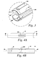
- FIGs. 4A and 4B illustrates the outer sleeve 16 separate from the rest of the example instrument 10.
- the outer sleeve 16 of the example instrument 10 is disposed about the shaft 12 and may have a distal end 42, a proximal end 44, and a lumen 46 extending between the proximal end 44 and the distal end 42.
- the outer sleeve 16 and the shaft 12 may have complementary shapes to facilitate positioning of the outer sleeve 16 over the inner shaft 12.
- the outer sleeve is generally tubular in shape.
- the longitudinal axis of the outer sleeve 16 is coincident with the longitudinal axis of the elongate shaft 12.
- the shaft 12 may be disposed within the lumen 46 of the outer sleeve 16 allowing the outer sleeve 16 to be movable relative to the shaft 12.
- the outer sleeve 16 may be movable along the longitudinal axis of the shaft 12.
- the sleeve 16 and shaft 12 may have interlocking surface configuration 50A and 50B that maintain the orientation of the sleeve 16 on the shaft 12 as the sleeve 16 is moved along the shaft 12.
- the surface configuration 50A on the sleeve 16 may be a tab and the surface configuration 50B may be a groove that receives the tab.
- the sleeve 16 may include a locking feature that allows a user to lock the sleeve 16 in position along the shaft 12.
- the sleeve 16 further includes a slot 48 corresponding to the slot 36 of the engagement mechanism 14.
- the slot 48 like the slot 36, is configured to receive a spinal fixation element 20 (See FIG. 1 ) that may be offset from the receiving member 40 of the bone anchor 19 that allows the bone anchor 19 to be engaged without requiring the spinal fixation element 20 to be inserted in the receiving member 40 of the bone anchor 19.
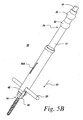
- the outer sleeve 16 is slidable along the distal end 22 of the shaft 12 to interact with the engagement mechanism 14. Examples of this can be seen in FIGs. 5A and 5B .
- the outer sleeve 16 is movable relative to the shaft 12 between a first, proximal position in which the fingers 34A and 34B of the engagement mechanism 14 are unconstrained and advanced beyond a distal end 42 of the outer sleeve 16, and a second, proximal position in which a substantial portion of the fingers 34A and 34B are disposed within and constrained by the sleeve 16.
- the fingers 34A and 34B when the sleeve 16 is in the first position, may be configured to encapsulate and capture the bone anchor 19 and spinal fixation element 20 therebetween as seen In FIG. 5A .
- fingers 34A and 34B may move apart from one another when the sleeve 16 is moved to the first position to facilitate positioning of the receiving member 40 of the bone anchor 19, between the fingers 34A and 34B.
- fingers 34A and 34B may maintain capture of the bone anchor 19 to further retain the bone anchor 19 and spinal fixation element 20 between the fingers 34A and 34B as seen in FIG. 5B .
- the fingers 34A and 34B may be constrained and inhibited from separating by the outer sleeve 16 when in the second, distal position. As such, the interaction of the sleeve 16 and the engagement mechanism 14 act as a collet to retain the bone anchor 19.
- the bone anchor 19 is retained between the fingers 34A and 34B in a manner sufficient to permit maneuvering of the spinal fixation device 20, bone anchor 19, and a vertebra in which the bone anchor 19 is implanted by manipulation of the instrument.
- the spinal fixation device 20, bone anchor 19, and vertebra may be manipulated, moved along the axis of the instrument 10, and/or moved in a direction perpendicular to the axis to the instrument 10 by the instrument 10.
- the sleeve 16 may be further moved to a third distal position as seen In FIG. 5C .
- the sleeve 16 may engage the spinal fixation element 20 received in slot 48 and serve to push the spinal fixation element 20 into the receiving member 40 of the bone anchor 19.
- the sleeve 16 may be used in the reduction, or partial reduction of the spinal fixation element 20.
- the sleeve 16 has been described as uniform piece, it should be understood that the sleeve 16 may be made of multiple parts without departing from the scope of the invention.
- the sleeve 16 may have one part used to constrain the fingers 34A and 34B and another part used to reduce the spinal fixation element 20.
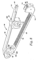
- the reduction element 18 is used to effect reduction of the spinal fixation element 20 into the receiving member 40 of the bone anchor 19.
- Figure 6A depicts a cross sectional view of the distal end of the example instrument 10 which the reduction element 18 being used for reduction of the spinal fixation element 20.
- the finger 34A and 34B of the engagement mechanism 14 have engaged and captured the bone anchor 19.
- Protrusions 38A and 38B have engaged receiving member 40 of the bone anchor 19.
- the sleeve 16 has also been moved to the second distal position constraining fingers 34A and 34B to secure the bone anchor 19.
- the reduction element 18 passes through the lumen 26 of the shaft 12 such that the distal end 60 of the reduction element 18 engages and pushes the spinal fixation element 20 into the receiving member 40 of the bone anchor 19.
- the reduction element 18 may have threads configured to engage threads 30 in the lumen 26 of the shaft 12 (See FIG. 2B ). Thus, by rotating the reduction element 18, the threads 30 serve to advance the reduction element 18 to effect reduction.
- the reduction element 18 may also be provided with a centering mechanism 62 that makes sure the reduction element 18 is centered in the lumen 26 of the shaft 12.
- the centering mechanism 62 is a housing.
- the housing 62 also includes a spring biasing mechanism 64 that engages a set of threads 66 when the distal end 60 of the instrument meets the spinal fixation element 20.
- the reduction element 18 may also be used to insert a locking element 68, such as a set screw, to secure the spinal fixation element 20 after reduction.
- a locking element 68 such as a set screw
- FIG. 6B An example of this can be seen in Figure 6B .
- the set screw 69 is place on the distal end 60 of the reduction element 18, which serves to reduce the spinal fixation element 20 as well at insert the set screw 68.
- the spring biasing mechanism 64 may provide some play between the threads 70 of the set screw 68 and the threads of the reduction element 18 in instances where the threading of the reduction element 18 and the threading of the set screw 68 are not synchronized with the threading of the receiving member 40.
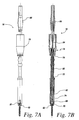
- the reduction element 18 may include multiple parts. For example, one part may be used for reduction, while another part is used for inserting the set screw 68. An example of this can be seen in FIGs. 7A and 7B .
- FIG. 7A is a side view of one embodiment of a reduction instrument 18 having two separate portions.
- FIG. 7B is a cross sectional view of the reduction element 18 in FIG. 7A .
- the reduction element 18 includes a first portion for reduction and a second portion for inserting the set screw 68.
- the first portion includes a shaft 72 having a distal end 74, a proximal end 76, and lumen extending from the proximal end 76 to the distal end 74.
- the first portion further includes a handle 78 as the proximal end 76 of the shaft 72.
- the second portion also includes a shaft 80 having a distal end 82 and a proximal end 84.
- the shaft 80 of the second portion passes through the lumen of the shaft 72 of the first portion.
- the second portion also includes a handle 86 at the proximal end 84 of the shaft 80. Because the shaft 80 of the second portion passes through the shaft 72 of the first portion, each portion of the reduction element 18 can be operated independently of the other portion.
- a user may use the handle 78 of the first portion to advance shaft 72 through the lumen 26 of the shaft 12 of the example instrument 10 to engage the spinal fixation element 20.
- the user may use handle 86 to advance the shaft 80 of the second portion to insert a set screw 68 on the distal end 82 of shaft 80 into the receiving portion 40 of the bone anchor 19.
- the ability to capture and retain a bone anchor 19 by the instrument 10 provides the ability to manipulate bone anchor 19 for adjustment. Accordingly, another example use of the instrument 10 is for de-rotation.
- the example instrument 10 may include a connection element 32 configured to engage a connector, such as the example connector 100 described below, for connecting the instrument 10 to another instrument, for example, another instrument for manipulating a vertebra.
- the shaft 14 includes a connection element 32 positioned at the proximal end 24 of the shaft 14.
- the connection element 32 may be configured to permit polyaxial motion of the instrument 10 relative to the connector.
- the connection element 32 of the example embodiment may be at least partially spherical in shape to engage a complementary shaped receiving element of the connector.
- Other possible geometries and configurations will be apparent to one skilled in the art given the benefit of this disclosure.
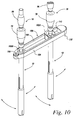
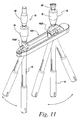
- FIGS. 8-11 illustrate one example embodiment of a connector 100 for connecting two or more instruments and facilitating cooperative movement of the instruments.
- the example connector 100 is particularly suited to connecting one or more instruments for manipulating a vertebra, such as the instrument 10 described above.
- example connector 100 is but one possible example of any number of possible configurations.
- Other possible embodiments, implementations, and configurations of connectors, receiving elements, and latch mechanisms will be apparent to one skilled in the art given the benefit of this disclosure.
- the example connector 100 may include a plurality of receiving elements 102A and 102B, each of which connects to an instrument. Any number of the receiving elements 102A and 102B may be provided.
- the connector 100 includes a first adjustable receiving element 102A for receiving a first instrument and a second receiving element 102B for receiving a second instrument.
- the first receiving element 102A and/or the second receiving element 102B may be adjustable relative to one another to facilitate connection to two spaced apart instruments.
- the first receiving element 102A is adjustable relative to the second receiving element 102B and the connector 100 and the second receiving element 102B is fixed relative to the connector 100.
- the example connector 100 may include a first arm 104 pivotably connected to second arm 106 at a pivot point defined by a hinge pin 108.
- the example connector 100 may be movable between an open position in which the first end 110 of the first arm 104 is separated from the first end 112 of the second arm 106, as illustrated in FIGS. 8 and 9 , and a closed position in which the first end 110 of the first arm 104 is coupled to the first end 112 of the second arm 106, as illustrated in FIGS. 10 and 11 .
- the open positions facilitates connection of the instruments to the receiving elements and adjustment of an adjustable receiving element, such as receiving element 102A.
- the example connector 100 may include a latch mechanism 114 for selective coupling the first end 110 of the first arm 104 to the first end 112 of the second arm 106.
- the latch mechanism 114 may include hook 120 positioned on the first arm 104 that may selectively engage a hook retaining element 122 positioned on the second arm 106.
- a cylindrically-shaped push button 126 is connected to the hook 122. Movement of the push button in a direction toward the hinge 108 causes the hook 120 to disengage from the hook retaining element 122 and, thus, releases the first arm 104 from the second arm 106.
- a spring 129 biases the push button 126 in a direction away from the hinge 108 and, thus, biases the hook 120 into an engagement position.
- the outer surface 128 of the hook 120 may be curved or angled to provide a camming surface that, when engaged by the bottom surface of the hook retaining element 122, causes the hook 120 to move from the engagement position toward the hinge 108, thus, allowing the hook 120 to engage the hook retaining element 122.
- the first arm 104 and/or second arm 106 may include a retaining member for retaining the adjustable receiving elements 102 on the arms when the connector is in the open position.
- the second arm 106 of the example connector 200 includes a retaining pin 125 for retaining the first receiving element 102A on the second arm 106.
- the retaining pin 125 may be adjusted along its axis between an extended position in which the pin 125 impedes motion of the receiving element along the arm 106 and retracted position that facilitates removal and placement of the receiving element 102 on the arm 106.
- a spring 127 may be provided to bias the pin 125 to the extended position.
- the first receiving element 102A in the example embodiment, includes a slot 132 for receiving the second arm 106 and permitting motion of the first receiving element 102A relative to the second arm 106 and other receiving elements, such as the second receiving element 102B.
- the first arm 104 includes a plurality of teeth 130 for engaging a plurality of teeth on one or more of the receiving elements, for example, the first receiving element 102A, when the connector 100 is in the closed position.
- the engagement of the teeth 130 with teeth provided on an adjustable receiving element, for example, the adjustable receiving element 102A may inhibit motion of the adjustable receiving element, thereby fixing the adjustable receiving element in position relative to the first arm 104, the second arm 106, and the other receiving elements.
- the first receiving element 102A is generally C-shaped having an opening 134 to facilitate positioning of an instrument within the receiving element 102A.
- the first arm 104 may be positioned across the opening 134 when the connector is in the closed position to retain the instrument in the first receiving element 102A.
- the first receiving element 102A may be configured to permit polyaxial motion of an instrument relative to the receiving element 102A and, thus, the connector 100.
- the first receiving element 102A may include a generally spherically shaped surface 136 that defines a seat or engagement surface for the connection element of the instrument, for example, the connection element 32 of the example instrument 10, described above.
- the instrument 10 when connected to the first receiving element 102A of the connector 100, may be moved in a plurality of directions, for example, perpendicular to, parallel to, and about the axis of the instrument 10, as illustrated in FIGs. 10 and 11 .
- the second receiving element 102B may be defined by a first arcuate surface 140A provided on the first arm 104 and a second arcuate surface 140B provided on the second arm 106.
- the first arcuate surface 140A may be spaced apart from the second arcuate surface 140B when the connector 100 is in the open position, as illustrated in FIGS. 8 and 9 , to facilitate positioning of an instrument within the second receiving element 102B.
- the connector 100 is in the closed position, as illustrated in FIGS. 10 and 11 , the first arcuate surface 140A and the second arcuate surface 140B are spaced apart a distance sufficient to retain the instrument within the second receiving element 102B.
- the second receiving element 102B may be configured to permit polyaxial motion of an instrument relative to the receiving element 102B and, thus, the connector 100.
- the first arcuate surface 140A and the second arcuate surface 140B may each have a partially spherically shaped surface 142A, 142B that cooperatively define a seat or engagement surface for the connection element of the instrument, for example, the connection element 32 of the example instrument 10, described above.
- the instrument 10, when connected to the second receiving element 102B of the connector 100 may be moved in a plurality of directions, for example, perpendicular to, parallel to, and about the axis of the instrument 10, as illustrated in FIGs. 10 and 11 .
- the connector 100 While the example embodiment of the connector 100 is described and illustrated as having two receiving elements, the number and type (i.e., fixed or adjustable) of receiving elements may be varied to accommodate the number of instruments desired to be connected.
- the connector 100 illustrated in FIGs. 13 and 14 , includes three receiving elements, a fixed receiving element and two adjustable receiving elements.
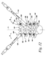
- the example instrument 10 may be employed to manipulate a bone anchor and the vertebra in which the bone anchor is implanted.
- the instrument 10 may be coupled to the receiving member or other portion of a bone anchor.
- a first instrument 10A may be coupled to the receiving member 40 of a bone anchor 19.
- a spinal construct including a plurality of bone anchors implanted in a plurality of vertebra and a spinal rod connecting the bone anchors may be positioned in advance of using the first instrument to manipulate a vertebra.
- a first bone anchor 19A may be connected to a first vertebra VB1
- a second bone anchor 19B may be connected to a second vertebra VB2
- a third bone anchor 19C may be connected to a third vertebra VB3
- a fourth bone anchor 19D may be connected to a fourth vertebra VB4.
- the first, second, third, and fourth vertebrae are adjacent one another.
- the bone anchors may be connected to non-adjacent vertebra to create the spinal construct.
- the bone anchors may be implanted into any suitable portion of the vertebrae.
- each bone anchor is implanted into a pedicle of the vertebra.
- a spinal fixation element 20A may be positioned relative to the bone anchors.
- the spinal fixation element may be positioned in or proximate to the receiving member 40 of each bone anchor 19.
- a second construct may be positioned on the contra-lateral side of the spine from the first construct.
- a fifth bone anchor 19E is connected to the first vertebra VB1 opposite the first bone anchor 19A
- a sixth bone anchor 19F is connected to the second vertebra VB2 opposite the second bone anchor 19B
- a seventh bone anchor 19G is connected to the third vertebra VB3 opposite the third bone anchor 19C
- an eighth bone anchor 19H is connected to the fourth vertebra VB4 opposite the fourth bone anchor 19D.
- a second spinal fixation element 20B may be connected to the bone anchors 19E-H.
- FIGS. are example constructs for facilitating the description of the use of the instruments described herein.
- the first instrument 10A may be manipulated to maneuver the second bone anchor 19B and the second vertebra VB2 relative to the first vertebra VB1, third vertebra VB3, and the fourth vertebra VB4.
- the first instrument 10A may be moved a direction about the axis A of the spine, as indicated by arrow R in FIG. 12 , to rotate the second vertebra VB2 about the axis A of the spine.
- the instrument 10A may be used to maneuver the second bone anchor 19B and the second vertebra VB2 in any direction.
- a second instrument 10B may be connected to the fifth bone anchor 19E, which is connected to the first vertebra VB1.
- the second instrument 10B and the first instrument 10A may be manipulated to maneuver the first vertebra VB1 and the second vertebra VB2 relative to one another.
- the first instrument 10A may be rotated about the axis A of the spine to rotate the second vertebra VB2 about the spine and the second instrument 10B may be rotated about the axis A of the spine to rotate the first vertebra VB1 about the axis A of the spine.
- the first instrument 10A and the second instrument 10B may provide counter-torque to one another to facilitate motion of the first and second vertebrae.
- the first instrument 10A and the second instrument 10B may be rotated in opposite directions about the axis A of the spine to facilitate correction of the angular orientation of the second vertebra VB2 and the first vertebra VB1.
- a reduction element 18 may be inserted through the lumen 26 of the shaft 12 of the first instrument 10A to effect reduction or insertion of a closure mechanism 68 for the second bone anchor 19B.
- FIGS. 13 and 14 illustrate an example method for manipulating a plurality of vertebrae.
- a first instrument 10A may be connected to a bone anchor 19B connected to a second vertebra.
- a second instrument 10B may be connected to a bone anchor 19E connected to a first vertebra and a third instrument 10C may be connected to a bone anchor 19H connected to a fourth vertebra VB4.
- the second and third instruments 10B, 10C may be connected by a connector, such as the connector 100 described above.
- the first receiving element 102A may be adjusted relative to the second receiving element 102B to facilitate connection of the second instrument 10B to the first receiving element 102A and the third instrument 10C to the second receiving element 102B.
- the connector 100 may be moved to manipulate the second instrument 10B and the third instrument 10C to rotate the first vertebra VB1 and the fourth vertebra VB4 relative to one another.
- the connector 100 may be rotated in a direction indicated by arrow R about the axis A to rotate the first vertebra VB1 and the fourth vertebra VB2 about the axis A of the spine and relative to the second vertebra VB2 and the third vertebra VB3.
- first instrument 10A may be rotated in cooperation with the connector 100 to rotate the second vertebra VB2 about the axis A of the spine.
- the connector 100, and the second instrument 10B and third instrument 10C connected thereto, and the first instrument 10A may provide counter torque to one another.
- the connector 100 and the first instrument 10A may be rotated in opposite directions about the axis A of the spine to facilitate correction of the angular orientation of the first vertebra VB1, the second vertebra VB2, and the fourth vertebra VB4.
- FIG. 15 illustrates an example method for rotating a single vertebra by attaching instruments to bone anchor that inserted laterally into the same vertebra.
- a first instrument 10A may be connected to a bone anchor 19A connected to a first vertebra VB1.
- a second instrument 10B may be connected to a bone anchor 19E connected to the first vertebra VB1 laterally from bone anchor 19A.
- the first and second instruments 10A and 10B may be connected by a connector, such as the connector 100 described above.
- the first receiving element 102A may be adjusted relative to the second receiving element 102B to facilitate connection of the first instrument 10A to the first receiving element 102A and the second instrument 10B to the second receiving element 102B.
- the connector 100 may be moved to manipulate the first instrument 10A and the second instrument 10B to rotate the first vertebra VB 1.
- the connector 100 may be rotated in a direction indicated by arrow R about the axis A to rotate the first vertebra VB1 about the axis A of the spine.
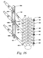
- FIG. 16 illustrates an example method for manipulating a plurality of vertebrae connected using multiple connectors.
- a first instrument 10A may be connected to a bone anchor 19E connected to a first vertebra VB 1.
- a second instrument 10B may be connected to a bone anchor 19F connected to a second vertebra VB2 and a third instrument 10C may be connected to a bone anchor 19G connected to a third vertebra VB3.
- the first and second instruments 10A, 10B may be connected by a first connector 100A.
- the first receiving element 102A of the first connector 100A may be adjusted relative to the second receiving element 102B of the first connector 100A to facilitate connection of the first instrument 10A to the first receiving element 102A and the second instrument 10B to the second receiving element 102B.
- the second and third instrument 10B, 10C may then be connected by a second connector 100B.
- the first receiving element 102A' of the second connector 100B may be adjusted relative to the second receiving element 102B' of the second connector 100B to facilitate connection of the second instrument 10B to the first receiving element 102A' and the third instrument 10C to the second receiving element 102B'.
- the connectors 100A and 100B may then be moved to manipulate the first instrument 10A, second instrument 10B, and the third instrument 10C to rotate the first vertebra VB1, second vertebra VB2 and the third vertebra VB3 relative to one another.
- the method of manipulating a bone anchor and spinal fixation element may further comprise engaging the spinal fixation element received in the slot with the reduction element, and manipulating the reduction element to reduce the spinal fixation element into the receiving member of the bone anchor.
- the method may further comprise inserting a closure mechanism into the bone anchor using the reduction element, and manipulating the reduction element to tighten the closure mechanism to restrict motion of the spinal fixation element relative to bone anchor.
- the method may further comprise: connecting a second bone anchor to a second vertebra; positioning the spinal fixation element in proximity to a receiving member of the bone anchor; connecting a second instrument to the receiving member of the second bone anchor, coupling a connector to the first instrument and to the second instrument, moving the connector to manipulate the first instrument and the second instrument to rotate the first vertebra, spinal fixation element, and the second vertebra relative to one another.
- the method may further comprise connecting a third bone anchor to a third vertebra, the third bone anchor positioned opposite the first bone anchor and the second bone anchor relative to an axis of the vertebrae, connecting a third instrument to the receiving member of the third bone anchor, and manipulating the connector and the third instrument to rotate the first vertebra and the second vertebra relative to the third vertebra.
- the third vertebra may be interposed between the first vertebra and the second vertebra.
- the at least one of the first instrument and the second instrument may be adjustable relative to the connector.
- the method may further comprise connecting a third bone anchor to a third vertebra, the third bone anchor positioned in line with the first and second bone anchors, coupling a second connector to the second instrument and to the third instrument; moving the first and second connectors to manipulate the first, second and third instrument to rotate the first vertebra, spinal fixation element, second vertebra, and third vertebra relative to one another.
- the method may further comprise: connecting a second bone anchor to the first vertebra laterally from the first bone anchor; connecting a second instrument to the receiving member of the second bone anchor, coupling a connector to the first instrument and to the second instrument, moving the connector to manipulate the first instrument and the second instrument to rotate the first vertebra.
- the method may further comprise positioning a second spinal fixation element in proximity to a receiving member of the second bone anchor prior to connecting the second instrument.
- a system for manipulating one or more vertebrae comprising:
Claims (6)
- Instrument (10) zur Handhabung eines Knochenankers (19) und eines von dem Knochenanker versetzten Wirbelsäulenfixierungselements (20), wobei das Instrument umfasst:einen Schaft (12) mit einem proximalen Ende (24), einem distalen Ende (22), einem sich zwischen dem proximalen und dem distalen Ende erstreckenden Lumen (26) und Verbindungselementen (32), wobei jedes Verbindungselement konfiguriert ist, um mit einem Verbinder (100) zum Verbinden des Instruments mit einem anderen Instrument in Eingriff zu treten,einen oder mehrere Finger (34A, B), der/die an dem distalen Ende des Schafts angeordnet ist/sind, das konfiguriert ist, um mit einem Aufnahmeelement (40) für ein Wirbelsäulenfixierungselement eines Knochenankers in Eingriff zu treten und einen Schlitz (36) zur Aufnahme eines Wirbelsäulenfixierungselements mit Vorsatz zum Aufnahmeelement für ein Wirbelsäulenfixierungselement definiert;eine äußere Hülse (16), die um den Schaft angeordnet ist, wobei die äußere Hülse einen Schlitz (48) enthält, der dem von dem einen oder dem mehreren Fingern definierten Schlitz entspricht, wobei die äußere Hülse konfiguriert ist, um über das distale Ende des Schaftes zwischen einer ersten Position, einer zweiten Position und einer dritten Position zu gleiten, wobei:• wenn sich die äußere Hülse (16) in der ersten Position befindet, der eine oder die mehreren Finger (34A, B) von der äußeren Hülse ungehindert ist/sind, wodurch der eine oder die mehreren Finger das Wirbelsäulenfixierungselement (20) in dem durch die Finger definierten Schlitz (36) aufnehmen und mit dem Aufnahmeelement (40) für ein Wirbelsäulenfixierungselement in Eingriff treten kann;• wenn sich die äußere Hülse (16) in der zweiten Position befindet, der Schlitz (48) der äußeren Hülse das Wirbelsäulenfixierungselement (20) aufnimmt, das von dem Aufnahmeelement (40) für ein Wirbelsäulenfixierungselement versetzt ist, und der Finger oder die mehreren Finger (34A,B) von der äußeren Hülse gehindert werden, wodurch das Wirbelsäulenfixierungselement in dem von den Fingern definierten Schlitz (36) und der Eingriff des Aufnahmeelements für ein Wirbelsäulenfixierungselement des Knochenankers durch den einen oder die mehreren Finger gesichert wird, um eine Handhabung des Wirbelsäulenfixierungselements und des Knochenankers durch das Instrument zuzulassen;• und wobei, wenn die äußere Hülse (16) über das distale Ende (22) des inneren Schaftes (12) zur dritten Position geschoben wird, dies bewirkt, dass die äußere Hülse das versetzte Wirbelsäulenfixierungselement (20) in das Aufnahmeelement (40) für ein Wirbelsäulenfixierungselement des Knochenankers (19) reduziert; und• ein Reduktionselement (18), das konfiguriert ist, um durch das Lumen (26) des Schaftes (12) zu treten, so dass es mit dem versetzten Wirbelsäulenfixierungselement (20) in Eingriff treten kann, um das versetzte Wirbelsäulenfixierungselement in das Aufnahmeelement (40) für ein Wirbelsäulenfixierungselement des Knochenankers (19) zu reduzieren, wobei das Reduktionselement ferner konfiguriert ist, um einen Verriegelungsmechanismus (68) in den Knochenanker einzusetzen, um das Wirbelsäulenfixierungselement an dem Knochenanker zu sichern.
- Instrument nach Anspruch 1, wobei die Verbindungselemente (32) konfiguriert sind, um eine polyaxiale Bewegung des Instruments (10) relativ zum Verbinder (100) zu ermöglichen.
- Instrument nach Anspruch 1, wobei das Lumen (26) des Schaftes (12) Innengewinde (30) für einen Eingriff mit korrespondierenden Gewinden an dem Reduktionselement (18), das durch das Lumen des Schaftes tritt, enthält.
- System zur Handhabung von einem oder mehreren Wirbeln, wobei das System umfasst:ein erstes Instrument (10), wobei das erste Instrument ein Instrument zur Handhabung eines Knochenankers und eines Wirbelsäulenfixierungselements nach Anspruch 1 ist;ein zweites Instrument (10), wobei das zweite Instrument ein Instrument zur Handhabung eines Knochenankers und eines Wirbelsäulenfixierungselements nach Anspruch 1 ist;einen Verbinder (10), der das erste Instrument und das zweite Instrument verbindet, wobei der Verbinder ein erstes Aufnahmeelement (102A) zur Aufnahme des ersten Instruments und ein zweites Aufnahmeelement (102B) zur Aufnahme des zweiten Instruments enthält, wobei das erste Aufnahmeelement relativ zum zweiten Aufnahmeelement einstellbar ist.
- System nach Anspruch 4, wobei das erste Instrument relativ zum ersten Aufnahmeelement winkelverstellbar ist.
- System nach Anspruch 5, wobei das zweite Instrument relativ zum zweiten Aufnahmeelement winkelverstellbar ist.
Applications Claiming Priority (2)
| Application Number | Priority Date | Filing Date | Title |
|---|---|---|---|
| US12/075,412 US8608746B2 (en) | 2008-03-10 | 2008-03-10 | Derotation instrument with reduction functionality |
| PCT/US2009/036343 WO2009114422A2 (en) | 2008-03-10 | 2009-03-06 | Derotation instrument with reduction functionality |
Publications (3)
| Publication Number | Publication Date |
|---|---|
| EP2249723A2 EP2249723A2 (de) | 2010-11-17 |
| EP2249723A4 EP2249723A4 (de) | 2013-04-03 |
| EP2249723B1 true EP2249723B1 (de) | 2014-06-04 |
Family
ID=41054454
Family Applications (1)
| Application Number | Title | Priority Date | Filing Date |
|---|---|---|---|
| EP09719006.0A Active EP2249723B1 (de) | 2008-03-10 | 2009-03-06 | Derotationsinstrument mit reduktionsfunktion |
Country Status (7)
| Country | Link |
|---|---|
| US (2) | US8608746B2 (de) |
| EP (1) | EP2249723B1 (de) |
| JP (1) | JP5558370B2 (de) |
| CN (1) | CN102026584B (de) |
| AU (1) | AU2009223550B2 (de) |
| CA (1) | CA2717758C (de) |
| WO (1) | WO2009114422A2 (de) |
Cited By (2)
| Publication number | Priority date | Publication date | Assignee | Title |
|---|---|---|---|---|
| DE102016224503B3 (de) | 2016-12-08 | 2018-05-24 | Premiere Medical Gmbh | Chirurgisches Repositionsinstrument |
| DE102016224493A1 (de) * | 2016-12-08 | 2018-06-14 | Premiere Medical Gmbh | Chirurgisches Repositionsinstrument |
Families Citing this family (104)
| Publication number | Priority date | Publication date | Assignee | Title |
|---|---|---|---|---|
| US7887539B2 (en) | 2003-01-24 | 2011-02-15 | Depuy Spine, Inc. | Spinal rod approximators |
| US20190307493A1 (en) * | 2004-02-27 | 2019-10-10 | Nuvasive | Orthopedic implant rod reduction tool set and method |
| US8226690B2 (en) | 2005-07-22 | 2012-07-24 | The Board Of Trustees Of The Leland Stanford Junior University | Systems and methods for stabilization of bone structures |
| US8267969B2 (en) | 2004-10-20 | 2012-09-18 | Exactech, Inc. | Screw systems and methods for use in stabilization of bone structures |
| US7951172B2 (en) | 2005-03-04 | 2011-05-31 | Depuy Spine Sarl | Constrained motion bone screw assembly |
| US7951175B2 (en) | 2005-03-04 | 2011-05-31 | Depuy Spine, Inc. | Instruments and methods for manipulating a vertebra |
| US7608081B2 (en) * | 2005-05-23 | 2009-10-27 | Custom Spine, Inc. | Rod reducer |
| US8523865B2 (en) | 2005-07-22 | 2013-09-03 | Exactech, Inc. | Tissue splitter |
| US8096996B2 (en) | 2007-03-20 | 2012-01-17 | Exactech, Inc. | Rod reducer |
| JP5190111B2 (ja) | 2007-05-18 | 2013-04-24 | ストライカー・スピン | 直接的に椎骨を回旋させるための装置および方法 |
| US8007522B2 (en) | 2008-02-04 | 2011-08-30 | Depuy Spine, Inc. | Methods for correction of spinal deformities |
| US8439922B1 (en) | 2008-02-06 | 2013-05-14 | NiVasive, Inc. | Systems and methods for holding and implanting bone anchors |
| US8608746B2 (en) | 2008-03-10 | 2013-12-17 | DePuy Synthes Products, LLC | Derotation instrument with reduction functionality |
| US8709015B2 (en) * | 2008-03-10 | 2014-04-29 | DePuy Synthes Products, LLC | Bilateral vertebral body derotation system |
| US10973556B2 (en) | 2008-06-17 | 2021-04-13 | DePuy Synthes Products, Inc. | Adjustable implant assembly |
| US8105362B2 (en) * | 2008-06-30 | 2012-01-31 | Duarte Luis E | Percutaneous spinal rod insertion system and related methods |
| FR2937855B1 (fr) * | 2008-11-05 | 2010-12-24 | Warsaw Orthopedic Inc | Instrument d'introduction progressive d'une tige vertebrale. |
| US9161788B2 (en) * | 2008-12-17 | 2015-10-20 | DePuy Synthes Products, Inc. | Rod reducer apparatus for spinal corrective surgery |
| CN102497828B (zh) | 2009-05-20 | 2015-09-09 | 斯恩蒂斯有限公司 | 患者安装的牵开件 |
| CN101912300B (zh) * | 2009-09-29 | 2012-08-22 | 张强 | 微创胸腰椎骨折椎弓根钉固定多节段置钉器械 |
| US8986349B1 (en) | 2009-11-11 | 2015-03-24 | Nuvasive, Inc. | Systems and methods for correcting spinal deformities |
| US8475467B2 (en) | 2009-12-07 | 2013-07-02 | Globus Medical, Inc. | Derotation apparatus for treating spinal irregularities |
| FR2954689B1 (fr) * | 2009-12-28 | 2012-12-21 | Sterispine | Dispositif et methode pour la chirurgie rachidienne. |
| US8545505B2 (en) | 2010-01-15 | 2013-10-01 | Pioneer Surgical Technology, Inc. | Low friction rod persuader |
| US8540719B2 (en) * | 2010-02-09 | 2013-09-24 | Aesculap Implant Systems, Llc | Percutaneous rod insertion system and method |
| US9393048B2 (en) | 2010-02-23 | 2016-07-19 | K2M, Inc. | Polyaxial bonescrew assembly |
| DE102010016448A1 (de) | 2010-04-14 | 2011-10-20 | Aesculap Ag | Orthopädisches Fixationssystem und Zielvorrichtung für ein derartiges Fixationssystem |
| US8535318B2 (en) | 2010-04-23 | 2013-09-17 | DePuy Synthes Products, LLC | Minimally invasive instrument set, devices and related methods |
| US8206395B2 (en) * | 2010-06-18 | 2012-06-26 | Spine Wave, Inc. | Surgical instrument and method for the distraction or compression of bones |
| US9393049B2 (en) | 2010-08-20 | 2016-07-19 | K2M, Inc. | Spinal fixation system |
| AU2013201293B2 (en) * | 2010-08-20 | 2014-12-18 | K2M, Inc. | Spinal Fixation System |
| AU2011291476B2 (en) | 2010-08-20 | 2014-02-13 | K2M, Inc. | Spinal fixation system |
| CN103006312B (zh) * | 2010-09-03 | 2017-11-03 | 张强 | 微创骨折螺钉置入开口器 |
| US9101412B2 (en) | 2010-09-09 | 2015-08-11 | DePuy Synthes Products, Inc. | Vertebral adjustment systems for spine alignment |
| US8623022B2 (en) | 2010-09-20 | 2014-01-07 | Zimmer Spine, Inc. | Surgical instrument support system and method |
| US9198698B1 (en) * | 2011-02-10 | 2015-12-01 | Nuvasive, Inc. | Minimally invasive spinal fixation system and related methods |
| EP3692937A1 (de) * | 2011-04-15 | 2020-08-12 | Synthes GmbH | Fixieranordnung für einem zwischenwirbelimplantat |
| US9907582B1 (en) | 2011-04-25 | 2018-03-06 | Nuvasive, Inc. | Minimally invasive spinal fixation system and related methods |
| US8556904B2 (en) | 2011-05-05 | 2013-10-15 | Warsaw Orthopedic, Inc. | Anchors extender assemblies and methods for using |
| US20120323242A1 (en) * | 2011-06-16 | 2012-12-20 | Industrial Technology Research Institute | Surgical awl and method of using the same |
| FR2976784B1 (fr) * | 2011-06-23 | 2013-07-05 | Spineway | Dispositif chirurgical pour la correction de la deformation de la colonne vertebrale |
| EP2736428B1 (de) | 2011-07-29 | 2017-06-07 | Aesculap AG | Chirurgisches instrument für die wirbelsäulenchirurgie |
| DE102011053295A1 (de) * | 2011-09-06 | 2013-03-07 | Aesculap Ag | Polyaxiale Pedikelschraube mit provisorischer Fixierung |
| US9750548B2 (en) * | 2011-10-11 | 2017-09-05 | Globus Medical, Inc. | Rod-reducing apparatus and associated methods |
| US9333012B2 (en) * | 2011-10-25 | 2016-05-10 | Warsaw Orthopedic, Inc. | Spinal implant system and method |
| US9125703B2 (en) * | 2012-01-16 | 2015-09-08 | K2M, Inc. | Rod reducer, compressor, distractor system |
| US9220539B2 (en) * | 2012-03-19 | 2015-12-29 | Warsaw Orthopedic, Inc. | Spinal implant system and method |
| JP6189939B2 (ja) | 2012-05-11 | 2017-08-30 | オーソペディアトリクス・コーポレーション | 外科用連結器および器具類 |
| US9179957B2 (en) * | 2012-08-09 | 2015-11-10 | Spinecraft, LLC | Systems, assemblies and methods for spinal derotation |
| US9572598B2 (en) * | 2012-08-09 | 2017-02-21 | Spine Craft, LLC | Uniplanar surgical screw assembly |
| US9782204B2 (en) | 2012-09-28 | 2017-10-10 | Medos International Sarl | Bone anchor assemblies |
| ES2545756T3 (es) * | 2012-11-07 | 2015-09-15 | Stryker Trauma Sa | Instrumento de compresión |
| US9918752B2 (en) * | 2012-11-29 | 2018-03-20 | Warsaw Orthopedic, Inc. | Spinal implant system and method |
| US20140336709A1 (en) * | 2013-03-13 | 2014-11-13 | Baxano Surgical, Inc. | Multi-threaded pedicle screw system |
| US9510875B2 (en) | 2013-03-14 | 2016-12-06 | Stryker European Holdings I, Llc | Systems and methods for percutaneous spinal fusion |
| US9724145B2 (en) | 2013-03-14 | 2017-08-08 | Medos International Sarl | Bone anchor assemblies with multiple component bottom loading bone anchors |
| US20140277153A1 (en) | 2013-03-14 | 2014-09-18 | DePuy Synthes Products, LLC | Bone Anchor Assemblies and Methods With Improved Locking |
| US9259247B2 (en) | 2013-03-14 | 2016-02-16 | Medos International Sarl | Locking compression members for use with bone anchor assemblies and methods |
| US9775660B2 (en) | 2013-03-14 | 2017-10-03 | DePuy Synthes Products, Inc. | Bottom-loading bone anchor assemblies and methods |
| US10342582B2 (en) | 2013-03-14 | 2019-07-09 | DePuy Synthes Products, Inc. | Bone anchor assemblies and methods with improved locking |
| US9486256B1 (en) | 2013-03-15 | 2016-11-08 | Nuvasive, Inc. | Rod reduction assemblies and related methods |
| US9668789B2 (en) | 2013-03-15 | 2017-06-06 | Ebi, Llc | Reduction instrument, surgical assembly including a reduction instrument and related method |
| US10136927B1 (en) | 2013-03-15 | 2018-11-27 | Nuvasive, Inc. | Rod reduction assemblies and related methods |
| US9173687B2 (en) * | 2013-03-15 | 2015-11-03 | DePuy Synthes Products, Inc. | Fulcrum cap for spinal constructs |
| US10058355B2 (en) * | 2013-05-13 | 2018-08-28 | Neo Medical S.A. | Orthopedic implant kit |
| DE102013108036A1 (de) | 2013-07-26 | 2015-01-29 | Kilian Kraus | Instrumentensatz für die perkutane Wirbelsäulenstabilisierung mit Hilfe von Pedikelschrauben und Stäben |
| US9265533B2 (en) * | 2013-09-04 | 2016-02-23 | Aesculap Implant Systems, Llc | Rod persuader, system and method |
| DE102013111683A1 (de) | 2013-10-23 | 2015-04-23 | Aesculap Ag | Wirbelsäulenstabilisierungsystem, medizinisches Instrumentarium und medizinische Vorrichtung zum parallelen Ausrichten medizinischer Instrumente |
| JP6623168B2 (ja) * | 2014-03-26 | 2019-12-18 | メダクタ・インターナショナル・ソシエテ・アノニム | 外科用ねじ杆をインプラントする装置 |
| US9526553B2 (en) * | 2014-04-04 | 2016-12-27 | K2M, Inc. | Screw insertion instrument |
| US10405897B2 (en) * | 2014-04-08 | 2019-09-10 | Medacta International Sa | Fixing device for a surgical anchor member |
| US10531904B2 (en) | 2014-04-30 | 2020-01-14 | Eric D. Kolb | Bone screw with apertures |
| EP2957246B1 (de) * | 2014-06-17 | 2017-04-19 | Biedermann Technologies GmbH & Co. KG | Verlängerungsvorrichtung eines Knochenankers, insbesondere für die minimalinvasive Chirurgie |
| US9943344B2 (en) * | 2015-01-15 | 2018-04-17 | K2M, Inc. | Rod reducer |
| US11672575B2 (en) | 2015-03-11 | 2023-06-13 | Warsaw Orthopedic, Inc. | Surgical instrument and method |
| US11278325B2 (en) | 2015-03-11 | 2022-03-22 | Warsaw Orthopedic, Inc. | Surgical instrument and method |
| US9681899B2 (en) | 2015-03-23 | 2017-06-20 | Globus Medical, Inc. | Orthopedic derotation devices and methods of installation thereof |
| US11602379B2 (en) | 2015-03-23 | 2023-03-14 | Globus Medical, Inc. | Orthopedic derotation devices and methods of installation thereof |
| TWI547259B (zh) * | 2015-04-28 | 2016-09-01 | 鐿鈦科技股份有限公司 | 脊椎融合手術之植入器械及其椎間融合器 |
| CN104905872B (zh) * | 2015-05-12 | 2017-05-31 | 山东威高骨科材料股份有限公司 | 一种蛙式钳钳头 |
| US9974577B1 (en) | 2015-05-21 | 2018-05-22 | Nuvasive, Inc. | Methods and instruments for performing leveraged reduction during single position spine surgery |
| EP3106110B1 (de) * | 2015-06-16 | 2017-10-11 | Biedermann Technologies GmbH & Co. KG | Verlängerungsvorrichtung für einen knochenanker |
| US10278687B2 (en) * | 2015-08-18 | 2019-05-07 | Globus Medical, Inc. | Devices and systems for surgical retraction |
| US10022157B2 (en) | 2015-11-20 | 2018-07-17 | Blackstone Medical, Inc. | Convertible screw for spinal fixation |
| US10194960B1 (en) | 2015-12-03 | 2019-02-05 | Nuvasive, Inc. | Spinal compression instrument and related methods |
| US10524843B2 (en) * | 2016-05-06 | 2020-01-07 | K2M, Inc. | Rotation shaft for a rod reducer |
| US10398481B2 (en) | 2016-10-03 | 2019-09-03 | Nuvasive, Inc. | Spinal fixation system |
| US10820936B2 (en) | 2016-11-04 | 2020-11-03 | Orthopedic Renovation Technologies, Llc | Pedicle screw removal tool and method of use |
| US11534223B2 (en) | 2016-11-04 | 2022-12-27 | Orthopedic Renovation Technologies, Llc | Pedicle screw removal tool and method of use |
| US10779866B2 (en) | 2016-12-29 | 2020-09-22 | K2M, Inc. | Rod reducer assembly |
| US10485590B2 (en) | 2017-01-18 | 2019-11-26 | K2M, Inc. | Rod reducing device |
| EP3675754A1 (de) * | 2017-08-30 | 2020-07-08 | Zimmer Biomet Spine, Inc. | System zur dynamischen stabilisierung |
| EP3517062B1 (de) * | 2018-01-26 | 2021-03-17 | Aesculap AG | Wirbelsäulenneupositionierungsinstrument und wirbelsäulenneupositionierungssystem |
| US10918424B2 (en) | 2018-03-12 | 2021-02-16 | Zimmer Biomet Spine, Inc. | Rod reducer ratchet lock-out mechanism |
| US11051861B2 (en) | 2018-06-13 | 2021-07-06 | Nuvasive, Inc. | Rod reduction assemblies and related methods |
| US10959859B2 (en) * | 2018-07-25 | 2021-03-30 | Warsaw Orthopedic, Inc. | Spinal implant system and method |
| US10980577B2 (en) * | 2019-04-01 | 2021-04-20 | Aesculap Implant Systems, Llc | Spinal deformity derotation instrument |
| US11229462B2 (en) | 2019-05-07 | 2022-01-25 | Warsaw Orthopedic, Inc. | Head assembly inserters |
| US11553947B2 (en) | 2019-07-16 | 2023-01-17 | Aesculap Implant Systems, Llc | Spinal deformity sequential persuader |
| US11134994B2 (en) * | 2020-01-30 | 2021-10-05 | Warsaw Orthopedic, Inc. | Spinal-correction system having threaded extender tabs and reduction tab extenders |
| US11617603B2 (en) | 2020-12-09 | 2023-04-04 | Warsaw Orthopedic, Inc. | Modular surgical instrument system with ratcheting reduction mechanism |
| US11432851B2 (en) * | 2021-02-04 | 2022-09-06 | Warsaw Orthopedic, Inc. | Surgical instrument and method |
| US11432852B1 (en) | 2021-03-22 | 2022-09-06 | Warsaw Orthopedic, Inc. | Screw shank based tissue retraction |
| US11406431B1 (en) | 2021-05-10 | 2022-08-09 | Warsaw Orthopedic, Inc. | Systems and methods of use and modular instruments with a lateral reducer |
Family Cites Families (348)
| Publication number | Priority date | Publication date | Assignee | Title |
|---|---|---|---|---|
| US410780A (en) | 1889-09-10 | Maurice cah | ||
| US445513A (en) | 1891-01-27 | powell | ||
| US1116532A (en) | 1912-03-14 | 1914-11-10 | Ralph A Armstrong | Screw-driver attachment. |
| US1470313A (en) | 1922-09-19 | 1923-10-09 | L M Tryer | Piston-ring squeezer |
| US1628144A (en) | 1924-05-16 | 1927-05-10 | Herrmann William | Screw driver |
| US1709766A (en) | 1926-09-16 | 1929-04-16 | Shawmut Eng Co | Yarn carrier |
| US1889330A (en) | 1932-02-23 | 1932-11-29 | Homer C Humes | Screw holding attachment for screw drivers |
| US1925385A (en) | 1932-11-08 | 1933-09-05 | Homer C Humes | Screw driver with screw holders |
| US2113246A (en) | 1937-05-17 | 1938-04-05 | Wappler Frederick Charles | Endoscopic forceps |
| US2248057A (en) | 1939-01-25 | 1941-07-08 | Bell Telephone Labor Inc | Electrical cutting device |
| US2248054A (en) | 1939-06-07 | 1941-07-08 | Becker Joseph | Screw driver |
| US2291413A (en) | 1941-06-13 | 1942-07-28 | John R Siebrandt | Bone clamping and wire adjusting means |
| US2370407A (en) | 1944-01-05 | 1945-02-27 | Zimmer Mfg Company | Screw driver |
| US2669896A (en) * | 1951-01-19 | 1954-02-23 | Robert S Clough | Retractable jaw wrench having parallel resilient jaws |
| US2800820A (en) | 1954-06-04 | 1957-07-30 | Groov Pin Corp | Driver tool for self tapping inserts, struds, screw bolts, and the like |
| US2952285A (en) * | 1958-12-09 | 1960-09-13 | Gramiger A G Geb | Screwdrivers |
| US3604487A (en) * | 1969-03-10 | 1971-09-14 | Richard S Gilbert | Orthopedic screw driving means |
| US3960147A (en) | 1975-03-10 | 1976-06-01 | Murray William M | Compression bone staples and methods of compressing bone segments |
| PL105977B1 (pl) | 1976-06-28 | 1979-11-30 | Wyzsza Szkola Inzynierska | Przyrzad do korekcji skrzywien kregoslupa |
| US4237875A (en) | 1979-02-23 | 1980-12-09 | Towmotor Corporation | Dynamic intramedullary compression nailing |
| US4411259A (en) | 1980-02-04 | 1983-10-25 | Drummond Denis S | Apparatus for engaging a hook assembly to a spinal column |
| JPS56147085U (de) * | 1980-04-04 | 1981-11-05 | ||
| DE3121271A1 (de) | 1981-05-29 | 1982-12-23 | Max Bernhard 7900 Ulm Ulrich | Distraktionsgeraet zur korrektur insbesondere kyphotischer wirbelsaeulenbereiche |
| US4809695A (en) | 1981-10-21 | 1989-03-07 | Owen M. Gwathmey | Suturing assembly and method |
| DE3414374C2 (de) * | 1984-04-16 | 1986-12-18 | Patrick Dr. 3590 Bad Wildungen Kluger | Vorrichtung zum Einrichten einer Wirbelsäule mit geschädigten Wirbelkörpern |
| US4743260A (en) * | 1985-06-10 | 1988-05-10 | Burton Charles V | Method for a flexible stabilization system for a vertebral column |
| US4655223A (en) | 1985-08-05 | 1987-04-07 | Kim Daniel S Y | Frenotomy method and apparatus |
| US5181971A (en) * | 1986-05-20 | 1993-01-26 | Canon Kabushiki Kaisha | Magnet and method of manufacturing the same |
| DE3711091A1 (de) * | 1987-04-02 | 1988-10-13 | Kluger Patrick | Vorrichtung zum einrichten einer wirbelsaeule mit geschaedigten wirbelkoerpern |
| US4896661A (en) | 1988-02-05 | 1990-01-30 | Pfizer, Inc. | Multi purpose orthopedic ratcheting forceps |
| US5468241A (en) * | 1988-02-18 | 1995-11-21 | Howmedica Gmbh | Support device for the human vertebral column |
| DE8802112U1 (de) | 1988-02-18 | 1989-07-13 | Howmedica Gmbh, 2314 Schoenkirchen, De | |
| US4887596A (en) * | 1988-03-02 | 1989-12-19 | Synthes (U.S.A.) | Open backed pedicle screw |
| US4950269A (en) | 1988-06-13 | 1990-08-21 | Acromed Corporation | Spinal column fixation device |
| FR2633177B1 (fr) * | 1988-06-24 | 1991-03-08 | Fabrication Materiel Orthopedi | Implant pour dispositif d'osteosynthese rachidienne, notamment en traumatologie |
| WO1990002527A1 (en) | 1988-09-09 | 1990-03-22 | Australian Defence Industries Pty. Limited | Spinal distractor |
| FR2642645B1 (fr) | 1989-02-03 | 1992-08-14 | Breard Francis | Stabilisateur intervertebral souple ainsi que procede et appareillage pour le controle de sa tension avant mise en place sur le rachis |
| USRE36221E (en) * | 1989-02-03 | 1999-06-01 | Breard; Francis Henri | Flexible inter-vertebral stabilizer as well as process and apparatus for determining or verifying its tension before installation on the spinal column |
| US4987892A (en) * | 1989-04-04 | 1991-01-29 | Krag Martin H | Spinal fixation device |
| FR2645732B1 (fr) * | 1989-04-13 | 1997-01-03 | Cotrel Yves | Implant vertebral pour dispositif d'osteosynthese |
| DE3923996A1 (de) | 1989-07-20 | 1991-01-31 | Lutz Biedermann | Aufnahmeteil zum gelenkigen verbinden mit einer schraube zum bilden einer pedikelschraube |
| JP3158405B2 (ja) * | 1989-07-21 | 2001-04-23 | ブラザー工業株式会社 | フアクシミリ装置の通信管理情報処理装置 |
| US5261913A (en) | 1989-07-26 | 1993-11-16 | J.B.S. Limited Company | Device for straightening, securing, compressing and elongating the spinal column |
| US5014407A (en) | 1989-09-28 | 1991-05-14 | Boughten Larry R | Tube expanding device |
| CA2035348C (fr) * | 1990-02-08 | 2000-05-16 | Jean-Louis Vignaud | Dispositif de fixation orientable de tiges d'osteosynthese rachidienne |
| WO1991016020A1 (en) * | 1990-04-26 | 1991-10-31 | Danninger Medical Technology, Inc. | Transpedicular screw system and method of use |
| US5102412A (en) * | 1990-06-19 | 1992-04-07 | Chaim Rogozinski | System for instrumentation of the spine in the treatment of spinal deformities |
| US5417533A (en) * | 1990-07-13 | 1995-05-23 | National Medical Specialty, Inc. | Bone screw with improved threads |
| US5120171A (en) * | 1990-11-27 | 1992-06-09 | Stuart Surgical | Bone screw with improved threads |
| CH685850A5 (de) * | 1990-11-26 | 1995-10-31 | Synthes Ag | Verankerungseinrichtung |
| US5020519A (en) | 1990-12-07 | 1991-06-04 | Zimmer, Inc. | Sagittal approximator |
| FR2672202B1 (fr) * | 1991-02-05 | 1993-07-30 | Safir | Implant chirurgical osseux, notamment pour stabilisateur inter-vertebral. |
| US5219349A (en) * | 1991-02-15 | 1993-06-15 | Howmedica, Inc. | Spinal fixator reduction frame |
| US5391170A (en) | 1991-12-13 | 1995-02-21 | David A. McGuire | Angled surgical screw driver and methods of arthroscopic ligament reconstruction |
| DE4107480C2 (de) | 1991-03-08 | 1994-09-22 | Heinrich Ulrich | Pedikelschraube für Implantate zur Korrektur und Stabilisierung der Wirbelsäule |
| US5176678A (en) * | 1991-03-14 | 1993-01-05 | Tsou Paul M | Orthopaedic device with angularly adjustable anchor attachments to the vertebrae |
| FR2676911B1 (fr) * | 1991-05-30 | 1998-03-06 | Psi Ste Civile Particuliere | Dispositif de stabilisation intervertebrale a amortisseurs. |
| FR2677242A1 (fr) | 1991-06-05 | 1992-12-11 | Jeanson Jean Francois | Dispositif pousse-barre d'etaiement rachidien. |
| FR2680314B1 (fr) | 1991-08-16 | 1993-11-19 | Guy Lebosse | Ciseaux de cóoeliochirurgie droit ou courbe de champs electrocoagulants en mode bi polaire. |
| US5330474A (en) * | 1991-09-23 | 1994-07-19 | Lin Chih I | Vertebral locking and retrieving system |
| DE4202748A1 (de) | 1992-01-31 | 1993-08-05 | Kluger Patrick | Wirbelsaeulenimplantat und -repositionsinstrumente |
| DE9202587U1 (de) | 1992-02-28 | 1992-04-16 | Howmedica Gmbh, 2314 Schoenkirchen, De | |
| DE9202745U1 (de) * | 1992-03-02 | 1992-04-30 | Howmedica Gmbh, 2314 Schoenkirchen, De | |
| US5306248A (en) | 1992-04-07 | 1994-04-26 | C. R. Bard, Inc. | Selectively controllable inflation-deflation device adapted for use in angioplasty procedures |
| EP0572790B1 (de) | 1992-06-04 | 1996-02-14 | Synthes AG, Chur | Osteosynthetisches Befestigungselement |
| JP3308271B2 (ja) * | 1992-06-25 | 2002-07-29 | ジンテーズ アクチエンゲゼルシャフト,クール | 骨接合用固定装置 |
| USD346217S (en) * | 1992-07-13 | 1994-04-19 | Acromed Corporation | Combined hook holder and rod mover for spinal surgery |
| US5545165A (en) | 1992-10-09 | 1996-08-13 | Biedermann Motech Gmbh | Anchoring member |
| US5281223A (en) * | 1992-09-21 | 1994-01-25 | Ray R Charles | Tool and method for derotating scoliotic spine |
| US5334203A (en) | 1992-09-30 | 1994-08-02 | Amei Technologies Inc. | Spinal fixation system and methods |
| FR2696335B1 (fr) | 1992-10-07 | 1994-12-02 | Bouvet Jean Claude | Dispositif d'immobilisation d'une barre pour, notamment, ostéosynthèse ou arthrodèse. |
| US5263939A (en) * | 1992-10-09 | 1993-11-23 | Surgin Surgical Instrumentation, Inc. | Retainer for laparoscopic cannula |
| US5484440A (en) | 1992-11-03 | 1996-01-16 | Zimmer, Inc. | Bone screw and screwdriver |
| DE4238339C2 (de) | 1992-11-13 | 1994-10-06 | Peter Brehm | Pedikelschraube und Haltehaken zum Festlegen einer Versteifungsstange und Instrumentarium zum Justieren und Befestigen der Versteifungsstange an der Pedikelschraube oder dem Haltehaken |
| US5814046A (en) | 1992-11-13 | 1998-09-29 | Sofamor S.N.C. | Pedicular screw and posterior spinal instrumentation |
| DE4243951C2 (de) * | 1992-12-23 | 1997-07-03 | Plus Endoprothetik Ag | Vorrichtung zur Versteifung eines aus wenigstens zwei Wirbeln bestehenden Wirbelsäulenabschnitts |
| US5282801A (en) * | 1993-02-17 | 1994-02-01 | Danek Medical, Inc. | Top tightening clamp assembly for a spinal fixation system |
| US5415661A (en) * | 1993-03-24 | 1995-05-16 | University Of Miami | Implantable spinal assist device |
| IL105183A (en) | 1993-03-28 | 1996-07-23 | Yehiel Gotfried | Surgical device for connection of fractured bones |
| US5487744A (en) * | 1993-04-08 | 1996-01-30 | Advanced Spine Fixation Systems, Inc. | Closed connector for spinal fixation systems |
| US5364397A (en) | 1993-06-01 | 1994-11-15 | Zimmer, Inc. | Spinal coupler seater with dual jaws and an independent plunger |
| FR2722393B1 (fr) | 1993-08-27 | 1996-08-23 | Martin Jean Raymond | Materiel ancillaire de correction d'une deformation vertebrale |
| FR2709246B1 (fr) | 1993-08-27 | 1995-09-29 | Martin Jean Raymond | Orthèse vertébrale implantée dynamique. |
| US5431658A (en) | 1994-02-14 | 1995-07-11 | Moskovich; Ronald | Facilitator for vertebrae grafts and prostheses |
| US5499983A (en) * | 1994-02-23 | 1996-03-19 | Smith & Nephew Richards, Inc. | Variable angle spinal screw |
| ES2133517T3 (es) | 1994-02-28 | 1999-09-16 | Sulzer Orthopadie Ag | Estabilizador para vertebras adyacentes. |
| US5522816A (en) | 1994-03-09 | 1996-06-04 | Acromed Corporation | Transverse connection for spinal column corrective devices |
| US5551320A (en) | 1994-05-13 | 1996-09-03 | Horobec; Bill R. | System for the removing of threaded fasteners |
| US5536127A (en) * | 1994-10-13 | 1996-07-16 | Pennig; Dietmar | Headed screw construction for use in fixing the position of an intramedullary nail |
| US6176861B1 (en) * | 1994-10-25 | 2001-01-23 | Sdgi Holdings, Inc. | Modular spinal system |
| FR2729291B1 (fr) | 1995-01-12 | 1997-09-19 | Euros Sa | Implant rachidien |
| US5616143A (en) | 1995-02-06 | 1997-04-01 | Schlapfer; Johannes F. | Surgical forceps |
| US5591235A (en) | 1995-03-15 | 1997-01-07 | Kuslich; Stephen D. | Spinal fixation device |
| DE19509332C1 (de) * | 1995-03-15 | 1996-08-14 | Harms Juergen | Verankerungselement |
| US5591166A (en) * | 1995-03-27 | 1997-01-07 | Smith & Nephew Richards, Inc. | Multi angle bone bolt |
| US5882350A (en) * | 1995-04-13 | 1999-03-16 | Fastenetix, Llc | Polyaxial pedicle screw having a threaded and tapered compression locking mechanism |
| US5667513A (en) * | 1995-06-07 | 1997-09-16 | Smith & Nephew Dyonics Inc. | Soft tissue anchor delivery apparatus |
| US5549608A (en) * | 1995-07-13 | 1996-08-27 | Fastenetix, L.L.C. | Advanced polyaxial locking screw and coupling element device for use with rod fixation apparatus |
| FR2737222B1 (fr) | 1995-07-24 | 1997-10-17 | Transgene Sa | Nouveaux vecteurs viraux et lignee pour la therapie genique |
| US5643263A (en) * | 1995-08-14 | 1997-07-01 | Simonson; Peter Melott | Spinal implant connection assembly |
| US5683399A (en) | 1995-12-01 | 1997-11-04 | Stelkast Incorporated | Acetabular cup insertion tool |
| FR2742040B1 (fr) | 1995-12-07 | 1998-01-23 | Groupe Lepine | Dispositif d'assemblage pour pieces allongees de materiel d'osteosynthese, notamment rachidienne |
| US5697933A (en) | 1995-12-18 | 1997-12-16 | Medicinelodge, Inc. | Bone-tendon-bone drill guide |
| US5649931A (en) * | 1996-01-16 | 1997-07-22 | Zimmer, Inc. | Orthopaedic apparatus for driving and/or removing a bone screw |
| US5746757A (en) | 1996-01-17 | 1998-05-05 | Mcguire; David A. | Suturing jig and method for using same |
| DE19605640C2 (de) | 1996-02-15 | 2002-08-14 | Peter Griss | Osteosynthetisches Befestigungselement |
| EP0828458B1 (de) * | 1996-03-27 | 2003-12-17 | Lubos Rehak | Vorrichtung zur korrektur von verformungen der wirbelsäule |
| DE29606468U1 (de) * | 1996-04-09 | 1997-08-07 | Link Waldemar Gmbh Co | Wirbelsäulenfixateur |
| US5976133A (en) * | 1997-04-23 | 1999-11-02 | Trustees Of Tufts College | External fixator clamp and system |
| US5725532A (en) | 1996-09-10 | 1998-03-10 | Shoemaker; Steven | Integrated surgical reduction clamp and drill guide |
| US5797911A (en) * | 1996-09-24 | 1998-08-25 | Sdgi Holdings, Inc. | Multi-axial bone screw assembly |
| US5879350A (en) * | 1996-09-24 | 1999-03-09 | Sdgi Holdings, Inc. | Multi-axial bone screw assembly |
| US5941885A (en) | 1996-10-08 | 1999-08-24 | Jackson; Roger P. | Tools for use in installing osteosynthesis apparatus utilizing set screw with break-off head |
| US5964760A (en) * | 1996-10-18 | 1999-10-12 | Spinal Innovations | Spinal implant fixation assembly |
| EP0934026B1 (de) * | 1996-10-24 | 2009-07-15 | Zimmer Spine Austin, Inc | Gerät zur Fixation der Wirbelsäule |
| US5782831A (en) | 1996-11-06 | 1998-07-21 | Sdgi Holdings, Inc. | Method an device for spinal deformity reduction using a cable and a cable tensioning system |
| FR2755844B1 (fr) | 1996-11-15 | 1999-01-29 | Stryker France Sa | Systeme d'osteosynthese a deformation elastique pour colonne vertebrale |
| US5720751A (en) | 1996-11-27 | 1998-02-24 | Jackson; Roger P. | Tools for use in seating spinal rods in open ended implants |
| ATE234046T1 (de) * | 1996-12-12 | 2003-03-15 | Synthes Ag | Vorrichtung zur verbindung eines langstragers mit einer pedikelschraube |
| US5951564A (en) | 1996-12-18 | 1999-09-14 | Bristol-Myers Squibb Company | Orthopaedic positioning apparatus |
| US6485494B1 (en) * | 1996-12-20 | 2002-11-26 | Thomas T. Haider | Pedicle screw system for osteosynthesis |
| FR2757761B1 (fr) * | 1996-12-27 | 1999-08-20 | Stryker France Sa | Systeme d'oteosynthese du rachis avec reglage en position |
| US5910141A (en) * | 1997-02-12 | 1999-06-08 | Sdgi Holdings, Inc. | Rod introduction apparatus |
| US5810878A (en) | 1997-02-12 | 1998-09-22 | Sdgi Holdings, Inc. | Rod introducer forceps |
| FR2759893B1 (fr) * | 1997-02-26 | 1999-10-22 | Stryker France Sa | Bague pour dispositif d'osteosynthese a angulation, et dispositif d'osteosynthese l'incorporant |
| IL124529A (en) * | 1997-05-20 | 2001-08-08 | Akiva Raphael Katz | Pedicle screw assembly |
| FR2763831B1 (fr) | 1997-05-29 | 1999-08-06 | Materiel Orthopedique En Abreg | Tige vertebrale de section constante pour instrumentations d'osteosynthese rachidienne |
| DE29710484U1 (de) * | 1997-06-16 | 1998-10-15 | Howmedica Gmbh | Aufnahmeteil für ein Haltebauteil eines Wirbelsäulenimplantats |
| FR2768609B1 (fr) | 1997-09-23 | 2000-01-14 | Dimso Sa | Systeme a vis et plaque pour l'osteosynthese du rachis |
| US5951579A (en) | 1997-10-06 | 1999-09-14 | Dykes; Ronald E. | Incision guide for intra-ocular surgery |
| US6241736B1 (en) | 1998-05-12 | 2001-06-05 | Scimed Life Systems, Inc. | Manual bone anchor placement devices |
| EP0933065A1 (de) * | 1998-02-02 | 1999-08-04 | Sulzer Orthopädie AG | Schwenkbares Befestigungssystem an einer Knochenschraube |
| FR2775583B1 (fr) | 1998-03-04 | 2000-08-11 | Dimso Sa | Systeme pour l'osteosynthese du rachis avec ligament |
| WO1999045722A1 (fr) * | 1998-03-06 | 1999-09-10 | Sony Corporation | Terminal d'information portatif et son procede de reglage |
| DE29806563U1 (de) | 1998-04-09 | 1998-06-18 | Howmedica Gmbh | Pedikelschraube und Montagehilfe dafür |
| US6010509A (en) | 1998-07-01 | 2000-01-04 | The Dana Center For Orthopaedic Implants | Patella resection drill and prosthesis implantation device |
| DE19832303C2 (de) | 1998-07-17 | 2000-05-18 | Storz Karl Gmbh & Co Kg | Schraubendreher |
| US7189234B2 (en) | 1998-10-20 | 2007-03-13 | St. Francis Medical Technologies, Inc. | Interspinous process implant sizer and distractor with a split head and size indicator and method |
| DE29819914U1 (de) | 1998-11-07 | 1999-01-07 | Aesculap Ag & Co Kg | Endoskopisches Einsetzinstrumentarium |
| FR2787697B1 (fr) * | 1998-12-29 | 2001-06-15 | France Etat | Dispositif orthopedique monolateral de fixation externe pour l'immobilisation d'un os fracture |
| US6123707A (en) | 1999-01-13 | 2000-09-26 | Spinal Concepts, Inc. | Reduction instrument |
| US6050997A (en) * | 1999-01-25 | 2000-04-18 | Mullane; Thomas S. | Spinal fixation system |
| KR100324698B1 (ko) | 1999-01-30 | 2002-02-27 | 구자교 | 척추고정장치 |
| FR2789886B1 (fr) | 1999-02-18 | 2001-07-06 | Dimso Sa | Dispositif de distraction/contraction pour systeme d'osteosynthese rachidienne |
| US6302888B1 (en) * | 1999-03-19 | 2001-10-16 | Interpore Cross International | Locking dovetail and self-limiting set screw assembly for a spinal stabilization member |
| US6254602B1 (en) * | 1999-05-28 | 2001-07-03 | Sdgi Holdings, Inc. | Advanced coupling device using shape-memory technology |
| ES2154227B1 (es) | 1999-06-30 | 2001-11-16 | Surgival Co S A | Sistema poliaxial de fijacion de vertebras. |
| US6210330B1 (en) | 1999-08-04 | 2001-04-03 | Rontech Medical Ltd. | Apparatus, system and method for real-time endovaginal sonography guidance of intra-uterine, cervical and tubal procedures |
| US6371973B1 (en) | 1999-08-04 | 2002-04-16 | Ron-Tech Medical Ltd. | Forceps useful for intrabody guiding and/or positioning of a medical instrument |
| US6280442B1 (en) * | 1999-09-01 | 2001-08-28 | Sdgi Holdings, Inc. | Multi-axial bone screw assembly |
| AU1493301A (en) * | 1999-09-27 | 2001-04-30 | Blackstone Medical, Inc. | A surgical screw system and related methods |
| US6554834B1 (en) | 1999-10-07 | 2003-04-29 | Stryker Spine | Slotted head pedicle screw assembly |
| US6530929B1 (en) | 1999-10-20 | 2003-03-11 | Sdgi Holdings, Inc. | Instruments for stabilization of bony structures |
| AU767854B2 (en) | 1999-12-20 | 2003-11-27 | Synthes Gmbh | Device for the stabilisation of two adjacent verterbral bodies of the spine |
| DE10005385A1 (de) | 2000-02-07 | 2001-08-09 | Ulrich Gmbh & Co Kg | Pedikelschraube |
| DE10005386A1 (de) | 2000-02-07 | 2001-08-09 | Ulrich Gmbh & Co Kg | Pedikelschraube |
| US6443953B1 (en) * | 2000-02-08 | 2002-09-03 | Cross Medical Products, Inc. | Self-aligning cap nut for use with a spinal rod anchor |
| US6235028B1 (en) | 2000-02-14 | 2001-05-22 | Sdgi Holdings, Inc. | Surgical guide rod |
| US20020133155A1 (en) * | 2000-02-25 | 2002-09-19 | Ferree Bret A. | Cross-coupled vertebral stabilizers incorporating spinal motion restriction |
| US6423065B2 (en) * | 2000-02-25 | 2002-07-23 | Bret A. Ferree | Cross-coupled vertebral stabilizers including cam-operated cable connectors |
| US6309391B1 (en) * | 2000-03-15 | 2001-10-30 | Sdgi Holding, Inc. | Multidirectional pivoting bone screw and fixation system |
| US7322979B2 (en) | 2000-03-15 | 2008-01-29 | Warsaw Orthopedic, Inc. | Multidirectional pivoting bone screw and fixation system |
| JP3936118B2 (ja) | 2000-03-28 | 2007-06-27 | 昭和医科工業株式会社 | ロッドグリッパー |
| US6440137B1 (en) * | 2000-04-18 | 2002-08-27 | Andres A. Horvath | Medical fastener cap system |
| US6251112B1 (en) | 2000-04-18 | 2001-06-26 | Roger P. Jackson | Thin profile closure cap for open ended medical implant |
| DE20007177U1 (de) | 2000-04-19 | 2000-08-03 | Storz Karl Gmbh & Co Kg | Medizinisches Instrument mit sperrbarem Kraftübertragungselement |
| US6258090B1 (en) | 2000-04-28 | 2001-07-10 | Roger P. Jackson | Closure for open ended medical implant and removal tool |
| FR2812185B1 (fr) | 2000-07-25 | 2003-02-28 | Spine Next Sa | Piece de liaison semi-rigide pour la stabilisation du rachis |
| FR2812186B1 (fr) | 2000-07-25 | 2003-02-28 | Spine Next Sa | Piece de liaison souple pour la stabilisation du rachis |
| ES2240384T3 (es) * | 2000-09-18 | 2005-10-16 | Zimmer Gmbh | Tornillo pedicular para elemento de soporte intervertebral. |
| US6755829B1 (en) | 2000-09-22 | 2004-06-29 | Depuy Acromed, Inc. | Lock cap anchor assembly for orthopaedic fixation |
| US6743231B1 (en) | 2000-10-02 | 2004-06-01 | Sulzer Spine-Tech Inc. | Temporary spinal fixation apparatuses and methods |
| FR2816195B1 (fr) | 2000-11-07 | 2003-01-03 | Medicrea | Materiel d'arthrodese vertebrale |
| US6368321B1 (en) * | 2000-12-04 | 2002-04-09 | Roger P. Jackson | Lockable swivel head bone screw |
| DE10064571C2 (de) | 2000-12-22 | 2003-07-10 | Juergen Harms | Fixierelement |
| DE10065232C2 (de) | 2000-12-27 | 2002-11-14 | Ulrich Gmbh & Co Kg | Implantat zum Einsetzen zwischen Wirbelkörper sowie Operationsinstrument zur Handhabung des Implantats |
| DE10101478C2 (de) | 2001-01-12 | 2003-03-27 | Biedermann Motech Gmbh | Verbindungselement |
| DE10115014A1 (de) * | 2001-03-27 | 2002-10-24 | Biedermann Motech Gmbh | Verankerungselement |
| US6440142B1 (en) | 2001-04-27 | 2002-08-27 | Third Millennium Engineering, Llc | Femoral ring loader |
| US20030149438A1 (en) | 2001-04-30 | 2003-08-07 | Howmedica Osteonics Corp. | Insertion instrument |
| US6478798B1 (en) * | 2001-05-17 | 2002-11-12 | Robert S. Howland | Spinal fixation apparatus and methods for use |
| US20030125750A1 (en) | 2001-11-05 | 2003-07-03 | Zwirnmann Ralph Fritz | Spring loaded fixation element insertion device |
| GB0114783D0 (en) | 2001-06-16 | 2001-08-08 | Sengupta Dilip K | A assembly for the stabilisation of vertebral bodies of the spine |
| US6511484B2 (en) | 2001-06-29 | 2003-01-28 | Depuy Acromed, Inc. | Tool and system for aligning and applying fastener to implanted anchor |
| US6440133B1 (en) | 2001-07-03 | 2002-08-27 | Sdgi Holdings, Inc. | Rod reducer instruments and methods |
| FR2827498B1 (fr) | 2001-07-18 | 2004-05-14 | Frederic Fortin | Dispositif de liaison vertebrale souple constitue d'elements palliant une deficience du rachis |
| FR2827758B1 (fr) | 2001-07-25 | 2004-07-16 | Spinevision Sa | Ancillaire pour systeme d'ostheosynthese rachidienne |
| JP4755781B2 (ja) | 2001-08-01 | 2011-08-24 | 昭和医科工業株式会社 | 骨接合用連結部材 |
| US6884241B2 (en) | 2001-09-04 | 2005-04-26 | Orthotec, Llc | Spinal assembly plate |
| US6746449B2 (en) | 2001-09-12 | 2004-06-08 | Spinal Concepts, Inc. | Spinal rod translation instrument |
| US6733444B2 (en) | 2002-04-05 | 2004-05-11 | Burns P. Phillips | Side loading surgical retractor |
| JP2005506128A (ja) | 2001-10-15 | 2005-03-03 | リード、ゲーリー、ジェイ | 整形外科用の安定化デバイス及び方法 |
| US6800078B2 (en) | 2001-11-07 | 2004-10-05 | Lock-N-Stitch, Inc. | Orthopedic stabilization device and method |
| US6692500B2 (en) * | 2001-10-15 | 2004-02-17 | Gary Jack Reed | Orthopedic stabilization device and method |
| US6800079B2 (en) | 2002-03-15 | 2004-10-05 | Lock-N-Stitch, Inc. | Orthopedic stabilization device and method |
| US6689137B2 (en) | 2001-10-15 | 2004-02-10 | Gary Jack Reed | Orthopedic fastener and method |
| US6623485B2 (en) * | 2001-10-17 | 2003-09-23 | Hammill Manufacturing Company | Split ring bone screw for a spinal fixation system |
| US6783527B2 (en) | 2001-10-30 | 2004-08-31 | Sdgi Holdings, Inc. | Flexible spinal stabilization system and method |
| CA2460028A1 (en) | 2001-10-30 | 2003-05-08 | Osteotech, Inc. | Bone implant and insertion tools |
| DE10157969C1 (de) | 2001-11-27 | 2003-02-06 | Biedermann Motech Gmbh | Element mit einem Schaft und einem damit verbundenen Halteelement zum Verbinden mit einem Stab |
| ES2293963T3 (es) | 2001-12-07 | 2008-04-01 | Synthes Gmbh | Elemento amortiguador para la columna vertebral. |
| US6827722B1 (en) | 2001-12-11 | 2004-12-07 | Biomet, Inc. | Method and apparatus for use of a guide wire capturing surgical instrument |
| FR2833151B1 (fr) | 2001-12-12 | 2004-09-17 | Ldr Medical | Implant d'ancrage osseux a tete polyaxiale |
| AU2003258121A1 (en) | 2002-08-28 | 2004-03-19 | Richard B. Ashman | Variable angle spinal implant connection assembly |
| US7090677B2 (en) | 2002-02-12 | 2006-08-15 | Medicine Lodge, Inc. | Surgical milling instrument for shaping a bone cavity |
| US6837889B2 (en) | 2002-03-01 | 2005-01-04 | Endius Incorporated | Apparatus for connecting a longitudinal member to a bone portion |
| US7588585B2 (en) | 2002-03-26 | 2009-09-15 | Novare Surgical Systems, Inc. | Handleless clamping device |
| US6966910B2 (en) * | 2002-04-05 | 2005-11-22 | Stephen Ritland | Dynamic fixation device and method of use |
| US6660006B2 (en) * | 2002-04-17 | 2003-12-09 | Stryker Spine | Rod persuader |
| EP2457529A1 (de) | 2002-05-08 | 2012-05-30 | Stephen Ritland | Dynamische Befestigungsvorrichtung und Verwendungsverfahren dafür |
| US6733502B2 (en) | 2002-05-15 | 2004-05-11 | Cross Medical Products, Inc. | Variable locking spinal screw having a knurled collar |
| DE20207851U1 (de) | 2002-05-21 | 2002-10-10 | Metz Stavenhagen Peter | Verankerungselement zur Befestigung eines Stabes einer Vorrichtung zum Einrichten einer menschlichen oder tierischen Wirbelsäule an einem Wirbelknochen |
| EP1364622B1 (de) | 2002-05-21 | 2005-07-20 | Spinelab GmbH | Elastisches Stabilisiersystem für Wirbelsäulen |
| US20030220643A1 (en) * | 2002-05-24 | 2003-11-27 | Ferree Bret A. | Devices to prevent spinal extension |
| US7278995B2 (en) | 2002-06-04 | 2007-10-09 | Howmedica Osteonics Corp. | Apparatus for securing a spinal rod system |
| CA2489342C (en) | 2002-06-24 | 2009-01-13 | Bernhard Brinkhaus | Spinal column support system |
| EP1534157A2 (de) | 2002-07-10 | 2005-06-01 | Joseph Aferzon | Wirbelstützen-kupplungsvorrichtung |
| DE10236691B4 (de) | 2002-08-09 | 2005-12-01 | Biedermann Motech Gmbh | Dynamische Stabilisierungseinrichtung für Knochen, insbesondere für Wirbel |
| US6857649B2 (en) | 2002-08-21 | 2005-02-22 | Prudence R. Patton | System and method for costuming and decorating a wheelchair |
| US6648888B1 (en) * | 2002-09-06 | 2003-11-18 | Endius Incorporated | Surgical instrument for moving a vertebra |
| FR2845587B1 (fr) | 2002-10-14 | 2005-01-21 | Scient X | Dispositif dynamique de liaison intervertebrale a debattement controle multidirectionnel |
| US20060095035A1 (en) | 2004-11-03 | 2006-05-04 | Jones Robert J | Instruments and methods for reduction of vertebral bodies |
| EP2366349B1 (de) | 2002-10-30 | 2017-04-05 | Zimmer Spine, Inc. | Spinaler Stabilisierungssystemeinsatz |
| US20040102789A1 (en) | 2002-11-22 | 2004-05-27 | Scimed Life Systems, Inc. | Selectively locking device |
| US7887539B2 (en) | 2003-01-24 | 2011-02-15 | Depuy Spine, Inc. | Spinal rod approximators |
| US7988698B2 (en) | 2003-01-28 | 2011-08-02 | Depuy Spine, Inc. | Spinal rod approximator |
| EP1442714A1 (de) | 2003-02-03 | 2004-08-04 | Centerpulse Orthopedics Ltd. | Zielhilfe für Rückenwirbel |
| US20040158257A1 (en) | 2003-02-12 | 2004-08-12 | Bonati Alfred O. | Extractor tube for removing orthopaedic hardware |
| US7090680B2 (en) | 2003-02-12 | 2006-08-15 | Bonati Alfred O | Method for removing orthopaedic hardware |
| US20040158254A1 (en) | 2003-02-12 | 2004-08-12 | Sdgi Holdings, Inc. | Instrument and method for milling a path into bone |
| US7182775B2 (en) | 2003-02-27 | 2007-02-27 | Microline Pentax, Inc. | Super atraumatic grasper apparatus |
| DE10310540B3 (de) | 2003-03-11 | 2004-08-19 | Biedermann Motech Gmbh | Verankerungselement zur Verwendung in der Wirbelsäulen- oder Knochenchirurgie und Verfahren zu seiner Herstellung |
| US20040186473A1 (en) | 2003-03-21 | 2004-09-23 | Cournoyer John R. | Spinal fixation devices of improved strength and rigidity |
| IL155222A0 (en) | 2003-04-03 | 2003-11-23 | Hadasit Med Res Service | An implant for treating idiopathic scoliosis and a method for using the same |
| US6716214B1 (en) | 2003-06-18 | 2004-04-06 | Roger P. Jackson | Polyaxial bone screw with spline capture connection |
| US7621918B2 (en) * | 2004-11-23 | 2009-11-24 | Jackson Roger P | Spinal fixation tool set and method |
| US6964666B2 (en) | 2003-04-09 | 2005-11-15 | Jackson Roger P | Polyaxial bone screw locking mechanism |
| US7473267B2 (en) | 2003-04-25 | 2009-01-06 | Warsaw Orthopedic, Inc. | System and method for minimally invasive posterior fixation |
| US7461574B2 (en) | 2003-04-28 | 2008-12-09 | Biomet Microfixation, Llc | Multiple screw delivery apparatus |
| DE10320417A1 (de) | 2003-05-07 | 2004-12-02 | Biedermann Motech Gmbh | Dynamische Verankerungsvorrichtung und dynamische Stabilisierungseinrichtung für Knochen, insbesondere für Wirbel, mit einer derartigen Verankerungsvorrichtung |
| JP2005169064A (ja) | 2003-05-22 | 2005-06-30 | Sohei Ebara | 脊柱変形矯正装置及びその使用方法 |
| DE10327358A1 (de) | 2003-06-16 | 2005-01-05 | Ulrich Gmbh & Co. Kg | Implantat zur Korrektur und Stabilisierung der Wirbelsäule |
| US7156849B2 (en) | 2003-06-16 | 2007-01-02 | Depuy Spine, Inc. | Rod reduction nut and driver tool |
| US20040267275A1 (en) | 2003-06-26 | 2004-12-30 | Cournoyer John R. | Spinal implant holder and rod reduction systems and methods |
| US7087057B2 (en) | 2003-06-27 | 2006-08-08 | Depuy Acromed, Inc. | Polyaxial bone screw |
| BRPI0412290A (pt) | 2003-07-03 | 2006-09-19 | Synthes Gmbh | prendedor de osso para receber uma haste espinhal, sistema para introduzir uma haste espinhal, e, instrumentos para introduzir uma haste espinhal alongada em um canal em forma de u de um prendedor de osso e para manipular um prendedor de osso |
| US20050015095A1 (en) | 2003-07-15 | 2005-01-20 | Cervitech, Inc. | Insertion instrument for cervical prostheses |
| US7320689B2 (en) | 2003-07-15 | 2008-01-22 | Cervitech, Inc. | Multi-part cervical endoprosthesis with insertion instrument |
| US7753958B2 (en) | 2003-08-05 | 2010-07-13 | Gordon Charles R | Expandable intervertebral implant |
| US7794476B2 (en) | 2003-08-08 | 2010-09-14 | Warsaw Orthopedic, Inc. | Implants formed of shape memory polymeric material for spinal fixation |
| US7252673B2 (en) | 2003-09-10 | 2007-08-07 | Warsaw Orthopedic, Inc. | Devices and methods for inserting spinal implants |
| US20050059969A1 (en) | 2003-09-17 | 2005-03-17 | Depuy Acromed, Inc. | Rod approximator |
| US7955355B2 (en) | 2003-09-24 | 2011-06-07 | Stryker Spine | Methods and devices for improving percutaneous access in minimally invasive surgeries |
| US7137985B2 (en) | 2003-09-24 | 2006-11-21 | N Spine, Inc. | Marking and guidance method and system for flexible fixation of a spine |
| BR0318508A (pt) | 2003-09-26 | 2006-09-12 | Synthes Gmbh | dispositivo para ligação de um transportador longitudinal a um osso |
| US7455685B2 (en) | 2003-09-29 | 2008-11-25 | Warsaw Orthopedic, Inc. | Instruments and methods for securing a connecting element along a bony segment |
| US7322888B2 (en) | 2003-10-14 | 2008-01-29 | Lertyos Singhaseni | Method for player-influenced random distribution of game tokens |
| DE10348329B3 (de) | 2003-10-17 | 2005-02-17 | Biedermann Motech Gmbh | Stabförmiges Element für die Anwendung in der Wirbelsäulen- oder Unfallchirurgie,Stabilisierungseinrichtung mit einem solchen stabförmigen Element und Herstellungsverfahren für das stabförmige Element |
| US7588588B2 (en) | 2003-10-21 | 2009-09-15 | Innovative Spinal Technologies | System and method for stabilizing of internal structures |
| US7618442B2 (en) | 2003-10-21 | 2009-11-17 | Theken Spine, Llc | Implant assembly and method for use in an internal structure stabilization system |
| US20050090824A1 (en) | 2003-10-22 | 2005-04-28 | Endius Incorporated | Method and surgical tool for inserting a longitudinal member |
| WO2005044117A2 (de) | 2003-11-07 | 2005-05-19 | Biedermann Motech Gmbh | Federelement für eine stabilisierungseinrichtung für knochen und herstellungsverfahren für das federelement |
| US8632570B2 (en) | 2003-11-07 | 2014-01-21 | Biedermann Technologies Gmbh & Co. Kg | Stabilization device for bones comprising a spring element and manufacturing method for said spring element |
| US7527638B2 (en) | 2003-12-16 | 2009-05-05 | Depuy Spine, Inc. | Methods and devices for minimally invasive spinal fixation element placement |
| US7666188B2 (en) | 2003-12-16 | 2010-02-23 | Depuy Spine, Inc. | Methods and devices for spinal fixation element placement |
| US7648507B2 (en) | 2003-12-16 | 2010-01-19 | Depuy Acromed, Inc. | Pivoting implant holder |
| US7179261B2 (en) | 2003-12-16 | 2007-02-20 | Depuy Spine, Inc. | Percutaneous access devices and bone anchor assemblies |
| US7842044B2 (en) | 2003-12-17 | 2010-11-30 | Depuy Spine, Inc. | Instruments and methods for bone anchor engagement and spinal rod reduction |
| CA2549590C (en) | 2003-12-17 | 2010-12-07 | Depuy Spine, Inc. | Instruments and methods for bone anchor engagement and spinal rod reduction |
| AU2004303424C1 (en) | 2003-12-18 | 2009-11-05 | Depuy Spine, Inc. | Surgical retractor systems, illuminated cannulae, and methods of use |
| FR2863861B1 (fr) | 2003-12-23 | 2006-03-17 | Eurosurgical | Instrument chirurgical de type declipseuse pour implant rachidien. |
| US7635366B2 (en) | 2003-12-29 | 2009-12-22 | Abdou M Samy | Plating system for bone fixation and method of implantation |
| CA2596436A1 (en) | 2003-12-31 | 2005-07-21 | Charles D. Ray | Tapered bone fusion cages or blocks, implantation means and method |
| US8123757B2 (en) | 2003-12-31 | 2012-02-28 | Depuy Spine, Inc. | Inserter instrument and implant clip |
| JP4762918B2 (ja) | 2004-02-06 | 2011-08-31 | デピュイ・スパイン・インコーポレイテッド | 脊椎固定要素を挿入する器械および方法 |
| JP2007525274A (ja) * | 2004-02-27 | 2007-09-06 | ロジャー・ピー・ジャクソン | 整形外科インプラントロッド整復器具セット及び方法 |
| US9050148B2 (en) | 2004-02-27 | 2015-06-09 | Roger P. Jackson | Spinal fixation tool attachment structure |
| US7163539B2 (en) | 2004-02-27 | 2007-01-16 | Custom Spine, Inc. | Biased angle polyaxial pedicle screw assembly |
| US7160300B2 (en) | 2004-02-27 | 2007-01-09 | Jackson Roger P | Orthopedic implant rod reduction tool set and method |
| US7470279B2 (en) | 2004-02-27 | 2008-12-30 | Jackson Roger P | Orthopedic implant rod reduction tool set and method |
| US8152810B2 (en) | 2004-11-23 | 2012-04-10 | Jackson Roger P | Spinal fixation tool set and method |
| JP4213609B2 (ja) | 2004-03-09 | 2009-01-21 | 昭和医科工業株式会社 | ロッド固定用補助器具 |
| US7179254B2 (en) | 2004-03-09 | 2007-02-20 | Ethicon, Inc. | High intensity ablation device |
| US7909852B2 (en) | 2004-03-31 | 2011-03-22 | Depuy Spine Sarl | Adjustable-angle spinal fixation element |
| US7226453B2 (en) | 2004-03-31 | 2007-06-05 | Depuy Spine, Inc. | Instrument for inserting, adjusting and removing pedicle screws and other orthopedic implants |
| US20050228380A1 (en) | 2004-04-09 | 2005-10-13 | Depuy Spine Inc. | Instruments and methods for minimally invasive spine surgery |
| US7491207B2 (en) | 2004-04-12 | 2009-02-17 | Synthes Usa, Llc | Rod persuader |
| WO2005102195A1 (en) | 2004-04-20 | 2005-11-03 | Allez Spine, Llc | Pedicle screw assembly |
| US7776051B2 (en) | 2004-05-03 | 2010-08-17 | Theken Spine, Llc | System and method for displacement of bony structures |
| WO2007037772A2 (en) | 2004-07-06 | 2007-04-05 | Synthes (U.S.A.) | Spinal rod insertion instrument |
| US7591836B2 (en) | 2004-07-30 | 2009-09-22 | Zimmer Spine, Inc. | Surgical devices and methods for vertebral shifting utilizing spinal fixation systems |
| US7572281B2 (en) | 2004-08-06 | 2009-08-11 | Depuy Spine, Inc. | Instrument for guiding a rod into an implant in a spinal fixation system |
| US7462182B2 (en) | 2004-08-10 | 2008-12-09 | Warsaw Orthopedic, Inc. | Reducing instrument for spinal surgery |
| US7465306B2 (en) | 2004-08-13 | 2008-12-16 | Warsaw Orthopedic, Inc. | System and method for positioning a connecting member adjacent the spinal column in minimally invasive procedures |
| US7651502B2 (en) * | 2004-09-24 | 2010-01-26 | Jackson Roger P | Spinal fixation tool set and method for rod reduction and fastener insertion |
| US7666189B2 (en) | 2004-09-29 | 2010-02-23 | Synthes Usa, Llc | Less invasive surgical system and methods |
| US20060089651A1 (en) | 2004-10-26 | 2006-04-27 | Trudeau Jeffrey L | Apparatus and method for anchoring a surgical rod |
| US20060111730A1 (en) | 2004-11-23 | 2006-05-25 | Medical Innovators, Inc. | Deformity reduction instrument and method |
| US7776072B2 (en) | 2004-12-30 | 2010-08-17 | Barry Mark A | System and method for aligning vertebrae in the amelioration of aberrant spinal column deviation conditions |
| US7670358B2 (en) | 2004-12-30 | 2010-03-02 | Barry Mark A | System and method for aligning vertebrae in the amelioration of aberrant spinal column deviation conditions |
| US7625376B2 (en) | 2005-01-26 | 2009-12-01 | Warsaw Orthopedic, Inc. | Reducing instrument for spinal surgery |
| DE102005005647A1 (de) | 2005-02-08 | 2006-08-17 | Henning Kloss | Wirbelsäulenfixateur |
| EP1858422A4 (de) * | 2005-02-23 | 2011-12-28 | Pioneer Surgical Technology Inc | Minimalinvasives chirurgisches system |
| US7951175B2 (en) | 2005-03-04 | 2011-05-31 | Depuy Spine, Inc. | Instruments and methods for manipulating a vertebra |
| US7951172B2 (en) | 2005-03-04 | 2011-05-31 | Depuy Spine Sarl | Constrained motion bone screw assembly |
| US7914536B2 (en) | 2005-03-11 | 2011-03-29 | Aesculap Ag | Bone repair device and method |
| US20060229605A1 (en) | 2005-03-18 | 2006-10-12 | Olsen Ron A | Adjustable splint for osteosynthesis with incrementing assembly for adjustment in predetermined increments |
| ES2318917B1 (es) | 2005-03-30 | 2010-02-04 | Sdgi Holdings Inc. | Sistema para la correccion tridimensional de la curvatura de la columna vertebral en problemas de escoliosis por alineacion coplanar de los tornillos pediculares. |
| US7758617B2 (en) | 2005-04-27 | 2010-07-20 | Globus Medical, Inc. | Percutaneous vertebral stabilization system |
| US7491208B2 (en) | 2005-04-28 | 2009-02-17 | Warsaw Orthopedic, Inc. | Instrument and method for guiding surgical implants and instruments during surgery |
| US8177817B2 (en) | 2005-05-18 | 2012-05-15 | Stryker Spine | System and method for orthopedic implant configuration |
| US7608081B2 (en) | 2005-05-23 | 2009-10-27 | Custom Spine, Inc. | Rod reducer |
| US20060293692A1 (en) | 2005-06-02 | 2006-12-28 | Whipple Dale E | Instruments and methods for manipulating a spinal fixation element |
| US7909830B2 (en) | 2005-08-25 | 2011-03-22 | Synthes Usa, Llc | Methods of spinal fixation and instrumentation |
| US7771430B2 (en) | 2005-09-29 | 2010-08-10 | K2M, Inc. | Single action anti-torque rod reducer |
| US20070161998A1 (en) | 2005-10-28 | 2007-07-12 | Dale Whipple | Instruments and Methods For Manipulating A Spinal Rod |
| US7867237B2 (en) | 2005-10-31 | 2011-01-11 | Depuy Spine, Inc. | Arthroplasty revision device and method |
| WO2007059207A2 (en) | 2005-11-14 | 2007-05-24 | Abdou M S | Device and method for the placement of spinal fixators |
| US7497869B2 (en) | 2006-01-27 | 2009-03-03 | Warsaw Orthopedic, Inc. | Methods and devices for a minimally invasive placement of a rod within a patient |
| EP1981422B1 (de) | 2006-02-06 | 2018-10-24 | Stryker European Holdings I, LLC | Stangenkonturierungsgerät zur verlängerung einer perkutanen pedikelschraube |
| US8377072B2 (en) | 2006-02-06 | 2013-02-19 | Depuy Spine, Inc. | Medical device installation tool |
| US7520879B2 (en) | 2006-02-07 | 2009-04-21 | Warsaw Orthopedic, Inc. | Surgical instruments and techniques for percutaneous placement of spinal stabilization elements |
| US7794464B2 (en) | 2006-02-09 | 2010-09-14 | Warsaw Orthopedic, Inc. | Spinal derotation instruments and methods |
| US7655008B2 (en) | 2006-02-09 | 2010-02-02 | Warsaw Orthopedic, Inc. | Methods and instruments for spinal derotation |
| US7708736B2 (en) | 2006-02-22 | 2010-05-04 | Extraortho, Inc. | Articulation apparatus for external fixation device |
| US7931654B2 (en) | 2006-03-09 | 2011-04-26 | K2M, Inc. | Dual action rod reducing and locking device and method |
| US20070270880A1 (en) | 2006-04-28 | 2007-11-22 | Lindemann Gary S | Bone screw revision tools and methods of use |
| US8192438B2 (en) | 2006-05-18 | 2012-06-05 | Phygen, LLC. | Rod reducer |
| WO2007149426A2 (en) | 2006-06-16 | 2007-12-27 | Alphatec Spine, Inc. | Systems and methods for manipulating and/or installing a pedicle screw |
| US8551141B2 (en) | 2006-08-23 | 2013-10-08 | Pioneer Surgical Technology, Inc. | Minimally invasive surgical system |
| US7918858B2 (en) | 2006-09-26 | 2011-04-05 | Depuy Spine, Inc. | Minimally invasive bone anchor extensions |
| US20080086130A1 (en) | 2006-10-06 | 2008-04-10 | Depuy Spine, Inc. | Torsionally stable fixation |
| US20080172062A1 (en) | 2007-01-12 | 2008-07-17 | Depuy Spine, Inc. | Bone anchor manipulation device |
| US8172847B2 (en) | 2007-03-29 | 2012-05-08 | Depuy Spine, Inc. | In-line rod reduction device and methods |
| US20080255574A1 (en) | 2007-04-13 | 2008-10-16 | Zimmer Technology, Inc. | Instrument for insertion of prosthetic components |
| US8147491B2 (en) | 2007-06-27 | 2012-04-03 | Vilex In Tennessee, Inc. | Multi-angle clamp |
| US7887541B2 (en) | 2007-07-26 | 2011-02-15 | Depuy Spine, Inc. | Spinal rod reduction instruments and methods for use |
| US8323294B2 (en) | 2007-08-21 | 2012-12-04 | Depuy Spine, Inc. | Tether tensioning instrument |
| US8900237B2 (en) | 2007-08-31 | 2014-12-02 | DePuy Synthes Products, LLC | Minimally invasive guide system |
| US20090082811A1 (en) | 2007-09-26 | 2009-03-26 | Depuy Spine, Inc. | Devices and methods for positioning a spinal fixation element |
| US8790348B2 (en) | 2007-09-28 | 2014-07-29 | Depuy Spine, Inc. | Dual pivot instrument for reduction of a fixation element and method of use |
| US8414588B2 (en) | 2007-10-04 | 2013-04-09 | Depuy Spine, Inc. | Methods and devices for minimally invasive spinal connection element delivery |
| US8709015B2 (en) | 2008-03-10 | 2014-04-29 | DePuy Synthes Products, LLC | Bilateral vertebral body derotation system |
| US8608746B2 (en) | 2008-03-10 | 2013-12-17 | DePuy Synthes Products, LLC | Derotation instrument with reduction functionality |
| US8636740B2 (en) | 2008-05-08 | 2014-01-28 | Aesculap Implant Systems, Llc | Minimally invasive spinal stabilization system |
| WO2010030772A1 (en) | 2008-09-10 | 2010-03-18 | Life Spine, Inc. | Spinal rod |
| WO2011037969A1 (en) | 2009-09-23 | 2011-03-31 | Depuy Spine, Inc. | Methods and devices for manipulating a vertebra |
| US9241742B2 (en) | 2013-03-14 | 2016-01-26 | DePuy Synthes Products, Inc. | Methods and devices for polyaxial screw alignment |
-
2008
- 2008-03-10 US US12/075,412 patent/US8608746B2/en active Active
-
2009
- 2009-03-06 CA CA2717758A patent/CA2717758C/en not_active Expired - Fee Related
- 2009-03-06 WO PCT/US2009/036343 patent/WO2009114422A2/en active Application Filing
- 2009-03-06 CN CN200980116856.2A patent/CN102026584B/zh active Active
- 2009-03-06 AU AU2009223550A patent/AU2009223550B2/en active Active
- 2009-03-06 EP EP09719006.0A patent/EP2249723B1/de active Active
- 2009-03-06 JP JP2010550787A patent/JP5558370B2/ja active Active
-
2013
- 2013-12-11 US US14/103,138 patent/US9326798B2/en active Active
Cited By (4)
| Publication number | Priority date | Publication date | Assignee | Title |
|---|---|---|---|---|
| DE102016224503B3 (de) | 2016-12-08 | 2018-05-24 | Premiere Medical Gmbh | Chirurgisches Repositionsinstrument |
| DE102016224493A1 (de) * | 2016-12-08 | 2018-06-14 | Premiere Medical Gmbh | Chirurgisches Repositionsinstrument |
| DE102016224493B4 (de) | 2016-12-08 | 2018-06-28 | Premiere Medical Gmbh | Chirurgisches Repositionsinstrument |
| US11478284B2 (en) | 2016-12-08 | 2022-10-25 | Premiere Medical Gmbh | Surgical repositioning instrument |
Also Published As
| Publication number | Publication date |
|---|---|
| US20090228053A1 (en) | 2009-09-10 |
| EP2249723A4 (de) | 2013-04-03 |
| EP2249723A2 (de) | 2010-11-17 |
| WO2009114422A3 (en) | 2010-03-04 |
| JP2011514830A (ja) | 2011-05-12 |
| AU2009223550A1 (en) | 2009-09-17 |
| CA2717758A1 (en) | 2009-09-17 |
| CN102026584A (zh) | 2011-04-20 |
| JP5558370B2 (ja) | 2014-07-23 |
| US9326798B2 (en) | 2016-05-03 |
| AU2009223550B2 (en) | 2014-06-26 |
| CN102026584B (zh) | 2014-12-03 |
| WO2009114422A2 (en) | 2009-09-17 |
| US20140100618A1 (en) | 2014-04-10 |
| CA2717758C (en) | 2013-11-12 |
| US8608746B2 (en) | 2013-12-17 |
Similar Documents
| Publication | Publication Date | Title |
|---|---|---|
| EP2249723B1 (de) | Derotationsinstrument mit reduktionsfunktion | |
| US11446066B2 (en) | Instruments and methods for manipulating vertebra | |
| US10194952B2 (en) | Implants for securing spinal fixation elements | |
| JP5860163B2 (ja) | 既存の脊椎構築物を経皮的に延長するための装置およびデバイス | |
| US9101416B2 (en) | Spinal rod approximator | |
| US8096996B2 (en) | Rod reducer | |
| US20080172062A1 (en) | Bone anchor manipulation device | |
| EP2460483B1 (de) | Chirurgisches Instrument | |
| US9949731B2 (en) | Systems and methods for manipulating bone | |
| US20090062860A1 (en) | Spinal fixation implants |
Legal Events
| Date | Code | Title | Description |
|---|---|---|---|
| PUAI | Public reference made under article 153(3) epc to a published international application that has entered the european phase |
Free format text: ORIGINAL CODE: 0009012 |
|
| 17P | Request for examination filed |
Effective date: 20100909 |
|
| AK | Designated contracting states |
Kind code of ref document: A2 Designated state(s): AT BE BG CH CY CZ DE DK EE ES FI FR GB GR HR HU IE IS IT LI LT LU LV MC MK MT NL NO PL PT RO SE SI SK TR |
|
| AX | Request for extension of the european patent |
Extension state: AL BA RS |
|
| DAX | Request for extension of the european patent (deleted) | ||
| RIN1 | Information on inventor provided before grant (corrected) |
Inventor name: RUNCO, THOMAS, J. Inventor name: STAD, SHAWN, D. Inventor name: DONAHUE, JAMES, R. Inventor name: FOURNIER, RICHARD Inventor name: KOLB, ERIC |
|
| A4 | Supplementary search report drawn up and despatched |
Effective date: 20130306 |
|
| RIC1 | Information provided on ipc code assigned before grant |
Ipc: A61B 17/70 20060101AFI20130228BHEP |
|
| GRAP | Despatch of communication of intention to grant a patent |
Free format text: ORIGINAL CODE: EPIDOSNIGR1 |
|
| INTG | Intention to grant announced |
Effective date: 20140106 |
|
| GRAS | Grant fee paid |
Free format text: ORIGINAL CODE: EPIDOSNIGR3 |
|
| GRAA | (expected) grant |
Free format text: ORIGINAL CODE: 0009210 |
|
| AK | Designated contracting states |
Kind code of ref document: B1 Designated state(s): AT BE BG CH CY CZ DE DK EE ES FI FR GB GR HR HU IE IS IT LI LT LU LV MC MK MT NL NO PL PT RO SE SI SK TR |
|
| REG | Reference to a national code |
Ref country code: GB Ref legal event code: FG4D |
|
| REG | Reference to a national code |
Ref country code: CH Ref legal event code: EP |
|
| REG | Reference to a national code |
Ref country code: AT Ref legal event code: REF Ref document number: 670582 Country of ref document: AT Kind code of ref document: T Effective date: 20140615 |
|
| REG | Reference to a national code |
Ref country code: IE Ref legal event code: FG4D |
|
| REG | Reference to a national code |
Ref country code: DE Ref legal event code: R096 Ref document number: 602009024433 Country of ref document: DE Effective date: 20140717 |
|
| REG | Reference to a national code |
Ref country code: CH Ref legal event code: NV Representative=s name: E. BLUM AND CO. AG PATENT- UND MARKENANWAELTE , CH |
|
| REG | Reference to a national code |
Ref country code: AT Ref legal event code: MK05 Ref document number: 670582 Country of ref document: AT Kind code of ref document: T Effective date: 20140604 |
|
| REG | Reference to a national code |
Ref country code: NL Ref legal event code: VDEP Effective date: 20140604 |
|
| PG25 | Lapsed in a contracting state [announced via postgrant information from national office to epo] |
Ref country code: FI Free format text: LAPSE BECAUSE OF FAILURE TO SUBMIT A TRANSLATION OF THE DESCRIPTION OR TO PAY THE FEE WITHIN THE PRESCRIBED TIME-LIMIT Effective date: 20140604 Ref country code: GR Free format text: LAPSE BECAUSE OF FAILURE TO SUBMIT A TRANSLATION OF THE DESCRIPTION OR TO PAY THE FEE WITHIN THE PRESCRIBED TIME-LIMIT Effective date: 20140905 Ref country code: NO Free format text: LAPSE BECAUSE OF FAILURE TO SUBMIT A TRANSLATION OF THE DESCRIPTION OR TO PAY THE FEE WITHIN THE PRESCRIBED TIME-LIMIT Effective date: 20140904 Ref country code: CY Free format text: LAPSE BECAUSE OF FAILURE TO SUBMIT A TRANSLATION OF THE DESCRIPTION OR TO PAY THE FEE WITHIN THE PRESCRIBED TIME-LIMIT Effective date: 20140604 Ref country code: LT Free format text: LAPSE BECAUSE OF FAILURE TO SUBMIT A TRANSLATION OF THE DESCRIPTION OR TO PAY THE FEE WITHIN THE PRESCRIBED TIME-LIMIT Effective date: 20140604 |
|
| REG | Reference to a national code |
Ref country code: LT Ref legal event code: MG4D |
|
| PG25 | Lapsed in a contracting state [announced via postgrant information from national office to epo] |
Ref country code: SE Free format text: LAPSE BECAUSE OF FAILURE TO SUBMIT A TRANSLATION OF THE DESCRIPTION OR TO PAY THE FEE WITHIN THE PRESCRIBED TIME-LIMIT Effective date: 20140604 Ref country code: AT Free format text: LAPSE BECAUSE OF FAILURE TO SUBMIT A TRANSLATION OF THE DESCRIPTION OR TO PAY THE FEE WITHIN THE PRESCRIBED TIME-LIMIT Effective date: 20140604 Ref country code: HR Free format text: LAPSE BECAUSE OF FAILURE TO SUBMIT A TRANSLATION OF THE DESCRIPTION OR TO PAY THE FEE WITHIN THE PRESCRIBED TIME-LIMIT Effective date: 20140604 Ref country code: LV Free format text: LAPSE BECAUSE OF FAILURE TO SUBMIT A TRANSLATION OF THE DESCRIPTION OR TO PAY THE FEE WITHIN THE PRESCRIBED TIME-LIMIT Effective date: 20140604 |
|
| PG25 | Lapsed in a contracting state [announced via postgrant information from national office to epo] |
Ref country code: RO Free format text: LAPSE BECAUSE OF FAILURE TO SUBMIT A TRANSLATION OF THE DESCRIPTION OR TO PAY THE FEE WITHIN THE PRESCRIBED TIME-LIMIT Effective date: 20140604 Ref country code: ES Free format text: LAPSE BECAUSE OF FAILURE TO SUBMIT A TRANSLATION OF THE DESCRIPTION OR TO PAY THE FEE WITHIN THE PRESCRIBED TIME-LIMIT Effective date: 20140604 Ref country code: PT Free format text: LAPSE BECAUSE OF FAILURE TO SUBMIT A TRANSLATION OF THE DESCRIPTION OR TO PAY THE FEE WITHIN THE PRESCRIBED TIME-LIMIT Effective date: 20141006 Ref country code: CZ Free format text: LAPSE BECAUSE OF FAILURE TO SUBMIT A TRANSLATION OF THE DESCRIPTION OR TO PAY THE FEE WITHIN THE PRESCRIBED TIME-LIMIT Effective date: 20140604 Ref country code: EE Free format text: LAPSE BECAUSE OF FAILURE TO SUBMIT A TRANSLATION OF THE DESCRIPTION OR TO PAY THE FEE WITHIN THE PRESCRIBED TIME-LIMIT Effective date: 20140604 Ref country code: SK Free format text: LAPSE BECAUSE OF FAILURE TO SUBMIT A TRANSLATION OF THE DESCRIPTION OR TO PAY THE FEE WITHIN THE PRESCRIBED TIME-LIMIT Effective date: 20140604 |
|
| PG25 | Lapsed in a contracting state [announced via postgrant information from national office to epo] |
Ref country code: PL Free format text: LAPSE BECAUSE OF FAILURE TO SUBMIT A TRANSLATION OF THE DESCRIPTION OR TO PAY THE FEE WITHIN THE PRESCRIBED TIME-LIMIT Effective date: 20140604 Ref country code: NL Free format text: LAPSE BECAUSE OF FAILURE TO SUBMIT A TRANSLATION OF THE DESCRIPTION OR TO PAY THE FEE WITHIN THE PRESCRIBED TIME-LIMIT Effective date: 20140604 Ref country code: IS Free format text: LAPSE BECAUSE OF FAILURE TO SUBMIT A TRANSLATION OF THE DESCRIPTION OR TO PAY THE FEE WITHIN THE PRESCRIBED TIME-LIMIT Effective date: 20141004 |
|
| REG | Reference to a national code |
Ref country code: DE Ref legal event code: R097 Ref document number: 602009024433 Country of ref document: DE |
|
| PLBE | No opposition filed within time limit |
Free format text: ORIGINAL CODE: 0009261 |
|
| STAA | Information on the status of an ep patent application or granted ep patent |
Free format text: STATUS: NO OPPOSITION FILED WITHIN TIME LIMIT |
|
| PG25 | Lapsed in a contracting state [announced via postgrant information from national office to epo] |
Ref country code: DK Free format text: LAPSE BECAUSE OF FAILURE TO SUBMIT A TRANSLATION OF THE DESCRIPTION OR TO PAY THE FEE WITHIN THE PRESCRIBED TIME-LIMIT Effective date: 20140604 Ref country code: IT Free format text: LAPSE BECAUSE OF FAILURE TO SUBMIT A TRANSLATION OF THE DESCRIPTION OR TO PAY THE FEE WITHIN THE PRESCRIBED TIME-LIMIT Effective date: 20140604 |
|
| 26N | No opposition filed |
Effective date: 20150305 |
|
| REG | Reference to a national code |
Ref country code: DE Ref legal event code: R097 Ref document number: 602009024433 Country of ref document: DE Effective date: 20150305 |
|
| PG25 | Lapsed in a contracting state [announced via postgrant information from national office to epo] |
Ref country code: BE Free format text: LAPSE BECAUSE OF FAILURE TO SUBMIT A TRANSLATION OF THE DESCRIPTION OR TO PAY THE FEE WITHIN THE PRESCRIBED TIME-LIMIT Effective date: 20140604 |
|
| PG25 | Lapsed in a contracting state [announced via postgrant information from national office to epo] |
Ref country code: SI Free format text: LAPSE BECAUSE OF FAILURE TO SUBMIT A TRANSLATION OF THE DESCRIPTION OR TO PAY THE FEE WITHIN THE PRESCRIBED TIME-LIMIT Effective date: 20140604 |
|
| PG25 | Lapsed in a contracting state [announced via postgrant information from national office to epo] |
Ref country code: LU Free format text: LAPSE BECAUSE OF FAILURE TO SUBMIT A TRANSLATION OF THE DESCRIPTION OR TO PAY THE FEE WITHIN THE PRESCRIBED TIME-LIMIT Effective date: 20150306 Ref country code: MC Free format text: LAPSE BECAUSE OF FAILURE TO SUBMIT A TRANSLATION OF THE DESCRIPTION OR TO PAY THE FEE WITHIN THE PRESCRIBED TIME-LIMIT Effective date: 20140604 |
|
| REG | Reference to a national code |
Ref country code: FR Ref legal event code: ST Effective date: 20151130 |
|
| REG | Reference to a national code |
Ref country code: IE Ref legal event code: MM4A |
|
| PG25 | Lapsed in a contracting state [announced via postgrant information from national office to epo] |
Ref country code: IE Free format text: LAPSE BECAUSE OF NON-PAYMENT OF DUE FEES Effective date: 20150306 |
|
| PG25 | Lapsed in a contracting state [announced via postgrant information from national office to epo] |
Ref country code: FR Free format text: LAPSE BECAUSE OF NON-PAYMENT OF DUE FEES Effective date: 20150331 |
|
| PG25 | Lapsed in a contracting state [announced via postgrant information from national office to epo] |
Ref country code: MT Free format text: LAPSE BECAUSE OF FAILURE TO SUBMIT A TRANSLATION OF THE DESCRIPTION OR TO PAY THE FEE WITHIN THE PRESCRIBED TIME-LIMIT Effective date: 20140604 |
|
| PG25 | Lapsed in a contracting state [announced via postgrant information from national office to epo] |
Ref country code: BG Free format text: LAPSE BECAUSE OF FAILURE TO SUBMIT A TRANSLATION OF THE DESCRIPTION OR TO PAY THE FEE WITHIN THE PRESCRIBED TIME-LIMIT Effective date: 20140604 Ref country code: HU Free format text: LAPSE BECAUSE OF FAILURE TO SUBMIT A TRANSLATION OF THE DESCRIPTION OR TO PAY THE FEE WITHIN THE PRESCRIBED TIME-LIMIT; INVALID AB INITIO Effective date: 20090306 |
|
| PG25 | Lapsed in a contracting state [announced via postgrant information from national office to epo] |
Ref country code: TR Free format text: LAPSE BECAUSE OF FAILURE TO SUBMIT A TRANSLATION OF THE DESCRIPTION OR TO PAY THE FEE WITHIN THE PRESCRIBED TIME-LIMIT Effective date: 20140604 |
|
| PG25 | Lapsed in a contracting state [announced via postgrant information from national office to epo] |
Ref country code: MK Free format text: LAPSE BECAUSE OF FAILURE TO SUBMIT A TRANSLATION OF THE DESCRIPTION OR TO PAY THE FEE WITHIN THE PRESCRIBED TIME-LIMIT Effective date: 20140604 |
|
| PGFP | Annual fee paid to national office [announced via postgrant information from national office to epo] |
Ref country code: CH Payment date: 20230402 Year of fee payment: 15 |
|
| PGFP | Annual fee paid to national office [announced via postgrant information from national office to epo] |
Ref country code: DE Payment date: 20240130 Year of fee payment: 16 Ref country code: GB Payment date: 20240201 Year of fee payment: 16 |