EP2249536A1 - Übertragungsvorrichtung und modulationsverfahren - Google Patents
Übertragungsvorrichtung und modulationsverfahren Download PDFInfo
- Publication number
- EP2249536A1 EP2249536A1 EP09706325A EP09706325A EP2249536A1 EP 2249536 A1 EP2249536 A1 EP 2249536A1 EP 09706325 A EP09706325 A EP 09706325A EP 09706325 A EP09706325 A EP 09706325A EP 2249536 A1 EP2249536 A1 EP 2249536A1
- Authority
- EP
- European Patent Office
- Prior art keywords
- signal
- component
- mapping
- phase component
- sub
- Prior art date
- Legal status (The legal status is an assumption and is not a legal conclusion. Google has not performed a legal analysis and makes no representation as to the accuracy of the status listed.)
- Granted
Links
Images







Classifications
-
- H—ELECTRICITY
- H04—ELECTRIC COMMUNICATION TECHNIQUE
- H04L—TRANSMISSION OF DIGITAL INFORMATION, e.g. TELEGRAPHIC COMMUNICATION
- H04L5/00—Arrangements affording multiple use of the transmission path
- H04L5/003—Arrangements for allocating sub-channels of the transmission path
- H04L5/0044—Allocation of payload; Allocation of data channels, e.g. PDSCH or PUSCH
-
- H—ELECTRICITY
- H04—ELECTRIC COMMUNICATION TECHNIQUE
- H04L—TRANSMISSION OF DIGITAL INFORMATION, e.g. TELEGRAPHIC COMMUNICATION
- H04L27/00—Modulated-carrier systems
- H04L27/26—Systems using multi-frequency codes
- H04L27/2601—Multicarrier modulation systems
- H04L27/2626—Arrangements specific to the transmitter only
- H04L27/2627—Modulators
-
- H—ELECTRICITY
- H04—ELECTRIC COMMUNICATION TECHNIQUE
- H04L—TRANSMISSION OF DIGITAL INFORMATION, e.g. TELEGRAPHIC COMMUNICATION
- H04L27/00—Modulated-carrier systems
- H04L27/32—Carrier systems characterised by combinations of two or more of the types covered by groups H04L27/02, H04L27/10, H04L27/18 or H04L27/26
- H04L27/34—Amplitude- and phase-modulated carrier systems, e.g. quadrature-amplitude modulated carrier systems
- H04L27/3405—Modifications of the signal space to increase the efficiency of transmission, e.g. reduction of the bit error rate, bandwidth, or average power
- H04L27/3444—Modifications of the signal space to increase the efficiency of transmission, e.g. reduction of the bit error rate, bandwidth, or average power by applying a certain rotation to regular constellations
-
- H—ELECTRICITY
- H04—ELECTRIC COMMUNICATION TECHNIQUE
- H04L—TRANSMISSION OF DIGITAL INFORMATION, e.g. TELEGRAPHIC COMMUNICATION
- H04L27/00—Modulated-carrier systems
- H04L27/32—Carrier systems characterised by combinations of two or more of the types covered by groups H04L27/02, H04L27/10, H04L27/18 or H04L27/26
- H04L27/34—Amplitude- and phase-modulated carrier systems, e.g. quadrature-amplitude modulated carrier systems
- H04L27/36—Modulator circuits; Transmitter circuits
-
- H—ELECTRICITY
- H04—ELECTRIC COMMUNICATION TECHNIQUE
- H04L—TRANSMISSION OF DIGITAL INFORMATION, e.g. TELEGRAPHIC COMMUNICATION
- H04L5/00—Arrangements affording multiple use of the transmission path
- H04L5/0001—Arrangements for dividing the transmission path
- H04L5/0003—Two-dimensional division
- H04L5/0005—Time-frequency
- H04L5/0007—Time-frequency the frequencies being orthogonal, e.g. OFDM(A) or DMT
Definitions
- the present invention relates to a transmission device and a modulation method for modulating wireless signals, and more particularly relates to a transmission device and a modulation method applied to a wireless communication system or the like utilized in a multipath environment.
- Communication systems with increased resistance to frequency-selective fading caused by multipaths by using multi-carriers like IEEE (Institute of Electrical and Electronics Engineers) 802.11a, which is a wireless LAN (Local Area Network) standard, are used mainly in the field of high capacity wireless communications.
- OFDM Orthogonal Frequency Division Multiplexing
- BPSK Binary Phase Shift Keying
- QPSK Quadrature Phase Shift Keying
- 16QAM Quadrature Amplitude Modulation
- 64QAM 64QAM.
- FIG. 14 is a schematic diagram of a communication image in a multipath environment.
- FIG. 14 is an example of mapping 16QAM on all carriers.
- a sub-carrier number ⁇ (SC[ ⁇ ] in FIG. 14 ) indicates a relatively favorable communication characteristic.
- a sub-carrier number ⁇ (SC[ ⁇ ] in FIG. 14 ) indicates a poor communication characteristic because it corresponds to a plunge of frequency.
- IEEE 802.1 is easily realized because the same modulation system is assigned to all sub-carriers. In the multipath environment; however, it is highly possible that a bit assigned to a plunged sub-carrier generates an error.
- the communication system according to IEEE 802.11a may realize wide band transmission by providing multi-values such as 16QAM and 64QAM according to favorable communication environments such as when a distance between communication devices is short and when interference waves do not exist.
- multi-values such as 16QAM and 64QAM
- favorable communication environments such as when a distance between communication devices is short and when interference waves do not exist.
- a transmission SN of a particular carrier may occasionally be deteriorated.
- Patent Document 1 discloses a technique for rotating a phase of a carrier when obtaining the diversity effect in a time direction.
- the method of performing receiving or transmitting diversity requires a plurality of antennas and a plurality of RF (Radio Frequency) units, and this results in a drawback such as an increase in device costs.
- the method of performing a plurality of repeated transmission and error corrections has such a drawback as reducing communication speed.
- a decrease in communication speed not only limits a communication amount of each user but also leads to an increase in communication delay.
- the present invention has been made in view of the above problems, and an object of the present invention is to provide a transmission device and a modulation system in which communication characteristics are improved in a multipath environment.
- a transmission device for transmitting a modulated signal including an in-phase component and an orthogonal component includes: a dividing unit that divides a transmitting signal indicating information to be transmitted into a first signal and a second signal; a mapping unit that maps the first signal into a first in-phase component and a second in-phase component by a predetermined mapping system and the second signal into a first orthogonal component and a second orthogonal component by the mapping system; a generating unit that generates a first modulated signal including the first in-phase component and the first orthogonal component and a second modulated signal including the second in-phase component and the second orthogonal component; and a transmitting unit that transmits the first modulated signal and the second modulated signal.
- a transmission device maps transmitting signals in such a manner to straddle a plurality of sub-carriers in multi-carrier communications using a mapping system provided by modifying a conventional QAM mapping. In this manner, the diversity effect and multi-values may be achieved at the same time. Communications that exhibit superior characteristics to the conventional system and realize high capacity communications in the multipath environment may be realized. As a result, communications with reduced delay and high capacity can be realized in the multipath environment as compared to systems using conventional techniques.
- FIG. 1 is a block diagram of a transmission device 1 according to the first embodiment.
- the transmission device 1 includes an RQAM (Rotated Quadrature Amplitude Modulation) modulating unit 11, IFFT (Inverse Fast Fourier Transform) 12, a DAC (Digital to Analog Converter) 13, an LPF (Low Pass Filter) 14, a Mixer 15, a BPF (Band Pass Filter) 16, an antenna 17, and a LOCAL 18.
- RQAM Ratated Quadrature Amplitude Modulation
- IFFT Inverse Fast Fourier Transform
- DAC Digital to Analog Converter
- LPF Low Pass Filter
- Mixer a BPF (Band Pass Filter) 16
- LOCAL Low-pass Filter
- the RQAM modulating unit 11 modulates signals using RQAM obtained by improving 16QAM or 64QAM. Details of the configuration of the RQAM modulating unit 11 will be described later.
- the IFFT 12 performs multiplexing in a time direction at the time of multi-carrier transmission. Specifically, the IFFT 12 performs an inverse fast Fourier transform process to an inputted frequency signal and outputs a resultant time signal.
- the DAC 13 is a block for converting a digital signal inputted by the IFFT 12 into an analog signal.
- the DAC 13 is connected to the LPF 14 and the converted analog signal is inputted to the LPF 14.
- the LPF 14 is a block for attenuating an alias component or a harmonic component of the analog signal inputted by the DAC 13.
- the LPF 14 is connected to the Mixer 15 and a signal that passes through the LPF 14 is inputted to the Mixer 15.
- the LOCAL 18 is a block for generating a center frequency used at the time of signal transmission.
- the LOCAL 18 is connected to the Mixer 15 and inputs a signal of a generated center frequency to the Mixer 15.
- the Mixer 15 is a block for converting a frequency of the signal inputted by the LPF 14 into a high frequency using the center frequency generated by the LOCAL 18.
- the Mixer 15 is connected to the BPF 16 and inputs the signal converted by the Mixer 15 to the BPF 16.
- BPF 16 is a block for removing frequencies of the signal inputted by the Mixer 15 other than the frequency used at the time of signal transmission.
- the BPF 16 is connected to the antenna 17 and a signal that passes through the BPF 16 is transmitted via the antenna 17.
- various signals (signal flows) processed in the transmission device 1 are depicted as signals S1 to S8.
- the signal S1 indicates an information bit series inputted to the transmission device 1 as information to be transmitted.
- the signal S2 indicates a digital signal (a modulated signal) obtained by modulating the signal S1 for transmitting at various frequencies.
- the signal S3 indicates a signal converted by the IFFT 12 from a frequency signal into a time signal.
- the signal S4 indicates a signal obtained by converting the signal S3 as a digital signal into an analog signal.
- the signal S5 indicates a signal obtained by attenuating unnecessary out-of-band signals from the signal S4.
- the signal S6 indicates a signal obtained by shifting the center frequency of the signal S5 to a high frequency.
- the signal S7 indicates a signal obtained by attenuating unnecessary out-of-band signals from the signal S6.
- the signal S8 is a signal indicating the center frequency used at the time of signal transmission.
- FIG. 2 is a block diagram of the RQAM modulating unit 11 according to the first embodiment.
- the RQAM modulating unit 11 includes Serial/Parallel converters (S/P) 101, 102, and 103, mapping units 104 and 105, and Parallel/Serial converters (P/S) 106, 107, and 108.
- S/P Serial/Parallel converters
- P/S Parallel/Serial converters
- the S/P 101 distributes the signal S1 as an inputted information bit series (an information string in units of 8-bit in 16RQAM) into an I-axis information component S11 (an information string in units of 4-bit in 16RQAM) including in-phase components (hereinafter, "I-axis information components") of two sub-carriers and a Q-axis information component S12 (an information string in units of 4-bit in 16RQAM) including orthogonal components (hereinafter, "Q-axis information components”) of two sub-carriers.
- the two sub-carriers are occasionally referred to as a sub-carrier ⁇ and a sub-carrier ⁇ .
- the S/Ps 102 and 103 further distribute the distributed information for each sub-carrier. Specifically, the S/P 102 distributes the I-axis information component S11 into an I-axis information component S13 of a sub-carrier ⁇ (an information string in units of 2-bit in 16RQAM) and an I-axis information component S14 of a sub-carrier ⁇ (an information string in units of 2-bit in 16RQAM).
- the S/P 103 distributes the Q-axis information component S12 into a Q-axis information component S15 of the sub-carrier ⁇ (an information string in units of 2-bit in 16RQAM) and a Q-axis information component S16 of the sub-carrier ⁇ (an information string in units of 2-bit in 16RQAM).
- the mapping units 104 and 105 perform mapping by a signal point arrangement mapping system in which signal points obtained by multiplying signal points of a conventional 16QAM mapping or 64QAM mapping by a predetermined matrix are arranged. Specifically, the mapping units 104 and 105 perform mapping by a mapping system (an RQAM mapping), which has an arrangement where each of the signal points is rotated by multiplying a matrix represented by the following expressions (1), (2), or (3).
- a mapping system an RQAM mapping
- the mapping unit 104 maps, by such an RQAM mapping, the I-axis information component S13 of the sub-carrier ⁇ and the I-axis information component S14 of the sub-carrier ⁇ into an I-axis frequency-amplitude component S17 of the sub-carrier ⁇ and an I-axis frequency-amplitude component S17 of the sub-carrier ⁇ .
- the mapping unit 105 maps, by the RQAM mapping, the Q-axis information component S15 of the sub-carrier ⁇ and the Q-axis information component S16 of the sub-carrier ⁇ into a Q-axis frequency-amplitude component S19 of the sub-carrier ⁇ and a Q-axis frequency-amplitude component S20 of the sub-carrier ⁇ .
- a mapping unit that has a combined function of the mapping unit 104 and the mapping unit 105 may be provided. Details of the RQAM mapping performed by the mapping units 104 and 105 will be described later.
- the P/S 106 converts the I-axis frequency-amplitude component S17 of the sub-carrier ⁇ and the Q-axis frequency-amplitude component S19 of the sub-carrier ⁇ , after the RQAM mapping, into a complex frequency signal component S21 of the sub-carrier ⁇ as a serial data series.
- the P/S 107 converts the I-axis frequency-amplitude component S18 of the sub-carrier ⁇ and the Q-axis frequency-amplitude component S20 of the sub-carrier ⁇ , after the RQAM mapping, into a complex frequency signal component S22 of the sub-carrier ⁇ as a serial data series.
- the P/S 108 combines the complex frequency signal component S21 of the sub-carrier ⁇ and the complex frequency signal component S22 of the sub-carrier ⁇ to output the signal S2 as a complex frequency signal component as a digital signal obtained by modulating the signal S1.
- FIG. 3 depicts a signal point arrangement of the conventional 16QAM mapping.
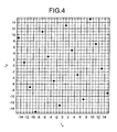
- FIG. 4 is an example of a signal point arrangement of the 16RQAM mapping obtained by applying the expression (4) to the 16QAM mapping depicted in FIG. 3 .
- each of the I-axis values and Q-axis values in FIG. 3 is multiplied by a value of an expression (6) below.
- each of the I-axis values and Q-axis values in FIG. 4 is multiplied by a value of an expression (7) below.
- FIGS. 3 and 4 depict values before multiplication of the respective values for the purpose of explanation.
- FIG. 4 is an example of a signal point arrangement of the mapping I ⁇ indicating the I-axis information component of the sub-carrier ⁇ and I ⁇ indicating the I-axis information component of the sub-carrier ⁇
- similar signal point arrangement may be applied to the mapping of Q ⁇ indicating the Q-axis information component of the sub-carrier ⁇ and Q ⁇ indicating the Q-axis information component of the sub-carrier ⁇ .
- the mapping unit 104 maps the I-axis information component S13 of the sub-carrier ⁇ inputted by the S/P 102 (corresponding to I ⁇ in FIG. 4 ) and the I-axis information component S14 of the sub-carrier ⁇ inputted by the S/P 102 (corresponding to I ⁇ in FIG. 4 ) into I-axis frequency-amplitude components of the respective sub-carriers according to the RQAM mapping illustrated in FIG. 4 .
- the mapping unit 105 maps the Q-axis information component S15 of the sub-carrier ⁇ and the Q-axis information component S16 of the sub-carrier ⁇ inputted by the S/P 103 into Q-axis frequency components of the respective sub-carriers according to the RQAM mapping illustrated in FIG. 4 .
- the conventional QAM modulation system illustrated in FIG. 3 maps an inputted information bit series into an I-axis and a Q-axis of a sub-carrier. That is, for example, in the conventional 16QAM modulation system, an information bit series in units of 4-bit is inputted first.
- the 4-bit information string is distributed by the S/P into two components, which are the I-axis information component of a frequency and the Q-axis information component of a frequency.
- the I-axis information component and the Q-axis information component are then mapped by the 16QAM mapping illustrated in FIG. 3 into the I-axis frequency-amplitude component and the Q-axis frequency-amplitude component for each sub-carrier.
- the modulation system according to the present embodiment illustrated in FIG. 4 performs a mapping in such combinations between the I-axis of the sub-carrier ⁇ and the I-axis of the sub-carrier ⁇ and between the Q-axis of the sub-carrier ⁇ and the Q-axis of the sub-carrier ⁇ in such a manner to straddle the two sub-carriers (the sub-carrier ⁇ and the sub-carrier ⁇ ).
- mapping is performed on not a single frequency but on a plurality of frequencies.
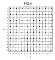
- FIG. 5 depicts a signal point arrangement of a conventional 64QAM mapping.
- FIG. 6 is an example of a signal point arrangement of a 64RQAM mapping obtained by applying the expression (5) to the 64QAM mapping depicted in FIG. 5 .
- each of the I-axis values and Q-axis values in FIG. 5 is multiplied by a value of an expression (8) below.
- each of the I-axis values and Q-axis values in FIG. 6 is multiplied by a value of an expression (9) below.
- FIGS. 5 and 6 depict values before the multiplication of the respective values for the purpose of explanation.
- the applicable mapping system is not limited to the 16QAM mapping or the 64QAM mapping, but for example, it may be applied to 256QAM and the like in which one symbol is converted into multivalued 8-bit.
- FIG. 7 is a schematic diagram of an image of a received signal by the conventional 16QAM mapping.
- FIG. 8 is a schematic diagram of an image of a received signal by the 16RQAM mapping according to the first embodiment.
- a received signal may vary among the sub-carriers by about 10 dB to 20 dB in a multipath environment.
- the communication characteristics vary for each sub-carrier in the conventional 16QAM modulation system as illustrated in FIG. 7 . That is, a characteristic difference between a sub-carrier with superior communication characteristics and a sub-carrier with inferior communication characteristics may occasionally appear in the extreme.
- the diversity effect may be obtained as illustrated in FIG. 8 , and thus a distance between received signal points can be extended. Accordingly, the communication characteristics can be improved.
- FIG. 9 is an example of communication characteristics (BER (Bit Error Rate) characteristics) of a 16RQAM mapping obtained as a result of an evaluation by computer simulation.
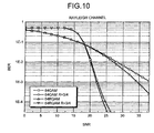
- FIG. 10 is an example of BER characteristics of a 64RQAM mapping.
- FIGS. 9 and 10 an evaluation is performed assuming that a transmission path is in a frequency selective fading environment, that is, the transmission path has Rayleigh distribution characteristics on a frequency axis.
- the 16QAM modulation and the 64QAM modulation are selected as the conventional technique and a result of comparison with the 16RQAM the 64RQAM is indicated in FIGS. 9 and 10 .
- FIGS. 9 and 10 depict two cases, that is, a case without error correction and a case using a convolutional code (with a coding rate of 3/4).
- the horizontal axis in FIGS. 9 and 10 indicates SNR (Signal to Noise Ratio) and the vertical axis indicates BER.
- the communication characteristics are improved as compared to the conventional modulation system due to the diversity effect.
- same characteristics as those of the conventional modulation system appear in an AWGN (Additive white Gaussian noise) environment.
- the transmission device can map transmitting signals in such a manner to straddle a plurality of sub-carriers in multi-carrier communications by a mapping system provided by modifying the conventional QAM mapping. Therefore, the diversity effect and maultivalues may be achieved at the same time and the communication characteristics in the multipath environment may be improved. That is, by changing the conventional QAM mapping for a transmission device to the RQAM mapping, same characteristics as those of the QAM modulation may be obtained in the AWGN environment and characteristics superior to those of the QAM modulation may be obtained in the multipath environment due to the diversity effect.
- a transmission device spreads inputted signals in a frequency direction and in a time direction by interleaving and then performs the RQAM mapping according to the first embodiment.
- FIG. 11 is a block diagram of a transmission device 2 according to the second embodiment.
- the transmission device 2 includes an interleaving unit 21, the RQAM modulating unit 11, the IFFT 12, the DAC 13, the LPF 14, the Mixer 15, the BPF 16, the antenna 17, and the LOCAL 18.
- the second embodiment is different from the first embodiment in that the interleaving unit 21 is added to the transmission device.
- Other configurations and functions of the second embodiment are identical to those illustrated in FIG. 1 , which is a block diagram of the configuration of the transmission device 1 according to the first embodiment, and thus like reference numerals are denoted to like elements and explanations thereof will be omitted.
- the interleaving unit 21 is a block for spreading an inputted signal in a frequency direction and in a time direction. This signal spreading may prevent continuous bit strings from being mapped into the same sub-carrier. The diversity effect is thus expected to be obtained more easily.
- a signal S22 in FIG. 11 indicates a bit string obtained by interleaving the signal S1 as an information bit series inputted to the transmission device 2.
- a transmission device performs an error correction coding process to inputted signals and then performs the RQAM mapping according to the first embodiment.
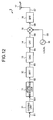
- FIG. 12 is a block diagram of a transmission device 3 according to a third embodiment. As illustrated in FIG. 3 , the transmission device 3 includes a coding unit 31, the RQAM modulating unit 11, the IFFT 12, the DAC 13, the LPF 14, the Mixer 15, the BPF 16, the antenna 17, and the LOCAL 18.
- the third embodiment is different from the first embodiment in that the coding unit 31 is added to the transmission device.
- Other configurations and functions of the third embodiment are identical to those illustrated in FIG. 1 , which is a block diagram of the configuration of the transmission device 1 according to the first embodiment, and thus like reference numerals are denoted to like elements and explanations thereof will be omitted.
- the coding unit 31 performs an error correction coding process to inputted signals. Accordingly, when an error occurs in a transmission path, the error may be corrected at a receiving side. This may reduce BER and an increase in channel capacity and a decrease in communication delay are expected.
- a signal S31 illustrated in FIG. 11 indicates a bit string obtained by error correction coding the signal S1 as an information bit series inputted to the transmission device 3.
- a transmission device applies an RQAM mapping to single carrier communication.
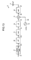
- FIG. 13 is a block diagram of a transmission device 4 according to the fourth embodiment. As illustrated in FIG. 4 , the transmission device 4 includes an RQAM modulating unit 41, an LPF 42, the DAC 13, the LPF 14, the Mixer 15, the BPF 16, the antenna 17, and the LOCAL 18.
- the third embodiment is different from the first embodiment in a function of the RQAM modulating unit 41 and the LPF 42 instead of the IFFT 12.
- Other configurations and functions of the fourth embodiment are identical to those illustrated in FIG. 1 , which is a block diagram of the configuration of the transmission device 1 according to the first embodiment, and thus like reference numerals are denoted to like elements and explanations thereof will be omitted.
- the RQAM modulating unit 41 performs an RQAM mapping on a transmitting signal in such a manner to straddle a plurality of symbols transmitted by single carrier.
- the RQAM modulating unit 11 according to the first embodiment performs the RQAM mapping on a transmitting signal in such a manner to straddle a plurality of sub-carriers in multi-carrier communications to aim at the diversity effect in the frequency direction.
- the RQAM modulating unit 41 according to the fourth embodiment aims at the diversity effect in the time direction.
- the RQAM modulation system is effective even for single carrier when a transmission path varies at a higher speed than the communication time.
- the LPF 42 is a block for shaping a waveform of a square signal inputted by the RQAM modulating unit 41 for attenuating a harmonic component of a frequency.
- a signal S41 in FIG. 13 indicates a time signal outputted as a result of the RQAM mapping.
- a signal S42 indicates a signal whose waveform is shaped by the LPF 42.
- the fourth embodiment may be configured to perform an interleave process with an aim of eliminating correlation in the time direction as described in the second embodiment, or may be configured to perform a coding process for performing error correction on a receiving side as described in the third embodiment.
- the transmission device and the modulation system according to the present invention are useful as a transmission device and a modulation system in a wireless communication system with varying transmission paths such as in a multipath environment, and are particularly applicable to a transmission device and a modulation system using multi-carriers.
Landscapes
- Engineering & Computer Science (AREA)
- Signal Processing (AREA)
- Computer Networks & Wireless Communication (AREA)
- Digital Transmission Methods That Use Modulated Carrier Waves (AREA)
Applications Claiming Priority (2)
| Application Number | Priority Date | Filing Date | Title |
|---|---|---|---|
| JP2008021301 | 2008-01-31 | ||
| PCT/JP2009/051500 WO2009096488A1 (ja) | 2008-01-31 | 2009-01-29 | 送信装置および変調方法 |
Publications (3)
| Publication Number | Publication Date |
|---|---|
| EP2249536A1 true EP2249536A1 (de) | 2010-11-10 |
| EP2249536A4 EP2249536A4 (de) | 2013-08-21 |
| EP2249536B1 EP2249536B1 (de) | 2018-12-12 |
Family
ID=40912833
Family Applications (1)
| Application Number | Title | Priority Date | Filing Date |
|---|---|---|---|
| EP09706325.9A Active EP2249536B1 (de) | 2008-01-31 | 2009-01-29 | Übertragungsvorrichtung und modulationsverfahren |
Country Status (5)
| Country | Link |
|---|---|
| US (1) | US8548094B2 (de) |
| EP (1) | EP2249536B1 (de) |
| JP (1) | JP5213879B2 (de) |
| CN (1) | CN101933305B (de) |
| WO (1) | WO2009096488A1 (de) |
Families Citing this family (3)
| Publication number | Priority date | Publication date | Assignee | Title |
|---|---|---|---|---|
| US8542769B2 (en) * | 2011-06-09 | 2013-09-24 | St-Ericsson Sa | High output power digital TX |
| DE102016102005B4 (de) * | 2016-02-04 | 2018-08-02 | Rheinisch-Westfälische Technische Hochschule Aachen (RWTH) | Schaltungsanordnung und Verfahren zur Erzeugung eines hochfrequenten, analogen Sendesignals |
| CN116232537A (zh) * | 2021-12-02 | 2023-06-06 | 华为技术有限公司 | 通信方法及装置 |
Family Cites Families (20)
| Publication number | Priority date | Publication date | Assignee | Title |
|---|---|---|---|---|
| FR2539261B1 (fr) * | 1983-01-07 | 1989-07-13 | Telecommunications Sa | Emetteur pour faisceaux hertziens numeriques a multi-etats |
| US5379322A (en) * | 1992-01-07 | 1995-01-03 | Sanyo Electric Co., Ltd. | Baseband signal generator for digital modulator |
| US5412351A (en) * | 1993-10-07 | 1995-05-02 | Nystrom; Christian | Quadrature local oscillator network |
| JP4053972B2 (ja) * | 1997-12-16 | 2008-02-27 | 株式会社東芝 | 無線通信装置とその直交振幅復調回路 |
| DE69916151T2 (de) * | 1998-01-30 | 2005-04-21 | Matsushita Electric Industrial Co Ltd | Datenübertragung mit einer Zusammensetzung von Modulationsarten |
| JP3362009B2 (ja) * | 1999-03-01 | 2003-01-07 | シャープ株式会社 | スペクトル拡散通信装置 |
| US6307894B2 (en) * | 1999-05-25 | 2001-10-23 | Conexant Systems, Inc. | Power amplification using a direct-upconverting quadrature mixer topology |
| US6628727B1 (en) * | 2000-01-10 | 2003-09-30 | Syncomm Technology Corporation | Apparatus and method for performing π/4-DQPSK baseband modulation based on a signal mapping to be simplified |
| US6728527B2 (en) * | 2001-07-10 | 2004-04-27 | Asulab S.A. | Double up-conversion modulator |
| US7154936B2 (en) * | 2001-12-03 | 2006-12-26 | Qualcomm, Incorporated | Iterative detection and decoding for a MIMO-OFDM system |
| US6606010B1 (en) * | 2002-01-30 | 2003-08-12 | The Aerospace Corporation | Quadrature vestigial sideband digital communications method |
| US7379509B2 (en) * | 2002-08-19 | 2008-05-27 | Lawrence Livermore National Security, Llc | Digital intermediate frequency QAM modulator using parallel processing |
| WO2004038973A1 (ja) * | 2002-10-23 | 2004-05-06 | Hitachi Kokusai Electric Inc. | 送信機 |
| US7003716B2 (en) * | 2002-12-26 | 2006-02-21 | Zydas Technology Corp. | Method and apparatus for using multi-dimensional trellis codes over multi-path channels |
| WO2006002550A1 (en) * | 2004-07-07 | 2006-01-12 | Nortel Networks Limited | System and method for mapping symbols for mimo transmission |
| US7078981B2 (en) * | 2004-07-27 | 2006-07-18 | Lucent Technologies Inc. | 16 QAM modulator and method of 16 QAM modulation |
| US7646801B2 (en) * | 2006-01-26 | 2010-01-12 | Alcatel-Lucent Usa Inc. | Method and apparatus for spreading and modulating communication signals |
| CA2576778C (en) * | 2006-02-07 | 2014-09-02 | Xinping Huang | Self-calibrating multi-port circuit and method |
| US7609779B2 (en) * | 2006-02-27 | 2009-10-27 | Freescale Semiconductor, Inc. | RF transmitter with interleaved IQ modulation |
| JP4800096B2 (ja) * | 2006-04-21 | 2011-10-26 | ルネサスエレクトロニクス株式会社 | 周波数ホッピング通信用ic |
-
2009
- 2009-01-29 CN CN2009801036421A patent/CN101933305B/zh active Active
- 2009-01-29 WO PCT/JP2009/051500 patent/WO2009096488A1/ja not_active Ceased
- 2009-01-29 US US12/865,526 patent/US8548094B2/en active Active
- 2009-01-29 EP EP09706325.9A patent/EP2249536B1/de active Active
- 2009-01-29 JP JP2009551579A patent/JP5213879B2/ja active Active
Also Published As
| Publication number | Publication date |
|---|---|
| US8548094B2 (en) | 2013-10-01 |
| CN101933305A (zh) | 2010-12-29 |
| JP5213879B2 (ja) | 2013-06-19 |
| WO2009096488A1 (ja) | 2009-08-06 |
| US20110007840A1 (en) | 2011-01-13 |
| JPWO2009096488A1 (ja) | 2011-05-26 |
| CN101933305B (zh) | 2013-08-07 |
| EP2249536A4 (de) | 2013-08-21 |
| EP2249536B1 (de) | 2018-12-12 |
Similar Documents
| Publication | Publication Date | Title |
|---|---|---|
| US9083444B2 (en) | Chirp spread spectrum system and method | |
| US9749167B2 (en) | Transmitting apparatus and transmitting method | |
| US10404839B2 (en) | Signal field encoding in a high efficiency wireless local area network (WLAN) data unit | |
| EP3503489B1 (de) | Modulationsverfahren, demodulationsverfahren, zugehörige vorrichtung und system | |
| US10461984B2 (en) | Transmission method, transmission device, reception method, and reception device | |
| US11258651B2 (en) | Transmission method, transmission device, reception method, and reception device | |
| US8588153B2 (en) | Method and apparatus for transmitting uplink control channel in a mobile communication system | |
| EP2249536B1 (de) | Übertragungsvorrichtung und modulationsverfahren | |
| US10659276B2 (en) | Transmission method, transmission device, reception method, and reception device | |
| Ndujiuba et al. | Dynamic Differential Modulation of Sub-Carriers in OFDM | |
| KR20100004051A (ko) | 순환 부캐리어 천이를 이용한 송신 안테나 다이버시티 전송 방법 및 장치 | |
| JP4863262B2 (ja) | 送信機,通信システム及び送信方法 | |
| JP2008160579A (ja) | 無線通信装置および無線通信方法 | |
| JP5473568B2 (ja) | 送受信システム、信号送信装置、及び信号受信装置 | |
| KR100637710B1 (ko) | 최대전력 대 평균전력비 및/또는 연산량 감소를 위한선택사상기법의 직교 주파수 분할 다중 반송파 통신 방법 | |
| Alasswi et al. | Performance Analysis of MIMO-OFDM Systems under Different Modulation Schemes and Channel Conditions Using Various Transform Techniques | |
| JP5207517B2 (ja) | ディジタル変調方法、ディジタル変調回路、ディジタル復調回路、およびディジタル伝送システム | |
| JP2014039091A (ja) | 情報伝達手段および情報伝達装置 |
Legal Events
| Date | Code | Title | Description |
|---|---|---|---|
| PUAI | Public reference made under article 153(3) epc to a published international application that has entered the european phase |
Free format text: ORIGINAL CODE: 0009012 |
|
| 17P | Request for examination filed |
Effective date: 20100820 |
|
| AK | Designated contracting states |
Kind code of ref document: A1 Designated state(s): AT BE BG CH CY CZ DE DK EE ES FI FR GB GR HR HU IE IS IT LI LT LU LV MC MK MT NL NO PL PT RO SE SI SK TR |
|
| AX | Request for extension of the european patent |
Extension state: AL BA RS |
|
| DAX | Request for extension of the european patent (deleted) | ||
| A4 | Supplementary search report drawn up and despatched |
Effective date: 20130718 |
|
| RIC1 | Information provided on ipc code assigned before grant |
Ipc: H04L 27/36 20060101AFI20130712BHEP Ipc: H04J 11/00 20060101ALI20130712BHEP Ipc: H04L 27/34 20060101ALI20130712BHEP |
|
| 17Q | First examination report despatched |
Effective date: 20160721 |
|
| STAA | Information on the status of an ep patent application or granted ep patent |
Free format text: STATUS: EXAMINATION IS IN PROGRESS |
|
| REG | Reference to a national code |
Ref country code: DE Ref legal event code: R079 Ref document number: 602009056155 Country of ref document: DE Free format text: PREVIOUS MAIN CLASS: H04L0027360000 Ipc: H04L0005000000 |
|
| GRAP | Despatch of communication of intention to grant a patent |
Free format text: ORIGINAL CODE: EPIDOSNIGR1 |
|
| STAA | Information on the status of an ep patent application or granted ep patent |
Free format text: STATUS: GRANT OF PATENT IS INTENDED |
|
| RIC1 | Information provided on ipc code assigned before grant |
Ipc: H04L 27/34 20060101ALI20180531BHEP Ipc: H04L 5/00 20060101AFI20180531BHEP Ipc: H04L 27/36 20060101ALI20180531BHEP |
|
| INTG | Intention to grant announced |
Effective date: 20180622 |
|
| GRAS | Grant fee paid |
Free format text: ORIGINAL CODE: EPIDOSNIGR3 |
|
| GRAA | (expected) grant |
Free format text: ORIGINAL CODE: 0009210 |
|
| STAA | Information on the status of an ep patent application or granted ep patent |
Free format text: STATUS: THE PATENT HAS BEEN GRANTED |
|
| AK | Designated contracting states |
Kind code of ref document: B1 Designated state(s): AT BE BG CH CY CZ DE DK EE ES FI FR GB GR HR HU IE IS IT LI LT LU LV MC MK MT NL NO PL PT RO SE SI SK TR |
|
| REG | Reference to a national code |
Ref country code: GB Ref legal event code: FG4D |
|
| REG | Reference to a national code |
Ref country code: CH Ref legal event code: EP |
|
| REG | Reference to a national code |
Ref country code: AT Ref legal event code: REF Ref document number: 1077404 Country of ref document: AT Kind code of ref document: T Effective date: 20181215 |
|
| REG | Reference to a national code |
Ref country code: DE Ref legal event code: R096 Ref document number: 602009056155 Country of ref document: DE |
|
| REG | Reference to a national code |
Ref country code: IE Ref legal event code: FG4D |
|
| REG | Reference to a national code |
Ref country code: NL Ref legal event code: MP Effective date: 20181212 |
|
| REG | Reference to a national code |
Ref country code: LT Ref legal event code: MG4D |
|
| PG25 | Lapsed in a contracting state [announced via postgrant information from national office to epo] |
Ref country code: LT Free format text: LAPSE BECAUSE OF FAILURE TO SUBMIT A TRANSLATION OF THE DESCRIPTION OR TO PAY THE FEE WITHIN THE PRESCRIBED TIME-LIMIT Effective date: 20181212 Ref country code: FI Free format text: LAPSE BECAUSE OF FAILURE TO SUBMIT A TRANSLATION OF THE DESCRIPTION OR TO PAY THE FEE WITHIN THE PRESCRIBED TIME-LIMIT Effective date: 20181212 Ref country code: HR Free format text: LAPSE BECAUSE OF FAILURE TO SUBMIT A TRANSLATION OF THE DESCRIPTION OR TO PAY THE FEE WITHIN THE PRESCRIBED TIME-LIMIT Effective date: 20181212 Ref country code: BG Free format text: LAPSE BECAUSE OF FAILURE TO SUBMIT A TRANSLATION OF THE DESCRIPTION OR TO PAY THE FEE WITHIN THE PRESCRIBED TIME-LIMIT Effective date: 20190312 Ref country code: LV Free format text: LAPSE BECAUSE OF FAILURE TO SUBMIT A TRANSLATION OF THE DESCRIPTION OR TO PAY THE FEE WITHIN THE PRESCRIBED TIME-LIMIT Effective date: 20181212 Ref country code: ES Free format text: LAPSE BECAUSE OF FAILURE TO SUBMIT A TRANSLATION OF THE DESCRIPTION OR TO PAY THE FEE WITHIN THE PRESCRIBED TIME-LIMIT Effective date: 20181212 Ref country code: NO Free format text: LAPSE BECAUSE OF FAILURE TO SUBMIT A TRANSLATION OF THE DESCRIPTION OR TO PAY THE FEE WITHIN THE PRESCRIBED TIME-LIMIT Effective date: 20190312 |
|
| REG | Reference to a national code |
Ref country code: AT Ref legal event code: MK05 Ref document number: 1077404 Country of ref document: AT Kind code of ref document: T Effective date: 20181212 |
|
| PG25 | Lapsed in a contracting state [announced via postgrant information from national office to epo] |
Ref country code: GR Free format text: LAPSE BECAUSE OF FAILURE TO SUBMIT A TRANSLATION OF THE DESCRIPTION OR TO PAY THE FEE WITHIN THE PRESCRIBED TIME-LIMIT Effective date: 20190313 Ref country code: SE Free format text: LAPSE BECAUSE OF FAILURE TO SUBMIT A TRANSLATION OF THE DESCRIPTION OR TO PAY THE FEE WITHIN THE PRESCRIBED TIME-LIMIT Effective date: 20181212 |
|
| PG25 | Lapsed in a contracting state [announced via postgrant information from national office to epo] |
Ref country code: NL Free format text: LAPSE BECAUSE OF FAILURE TO SUBMIT A TRANSLATION OF THE DESCRIPTION OR TO PAY THE FEE WITHIN THE PRESCRIBED TIME-LIMIT Effective date: 20181212 |
|
| PG25 | Lapsed in a contracting state [announced via postgrant information from national office to epo] |
Ref country code: PL Free format text: LAPSE BECAUSE OF FAILURE TO SUBMIT A TRANSLATION OF THE DESCRIPTION OR TO PAY THE FEE WITHIN THE PRESCRIBED TIME-LIMIT Effective date: 20181212 Ref country code: IT Free format text: LAPSE BECAUSE OF FAILURE TO SUBMIT A TRANSLATION OF THE DESCRIPTION OR TO PAY THE FEE WITHIN THE PRESCRIBED TIME-LIMIT Effective date: 20181212 Ref country code: CZ Free format text: LAPSE BECAUSE OF FAILURE TO SUBMIT A TRANSLATION OF THE DESCRIPTION OR TO PAY THE FEE WITHIN THE PRESCRIBED TIME-LIMIT Effective date: 20181212 Ref country code: PT Free format text: LAPSE BECAUSE OF FAILURE TO SUBMIT A TRANSLATION OF THE DESCRIPTION OR TO PAY THE FEE WITHIN THE PRESCRIBED TIME-LIMIT Effective date: 20190412 |
|
| PG25 | Lapsed in a contracting state [announced via postgrant information from national office to epo] |
Ref country code: SK Free format text: LAPSE BECAUSE OF FAILURE TO SUBMIT A TRANSLATION OF THE DESCRIPTION OR TO PAY THE FEE WITHIN THE PRESCRIBED TIME-LIMIT Effective date: 20181212 Ref country code: EE Free format text: LAPSE BECAUSE OF FAILURE TO SUBMIT A TRANSLATION OF THE DESCRIPTION OR TO PAY THE FEE WITHIN THE PRESCRIBED TIME-LIMIT Effective date: 20181212 Ref country code: RO Free format text: LAPSE BECAUSE OF FAILURE TO SUBMIT A TRANSLATION OF THE DESCRIPTION OR TO PAY THE FEE WITHIN THE PRESCRIBED TIME-LIMIT Effective date: 20181212 Ref country code: IS Free format text: LAPSE BECAUSE OF FAILURE TO SUBMIT A TRANSLATION OF THE DESCRIPTION OR TO PAY THE FEE WITHIN THE PRESCRIBED TIME-LIMIT Effective date: 20190412 |
|
| REG | Reference to a national code |
Ref country code: CH Ref legal event code: PL |
|
| REG | Reference to a national code |
Ref country code: DE Ref legal event code: R097 Ref document number: 602009056155 Country of ref document: DE |
|
| PG25 | Lapsed in a contracting state [announced via postgrant information from national office to epo] |
Ref country code: LU Free format text: LAPSE BECAUSE OF NON-PAYMENT OF DUE FEES Effective date: 20190129 |
|
| REG | Reference to a national code |
Ref country code: BE Ref legal event code: MM Effective date: 20190131 |
|
| PLBE | No opposition filed within time limit |
Free format text: ORIGINAL CODE: 0009261 |
|
| STAA | Information on the status of an ep patent application or granted ep patent |
Free format text: STATUS: NO OPPOSITION FILED WITHIN TIME LIMIT |
|
| REG | Reference to a national code |
Ref country code: IE Ref legal event code: MM4A |
|
| PG25 | Lapsed in a contracting state [announced via postgrant information from national office to epo] |
Ref country code: AT Free format text: LAPSE BECAUSE OF FAILURE TO SUBMIT A TRANSLATION OF THE DESCRIPTION OR TO PAY THE FEE WITHIN THE PRESCRIBED TIME-LIMIT Effective date: 20181212 Ref country code: MC Free format text: LAPSE BECAUSE OF FAILURE TO SUBMIT A TRANSLATION OF THE DESCRIPTION OR TO PAY THE FEE WITHIN THE PRESCRIBED TIME-LIMIT Effective date: 20181212 Ref country code: SI Free format text: LAPSE BECAUSE OF FAILURE TO SUBMIT A TRANSLATION OF THE DESCRIPTION OR TO PAY THE FEE WITHIN THE PRESCRIBED TIME-LIMIT Effective date: 20181212 Ref country code: DK Free format text: LAPSE BECAUSE OF FAILURE TO SUBMIT A TRANSLATION OF THE DESCRIPTION OR TO PAY THE FEE WITHIN THE PRESCRIBED TIME-LIMIT Effective date: 20181212 |
|
| 26N | No opposition filed |
Effective date: 20190913 |
|
| PG25 | Lapsed in a contracting state [announced via postgrant information from national office to epo] |
Ref country code: BE Free format text: LAPSE BECAUSE OF NON-PAYMENT OF DUE FEES Effective date: 20190131 |
|
| PG25 | Lapsed in a contracting state [announced via postgrant information from national office to epo] |
Ref country code: CH Free format text: LAPSE BECAUSE OF NON-PAYMENT OF DUE FEES Effective date: 20190131 Ref country code: LI Free format text: LAPSE BECAUSE OF NON-PAYMENT OF DUE FEES Effective date: 20190131 |
|
| PG25 | Lapsed in a contracting state [announced via postgrant information from national office to epo] |
Ref country code: IE Free format text: LAPSE BECAUSE OF NON-PAYMENT OF DUE FEES Effective date: 20190129 |
|
| PG25 | Lapsed in a contracting state [announced via postgrant information from national office to epo] |
Ref country code: TR Free format text: LAPSE BECAUSE OF FAILURE TO SUBMIT A TRANSLATION OF THE DESCRIPTION OR TO PAY THE FEE WITHIN THE PRESCRIBED TIME-LIMIT Effective date: 20181212 |
|
| PG25 | Lapsed in a contracting state [announced via postgrant information from national office to epo] |
Ref country code: MT Free format text: LAPSE BECAUSE OF NON-PAYMENT OF DUE FEES Effective date: 20190129 |
|
| PG25 | Lapsed in a contracting state [announced via postgrant information from national office to epo] |
Ref country code: CY Free format text: LAPSE BECAUSE OF FAILURE TO SUBMIT A TRANSLATION OF THE DESCRIPTION OR TO PAY THE FEE WITHIN THE PRESCRIBED TIME-LIMIT Effective date: 20181212 |
|
| PG25 | Lapsed in a contracting state [announced via postgrant information from national office to epo] |
Ref country code: HU Free format text: LAPSE BECAUSE OF FAILURE TO SUBMIT A TRANSLATION OF THE DESCRIPTION OR TO PAY THE FEE WITHIN THE PRESCRIBED TIME-LIMIT; INVALID AB INITIO Effective date: 20090129 |
|
| PG25 | Lapsed in a contracting state [announced via postgrant information from national office to epo] |
Ref country code: MK Free format text: LAPSE BECAUSE OF FAILURE TO SUBMIT A TRANSLATION OF THE DESCRIPTION OR TO PAY THE FEE WITHIN THE PRESCRIBED TIME-LIMIT Effective date: 20181212 |
|
| P01 | Opt-out of the competence of the unified patent court (upc) registered |
Effective date: 20230512 |
|
| PGFP | Annual fee paid to national office [announced via postgrant information from national office to epo] |
Ref country code: GB Payment date: 20251211 Year of fee payment: 18 |
|
| PGFP | Annual fee paid to national office [announced via postgrant information from national office to epo] |
Ref country code: FR Payment date: 20251128 Year of fee payment: 18 |
|
| PGFP | Annual fee paid to national office [announced via postgrant information from national office to epo] |
Ref country code: DE Payment date: 20251203 Year of fee payment: 18 |