EP2248637A1 - Anordnung zum manuellen Schneiden von Lebensmitteln - Google Patents
Anordnung zum manuellen Schneiden von Lebensmitteln Download PDFInfo
- Publication number
- EP2248637A1 EP2248637A1 EP09159811A EP09159811A EP2248637A1 EP 2248637 A1 EP2248637 A1 EP 2248637A1 EP 09159811 A EP09159811 A EP 09159811A EP 09159811 A EP09159811 A EP 09159811A EP 2248637 A1 EP2248637 A1 EP 2248637A1
- Authority
- EP
- European Patent Office
- Prior art keywords
- slot
- upright
- knife
- board
- guiding
- Prior art date
- Legal status (The legal status is an assumption and is not a legal conclusion. Google has not performed a legal analysis and makes no representation as to the accuracy of the status listed.)
- Withdrawn
Links
- 230000008878 coupling Effects 0.000 claims description 17
- 238000010168 coupling process Methods 0.000 claims description 17
- 238000005859 coupling reaction Methods 0.000 claims description 17
- 239000002783 friction material Substances 0.000 claims description 3
- 239000002861 polymer material Substances 0.000 claims description 3
- 235000008429 bread Nutrition 0.000 abstract description 5
- 229930040373 Paraformaldehyde Natural products 0.000 description 8
- 229920006324 polyoxymethylene Polymers 0.000 description 8
- 238000010276 construction Methods 0.000 description 6
- 239000000463 material Substances 0.000 description 6
- 239000000945 filler Substances 0.000 description 5
- 229910001220 stainless steel Inorganic materials 0.000 description 5
- 239000010935 stainless steel Substances 0.000 description 5
- -1 Polyoxymethylene Polymers 0.000 description 4
- 230000000694 effects Effects 0.000 description 4
- 239000004035 construction material Substances 0.000 description 3
- 230000001154 acute effect Effects 0.000 description 2
- XAGFODPZIPBFFR-UHFFFAOYSA-N aluminium Chemical compound [Al] XAGFODPZIPBFFR-UHFFFAOYSA-N 0.000 description 2
- 229910052782 aluminium Inorganic materials 0.000 description 2
- 235000012813 breadcrumbs Nutrition 0.000 description 2
- 235000021190 leftovers Nutrition 0.000 description 2
- 235000012970 cakes Nutrition 0.000 description 1
- 238000010411 cooking Methods 0.000 description 1
- 230000001419 dependent effect Effects 0.000 description 1
- 235000013372 meat Nutrition 0.000 description 1
- 238000000034 method Methods 0.000 description 1
- 239000004033 plastic Substances 0.000 description 1
- 229920000642 polymer Polymers 0.000 description 1
- 239000012815 thermoplastic material Substances 0.000 description 1
- 235000013311 vegetables Nutrition 0.000 description 1
Images





Classifications
-
- A—HUMAN NECESSITIES
- A47—FURNITURE; DOMESTIC ARTICLES OR APPLIANCES; COFFEE MILLS; SPICE MILLS; SUCTION CLEANERS IN GENERAL
- A47J—KITCHEN EQUIPMENT; COFFEE MILLS; SPICE MILLS; APPARATUS FOR MAKING BEVERAGES
- A47J47/00—Kitchen containers, stands or the like, not provided for in other groups of this subclass; Cutting-boards, e.g. for bread
- A47J47/005—Cutting boards
-
- B—PERFORMING OPERATIONS; TRANSPORTING
- B26—HAND CUTTING TOOLS; CUTTING; SEVERING
- B26B—HAND-HELD CUTTING TOOLS NOT OTHERWISE PROVIDED FOR
- B26B29/00—Guards or sheaths or guides for hand cutting tools; Arrangements for guiding hand cutting tools
- B26B29/06—Arrangements for guiding hand cutting tools
- B26B29/063—Food related applications
-
- B—PERFORMING OPERATIONS; TRANSPORTING
- B26—HAND CUTTING TOOLS; CUTTING; SEVERING
- B26B—HAND-HELD CUTTING TOOLS NOT OTHERWISE PROVIDED FOR
- B26B3/00—Hand knives with fixed blades
Definitions
- the upright Due to the distance between the first slot and the second slot, the upright essentially provides a first and second guiding part in the through-opening, which first and second guiding parts are arranged at a distance to provide a straight and stable guiding of the knife.
- the first and second guiding parts are both arranged on the same side of the board, and in particular on the same side of the foodstuff to be cut.
- the distance between the front and rear can be relatively small, for example smaller than 10 cm, preferably smaller than 8 cm, preferably smaller than 6 cm.
- the distance between the front and rear is larger than 2 cm, preferably larger than 4 cm.
- the upright for guiding the knife only requires a small area of the worktop, preferably smaller than the width of the foodstuff like bread or cake.
- the first and the second slot have a larger width at or near an upper side of the slot and/or the upright, wherein the width extends over a small length in the longitudinal direction of the upright.
- the larger width of the first and the second slot allows a knife comprising a projection being inserted through the upright for usage.
- the projection needs to be positioned firstly in front of the larger width of the first slot, and, after the projection being run through the first slot, to be positioned secondly in front of the larger width of the second slot, subsequently the projection can be run through the second slot as well.
- the recess comprises an opening surface for moving the upright into and out of the recess, which opening surface is substantially situated parallel to and/or below a plane through the upper side of the support element.
- FIG 1 shows a schematic top-view of a first embodiment of the invention, called a "hotel-slicer", for manually cutting foodstuff, such as bread or cake.
- This exemplary embodiment comprises a board 1 having a surface 2 for supporting the foodstuff.
- the assembly is provided with a single guiding member 3, which extends in a direction substantially perpendicular to the surface 2.
- Said guiding member 3 is placed at a first edge 4 of the board 1, in particular substantially in the centre of this first edge 4, as shown in figures 1 and 3 .
- the guiding member 4 comprises a vertical extending block having a substantially rectangular cross-section, which extend over a distance B from said first edge 4 of the board 1.
- the guiding member 3 is fixed to a bottom plate 9 by means of a screw connection 8.
- the bottom plate 9 is accommodated in a recess at the bottom side of the board 1.
- the guiding member 3 can directly connected to the board 1.
- the board is provided with a groove 13, which is also substantially arranged in the same plane as the slot 5.
- the groove 13 can accommodate the cutting edge 2 of the knife 6, such that the cutting edge 2 can reach below the supporting surface 2 of the board in order to fully cut the foodstuff.
- the knife 6 is at its proximate end provided with and handle 15 which is arranged at an angle ⁇ with respect to the cutting edge 14 of the knife 6.
- the handle 14 is arranged at an acute angle with respect to the cutting edge 14, in particular the acute angle is approximately 67 degrees.
- the knife 6 is provided with a notch 17 for preventing that the knife 6 is not pulled out of the slot 5.
- the distal end part 18 of the knife 6 is provided without the lower cutting edge 14. This smooth edge 19 of the knife 6 may prevent an unwanted cutting action by the knife 6 at the side of the guiding member 3 remote from the board 1.
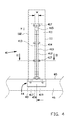
- Figure 4 shows an example of an guiding member or upright 41 to guide a knife (not shown) for manually cutting foodstuff, wherein the upright 41 is attached to a worktop 46 which is typically situated in a kitchen like environment. Therefore, such an upright is made from material which withstands often being cleaned, such as stainless steel, aluminum or a thermoplastic material.
- the first slot 412 and the second slot 422 are provided with a guiding body 413, 423.
- a first guiding body 413 is fixed to the front 411, at the inner side of the upright 41 providing that the first slot 412 becomes narrower.
- the guiding body 413 is typically made from a material such as polyoxymethylene (POM) which is suitable to guide a knife for manually cutting foodstuff.
- POM polyoxymethylene
- the first slot 412 comprises a slot part 415 having a wider width extending over a certain length H of the first slot 412 in the length direction of the upright 41 and over a certain width W of the slot in a direction transverse to the length direction of the upright 41.
- the slot part 415 is arranged to allow the passing of a projection or notch 52 at the distal end of the knife 5, situated at a side opposite the handle side of a knife which will be described with reference to figure 6 .
- the upright 41 according to figure 4 is coupled with the worktop 46 via a support element 44.
- An upper side 65 of the worktop 46 therefore comprises a slot 43 for accommodating the support element 44 which is inserted in the slot 43 in such a manner that the support element 44 abuttingly fits in the slot 43 of the worktop 46.
- Figure 5 shows both the front 411 and the side walls 111,112 according to the description of figure 4 and the rear 421 of the upright 41.
- the second slot 422 is provided with a second guiding body 423.
- This second guiding body 423 comprises a plate 424 and is connected to the rear 421 by means of bolts 427.
- the rear 421 is remote from the front 411 is such a manner as to provide a knife being laterally guided by substantially two guiding bodies 413, 423 which contributes to a straight and stable reciprocating motion of a knife running through the first slot 412 and the second slot 422.
- the distance between the first slot 412 and the second slot 422 is particularly larger than the width of the first slot 412 and the second slot 422.
- the first slot 412 is arranged in line with the second slot 422.
- the knife 50 comprises a handle 51 and a projection 52 situated opposite the handle side of the knife 50, and a blade 53 situated between the handle 51 and the projection 52.
- the projection 52 can be of any shape being able to pass through the upper part 415 of the slot 412, but is preferably cylindrically extending perpendicularly to a plane of a blade 53 of the knife 50.
- each simple, common knife suitable for cutting foodstuff can also be used for running through the first slot 412, however such a knife is able to inadvertently escaping the second slot 422 and the first slot 412 as well.
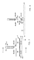
- Figures 7 and 8 show similar parts as in figure 6 , however, the knife 50 is being retracted and the remaining parts are depicted in an exploded view.
- the lowest part of the assembly according to figure 6 is the worktop 46 comprising a slot 43 (not shown in figure 7 ) located between a first side 61 of the worktop 46 and a second side 62 situated opposite the first side 61 of the worktop 46.
- the slot 43 extends, in this example, from a third end 63 of the worktop 46 towards a fourth end 64 situated opposite the third end 63 of the worktop 6.
- the slot 43 forms a recess for accommodating and supporting support element 44 into the worktop 46.
- Support element 44 comprises a profile preferably made from aluminum, a bottom part 145 and filler elements 146, 147 for accommodating and lateral supporting the insert fillers 148, 149 which are preferably made from a plastic.
- the insert filler 148 is to be inserted into the profile between the third side 63 of the worktop 46 and the front 411 of the upright 41 and the insert filler 149 is to be inserted into the profile between the rear 421 of the upright 41 and the fourth side 64 of the worktop 46.
- the upright 41 comprises first coupling means 48 to couple the upright 41 with a worktop 46 via the support element 44.
- the upright 41 comprises therefore at the front 411 end side coupling pins 181, 182 and at the rear 421 end side coupling pins 183, 184.
- the coupling pins 181, 182, 183, 184 are suitable to engage with matching coupling slots 141, 142, 143, 144 respectively, at least a part of these coupling slots 141, 142, 143, 144 comprising the properties of a bayonet locking type comprising a resilient portion biasing the pins within their slots.
- the above described method is reversed.
- the upright 41 can be cleaned up by removing it from the worktop 46 to provide accommodating the area where the upright was installed to other, kitchen like, activities.
- the upright 41 can be cleaned and stored in a kitchen like cabinet comprising more stored articles.
- the bayonet type of connecting the upright 41 with the worktop 46 can also be used for connecting the guiding member 3 with the board 1 of figures 1 , 2 and 3 .
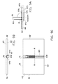
- Figure 9A, 9B and 9C show a further exemplary embodiment of the upright 91 that can be stored in a recess 97 accommodating the upright in a stored position.
- the recess 97 comprises a bottom wall 970, a front wall 971, a first side wall 972, a rear wall 973 and a second side wall 974, these walls 970, 971, 972, 973, 974 forming a box 975 which is open at the top side 976.
- the surface through the top side 976 of the box 975 is substantially parallel with and situated just below the upper side 65 of the worktop 60.
- Figure 6A and 6C show a centerline R which is situated at or near but parallel to an intersection line arising from a plane through the front wall 911 of the upright 91 intersecting with the upper plane 65 of the worktop 60.
- the upright 91 is, in this example, provided with hinging means (not shown) for which hinging said upright 91 around the centerline R.
- the hinging means of the upright 91 is located at or near an intersection line of the plane through the bottom side of the upright 91 and the plane through the front 911 of the upright, so that the intersection line substantially coincides with the centerline R.
- Figure 11 shows a further exemplary embodiment of an assembly according to the invention.
- the wall 211 and the upright or guiding member 203 are formed as one unity.
- the front side of the slot 205 is arranged substantially in the plane of the wall 211.
- the board 201 is provided with a groove 213, which is also substantially arranged in the same plane as the slot 205.
- the groove 213 can accommodate the cutting edge of the knife as explained above.
- the board 201 is provided with a further groove 214 in front of the wall 211.
- the further groove 214 is arranged to collect leftovers or residues of the foodstuff released by the cutting action, such as bread crumbs. Due to this further groove 214 it is substantially prevented that residues of the cutting reach the slot 205, and thus may substantially prevent pollution of the slot 205.
- Figure 12 shows an exemplary embodiment of an assembly according to the invention where the upright 303 stretches along the whole length of the first edge 304 for providing the slot 305 for guiding a knife, as well as providing a wall for placing the foodstuff against during the cutting action.
- the upright 303 is hingedly attached to the cutting board 301 for rotation of the upright 303 around an axis substantially parallel to the first side 304. When not in use, the upright may be rotated to collapse on top of the cutting board 301.
Landscapes
- Engineering & Computer Science (AREA)
- Food Science & Technology (AREA)
- Life Sciences & Earth Sciences (AREA)
- Forests & Forestry (AREA)
- Mechanical Engineering (AREA)
- Food-Manufacturing Devices (AREA)
Priority Applications (1)
| Application Number | Priority Date | Filing Date | Title |
|---|---|---|---|
| EP09159811A EP2248637A1 (de) | 2009-05-08 | 2009-05-08 | Anordnung zum manuellen Schneiden von Lebensmitteln |
Applications Claiming Priority (1)
| Application Number | Priority Date | Filing Date | Title |
|---|---|---|---|
| EP09159811A EP2248637A1 (de) | 2009-05-08 | 2009-05-08 | Anordnung zum manuellen Schneiden von Lebensmitteln |
Publications (1)
| Publication Number | Publication Date |
|---|---|
| EP2248637A1 true EP2248637A1 (de) | 2010-11-10 |
Family
ID=41168491
Family Applications (1)
| Application Number | Title | Priority Date | Filing Date |
|---|---|---|---|
| EP09159811A Withdrawn EP2248637A1 (de) | 2009-05-08 | 2009-05-08 | Anordnung zum manuellen Schneiden von Lebensmitteln |
Country Status (1)
| Country | Link |
|---|---|
| EP (1) | EP2248637A1 (de) |
Cited By (1)
| Publication number | Priority date | Publication date | Assignee | Title |
|---|---|---|---|---|
| CN102525303A (zh) * | 2012-02-08 | 2012-07-04 | 余胜东 | 自动进给的手动切菜砧板 |
Citations (10)
| Publication number | Priority date | Publication date | Assignee | Title |
|---|---|---|---|---|
| NL61002C (de) * | ||||
| BE454437A (de) | ||||
| US53835A (en) | 1866-04-10 | Improved bread and meat cutter | ||
| GB206009A (en) | 1922-10-27 | 1923-11-01 | George Henry Kirtley | Improvements relating to cutting and slicing machines |
| US2398192A (en) * | 1943-06-18 | 1946-04-09 | Jr John Scheminger | Board for use in slicing thin slices |
| FR2041263A5 (de) * | 1969-04-18 | 1971-01-29 | Birambeau Ets | |
| GB1293073A (en) * | 1970-09-11 | 1972-10-18 | Albert Edward Wardle | Improvements to domestic bread boards |
| US4094221A (en) * | 1976-10-12 | 1978-06-13 | Jacoby Charles E | Cutting board attachment |
| WO2001067939A2 (en) * | 2000-03-14 | 2001-09-20 | Rudolph Martorella | Cutting board |
| NL1034665C2 (nl) * | 2007-11-09 | 2009-05-12 | Qualicasa B V | Snij-inrichting. |
-
2009
- 2009-05-08 EP EP09159811A patent/EP2248637A1/de not_active Withdrawn
Patent Citations (10)
| Publication number | Priority date | Publication date | Assignee | Title |
|---|---|---|---|---|
| NL61002C (de) * | ||||
| BE454437A (de) | ||||
| US53835A (en) | 1866-04-10 | Improved bread and meat cutter | ||
| GB206009A (en) | 1922-10-27 | 1923-11-01 | George Henry Kirtley | Improvements relating to cutting and slicing machines |
| US2398192A (en) * | 1943-06-18 | 1946-04-09 | Jr John Scheminger | Board for use in slicing thin slices |
| FR2041263A5 (de) * | 1969-04-18 | 1971-01-29 | Birambeau Ets | |
| GB1293073A (en) * | 1970-09-11 | 1972-10-18 | Albert Edward Wardle | Improvements to domestic bread boards |
| US4094221A (en) * | 1976-10-12 | 1978-06-13 | Jacoby Charles E | Cutting board attachment |
| WO2001067939A2 (en) * | 2000-03-14 | 2001-09-20 | Rudolph Martorella | Cutting board |
| NL1034665C2 (nl) * | 2007-11-09 | 2009-05-12 | Qualicasa B V | Snij-inrichting. |
Cited By (2)
| Publication number | Priority date | Publication date | Assignee | Title |
|---|---|---|---|---|
| CN102525303A (zh) * | 2012-02-08 | 2012-07-04 | 余胜东 | 自动进给的手动切菜砧板 |
| CN102525303B (zh) * | 2012-02-08 | 2015-05-06 | 温州职业技术学院 | 自动进给的手动切菜砧板 |
Similar Documents
| Publication | Publication Date | Title |
|---|---|---|
| ES2368529T3 (es) | Corte de material rígido y semirígido. | |
| US20020088325A1 (en) | Rip fence with dual locking mechanism | |
| US7146737B2 (en) | Kitchen appliance for slicing various products | |
| US10661461B2 (en) | Food product cutting apparatus having user-selectable horizontal and vertical mounts that provide the same cutting thrust axis orientation | |
| EP1955628B1 (de) | Schneidegerät und Reibeisen für Lebensmittel | |
| US7837137B2 (en) | Holder with shaft element for a device for mincing food | |
| US11130184B2 (en) | Table saw and splinter protection element | |
| US10279490B2 (en) | Utility knife with pivoting head assembly | |
| CA2504244C (en) | Rotary trimmer | |
| US10513047B2 (en) | Meat processing apparatus and methods | |
| EP3213892A1 (de) | Schneidguthalter für gemüsehobel, sowie gemüsehobel | |
| CA2158311C (en) | Cheese slicer | |
| DE3302297C2 (de) | Staubsauger | |
| KR20160059701A (ko) | 3중으로 형성된 주방용 칼 | |
| US20130312581A1 (en) | Adjustable slicer and cutter | |
| DE10049156A1 (de) | Maschine zum Schneiden von Lebensmitteln, insbesondere von Brot | |
| EP2030553A2 (de) | Upright-Staubsauger | |
| JP3742601B2 (ja) | 切断可能な材料を切断するための台所用器具 | |
| KR102439499B1 (ko) | 양면형 도마 | |
| NL1035882C (nl) | Snijwerktuig voor kaas. | |
| KR200197497Y1 (ko) | 도마 | |
| EP2366510A1 (de) | Halteschablone für große frischen Bioproben | |
| JP3875148B2 (ja) | パンチ | |
| KR200315712Y1 (ko) | 무 써는 기구 | |
| CA2792668A1 (en) | Collapsible work bench apparatus |
Legal Events
| Date | Code | Title | Description |
|---|---|---|---|
| PUAI | Public reference made under article 153(3) epc to a published international application that has entered the european phase |
Free format text: ORIGINAL CODE: 0009012 |
|
| AK | Designated contracting states |
Kind code of ref document: A1 Designated state(s): AT BE BG CH CY CZ DE DK EE ES FI FR GB GR HR HU IE IS IT LI LT LU LV MC MK MT NL NO PL PT RO SE SI SK TR |
|
| AX | Request for extension of the european patent |
Extension state: AL BA RS |
|
| STAA | Information on the status of an ep patent application or granted ep patent |
Free format text: STATUS: THE APPLICATION IS DEEMED TO BE WITHDRAWN |
|
| 18D | Application deemed to be withdrawn |
Effective date: 20110511 |