EP2248070B1 - Operationssteuerabbildung, anzeigeeinheit und weissliniendetektionsvorrichtung - Google Patents
Operationssteuerabbildung, anzeigeeinheit und weissliniendetektionsvorrichtung Download PDFInfo
- Publication number
- EP2248070B1 EP2248070B1 EP09706705A EP09706705A EP2248070B1 EP 2248070 B1 EP2248070 B1 EP 2248070B1 EP 09706705 A EP09706705 A EP 09706705A EP 09706705 A EP09706705 A EP 09706705A EP 2248070 B1 EP2248070 B1 EP 2248070B1
- Authority
- EP
- European Patent Office
- Prior art keywords
- white line
- line detection
- region
- allowed
- temperature
- Prior art date
- Legal status (The legal status is an assumption and is not a legal conclusion. Google has not performed a legal analysis and makes no representation as to the accuracy of the status listed.)
- Not-in-force
Links
Images



Classifications
-
- B—PERFORMING OPERATIONS; TRANSPORTING
- B60—VEHICLES IN GENERAL
- B60W—CONJOINT CONTROL OF VEHICLE SUB-UNITS OF DIFFERENT TYPE OR DIFFERENT FUNCTION; CONTROL SYSTEMS SPECIALLY ADAPTED FOR HYBRID VEHICLES; ROAD VEHICLE DRIVE CONTROL SYSTEMS FOR PURPOSES NOT RELATED TO THE CONTROL OF A PARTICULAR SUB-UNIT
- B60W50/00—Details of control systems for road vehicle drive control not related to the control of a particular sub-unit, e.g. process diagnostic or vehicle driver interfaces
- B60W50/08—Interaction between the driver and the control system
- B60W50/14—Means for informing the driver, warning the driver or prompting a driver intervention
-
- G—PHYSICS
- G06—COMPUTING OR CALCULATING; COUNTING
- G06V—IMAGE OR VIDEO RECOGNITION OR UNDERSTANDING
- G06V20/00—Scenes; Scene-specific elements
- G06V20/50—Context or environment of the image
- G06V20/56—Context or environment of the image exterior to a vehicle by using sensors mounted on the vehicle
- G06V20/588—Recognition of the road, e.g. of lane markings; Recognition of the vehicle driving pattern in relation to the road
-
- H—ELECTRICITY
- H04—ELECTRIC COMMUNICATION TECHNIQUE
- H04N—PICTORIAL COMMUNICATION, e.g. TELEVISION
- H04N23/00—Cameras or camera modules comprising electronic image sensors; Control thereof
- H04N23/70—Circuitry for compensating brightness variation in the scene
- H04N23/76—Circuitry for compensating brightness variation in the scene by influencing the image signals
-
- H—ELECTRICITY
- H04—ELECTRIC COMMUNICATION TECHNIQUE
- H04N—PICTORIAL COMMUNICATION, e.g. TELEVISION
- H04N23/00—Cameras or camera modules comprising electronic image sensors; Control thereof
- H04N23/80—Camera processing pipelines; Components thereof
- H04N23/81—Camera processing pipelines; Components thereof for suppressing or minimising disturbance in the image signal generation
Definitions
- the invention generally relates to white line detection. More particularly, the invention relates to a computer program product, a display portion, and a white line detection apparatus that enable a white line detection portion to perform sufficiently within a range where the effect from thermal noise is acceptable.
- Some white line detection apparatuses have been developed that detect white lines on roads based on captured images of the road surface.
- Some white line detection apparatuses according to related art include i) an imaging portion that includes a solid-state image sensor for capturing an image of the road surface, ii) a gain controlling portion that controls the gain when amplifying a road surface image signal generated by the imaging portion, based on the brightness around the vehicle, iii) a white line detection portion that compares the difference between the brightness values of the road and the white line in the amplified road surface image signal with a threshold value and detects the white line based on the result of the comparison, iv) a temperature measuring portion that measures the temperature of the imaging portion, v) a determining portion that determines whether to allow operation of the white line detection portion, and vi) an operation controlling portion that controls the operation of the white line detection portion based on the determination results of the determining portion.
- the reason why the determining portion determines whether to allow operation of the white detection portion based on the temperature of the imaging portion is as follows. That is, thermal electrons are produced in a light receiving portion (i.e., a photodiode) of the solid-state image sensor. The quantity of thermal electrons gradually increases as the temperature of the imaging portion rises. Accordingly, if the temperature of the solid-state image sensor is high, a large quantity of thermal electrons accumulates in the light-receiving portion. If the voltage based on the thermal electrons is amplified by the amplifying portion, a large amount of thermal noise is produced. As a result, the white line detection portion becomes unable to distinguish the white line from the thermal noise so the identifying accuracy of the white line diminishes. Therefore, if the temperature of the image portion exceeds a predetermined temperature, the determining portion according to the related art will not allow the white line detection portion to operate at all.
- FIG. 11 is a view of a white line detection portion control map provided in a determining portion of a white line detection apparatus according to related art.
- the white line detection portion control map uses the gain of the amplifying portion and the temperature of the imaging portion as variables, and includes an allowed region in which operation of the white line detection portion is allowed and a disallowed region in which operation of the white line detection portion is not allowed, based on the variables.
- the operation of the white line detection portion is controlled in accordance with the white line detection portion control map.
- the white line detection portion control map according to the related art is set so that operation of the white line detection portion is not allowed at all if the temperature of the imaging portion becomes equal to or greater than a predetermined temperature, regardless of the gain of the amplifying portion, as shown in FIG. 11 .
- the temperature of the imaging portion increases during the daytime, when it is usually light outside and the gain of the amplifying portion is low. Therefore, it is difficult to imagine a case in which the temperature of the imaging portion and the gain of the amplifying portion are both high. Accordingly, during the daytime when the gain of the amplifying portion is low while the temperature is high, the white line detection apparatus according to the related art may stop operating without performing sufficiently even though performance-wise it is able to operate.
- JP-A-2005-175961 describes technology to prevent image quality from deteriorating when the temperature of an imaging device is high by limiting the range of image sensitivity (i.e., the gain when the image signal is amplified) if the temperature of the imaging device is high.
- limiting the gain in this way may make it more difficult to detect the white line when it is dark around the vehicle.
- the document EP 1 278 369 A2 discloses an image processing apparatus for exposure control, which includes a sensor unit having a plurality of photoelectric conversion portions for converting light from an object into charges and accumulating the charges; a sensor drive circuit for controlling the accumulation time of the charges in the sensor unit; a light source for irradiating light on the object; a temperature detection circuit for detecting ambient temperature of th sensor unit; and a control circuit for controlling the sensor drive circuit and the light source according to an output of the temperature detection circuit.
- This invention thus provides a computer program product, a display portion, and a white line detection apparatus that enable a white line detection portion to perform sufficiently within a range where the effect of thermal noise is acceptable.
- a first aspect of the invention relates to a computer program product as defined in appended claim 1.
- a second aspect of the invention relates to a white line detection apparatus as defined in any one of appended claims 2 to 4.
- a third aspect of the invention relates to a display portion as defined in any one of claims 5 to 7.
- the structure according to any one of the aforementioned aspects of the invention makes it possible to prevent a phenomenon from occurring in which the white line detection portion frequently starts and stops repeatedly when the gain increases each time the vehicle passes through an area of darkness, such as when the vehicle passes through an area that is continuously shaded by trees, where there is a drastic different between light and dark, or keeps going into and coming out of tunnels.
- the white line detection apparatus may further include a display portion that informs a user of the operating state of the white line detection portion, and the display portion may indicate that the white line detection portion is i) operating or ii) not operating.
- This structure makes it possible for a user to recognize whether the white line detection portion is operating.
- the white line detection apparatus may further include a display portion that informs a user of the operating state of the white line detection portion.
- the operation control map may further include a region where operation of the white line detection apparatus is disallowed when the detected temperature exceeds an operation guaranteed temperature of the white line detection apparatus, and the display portion may indicate that the white line detection portion is i) operating, ii) not operating due to thermal noise, or iii) not operating because the operation guaranteed temperature has been exceeded.
- the display portion according to the aforementioned third aspect of the invention may show the white line detected by the white line detection portion using a thick white line of a predetermined thickness on a screen, and if the white line detection portion is being controlled so as not to operate due to thermal noise generated in the road surface imaging portion, the display portion according to the aforementioned third aspect of the invention may show a white line that is thinner than the thick white line of predetermined thickness on the screen.
- the display portion according to the aforementioned third aspect of the invention may indicate that a lane keeping assist system is currently unavailable.
- the white line detection portion when operation of the white line detection portion stops due to thermal noise, it is treated just as non-recognizing state and is indicated by a screen different from the screen that appears when the white line detection portion stops operating due to the temperature of the imaging portion exceeding the operation guaranteed temperature. Accordingly, the user will not suspect that the white line detection apparatus is faulty.
- the invention makes it possible to provide a computer program product, a display portion, and a white line detection apparatus that enable a white line detection portion to perform sufficiently within a range where the effect of thermal noise is acceptable.
- FIG. 1 is a block diagram of the white line detection apparatus according to a comparative example which is not covered by the invention as claimed.
- FIG. 2 is a view of an operation control map in the comparative example.
- FIGS. 3A and 3B are views of screens on a display portion in the comparative example, and
- FIG. 4 is a flowchart illustrating operation of the white line detection apparatus according to the comparative example.
- the white line detection apparatus 1 is a white line detection apparatus that detects white lines on a road.
- the white line detection apparatus 1 includes an imaging portion 3, a gain controlling portion 4, a white line detection portion 5, a temperature measuring portion 6, a determining portion 7, an operation controlling portion, a brightness measuring portion 13, and a display portion 12.
- the imaging portion 3 includes a solid-state image sensor, not shown, that captures images of the road surface.
- a CCD image sensor and a CMOS image sensor are examples of sensors that may be used as the solid-state image sensor.
- the solid-state image sensor includes an amplifier, not shown. When a signal charge is output from a light receiving portion of the solid-state image sensor, the amplifier amplifies the signal voltage (i.e., a road surface image signal) based on that signal charge. The gain of the amplifier is controlled by the gain controlling portion 4.
- the gain controlling portion 4 controls the gain when amplifying the road surface image signal generated by the imaging portion 3 based on the brightness around the vehicle.
- the brightness around the vehicle is measured by the brightness measuring portion 13.
- the brightness measuring portion 13 detects brightness by detecting the amount of light received by a light receiving element, for example.
- the gain controlling portion 4 controls the gain so that the gain of the road surface image signal increases as the amount of light received by the light receiving element decreases. Accordingly, the gain controlling portion 4 increases the gain of the road surface image signal when it is dark around the vehicle so that the white line may be detected more easily.
- the white line detection portion 5 compares the difference between the brightness values of the road and the white line in the amplified road surface image signal with a threshold value and detects the white line based on the comparison results. If the difference between the brightness values of the road and the white line in the amplified road surface image signal is greater than a predetermined threshold value, the white line detection portion 5 detects a white line. On the other hand, if the difference between the brightness values of the road and the white line in the amplified road surface image signal is equal to or less than the predetermined threshold value, the white line detection portion 5 does not detect a white line.
- the white line detection portion 5 compares the difference between the brightness values of the road and the white line in the amplified road surface image signal with the threshold value over an area within which there is assumed to be a white line. By determining whether there is a white line throughout an area where there is assumed to be a white line, the white line detection portion 5 is able to detect the entire white line in the road surface image.
- the temperature measuring portion 6 measures the temperature of the imaging portion 3.
- the temperature information of the imaging portion 3 is output to the determining portion 7.
- the determining portion 7 determines whether to allow operation of the white line detection portion 5 based on the gain controlled by the gain controlling portion 4 and the temperature measured by the temperature measuring portion 6.
- the determining portion 7 includes a CPU, RAM, and ROM.
- An operation control map 9 (see FIG. 2 ) is stored in the ROM.
- the operation control map 9 uses the gain controlled by the gain controlling portion 4 and the temperature measured by the temperature measuring portion 6 as variables.
- the operation control map 9 has an allowed region 10, in which operation of the white line detection portion 5 is allowed, and a disallowed region 11, in which operation of the white line detection portion 5 is not allowed.
- the two regions 10 and 11 are set based on the values of the variables.
- the shaded trapezoidal portion in FIG. 2 is the portion of the allowed region that has been increased from the allowed region according to the related art (see FIG. 11 ).
- the determining portion 7 determines whether to allow operation of the white line detection portion 5 based on the operation control map 9. When coordinates on the operation control map 9, which are determined by the gain and the temperature, fall within the allowed region 10, the determining portion 7 makes a determination to allow operation of the white line detection portion 5. On the other hand, when the coordinates on the operation control map 9, which are determined by the gain and the temperature, are within the disallowed region 11, the determining portion 7 makes a determination to prohibit operation of the white line detection portion 5.
- the allowed region 10 is set if the reduction in accuracy of white line detection accuracy due to thermal noise generated in the solid-state imaging sensor is within an acceptable range.
- the disallowed region 11 includes a first disallowed sub-region 110 and a second disallowed sub-region 111.
- the first disallowed sub-region 110 is a region that is set if the excessive thermal noise causes the white line detection accuracy to fall below an acceptable range.
- the second disallowed sub-region 111 is a region that is set if the temperature of the imaging portion 3 exceeds a temperature at which operation of the imaging portion 3 is guaranteed (hereinafter this temperature will be referred to as "operation guaranteed temperature".)
- the operation controlling portion 8 controls the operation of the white line detection portion 5 based on the determination results of the determining portion 7. If the determining portion 7 determines that operation is allowed, the operation controlling portion 8 operates the white line detection portion 5. If the determining portion 7 determines that operation is not allowed, the operation controlling portion 8 prohibits (i.e., stops) operation of the white line detection portion 5.
- the phrase "prohibits (i.e., stops) operation of the white line detection portion 5" includes stopping just the function at the output stage of the white line detection portion 5 as well as stopping all of the functions of the white line detection portion 5.
- the display portion 12 informs the user of the operating state of the white line detection portion 5.
- the display portion 12 indicates whether the white line detection portion 5 is in a state in which it is able to detect a white line (hereinafter this state will be referred to as a "recognizing state”) or in a state in which it is unable to detect a white line (hereinafter this state will be referred to as a "non-detection state”) based on the determination results from the determining portion 7.
- the display portion 12 displays the white line detected by the white line detection portion 5 (see FIG 3A ).
- the display portion 12 indicates that the white line detection portion 5 is in the non-detection state (see FIG. 3B ).
- FIG. 3A is a view of an example of a screen displayed by the display portion 12 when the white line detection portion 5 is in the recognizing state.
- two white lines detected by the white line detection portion 5 appear on the screen.
- the outside air temperature and the total distance travelled may be displayed at the bottom of the screen. The screen indicates that the white line detection portion 5 is operating normally.
- FIG 3B is a view of an example of a screen displayed by the display portion 12 when the white line detection portion 5 is in the non-detection state as a result of excessive thermal noise or the temperature of the imaging portion 3 exceeding the operation guaranteed temperature.
- the phrase "LKA CURRENLY UNAVAILABLE" appears in the center of the screen. This phrase indicates that the white line detection portion 5 is unable to recognize a white line due to excessive thermal noise or because the temperature of the imaging portion 3 exceeds the operation guaranteed temperature.
- the outside air temperature and the total distance travelled may be displayed at the bottom of the screen.
- FIG. 4 is a flowchart illustrating an example of the operation of the white line detection apparatus 1.
- the imaging portion 3 captures an image of the road surface ahead of the vehicle (step S1).
- the temperature measuring portion 6 measures the temperature of the imaging portion 3 (step S2).
- the gain controlling portion 4 controls the gain of the amplifying portion based on the brightness around the vehicle (step S3).
- the determining portion 7 determines whether it is alright to operate the white line portion 5 based on whether the coordinates on the operation control map 9 that are determined by the gain and the temperature are in the allowed region 10, the first disallowed region 110, or the second disallowed region 111 (step S4).
- step S5 the white line detection portion 5 detects the white line based on the captured image signal. Then the display portion 12 displays the white line detected by the white line detection portion 5 (step S6).
- the determining portion 7 makes a determination not to allow the white line detection portion 5 to operate and the process proceeds on to step S7. If the white line detection portion 5 is already operating, operation of the white line detection portion 5 is stopped in step S7. If the white line detection portion 5 is not yet operating, the white line detection portion 5 is maintained in the inoperative state in step S7. Next, the display portion 12 indicates that the white line detection portion 5 is not being operated (i.e., is stopped) (step S8) and the process returns to step S 1.
- the operation of the white line detection apparatus 1 is as described above.
- the white line detection apparatus 1 according to the comparative example enables the white line detection portion 5 to function sufficiently in the range where the interference from thermal noise is acceptable.
- FIG. 5 is a block diagram of a white line detection apparatus according to the first embodiment.
- FIG. 6 is a view of an operation control map in the first embodiment
- FIGS. 7A and 7B are charts showing a comparison of an operating state of the white line detection apparatus according to the comparative example and an operating state of the white line detection apparatus according to the first embodiment.
- the components of the first embodiment that are the same those in the comparative example will be denoted using the same reference characters and descriptions of such components will be omitted.
- the white line detection apparatus 14 includes an imaging portion 3, a gain controlling portion 4, a white line detection portion 5, a temperature measuring portion 6, a determining portion 15, an operation controlling portion 8, a brightness measuring portion 13, and a display portion 12.
- the first embodiment differs from the comparative example in terms of the structure of the determining portion 15. Otherwise, the first embodiment is the same as that of the comparative example.
- the determining portion 15 differs from the determining portion 7 of the comparative example in that it has an operation control map 18 instead of the operation control map 9.
- the operation control map 18 has a buffer region 19 between the allowed region 10 and the disallowed region 11.
- the buffer region 19 in the operation control map 18 functions like the disallowed region 11 if the coordinates determined by the gain and the temperature enter the buffer region 19 from the first disallowed region 110 due to a change in the gain. That is, if the coordinates enter the buffer region 19 from the disallowed region 110, the determining portion 15 makes a determination not to allow operation of the white line detection portion 5. This means that hysteresis is generated between the first disallowed region 110 and the buffer region 19. Accordingly, the white line detection portion 5 will not operate even if the coordinates go back and forth between the first disallowed region 110 and the buffer region 19. As a result, the white line detection portion 5 is prevented from frequently starting and stopping repeatedly (see FIG. 7B ). If the buffer region 19 is not provided, the white line detection portion 5 frequently starts and stops repeatedly, as shown in FIG. 7A , so the benefit of providing the buffer region 19 is evident.
- the buffer region 19 in the operation control map 18 functions like the allowed region 10 if the coordinates determined by the gain and the temperature enter the buffer region 19 from the allowed region 10 due to a change in the gain. That is, the determining portion 15 makes a determination to allow operation of the white line detection portion 5 when the coordinates enter the buffer region 19 from the allowed region 10. This means that hysteresis is generated between the allowed region 10 and the buffer region 19. Accordingly, the white line detection portion 5 will continue to operate even if the coordinates go back and forth between the allowed region 10 and the buffer region 19. As a result, the white line detection portion 5 is prevented from frequently starting and stopping repeatedly (see FIG. 7B ). If the buffer region 19 is not provided, the white line detection portion 5 frequently starts and stops repeatedly, as shown in FIG. 7A , so the benefit of providing the buffer region 19 is evident.
- the first embodiment makes it possible to prevent a phenomenon from occurring in which the white line detection portion 5 frequently starts and stops repeatedly when the gain increases every time the vehicle passes through an area of darkness such as when the vehicle passes through an area that is continuously shaded by trees or the like where there is a drastic different between light and dark or keeps going into and coming out of tunnels.
- FIG. 8 is a block diagram of the white line detection apparatus according to the second embodiment.
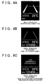
- FIGS. 9A to 9B are views of screens on the display portion in the second embodiment, and
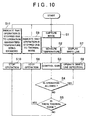
- FIG. 10 is a flowchart illustrating the operation of the white line detection apparatus according to the second embodiment.
- the components in this second embodiment that are the same those in the first embodiment will be denoted by the same reference characters and descriptions of those components will be omitted.
- the white line detection apparatus 20 includes an imaging portion 3, a gain controlling portion 4, a white line detection portion 5, a temperature measuring portion 6, a determining portion 15, an operation controlling portion 8, a brightness measuring portion 13, and a display portion 21.
- the display portion 21 of the second embodiment differs from that of the first embodiment. All of the other components are the same as those of the first embodiment.
- the display portion 21 informs the user of the operating state of the white line detection portion 5.
- the display portion 21 indicates whether the white line detection portion 5 is in an operational state (i.e., in which the amplifier is operating), a non-recognizing state due to excessive thermal noise, or a non-recognizing state due to the temperature of the imaging portion 3 exceeding the operation guaranteed temperature, based on the determination results from the determining portion 15. That is, if the determination portion 15 determines that operation is allowed based on fact that the coordinates on the operation control map 9 which are determined by the gain and the temperature are in the allowed region 10 such that the white line detection portion 5 is in the recognizing state, the display portion 21 displays the white line detected by the white line detection portion 5.
- the display portion 21 indicates that the white line detection portion 5 is in the non-recognizing state due to the excessive thermal noise. If the determination portion 15 determines that operation is not allowed based on the fact that the coordinates on the operation control map 9 which are determined by the gain and the temperature are in the second disallowed region 111 such that the white line detection portion 5 is in the non-recognizing state, the display portion 21 indicates that the white line detection portion 5 is in the non-recognizing state due to the temperature of the imaging portion 3 exceeding the operation guaranteed temperature.
- FIG 9A is a view of an example of a screen displayed by the display portion 21 when the white line detection portion 5 is in the operational state.
- two thick white lines detected by the white line detection portion 5 appear on the screen.
- the outside air temperature and the total distance travelled may also be displayed at the bottom of the screen. This screen indicates that the white line detection portion 5 is operating normally.
- FIG 9B is a view of an example of a screen displayed by the display portion 21 when the white line detection portion 5 is in the non-recognizing state due to the influence of excessive amplified thermal noise.
- two thin vertical white lines are shown. These white lines indicate that the white line detection portion 5 is unable to detect a white line due to excessive amplified thermal noise.
- the outside air temperature and the total distance travelled may be displayed at the bottom of the screen.
- FIG. 9C is a view of an example of a screen displayed by the display portion 21 when the white line detection portion 5 is in the non-recognizing state as a result of the temperature of the imaging portion 3 exceeding the operation guaranteed temperature.
- the phrase "LKA CURRENLY UNAVAILABLE" appears in the center of the screen. This phrase indicates that the white line detection portion 5 is unable to recognize a white line because the temperature of the imaging portion 3 exceeds the operation guaranteed temperature.
- the outside air temperature and the total distance travelled may be displayed at the bottom of the screen.
- FIG 10 is a flowchart illustrating an example of the operation of the white line detection apparatus 20.
- the imaging portion 3 captures an image of the road surface ahead of the vehicle (step S1).
- the temperature measuring portion 6 measures the temperature of the imaging portion 3 (step S2).
- the gain controlling portion 4 controls the gain of the amplifying portion based on the brightness around the vehicle (step S3).
- the determining portion 15 determines whether operation of the white line detection portion 5 is to be permitted based on whether the coordinates on the operation control map 9 which are determined by the gain and the temperature are in the allowed region 10, the first disallowed region 110, or the second disallowed region 111 (steps S4, S5).
- step S6 the white line detection portion 5 detects the white line based on the captured image signal. Then the display portion 21 displays the white line detected by the white line detection portion 5 (step S7).
- the determining portion 15 makes a determination to prohibit operation of the white line detection portion 5 due to excessive amplified thermal noise and the process proceeds on to step S8. If the white line detection portion 5 is already operating, operation of the white line detection portion 5 is stopped in step S8. If the white line detection portion 5 is not yet operating, the white line detection portion 5 is maintained in the inoperative state in step S8. Next, the display portion 21 indicates that the white line detection portion 5 is not operating (i.e., is stopped) (step S9) due to excessive amplified thermal noise.
- the determining portion 15 makes a determination to prohibit operation of the white line detection portion 5 and the process proceeds on to step S10. If the white line detection portion 5 is already operating, operation of the white line detection portion 5 is stopped in step S10. If the white line detection portion 5 is not yet operating, the white line detection portion 5 is maintained in the inoperative state in step S10. Next, the display portion 21 indicates that the white line detection portion 5 is in the inoperative state (step S 11) due to the temperature of the imaging portion 3 exceeding the operation guaranteed temperature.
- the operation of the white line detection apparatus 20 is as described above.
- the white line detection apparatus 20 enables the white line detection portion 5 to function sufficiently in the range where the influence from thermal noise is acceptable. Also, in the foregoing comparative example, the state in which the white line detection portion 5 has stopped operating due to thermal noise is indicated on the screen in the same manner that the state in which the white line detection portion 5 has stopped operating due to the temperature of the imaging portion 3 exceeding the operation guaranteed temperature (see FIG. 3B ). As a result, the user may not know why the white line detection portion 5 has stopped operating and suspect that the white line detection apparatus 20 is faulty.
- the white line detection portion 5 when operation of the white line detection portion 5 stops due to thermal noise, it is treated just as non-recognizing state and is indicated by a screen different from the screen that appears when the white line detection portion 5 stops operating due to the temperature of the imaging portion 3 exceeding the operation guaranteed temperature. Accordingly, the user will not suspect that the white line detection apparatus 20 is faulty.
- the invention is useful when applied to a vehicle detecting white line in an area where low and high temperatures are drastically different from one another and the brightness around the vehicle changes frequently.
Landscapes
- Engineering & Computer Science (AREA)
- Multimedia (AREA)
- Signal Processing (AREA)
- Automation & Control Theory (AREA)
- General Physics & Mathematics (AREA)
- Transportation (AREA)
- Mechanical Engineering (AREA)
- Physics & Mathematics (AREA)
- Human Computer Interaction (AREA)
- Theoretical Computer Science (AREA)
- Traffic Control Systems (AREA)
- Closed-Circuit Television Systems (AREA)
- Studio Devices (AREA)
- Image Processing (AREA)
- Image Analysis (AREA)
- Road Signs Or Road Markings (AREA)
Claims (7)
- Computerprogrammprodukt zum Veranlassen einer Weißlinie-Erfassungsvorrichtung (1), um unter Verwendung eines Betriebssteuerkennfelds (9; 18) zu arbeiten, welches anwendbar ist, um als eine Bestimmungsreferenz zum dahingehenden Bestimmen in Bezug genommen zu werden, ob ein Betrieb eines Weißlinie-Erfassungsabschnitts (5) der Weißlinie-Erfassungsvorrichtung (1) zuzulassen ist, die versehen ist mit einem Fahrbahnoberfläche-Bildgebungsabschnitt (3), der einen Festkörper-Bildgebungssensor umfasst, dem Weißlinie-Erfassungsabschnitt (5), der zum Erfassen einer weißen Linie auf einer Fahrbahn basierend auf einem aufgenommenen Bild der Fahrbahnoberfläche angepasst ist, und einen Bestimmungsabschnitt (15), der zum Bestimmen angepasst ist, ob ein Betrieb des Weißlinie-Erfassungsabschnitts (5) zuzulassen ist,
dadurch gekennzeichnet, dass das Betriebssteuerkennfeld aufweist:einen zulässigen Bereich (10), in dem ein Betrieb des Weißlinie-Erfassungsabschnitts (5) zugelassen ist, welcher basierend auf den Werten des Gewinns eines durch den Fahrbahnoberfläche-Bildgebungsabschnitt (3) erzeugten Fahrbahnoberfläche-Bildsignals und einer erfassten Temperatur des Fahrbahnoberfläche-Bildgebungsabschnitts (3) festgelegt ist, welche Variable in dem Betriebssteuerkennfeld (9; 18) darstellen;einen ersten unzulässigen Bereich (11), in dem ein Betrieb des Weißlinie-Erfassungsabschnitts (5) nicht zugelassen ist, welcher auch basierend auf den Werten der Variablen festgelegt ist; undeinen zweiten unzulässigen Bereich (11), in dem ein Betrieb des Weißlinie-Erfassungsabschnitts (5) nicht zugelassen ist, welcher für die Temperatur des Bildgebungsabschnitts festgelegt ist, die eine Temperatur überschreitet, auf der ein Betrieb des Bildgebungsabschnitts gewährleistet ist,einen Pufferbereich (19), der zwischen dem zulässigen Bereich (10) und dem ersten unzulässigen Bereich (11) eingeschoben ist,wobei der zulässige Bereich (10) ein Bereich ist, der eingestellt wird, wenn eine verringerte Genauigkeit einer Erfassung einer weißen Linie infolge des thermischen Rauschens, das in dem Festkörper-Bildgebungssensor erzeugt wird, in einen akzeptablen Wertebereich fällt, und der erste zulässige Bereich (11) ein Bereich ist, der eingestellt wird, wenn die verringerte Genauigkeit einer Erfassung einer weißen Linie aus dem akzeptablen Wertebereich heraus fällt, undwobei der Pufferbereich (19) angepasst ist, wie der erste unzulässige Bereich (11) zu fungieren, falls durch den Gewinn und die Temperatur bestimmte Koordinaten infolge einer Änderung des Gewinns ausgehend von dem ersten unzulässigen Bereich (11) in den Pufferbereich (19) eintreten, und der Pufferbereich (19) angepasst ist, wie der zulässige Bereich (10) zu fungieren, falls die Koordinaten infolge einer Änderung des Gewinns ausgehend von dem zulässigen Bereich (10) in den Pufferbereich (19) eintreten. - Weißlinie-Erfassungsvorrichtung (1), die zum Erfassen einer weißen Linie auf einer Fahrbahn angepasst ist, mit:einem Fahrbahnoberfläche-Bildgebungsabschnitt (3), der einen Festkörper-Bildgebungssensor umfasst, der zum Aufnehmen eines Bildes der Fahrbahnoberfläche angepasst ist;einem Gewinnsteuerabschnitt (4), der zum Steuern des Gewinns beim Verstärken eines durch den Fahrbahnoberfläche-Bildgebungsabschnitt (3) erzeugten Fahrbahnoberfläche-Bildsignals basierend auf der Helligkeit rund um ein Fahrzeug angepasst ist;einem Weißlinie-Erfassungsabschnitt (5), der zum Vergleichen der Differenz zwischen Helligkeitswerten der Fahrbahn und einer weißen Linie in dem verstärkten Fahrbahnoberfläche-Bildsignal mit einem Schwellenwert, sowie zum Erfassen der weißen Linie basierend auf den Vergleichsergebnissen angepasst ist;einem Temperaturmessabschnitt (6), der zum Messen der Temperatur des Fahrbahnoberfläche-Bildgebungsabschnitts (3) angepasst ist;einem Bestimmungsabschnitt (7), der zum Bestimmen, ob ein Betrieb des Weißlinie-Erfassungsabschnitts (5) zuzulassen ist, basierend auf dem durch den Gewinnsteuerabschnitt (4) gesteuerten Gewinn und der durch den Temperaturmessabschnitt (6) gemessenen Temperatur angepasst ist; undeinem Betriebssteuerabschnitt (8), der zum Steuern des Betriebs des Weißlinie-Erfassungsabschnitts (5) basierend auf den Bestimmungsergebnissen des Bestimmungsabschnitts (7) angepasst ist,dadurch gekennzeichnet, dass der Bestimmungsabschnitt (7) ein Betriebssteuerkennfeld (9; 18) umfasst, in dem der Gewinn und die Temperatur Variable darstellen und das aufweist: einen zulässigen Bereich (10), in dem ein Betrieb des Weißlinie-Erfassungsabschnitts (5) zugelassen ist, und einen ersten unzulässigen Bereich (11), in dem ein Betrieb des Weißlinie-Erfassungsabschnitts (5) nicht zugelassen ist, wobei diese basierend auf den Werten der Variablen festgelegt sind, und einen zweiten unzulässigen Bereich (11), in dem ein Betrieb des Weißlinie-Erfassungsabschnitts (5) nicht zugelassen ist, wobei dieser für die Temperatur des Bildgebungsabschnitts festgelegt, die eine Temperatur überschreitet, auf der ein Betrieb des Bildgebungsabschnitts gewährleistet ist, wobei ein Pufferbereich (19) zwischen dem zulässigen Bereich (10) und dem ersten unzulässigen Bereich (11) eingeschoben ist, und wobei der Bestimmungsabschnitt (7) angepasst ist, basierend auf dem Betriebssteuerkennfeld (9; 18) zu bestimmen, ob der Betrieb zuzulassen ist, undwobei der zulässige Bereich (10) ein Bereich ist, der eingestellt wird, wenn eine verringerte Genauigkeit einer Erfassung einer weißen Linie infolge des thermischen Rauschens, das in dem Festkörper-Bildgebungssensor erzeugt wird, in einen akzeptablen Wertebereich fällt, und der erste zulässige Bereich (11) ein Bereich ist, der eingestellt wird, wenn die verringerte Genauigkeit einer Erfassung einer weißen Linie aus dem akzeptablen Wertebereich heraus fällt, undwobei der Pufferbereich (19) angepasst ist, wie der erste unzulässige Bereich (11) zu fungieren, falls durch den Gewinn und die Temperatur bestimmte Koordinaten infolge einer Änderung des Gewinns ausgehend von dem ersten unzulässigen Bereich (11) in den Pufferbereich (19) eintreten, und der Pufferbereich (19) angepasst ist, wie der zulässige Bereich (10) zu fungieren, falls die Koordinaten infolge einer Änderung des Gewinns ausgehend von dem zulässigen Bereich (10) in den Pufferbereich (19) eintreten.
- Weißlinie-Erfassungsvorrichtung gemäß Anspruch 2, zusätzlich mit:einem Anzeigeabschnitt (12), der zum Informieren eines Benutzers über den Betriebszustand des Weißlinie-Erfassungsabschnitts (5) angepasst ist,wobei der Anzeigeabschnitt (12) angepasst ist, um anzugeben, dass der Weißlinie-Erfassungsabschnitt i) arbeitet oder ii) nicht arbeitet.
- Weißlinie-Erfassungsvorrichtung gemäß Anspruch 2, zusätzlich mit:einem Anzeigeabschnitt (21), der zum Informieren eines Benutzers über den Betriebszustand des Weißlinie-Erfassungsabschnitts (5) angepasst ist,wobei das Betriebssteuerkennfeld (18) zusätzlich einen Bereich, wo die Temperatur eine einen Betrieb gewährleistende Temperatur der Weißlinie-Erfassungsvorrichtung überschreitet, als einen betriebsunzulässigen Bereich (111) umfasst, und der Anzeigeabschnitt (21) angibt, dass der Weißlinie-Erfassungsabschnitt (5) i) arbeitet, ii) infolge thermischen Rauschens nicht arbeitet, oder iii) infolge dessen nicht arbeitet, dass die einen Betrieb gewährleistende Temperatur überschritten ist.
- Anzeigeabschnitt (12; 21) einer Weißlinie-Erfassungsvorrichtung (1), der zum Informieren eines Benutzers über den Betriebszustand eines Weißlinie-Erfassungsabschnitts der Weißlinie-Erfassungsvorrichtung angepasst ist,
wobei die Weißlinie-Erfassungsvorrichtung versehen ist mit einem Fahrbahnoberfläche-Bildgebungsabschnitt (3), der einen Festkörper-Bildgebungssensor umfasst, dem Weißlinie-Erfassungsabschnitt (5), der zum Erfassen einer weißen Linie auf einer Fahrbahn basierend auf einem aufgenommenen Bild der Fahrbahnoberfläche angepasst ist, einen Bestimmungsabschnitt (15), der zum Bestimmen, ob ein Betrieb des Weißlinie-Erfassungsabschnitts (5) zuzulassen ist, basierend auf einem Betriebssteuerkennfeld (9; 18) angepasst ist, in dem die Temperatur des Fahrbahnoberfläche-Bildgebungsabschnitts (3) und der Gewinn beim Verstärken eines durch den Fahrbahnoberfläche-Bildgebungsabschnitt (3) erzeugten Fahrbahnoberfläche-Bildsignals Variable sind, und einen Betriebssteuerabschnitt (8), der zum Steuern des Betriebs des Weißlinie-Erfassungsabschnitts (5) basierend auf den Bestimmungsergebnissen des Bestimmungsabschnitts (15) angepasst ist, und
dadurch gekennzeichnet, dass das Betriebssteuerkennfeld aufweist:einen zulässigen Bereich (10), in dem ein Betrieb des Weißlinie-Erfassungsabschnitts (5) zugelassen ist, und einen ersten unzulässigen Bereich (11), in dem ein Betrieb des Weißlinie-Erfassungsabschnitts (5) nicht zugelassen ist, wobei diese basierend auf den Werten der Variablen festgelegt sind, und einen zweiten unzulässigen Bereich (11), in dem ein Betrieb des Weißlinie-Erfassungsabschnitts (5) nicht zugelassen ist, wobei dieser für die Temperatur des Bildgebungsabschnitts festgelegt ist, die eine Temperatur überschreitet, auf der ein Betrieb des Bildgebungsabschnitts gewährleistet ist, und einen Pufferbereich (19), der zwischen dem zulässigen Bereich (10) und dem ersten unzulässigen Bereich (11) eingeschoben ist, wobei der zulässige Bereich (10) ein Bereich ist, der eingestellt wird, wenn eine verringerte Genauigkeit einer Erfassung einer weißen Linie infolge des thermischen Rauschens, das in dem Festkörper-Bildgebungssensor erzeugt wird, in einen akzeptablen Wertebereich fällt fällt, und der erste unzulässige Bereich (11) ein Bereich ist, der eingestellt wird, wenn die verringerte Genauigkeit eine Erfassung einer weißen Linie aus dem akzeptablen Wertebereich heraus fällt, und wobei der Pufferbereich (19) angepasst ist, wie der erste unzulässige Bereich (11) zu fungieren, falls durch den Gewinn und die Temperatur bestimmte Koordinaten infolge einer Änderung des Gewinns ausgehend von dem ersten unzulässigen Bereich (11) in den Pufferbereich (19) eintreten, und der Pufferbereich (19) angepasst ist, wie der zulässige Bereich (10) zu fungieren, falls die Koordinaten infolge einer Änderung des Gewinns ausgehend von dem zulässigen Bereich (10) in den Pufferbereich (19) eintreten, undder Anzeigeabschnitt angepasst ist, um anzugeben, dass der Weißlinie-Erfassungsabschnitt (5) i) arbeitet, wenn Koordinaten der Variablen in den zulässigen Bereich des Betriebssteuerkennfelds fallen, ii) gesteuert ist, um infolge eines thermischen Rauschens, das in dem Fahrbahnoberfläche-Bildgebungsabschnitt (3) erzeugt wird, nicht zu arbeiten, wenn Koordinaten der Variablen in den ersten unzulässigen Bereich des Betriebssteuerkennfelds fallen, oder iii) gesteuert ist, um infolge dessen nicht zu arbeiten, dass eine einen Betrieb gewährleistende Temperatur der Weißlinie-Erfassungsvorrichtung überschritten ist, wenn Koordinaten der Variablen in den zweiten unzulässigen Bereich des Betriebssteuerkennfelds fallen. - Anzeigeabschnitt gemäß Anspruch 5, wobei in einem Fall, dass der Weißlinie-Erfassungsabschnitt (5) arbeitet, der Anzeigeabschnitt angepasst ist, eine durch den Weißlinie-Erfassungsabschnitt (5) erfasste weiße Linie unter Verwendung einer weißen Linie anzuzeigen, die dicker ist als in einem Fall, dass der Weißlinie-Erfassungsabschnitt (5) gesteuert ist, um infolge eines thermischen Rauschens, das in dem Fahrbahnoberfläche-Bildgebungsabschnitt (3) erzeugt wird, nicht zu arbeiten.
- Anzeigeabschnitt gemäß Anspruch 5 oder 6, wobei, falls der Weißlinie-Erfassungsabschnitt (5) gesteuert ist, um infolge dessen nicht zu arbeiten, dass eine einen Betrieb gewährleistende Temperatur der Weißlinie-Erfassungsvorrichtung überschritten ist, der Anzeigeabschnitt angepasst ist, um anzugeben, dass ein Fahrspurhalteassistenzsystem gerade nicht zur Verfügung steht.
Applications Claiming Priority (2)
| Application Number | Priority Date | Filing Date | Title |
|---|---|---|---|
| JP2008020789A JP4708443B2 (ja) | 2008-01-31 | 2008-01-31 | 作動制御マップおよび白線認識装置 |
| PCT/IB2009/000125 WO2009095759A2 (en) | 2008-01-31 | 2009-01-26 | Operation control map, display unit, and white line detection apparatus |
Publications (2)
| Publication Number | Publication Date |
|---|---|
| EP2248070A2 EP2248070A2 (de) | 2010-11-10 |
| EP2248070B1 true EP2248070B1 (de) | 2012-05-23 |
Family
ID=40911978
Family Applications (1)
| Application Number | Title | Priority Date | Filing Date |
|---|---|---|---|
| EP09706705A Not-in-force EP2248070B1 (de) | 2008-01-31 | 2009-01-26 | Operationssteuerabbildung, anzeigeeinheit und weissliniendetektionsvorrichtung |
Country Status (4)
| Country | Link |
|---|---|
| US (1) | US8433096B2 (de) |
| EP (1) | EP2248070B1 (de) |
| JP (1) | JP4708443B2 (de) |
| WO (1) | WO2009095759A2 (de) |
Families Citing this family (9)
| Publication number | Priority date | Publication date | Assignee | Title |
|---|---|---|---|---|
| JP4849346B2 (ja) * | 2008-09-08 | 2012-01-11 | トヨタ自動車株式会社 | 路面区画マーク認識装置および車線逸脱防止装置 |
| JP6328369B2 (ja) * | 2012-11-27 | 2018-05-23 | クラリオン株式会社 | 車載用制御装置 |
| JP6003746B2 (ja) | 2013-03-22 | 2016-10-05 | 株式会社デンソー | 車両制御装置 |
| US20150277700A1 (en) * | 2013-04-12 | 2015-10-01 | Usens, Inc. | System and method for providing graphical user interface |
| DE102014106034B4 (de) * | 2014-04-30 | 2022-02-10 | Connaught Electronics Ltd. | Verfahren zum Versetzen eines Bildsensors einer Fahrzeugkamera eines Kraftfahrzeugs in einen Bildaufnahmezustand, Kamerasystem sowie Kraftfahrzeug |
| IL287136B2 (en) | 2016-02-05 | 2023-09-01 | Denali Therapeutics Inc | Receptor inhibitors - interacting with protein kinase 1 |
| DE102017208663B4 (de) * | 2016-06-09 | 2024-12-05 | Conti Temic Microelectronic Gmbh | Umgebungserfassende Vorrichtung sowie Kraftfahrzeug mit einer solchen umgebungserfassenden Vorrichtung |
| JP7208137B2 (ja) | 2016-12-09 | 2023-01-18 | デナリ セラピューティクス インコーポレイテッド | 化合物、組成物および方法 |
| TW202334164A (zh) | 2022-01-12 | 2023-09-01 | 美商戴納立製藥公司 | (S)-5-苄基-N-(5-甲基-4-側氧基-2,3,4,5-四氫吡啶並[3,2-b][1,4]氧氮呯-3-基)-4H-1,2,4-三唑-3-甲醯胺的晶型 |
Family Cites Families (17)
| Publication number | Priority date | Publication date | Assignee | Title |
|---|---|---|---|---|
| JPH02131084A (ja) | 1988-11-10 | 1990-05-18 | Nec Corp | テレビカメラ |
| JPH0837612A (ja) * | 1994-07-22 | 1996-02-06 | Canon Inc | 撮像装置 |
| JP3462812B2 (ja) * | 1999-09-22 | 2003-11-05 | 富士重工業株式会社 | 車載カメラの電源制御方法ならびに装置 |
| JP2001213240A (ja) * | 2000-02-04 | 2001-08-07 | Hitachi Ltd | 車載用カメラ装置 |
| JP3732115B2 (ja) * | 2001-05-23 | 2006-01-05 | 三菱電機株式会社 | 画像処理装置 |
| JP2003032435A (ja) | 2001-07-18 | 2003-01-31 | Canon Inc | 画像認識装置 |
| JP3780922B2 (ja) * | 2001-11-30 | 2006-05-31 | 日産自動車株式会社 | 道路白線認識装置 |
| JP3934506B2 (ja) * | 2002-08-06 | 2007-06-20 | オリンパス株式会社 | 撮像システムおよび画像処理プログラム |
| JP4314979B2 (ja) * | 2003-11-25 | 2009-08-19 | 株式会社デンソー | 白線検出装置 |
| JP2005175961A (ja) | 2003-12-11 | 2005-06-30 | Canon Inc | 撮像装置、撮像感度制御方法、シャッタ制御方法、及びプログラム |
| JP2005215985A (ja) * | 2004-01-29 | 2005-08-11 | Fujitsu Ltd | 走行車線判定プログラムおよびその記録媒体、走行車線判定装置ならびに走行車線判定方法 |
| JP4093208B2 (ja) * | 2004-05-28 | 2008-06-04 | トヨタ自動車株式会社 | 車両用走路判定装置 |
| JP4599894B2 (ja) * | 2004-06-01 | 2010-12-15 | トヨタ自動車株式会社 | 車線逸脱警報装置 |
| JP4242334B2 (ja) * | 2004-11-30 | 2009-03-25 | 本田技研工業株式会社 | 車両周辺監視装置 |
| JP4754284B2 (ja) * | 2005-07-05 | 2011-08-24 | 富士重工業株式会社 | 車載機器の防熱構造 |
| JP4899599B2 (ja) * | 2006-04-07 | 2012-03-21 | マツダ株式会社 | 車両の障害物検知装置 |
| JP4849346B2 (ja) | 2008-09-08 | 2012-01-11 | トヨタ自動車株式会社 | 路面区画マーク認識装置および車線逸脱防止装置 |
-
2008
- 2008-01-31 JP JP2008020789A patent/JP4708443B2/ja active Active
-
2009
- 2009-01-26 US US12/865,824 patent/US8433096B2/en not_active Expired - Fee Related
- 2009-01-26 WO PCT/IB2009/000125 patent/WO2009095759A2/en not_active Ceased
- 2009-01-26 EP EP09706705A patent/EP2248070B1/de not_active Not-in-force
Also Published As
| Publication number | Publication date |
|---|---|
| JP4708443B2 (ja) | 2011-06-22 |
| WO2009095759A2 (en) | 2009-08-06 |
| US20110001640A1 (en) | 2011-01-06 |
| EP2248070A2 (de) | 2010-11-10 |
| WO2009095759A3 (en) | 2009-10-08 |
| JP2009181411A (ja) | 2009-08-13 |
| US8433096B2 (en) | 2013-04-30 |
Similar Documents
| Publication | Publication Date | Title |
|---|---|---|
| EP2248070B1 (de) | Operationssteuerabbildung, anzeigeeinheit und weissliniendetektionsvorrichtung | |
| JP5375814B2 (ja) | 露出制御装置 | |
| EP2927060A1 (de) | Bildverarbeitungsvorrichtung für ein fahrzeug | |
| US8115809B2 (en) | Vehicle surroundings monitoring apparatus | |
| US20110205363A1 (en) | Boundary line detection system with improved detection-performance | |
| US9807320B2 (en) | Operation input device, operation input method, and computer-readable recording medium | |
| US20100039551A1 (en) | Digital image capture device and exposure method thereof | |
| US11917308B2 (en) | Imaging device, image recording device, and imaging method for capturing a predetermined event | |
| JP4757932B2 (ja) | 車両用撮像装置の露出制御装置及び露出制御方法 | |
| US8373754B2 (en) | Method and system for evaluating brightness values in sensor images of image-evaluating adaptive cruise control systems | |
| EP1233612B1 (de) | CMOS Bildsensor mit erweitertem Dynamikbereich | |
| JP5246254B2 (ja) | 車載カメラの露出制御値の決定方法 | |
| JP2019061303A (ja) | 車両の周辺監視装置と周辺監視方法 | |
| JP4247547B2 (ja) | カメラ用露光量制御方法および装置 | |
| JP4661934B2 (ja) | 画像処理装置 | |
| US10783619B2 (en) | Image generating apparatus for combining plural images based on different shutter times | |
| JP2005033680A (ja) | 車両用画像処理装置 | |
| JP2001177768A5 (de) | ||
| JP2009294974A (ja) | 画像処理による侵入者検知装置 | |
| JP4317036B2 (ja) | カメラ用汚れ検出装置、カメラ用汚れ検出方法 | |
| JP2003110935A (ja) | Ccdカメラ | |
| EP3051384B1 (de) | Infrarotbasierte gestenerkennung | |
| JP4179246B2 (ja) | 撮像装置 | |
| JP2002354463A (ja) | 画像処理装置 | |
| KR20090126702A (ko) | 카메라 영상의 블루밍 제거장치 및 방법 |
Legal Events
| Date | Code | Title | Description |
|---|---|---|---|
| PUAI | Public reference made under article 153(3) epc to a published international application that has entered the european phase |
Free format text: ORIGINAL CODE: 0009012 |
|
| 17P | Request for examination filed |
Effective date: 20100830 |
|
| AK | Designated contracting states |
Kind code of ref document: A2 Designated state(s): AT BE BG CH CY CZ DE DK EE ES FI FR GB GR HR HU IE IS IT LI LT LU LV MC MK MT NL NO PL PT RO SE SI SK TR |
|
| AX | Request for extension of the european patent |
Extension state: AL BA RS |
|
| 17Q | First examination report despatched |
Effective date: 20110228 |
|
| DAX | Request for extension of the european patent (deleted) | ||
| GRAP | Despatch of communication of intention to grant a patent |
Free format text: ORIGINAL CODE: EPIDOSNIGR1 |
|
| GRAS | Grant fee paid |
Free format text: ORIGINAL CODE: EPIDOSNIGR3 |
|
| RAP1 | Party data changed (applicant data changed or rights of an application transferred) |
Owner name: TOYOTA JIDOSHA KABUSHIKI KAISHA Owner name: DENSO CORPORATION |
|
| GRAA | (expected) grant |
Free format text: ORIGINAL CODE: 0009210 |
|
| AK | Designated contracting states |
Kind code of ref document: B1 Designated state(s): AT BE BG CH CY CZ DE DK EE ES FI FR GB GR HR HU IE IS IT LI LT LU LV MC MK MT NL NO PL PT RO SE SI SK TR |
|
| REG | Reference to a national code |
Ref country code: GB Ref legal event code: FG4D |
|
| REG | Reference to a national code |
Ref country code: CH Ref legal event code: EP |
|
| REG | Reference to a national code |
Ref country code: AT Ref legal event code: REF Ref document number: 559365 Country of ref document: AT Kind code of ref document: T Effective date: 20120615 |
|
| REG | Reference to a national code |
Ref country code: IE Ref legal event code: FG4D |
|
| REG | Reference to a national code |
Ref country code: DE Ref legal event code: R096 Ref document number: 602009007210 Country of ref document: DE Effective date: 20120719 |
|
| REG | Reference to a national code |
Ref country code: NL Ref legal event code: VDEP Effective date: 20120523 |
|
| REG | Reference to a national code |
Ref country code: LT Ref legal event code: MG4D Effective date: 20120523 |
|
| PG25 | Lapsed in a contracting state [announced via postgrant information from national office to epo] |
Ref country code: SE Free format text: LAPSE BECAUSE OF FAILURE TO SUBMIT A TRANSLATION OF THE DESCRIPTION OR TO PAY THE FEE WITHIN THE PRESCRIBED TIME-LIMIT Effective date: 20120523 Ref country code: NO Free format text: LAPSE BECAUSE OF FAILURE TO SUBMIT A TRANSLATION OF THE DESCRIPTION OR TO PAY THE FEE WITHIN THE PRESCRIBED TIME-LIMIT Effective date: 20120823 Ref country code: LT Free format text: LAPSE BECAUSE OF FAILURE TO SUBMIT A TRANSLATION OF THE DESCRIPTION OR TO PAY THE FEE WITHIN THE PRESCRIBED TIME-LIMIT Effective date: 20120523 Ref country code: FI Free format text: LAPSE BECAUSE OF FAILURE TO SUBMIT A TRANSLATION OF THE DESCRIPTION OR TO PAY THE FEE WITHIN THE PRESCRIBED TIME-LIMIT Effective date: 20120523 Ref country code: CY Free format text: LAPSE BECAUSE OF FAILURE TO SUBMIT A TRANSLATION OF THE DESCRIPTION OR TO PAY THE FEE WITHIN THE PRESCRIBED TIME-LIMIT Effective date: 20120523 Ref country code: IS Free format text: LAPSE BECAUSE OF FAILURE TO SUBMIT A TRANSLATION OF THE DESCRIPTION OR TO PAY THE FEE WITHIN THE PRESCRIBED TIME-LIMIT Effective date: 20120923 |
|
| REG | Reference to a national code |
Ref country code: AT Ref legal event code: MK05 Ref document number: 559365 Country of ref document: AT Kind code of ref document: T Effective date: 20120523 |
|
| PG25 | Lapsed in a contracting state [announced via postgrant information from national office to epo] |
Ref country code: PT Free format text: LAPSE BECAUSE OF FAILURE TO SUBMIT A TRANSLATION OF THE DESCRIPTION OR TO PAY THE FEE WITHIN THE PRESCRIBED TIME-LIMIT Effective date: 20120924 Ref country code: GR Free format text: LAPSE BECAUSE OF FAILURE TO SUBMIT A TRANSLATION OF THE DESCRIPTION OR TO PAY THE FEE WITHIN THE PRESCRIBED TIME-LIMIT Effective date: 20120824 Ref country code: LV Free format text: LAPSE BECAUSE OF FAILURE TO SUBMIT A TRANSLATION OF THE DESCRIPTION OR TO PAY THE FEE WITHIN THE PRESCRIBED TIME-LIMIT Effective date: 20120523 Ref country code: SI Free format text: LAPSE BECAUSE OF FAILURE TO SUBMIT A TRANSLATION OF THE DESCRIPTION OR TO PAY THE FEE WITHIN THE PRESCRIBED TIME-LIMIT Effective date: 20120523 Ref country code: HR Free format text: LAPSE BECAUSE OF FAILURE TO SUBMIT A TRANSLATION OF THE DESCRIPTION OR TO PAY THE FEE WITHIN THE PRESCRIBED TIME-LIMIT Effective date: 20120523 |
|
| PG25 | Lapsed in a contracting state [announced via postgrant information from national office to epo] |
Ref country code: BE Free format text: LAPSE BECAUSE OF FAILURE TO SUBMIT A TRANSLATION OF THE DESCRIPTION OR TO PAY THE FEE WITHIN THE PRESCRIBED TIME-LIMIT Effective date: 20120523 |
|
| PG25 | Lapsed in a contracting state [announced via postgrant information from national office to epo] |
Ref country code: NL Free format text: LAPSE BECAUSE OF FAILURE TO SUBMIT A TRANSLATION OF THE DESCRIPTION OR TO PAY THE FEE WITHIN THE PRESCRIBED TIME-LIMIT Effective date: 20120523 Ref country code: RO Free format text: LAPSE BECAUSE OF FAILURE TO SUBMIT A TRANSLATION OF THE DESCRIPTION OR TO PAY THE FEE WITHIN THE PRESCRIBED TIME-LIMIT Effective date: 20120523 Ref country code: EE Free format text: LAPSE BECAUSE OF FAILURE TO SUBMIT A TRANSLATION OF THE DESCRIPTION OR TO PAY THE FEE WITHIN THE PRESCRIBED TIME-LIMIT Effective date: 20120523 Ref country code: SK Free format text: LAPSE BECAUSE OF FAILURE TO SUBMIT A TRANSLATION OF THE DESCRIPTION OR TO PAY THE FEE WITHIN THE PRESCRIBED TIME-LIMIT Effective date: 20120523 Ref country code: CZ Free format text: LAPSE BECAUSE OF FAILURE TO SUBMIT A TRANSLATION OF THE DESCRIPTION OR TO PAY THE FEE WITHIN THE PRESCRIBED TIME-LIMIT Effective date: 20120523 Ref country code: DK Free format text: LAPSE BECAUSE OF FAILURE TO SUBMIT A TRANSLATION OF THE DESCRIPTION OR TO PAY THE FEE WITHIN THE PRESCRIBED TIME-LIMIT Effective date: 20120523 Ref country code: AT Free format text: LAPSE BECAUSE OF FAILURE TO SUBMIT A TRANSLATION OF THE DESCRIPTION OR TO PAY THE FEE WITHIN THE PRESCRIBED TIME-LIMIT Effective date: 20120523 |
|
| RAP2 | Party data changed (patent owner data changed or rights of a patent transferred) |
Owner name: TOYOTA JIDOSHA KABUSHIKI KAISHA Owner name: DENSO CORPORATION |
|
| PG25 | Lapsed in a contracting state [announced via postgrant information from national office to epo] |
Ref country code: IT Free format text: LAPSE BECAUSE OF FAILURE TO SUBMIT A TRANSLATION OF THE DESCRIPTION OR TO PAY THE FEE WITHIN THE PRESCRIBED TIME-LIMIT Effective date: 20120523 Ref country code: PL Free format text: LAPSE BECAUSE OF FAILURE TO SUBMIT A TRANSLATION OF THE DESCRIPTION OR TO PAY THE FEE WITHIN THE PRESCRIBED TIME-LIMIT Effective date: 20120523 |
|
| PLBE | No opposition filed within time limit |
Free format text: ORIGINAL CODE: 0009261 |
|
| STAA | Information on the status of an ep patent application or granted ep patent |
Free format text: STATUS: NO OPPOSITION FILED WITHIN TIME LIMIT |
|
| PG25 | Lapsed in a contracting state [announced via postgrant information from national office to epo] |
Ref country code: ES Free format text: LAPSE BECAUSE OF FAILURE TO SUBMIT A TRANSLATION OF THE DESCRIPTION OR TO PAY THE FEE WITHIN THE PRESCRIBED TIME-LIMIT Effective date: 20120903 |
|
| 26N | No opposition filed |
Effective date: 20130226 |
|
| REG | Reference to a national code |
Ref country code: DE Ref legal event code: R097 Ref document number: 602009007210 Country of ref document: DE Effective date: 20130226 |
|
| PG25 | Lapsed in a contracting state [announced via postgrant information from national office to epo] |
Ref country code: BG Free format text: LAPSE BECAUSE OF FAILURE TO SUBMIT A TRANSLATION OF THE DESCRIPTION OR TO PAY THE FEE WITHIN THE PRESCRIBED TIME-LIMIT Effective date: 20120823 |
|
| PG25 | Lapsed in a contracting state [announced via postgrant information from national office to epo] |
Ref country code: MC Free format text: LAPSE BECAUSE OF NON-PAYMENT OF DUE FEES Effective date: 20130131 |
|
| REG | Reference to a national code |
Ref country code: CH Ref legal event code: PL |
|
| GBPC | Gb: european patent ceased through non-payment of renewal fee |
Effective date: 20130126 |
|
| REG | Reference to a national code |
Ref country code: IE Ref legal event code: MM4A |
|
| PG25 | Lapsed in a contracting state [announced via postgrant information from national office to epo] |
Ref country code: LI Free format text: LAPSE BECAUSE OF NON-PAYMENT OF DUE FEES Effective date: 20130131 Ref country code: CH Free format text: LAPSE BECAUSE OF NON-PAYMENT OF DUE FEES Effective date: 20130131 |
|
| PG25 | Lapsed in a contracting state [announced via postgrant information from national office to epo] |
Ref country code: GB Free format text: LAPSE BECAUSE OF NON-PAYMENT OF DUE FEES Effective date: 20130126 |
|
| PG25 | Lapsed in a contracting state [announced via postgrant information from national office to epo] |
Ref country code: IE Free format text: LAPSE BECAUSE OF NON-PAYMENT OF DUE FEES Effective date: 20130126 |
|
| PG25 | Lapsed in a contracting state [announced via postgrant information from national office to epo] |
Ref country code: MT Free format text: LAPSE BECAUSE OF FAILURE TO SUBMIT A TRANSLATION OF THE DESCRIPTION OR TO PAY THE FEE WITHIN THE PRESCRIBED TIME-LIMIT Effective date: 20120523 |
|
| PG25 | Lapsed in a contracting state [announced via postgrant information from national office to epo] |
Ref country code: TR Free format text: LAPSE BECAUSE OF FAILURE TO SUBMIT A TRANSLATION OF THE DESCRIPTION OR TO PAY THE FEE WITHIN THE PRESCRIBED TIME-LIMIT Effective date: 20120523 |
|
| PG25 | Lapsed in a contracting state [announced via postgrant information from national office to epo] |
Ref country code: HU Free format text: LAPSE BECAUSE OF FAILURE TO SUBMIT A TRANSLATION OF THE DESCRIPTION OR TO PAY THE FEE WITHIN THE PRESCRIBED TIME-LIMIT; INVALID AB INITIO Effective date: 20090126 Ref country code: MK Free format text: LAPSE BECAUSE OF FAILURE TO SUBMIT A TRANSLATION OF THE DESCRIPTION OR TO PAY THE FEE WITHIN THE PRESCRIBED TIME-LIMIT Effective date: 20120523 Ref country code: LU Free format text: LAPSE BECAUSE OF NON-PAYMENT OF DUE FEES Effective date: 20130126 |
|
| REG | Reference to a national code |
Ref country code: FR Ref legal event code: PLFP Year of fee payment: 8 |
|
| REG | Reference to a national code |
Ref country code: DE Ref legal event code: R084 Ref document number: 602009007210 Country of ref document: DE |
|
| REG | Reference to a national code |
Ref country code: FR Ref legal event code: PLFP Year of fee payment: 9 |
|
| PGFP | Annual fee paid to national office [announced via postgrant information from national office to epo] |
Ref country code: FR Payment date: 20161215 Year of fee payment: 9 |
|
| PG25 | Lapsed in a contracting state [announced via postgrant information from national office to epo] |
Ref country code: FR Free format text: LAPSE BECAUSE OF NON-PAYMENT OF DUE FEES Effective date: 20180131 |
|
| REG | Reference to a national code |
Ref country code: FR Ref legal event code: ST Effective date: 20180928 |
|
| PGFP | Annual fee paid to national office [announced via postgrant information from national office to epo] |
Ref country code: DE Payment date: 20190115 Year of fee payment: 11 |
|
| REG | Reference to a national code |
Ref country code: DE Ref legal event code: R119 Ref document number: 602009007210 Country of ref document: DE |
|
| PG25 | Lapsed in a contracting state [announced via postgrant information from national office to epo] |
Ref country code: DE Free format text: LAPSE BECAUSE OF NON-PAYMENT OF DUE FEES Effective date: 20200801 |