EP2247517B1 - Kommissioniersystem und verfahren zur beladung eines ladungsträgers - Google Patents
Kommissioniersystem und verfahren zur beladung eines ladungsträgers Download PDFInfo
- Publication number
- EP2247517B1 EP2247517B1 EP09705283.1A EP09705283A EP2247517B1 EP 2247517 B1 EP2247517 B1 EP 2247517B1 EP 09705283 A EP09705283 A EP 09705283A EP 2247517 B1 EP2247517 B1 EP 2247517B1
- Authority
- EP
- European Patent Office
- Prior art keywords
- conveyor
- loading
- freight
- unit
- stack
- Prior art date
- Legal status (The legal status is an assumption and is not a legal conclusion. Google has not performed a legal analysis and makes no representation as to the accuracy of the status listed.)
- Active
Links
Images


Classifications
-
- B—PERFORMING OPERATIONS; TRANSPORTING
- B65—CONVEYING; PACKING; STORING; HANDLING THIN OR FILAMENTARY MATERIAL
- B65G—TRANSPORT OR STORAGE DEVICES, e.g. CONVEYORS FOR LOADING OR TIPPING, SHOP CONVEYOR SYSTEMS OR PNEUMATIC TUBE CONVEYORS
- B65G57/00—Stacking of articles
- B65G57/02—Stacking of articles by adding to the top of the stack
- B65G57/03—Stacking of articles by adding to the top of the stack from above
- B65G57/035—Stacking of articles by adding to the top of the stack from above with a stepwise downward movement of the stack
-
- B—PERFORMING OPERATIONS; TRANSPORTING
- B65—CONVEYING; PACKING; STORING; HANDLING THIN OR FILAMENTARY MATERIAL
- B65G—TRANSPORT OR STORAGE DEVICES, e.g. CONVEYORS FOR LOADING OR TIPPING, SHOP CONVEYOR SYSTEMS OR PNEUMATIC TUBE CONVEYORS
- B65G57/00—Stacking of articles
- B65G57/02—Stacking of articles by adding to the top of the stack
- B65G57/11—Stacking of articles by adding to the top of the stack the articles being stacked by direct action of the feeding conveyor
- B65G57/112—Stacking of articles by adding to the top of the stack the articles being stacked by direct action of the feeding conveyor the conveyor being adjustable in height
-
- B—PERFORMING OPERATIONS; TRANSPORTING
- B65—CONVEYING; PACKING; STORING; HANDLING THIN OR FILAMENTARY MATERIAL
- B65G—TRANSPORT OR STORAGE DEVICES, e.g. CONVEYORS FOR LOADING OR TIPPING, SHOP CONVEYOR SYSTEMS OR PNEUMATIC TUBE CONVEYORS
- B65G57/00—Stacking of articles
- B65G57/02—Stacking of articles by adding to the top of the stack
- B65G57/16—Stacking of articles of particular shape
- B65G57/20—Stacking of articles of particular shape three-dimensional, e.g. cubiform, cylindrical
- B65G57/22—Stacking of articles of particular shape three-dimensional, e.g. cubiform, cylindrical in layers each of predetermined arrangement
-
- B—PERFORMING OPERATIONS; TRANSPORTING
- B65—CONVEYING; PACKING; STORING; HANDLING THIN OR FILAMENTARY MATERIAL
- B65G—TRANSPORT OR STORAGE DEVICES, e.g. CONVEYORS FOR LOADING OR TIPPING, SHOP CONVEYOR SYSTEMS OR PNEUMATIC TUBE CONVEYORS
- B65G61/00—Use of pick-up or transfer devices or of manipulators for stacking or de-stacking articles not otherwise provided for
Definitions
- the invention relates to a picking system according to the preamble of claim 1 and a method according to the corresponding claims 10 and 11 for manual or automated loading of a load carrier, in particular a pallet, with a loading stack forming loading units.
- a device for loading a load carrier with suitcase which has a positioning conveyor, by means of which the suitcases are stored on the load carrier at fixed by a computer system loading positions.
- the loading position is determined by the computer system in that the loading state on the charge carrier is linked to the conveying properties of the case and it is determined which suitcase can be deposited in which gap in the stack.
- the positioning conveyor has conveyor tracks arranged at an adjustable distance.
- An apparatus for automatically loading a load carrier with loading units forming a loading stack is known from US Pat EP 1 462 394 B 1 known, comprising a feeder, a fixed loading plate, a loading conveyor for moving a loading unit on and relative to the fixed loading plate in a direction (x-direction) horizontally along the load carrier and a positioning conveyor for gripping a loading unit on the pallet and for moving the loading unit in the direction of the loading depth of the load carrier (z-direction) and arranged above the positioning scraper, which is movable independently of the positioning conveyor in the z direction and serves to retain the loading unit at the desired position on the loading stack.
- the charge carrier is loaded according to a spatial loading configuration of the loading units in the loading stack optimized with regard to stability and / or volume utilization.
- a load order is determined according to which the load units are fed to the stationary load plate singly, where a single load unit is moved from the load conveyor in the x direction to the intended x position of the load unit in the load configuration of the load stack. Subsequently, the loading unit is pushed by means of the scraper on the projecting in the z-direction positioning and moved by means of this in the z-direction to the intended z-position in the loading configuration of the loading stack. Thereafter, the positioning conveyor is moved back, while the scraper first in his Stays position, whereby the loading unit is placed on the intended for this z-position on the loading pile. Subsequently, the positioning conveyor and the scraper are moved back again. The positioning of a charging unit in the charging stack in the y-direction is achieved by raising or lowering the charge carrier.
- a device for the automated loading of a load on a lifting platform load carrier with loading units is known, one via a first adjustment in one direction (x-direction) horizontally along the charge carrier and a second adjustment in the direction of the loading depth of the charge carrier (z-direction) having movable positioning conveyor, which is designed as a belt conveyor.
- To the positioning conveyor includes a feed unit, whose downstream end is adjustable in the x and z directions.
- the known devices for the automated loading of a load carrier use a positioning conveyor with a width determined on the versatile spectrum of the load units.
- the width is adapted to the loading unit of the largest dimension, so that a gap in a stacking position between already stacked on the carrier adjacent loading units or between a loading unit and a wall portion of a stacking aid can not be operated when the width of the positioning conveyor is greater than a gap width. Due to the remaining gaps between the loading units or in the edge region of the charging stack, an optimization of the volume utilization in the charging stack is only possible to a limited extent.
- the EP 0 799 780 A1 describes a device for loading a load carrier in which the loading units conveyed on a feed device are positioned by an alignment device between the alignment plates relative to the feed device.
- a picking system is known in which shafts are loaded via a positioning conveyor with loading units, wherein the positioning conveyor forms an inclined in the conveying direction of the loading units to the front end downwardly extending conveying plane.
- picking systems are known from the prior art, in which loading units manually stacked on a load carrier.
- the loading units are occasionally provided on a positioning conveyor, grabbed by a picking person and stacked on the load carrier at suitable loading positions. Ergonomically unfavorable operations result for the picking person insofar as the accessibility and tangibility of the loading units remain unconsidered.
- the object of the invention is to provide an apparatus and a method for the manual or automated loading of a load carrier with loading units, which can be made even more efficient compared to the prior art even with loading units with a variety of properties, such as dimensions, texture and the like ,
- the object of the invention is achieved by the features and measures of claims 1, 10 and 11.
- the order-picking system or picking method is suitable for the manual or automated loading of a load carrier, in particular an order pallet with loading units.
- the conveyor tracks are moved apart so far that a loading unit reliably loads against the conveyor tracks and does not slip between them. If, on the other hand, narrow load units are to be stacked, the conveyor tracks are delivered to each other, leaving a safety distance apart, so that an almost full-area conveyor plane is created for a load unit.
- the distance can just as well be adjusted taking into account other criteria, in particular a conveying property of the loading unit. In other words, the distance setting can also be determined depending on the dimensional stability (pliable or dimensionally stable loading unit) or surface texture of the loading units.
- the loading units are reliably conveyed to a picking station and, on the other hand, the picking person is enabled to conveniently remove the loading unit from the positioning conveying device.
- the removal by the picking person can be facilitated in particular by the fact that the loading unit sufficiently to the Projection tracks projecting laterally and can be taken very well with your hands from below. The operator is thus created ergonomically favorable conditions.
- the positioning conveyor device can also handle stacking gaps between loading units or a loading unit and a wall part of the loading aid and fill these with a suitable loading unit. In this way, an even higher loading density in the charging stack can be achieved in comparison with such loading principles known from the prior art.
- the device further comprises a stationary feed device for the loading units, one in the conveying direction of the loading units downstream and in one direction (x-direction) horizontally along the charge carrier adjustable feed conveyor for conveying the loading units on the conveyor tracks and by a Adjustment device in one direction (x-direction) horizontally along the load carrier and relative to the feed conveyor adjustable Zuteilanni listening for the loading units, which is arranged in the conveying direction of the loading units between the feeder and the feed conveyor.
- the feeder conveyor connects the stationary feeder and the feeder conveyor adjustable in the x-direction, whereby several loading cycles can be executed simultaneously.
- a first loading unit can be conveyed from the loading conveyor to the positioning conveyor and reloaded by the latter onto the load carrier, while in the meantime a second loading unit is already provided by the metering conveyor at a transfer position.
- the feeder conveyor can move with respect to the loading and positioning conveyor in the x direction at a higher speed.
- the loading unit can be re-aligned / positioned by a subsequent alignment process and transferred with high positioning accuracy of the feed conveyor to the positioning conveyor. This can improve the performance of the device.
- Another advantage is the embodiment according to claim 2, since the movements of the positioning conveyor and the feed conveyor can be performed decoupled and even while the positioning conveyor moves a loading unit to the loading position, already the next loading unit in the x-direction can be moved to the x-position provided for it in the loading stack.
- the conveyor tracks can extend synchronously in the depth direction of the charge carrier in order to transport a loading unit to the z-position provided for it.
- the alignment device has side guides, which can be adjusted either exactly to the width of the load unit to be stacked or substantially to the width of the load unit to be stacked. If the side guides are adjusted exactly to the width of the loading unit, deformations caused by their manipulation, in particular bulges at those side walls facing the side guides, can be eliminated or reduced along the transport conveyor along the feed conveyor. If side guides are formed by conveying devices and if these are adjusted to the width of the loading unit, the loading unit can be conveyed frictionally by means of the conveying devices. By this measure, the frictional force is increased to the loading unit, thereby achieving a reliable transport along the feed conveyor and an optionally rotated loading unit aligned exactly parallel to a loading or conveying direction. In contrast, in the case of limp loading units, the side guides can be set at a distance which substantially corresponds to the width reduced by the deflection.
- a loading unit can be moved without additional mechanisms from the loading conveyor onto the positioning conveyor projecting thereon in the z-direction.
- the conveying planes of the feed conveyor and the positioning conveyor intersect and include an angle less than 180 °, wherein an angle between a horizontal and the conveying plane of the positioning conveyor is smaller than an angle between a horizontal and the conveying plane of the loading conveyor.
- a loading unit regardless of its center of gravity position, can be transferred from the feed conveyor to the positioning conveyor essentially without jerking. Due to the inclined conveying plane over a longitudinal section of the positioning conveyor, a controlled settling of a loading unit on the load carrier or an already existing stacking layer is achieved.
- a conveying property of the loading units is detected by an electronic detection device, for example on a warehouse management computer by entering order picking or via a suitable sensor, which is arranged for example in the region of the feeder and the dimension, geometry, dimensional stability, surface finish and / or lengths / Width / height ratio, preferably contact-free with opto-electronically or acoustically acting sensors, such as laser, infrared or ultrasonic sensors detected.
- the conveyor track is applied to the side wall in the lower half of the loading unit so that the side wall of the loading unit still to be stacked and the side wall of the loading unit already present on the load carrier sufficiently overlap and do not tilt the side walls when the loading unit slides off.
- the latter is retained by the frictional contact between the side walls of the dispensing unit to be dispensed and the already existing loading unit and stabilizes the loading stack, while the conveyor tracks back in the z-direction.
- a first loading unit can be conveyed from the loading conveyor to the positioning conveyor and reloaded by the latter onto the load carrier, while in the meantime a second loading unit is already provided by the metering conveyor at a transfer position.
- the loading unit is provided by the metering conveyor in a position which already corresponds to the loading position of the "current" loading unit in the loading stack in the x-direction determined by the computer system.
- the measure according to claim 16 is advantageous since, during the preceding loading cycle of a loading unit, in particular during the entry and exit movement of the positioning conveyor in the z-direction, a loading unit of the next loading cycle can be received on the loading conveyor.
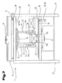
- a picking system is shown in perspective view, which is a device 1 for loading a load carrier 2 with a loading stack 3 forming loading units 4, a feeder 5, a lifting station 6 for raising and lowering a load carrier 2 and a conveyor 7, 8 for transporting empty charge carrier. 2 and removal of loaded charge carriers 2 and a loading aid 9 has.
- the conveyor 7, 8 is formed by a roller conveyor, belt conveyor and the like .
- the lifting station 6 is provided with a arranged on a liftable and lowerable lifting table 10 carrier change device 11, which is formed according to this embodiment by a drivable roller conveyor. In the lowered change position of the charge carrier changing device 11, a loaded load carrier 2 can be delivered to the conveyor 7 or an empty load carrier 2 can be received by the conveyor 8.
- the picking system has according to this embodiment also in the Fig. 13 picking station 12 described in more detail on.
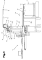
- the device 1 for automated loading of the charge carrier 2 ( Fig. 1 ), in particular an order pallet, with the required for a picking order loading units 4 shown in different views.
- the device 1 has a positioning conveyor 16, a feed conveyor 17, an alignment device 18 and a load monitoring device 19.
- the feed conveyor 17 is mounted on a carriage 20, which has a support frame.
- the support frame comprises an upper support 21 and lower support 22 and between them at a distance parallel extending support arms 23.
- the Stellwagen 20 is connected via an adjusting device 24 along a guide arrangement in the x-direction 25 horizontally along the charge carrier 2 (FIG. Fig. 1 ) mounted on a base frame 26 of the device 1 adjustable.
- the base frame 26 has uprights 27 and these connecting cross member 28.
- the guide arrangement is disposed between the cross members 28 and the upper carrier 21 of the carriage 20 and formed by linear guides 29.
- adjusting device 24 shown is formed by a linear drive and has according to the embodiment shown on a traction drive.
- the traction mechanism drive comprises an endlessly circulating traction mechanism 30, which is guided around a deflecting wheel and a drive wheel coupled to a servomotor 31.
- the traction means 30 is formed for example by a toothed belt, a chain or the like.
- a driving slide 32 is fixed, which is coupled to the support frame of the carriage 20.
- the positioning carriage 20 and the feed conveyor 17 mounted thereon are moved horizontally along the x-direction relative to the load carrier 2 to an x-position in the loading stack 3 determined by a computer system (warehouse management computer).
- a computer system warehouse management computer
- the feed conveyor 17 comprises a linear conveyor, in particular a belt conveyor 33 driven by a conveyor motor 36, belt conveyors and the like, and a slide bar 34 arranged at a small distance at the front end parallel to its front edge.
- the belt conveyor 33 forms a loading unit 4 in the conveying direction 35 front end inclined downwardly extending conveying plane.
- the slide strip 34 has a conveying direction 35 of the loading units 4 inclined to its front end downwardly extending transfer plane, wherein the conveying plane of the belt conveyor 33 and the transfer plane of the slide strip 35 enclose an angle greater than 180 °.
- the alignment device 18 has side guides which are adjustable relative to one another and are formed by conveying devices 40a, 40b, in particular belt conveyors, belt conveyors and the like, spaced apart parallel to one another in the conveying direction 35 of the loading units 4.
- Each conveyor 40a, 40b is coupled to a drive motor 41a, 41b.
- the rotational speed of the conveying devices 40a, 40b corresponds approximately to the rotational speed of the belt conveyor 33.
- loading units 4 of very different dimensions, geometries, dimensional stability, surface quality and / or lengths / widths / height ratios are usually to be picked within the picking system. If a picking order has loading units 4 of different widths 42 (dimensions), the conveying devices 40a, 40b are adjusted accordingly.
- the width is to be understood as the width 42 reduced by the deflection.
- the right-hand conveyor 40a is fixedly arranged on the support frame of the carriage 20, while the left-hand conveyor 40b is adjustable relative to the positioning conveyor 17 in the x-direction.
- the left conveyor 40b is disposed on a carriage 43 having a support frame.
- the support frame comprises a frame 37 and cantilevers 38.
- the actuator 43 is mounted on an adjusting device 44 along a guide assembly in the x-direction 25 adjustable on the positioning carriage 20 of the positioning 17.
- the guide arrangement is formed by linear guides 45, which are arranged between the upper carrier 21 of the carriage 20 and the cantilevers 38 of the carriage 43.
- the adjusting device 44 is formed by a linear drive and, according to the embodiment shown, has a traction mechanism drive.
- the traction mechanism drive comprises an endlessly circulating traction mechanism 46, which is guided around a deflecting wheel and a drive wheel coupled to a servomotor 47.
- the traction means 46 is formed for example by a toothed belt, a chain or the like.
- a driving slide 48 is fixed, which is coupled to the support frame of the carriage 43.
- the direction of rotation of the servo motor 47 is reversible, so that the positioning carriage 43 and thus the conveying device 40b in the x-direction is either moved towards the opposite conveying device 40a or moved away from it.
- the right-hand conveying device 40a to be adjustable in the x direction via the adjusting device relative to the positioning conveying device 17, and for both conveying devices 40a, 40b to be synchronized with one another or moved away from one another.
- This has the advantage that differently wide loading units 4 are positioned centrally on the feed conveyor 17.
- the positioning conveyor 16 has parallel conveyor tracks 50a, 50b which are each arranged on a guide slide 51a, 51b and are mounted on the base frame 26 of the device 1 so as to be adjustable in the x-direction via a first adjustment device 52 along a guide arrangement into a transfer position.
- the conveyor tracks 50a, 50b are set to a distance 53 determined by the computer system from the conveying property of the load unit 4 to be stacked and positioned below the loading conveyor 17 such that a loading unit 4 lying on the load conveyor 17 is centered relative to the conveyor tracks 50a, 50b can be handed over.
- the support points for the loading unit 4 are optimally adjusted by the variable distance 53 between the conveyor tracks 50a, 50b. It has been shown, in particular in the case of limp loading units 4, that when the loading unit 4 rests on the conveyor tracks 50a, 50b, each with a lateral projection of about 15% to 25% of the width 42, at the section of the loading unit 4 between the conveyor tracks 50a, 50b and at the protruding portions of the loading unit 4, an approximately same deflection of the loading unit 4 results.
- the guide arrangement is formed by linear guides 54, which is arranged between the guide carriages 51 a, 51 b and cross members 55 of the base frame 26.
- the adjusting device 52 is formed by a linear drive and, according to the embodiment shown, has a first and second traction mechanism drive.
- the first traction mechanism drive comprises an endlessly circulating traction mechanism 56, which is guided around a deflecting wheel and a drive wheel coupled to a servomotor 57.
- the traction means 56 is formed, for example, by a toothed belt, a chain or the like and with which the conveyor track 50a overlapping Guide carriage 51a is firmly connected.
- the second traction mechanism drive comprises an endless circulating traction mechanism 58, which is guided around a deflecting wheel and a drive wheel coupled to a servomotor 59.
- the traction means 58 is formed for example by a toothed belt, a chain or the like. And with the conveyor track 50b overlapping guide carriage 51 b is firmly connected. By turning the drive wheels in a clockwise or counterclockwise direction, the conveyor tracks 50a, 50b are moved in the x-direction to their transfer position.
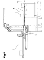
- the conveyor tracks 50a, 50b are also connected in the z-direction (depth direction of the load carrier 2) by means of a second adjusting device 60 between an in Fig. 3 shown, retracted takeover position and a in Fig. 4 shown, extended loading position approximately synchronously adjustable.
- the conveyor tracks 50a, 50b protrude in their transfer position in the z-direction at the front end of the feed conveyor 17.
- the conveyor tracks 50a, 50b are positioned such that a loading unit 4 is moved to an x and z position defined in the loading stack 3 by the computer system.
- the extension movement of the conveyor tracks 50a, 50b is made possible by the adjusting device 60, which is formed by a linear drive and has a first and second traction mechanism drive according to the embodiment shown.
- the traction mechanism drives each comprise an endlessly circulating traction means 65a, 65b, which is guided around a deflection wheel and a drive wheel.
- the drive wheels are coupled via a not further shown drive shaft to a common displacement motor 66. But just as well, each drive wheel can be coupled to a displacement motor.
- the traction means 65a, 65b are formed for example by a toothed belt, a chain or the like, to which a coupling slide 67a, 67b is attached.
- the traction drives are each mounted on a frame 68a, 68b, of which the right frame 68a with the conveyor track 50a overlapping guide carriage 51a and the left frame 68b with the conveyor track 50b overlapping guide carriage 51b is firmly connected.
- the displacement motor 66 is fixed to the frame 68a.
- the conveyor tracks 50a, 50b are each mounted on the guide carriages 51a, 51b via a guide arrangement, in particular a linear guide 69a, 69b shown in the figures, and connected to the coupling carriage 67a, 67b with their rear end in the extension direction 70.
- the direction of rotation of the displacement motor 66 is reversible, so that according to the direction of rotation extend the conveyor tracks 50a, 50b with a loading unit 4 loaded thereon to the intended z-position in the loading stack 3 ( Fig. 4 ) and then to retract for receiving a loading unit 4 in the takeover position ( Fig. 3 ).
- the conveyor tracks 50a, 50b each have a linear conveyor with a conveyor 71, in particular conveyor belt, conveyor belt and the like, which are coupled to a common conveyor motor 72.
- the conveying motor 72 is fixed to the frame 68a. But just as well, each conveyor 71 can be driven by a conveyor motor.
- the right conveyor track 50a is attached to the carriage 20 of the feed conveyor 17 and only the left conveyor track 50b in the x-direction adjustable.
- the adjusting device 52 only has the second traction mechanism drive.
- the first traction drive can be omitted, which simplifies the overall structure of the adjustment 52.
- a support profile 73 is fastened to the cross member 28 of the base frame 26.
- a guide profile 74 On the support section 73 is a guide profile 74, on which a via an adjusting device 75 in the x-direction slidably support arm 76 is mounted.
- the adjusting device 75 has a servo motor 77 and a traction mechanism drive not shown further, the traction means is connected to the support arm 76.
- the load monitoring device 19 for detecting the loading state such as the current height of the loading stack 3 and / or a loading pattern is arranged in a stacking position, which is formed in the form of an optoelectronic or acoustic scanning device 78, in particular a scanner ,
- the loading units 4 required for a picking order do not have a illustrated automated conveyor technology, for example, a shelf vehicle taken from a warehouse and fed to the device 1 in the loading zone.
- the loading units 4 are loaded onto the charge carriers 2, in particular order pallets, via the apparatus 1, the finished loading stacks 3 are wound on a film winding machine (not shown) for stabilization with securing means, such as a film, strips or the like, and finally on a Truck loaded.
- an identification code of the loading units 4 is detected and determined by the warehouse management computer to each loading unit 4 whose stored delivery property.
- the conveying properties are determined by the dimension, geometry, dimensional stability, surface texture and / or a length / width / height ratio and the like.
- the loading unit 4. From these data, the loading management positions for the loading units 4 in the loading stack 3 are determined by the warehouse management computer in addition to the above-described distance adjustment of the conveying devices 40a, 40b and conveying paths 50a, 50b, therefore an x-position, y-position and z-position for each loading unit 4 set in the charging stack 3.
- the loading positions are determined by the warehouse management computer taking into account various aspects.
- the finished charging stack 3 should be as stable and easy to transport as possible, therefore heavy loading units 4 are positioned below in the charging stack 3 and lighter loading units 4 above in the charging stack 3. Likewise, more sensitive loading units 4 are accommodated at the top in the loading stack 3. Also, the loading stack 3 should be packed as close as possible and as high as possible. If the loading positions 4 optimized for the stability and / or volume utilization of the loading stack 3 are now calculated, a loading order is determined by the warehouse management computer. The loading units 4 are conveyed one after the other to the feed conveyor 17 in succession by the feeder 5 in accordance with this sequence.
- the loading positions (x, y and z positions) for the loading units 4 in the loading stack 3 are determined on the basis of the loading condition detected by the loading monitoring device 19 and depending on the loading units 4 in the appropriate order isolated the feed conveyor 17 conveyed.
- the charging unit 4 to be stacked is possibly even before being transferred to the in the z-direction at the front end of the feed conveyor 17 projecting and moved into the transfer position conveyor tracks 50a, 50b between the relatively adjustable conveyor devices 40a, 40b aligned in the conveying direction 35 of the loading units 4 parallel direction.
- the conveying device 40b is delivered to the opposite conveying device 40a so far that the distance between the conveying devices 40a, 40b is slightly greater than the width 42 of the loading unit 4 or exactly corresponds to the width 42 of the loading unit 4.
- the conveying devices 40a, 40b can also be adjusted to a distance which substantially corresponds to the width 42 reduced by the deflection.
- the positioning carriage 20 is moved in the x-direction so far that the loading unit 4 is located at the intended x-position in the loading stack 3.
- the conveyor tracks 50a, 50b are still moved to the transfer position in which the distance 53 determined from the conveyance characteristic of the loading unit 4 to be transferred is set and the loading unit 4 is set relative to the conveyor tracks 50a, 50b can be handed over in the middle. Thereafter, the loading unit 4 is conveyed from the loading conveyor 17 to the positioning conveyor 16.
- the conveyor tracks 50a, 50b of their in Fig. 3 shown takeover position relative to the feed conveyor 17 in the in Fig. 4 extended loading position shown in which the resting on the conveying means 71 loading unit 4 is above its intended x and z position in the charging stack 3.
- the loading unit 4 can be positioned on the positioning conveyor 16 by driving the conveying means 71, in particular transported to its front end, as is preferably expedient for loading units 4 of smaller dimension.
- the conveyor tracks 50a, 50b are bent back together with the conveying means 71 in the return direction 79, wherein at the same time the conveying means 71 on the support side over the Conveyor motor 72 is driven against the return direction 79 in the conveying direction 35 of the loading units 4.
- the conveying speed of the conveying means 71 corresponds in magnitude to the reversing speed of the conveying paths 50a, 50b, so that the conveying means 71, in particular the conveyor belts are adjusted below the bottom of the loading unit 4 without relative displacement to the loading unit 4.
- the loading unit 4 is withdrawn its support on the conveyor 71, so that it tilts with their rear in the direction 79 rear end on the lower level loading level 80 of the carrier 2 or a stack layer, as in Fig. 5 shown.
- the charging unit 4 to be stacked should rest as close as possible to a loading unit 4 already present in the stacking position or a wall part of the loading aid 9 in the z-direction. This is achieved when the conveying speed of the conveyor 71 is slightly greater than the return speed of the conveyor tracks 50a, 50b.
- the loading operation is completed when the loading unit 4 rests on the loading level 80 and the conveying means 71 are completely moved under the loading unit 4, as in Fig. 6 shown.
- the receiving table 10 is moved downwards in the y-direction, whereupon a renewed position in the loading stack 3 can be created.
- a loading aid 9 is provided, which surrounds the forming stack of charges 3 from three sides and can serve as a support surface for a sliding movement of the loading unit 4 in the horizontal direction.
- the movements of the loading units 4 on the feed device 5, positioning conveyor 16 and the feed conveyor 17 are decoupled.
- the positioning conveyor 16 is moving a loading unit 4 to the loading position
- the next loading unit 4 is moving from the loading conveyor 17 in the fixed x-direction and / or while the loading conveyor 17 is moving a loading unit 4 in the specified x-direction
- the next loading unit 4 is moved to the front end of the feeder 5.
- the throughput of the device 1 can be increased.
- a gap width 81 is calculated by the computer system when determining the loading positions of the loading units 4 or detected by the load monitoring device 19.
- the gap width 81 is preferably detected before the transfer of a loading unit 4 onto the loading stack 3, in particular to the stack gap in a stacking position, and the adjustment system 52 is controlled by the computer system such that the conveying paths 50a, 50b are relative to one another in the x direction on the basis of the gap width 81 moved and set to the distance 53 described below.
- the conveyor tracks 50a, 50b are preferably moved synchronously and in opposite directions for spacing adjustment.
- the gap width 81 may be only a few millimeters too narrow than would be required to accommodate a 42 load unit 4.
- a safety distance 82 between the side walls 83 of the loading unit 4 still to be stacked and the loading unit 4 already present in the stacking position or laterally between the conveyor tracks 50a, 50b and the side walls 83 of the loading units 4 already present in the stacking position may also be required for security against collision be.
- the safety distance 82 is based on the fact that a customer order usually not only loading units 4 with particularly dimensionally stable side walls 83, but also with easily deformable side walls 83 and thereby bulges arise or skew the side walls 83 results.
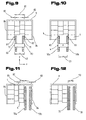
- the conveyor tracks 50a, 50b in the in Fig. 9 registered loading position in the z-direction between the loading units 4 extended.
- the conveyor tracks 50a, 50b are in the loading position in the x direction at least by the lateral safety distance 82 of the optionally curved side walls 83 away. This is achieved by the adjustment of one or both conveyor tracks 50a, 50b in the x-direction.
- the relatively adjustable conveyor tracks 50 a, 50 b in the x direction in an in Fig. 10 Sp Gill ein shown moves apart, thereby forming the optionally curved side wall 83 of the stacked loading unit (s) 4 reformed.
- the conveyor tracks 50a, 50b are set to the distance 53 in the x direction.
- the distance 53 is set before a loading unit 4 is discharged from the positioning conveyor 16 to the stacking gap.
- the maximum distance 53 is determined in which, if necessary, taking into account the above-mentioned conveying properties yet reliable support of the loading unit 4 on the conveyor tracks 50a, 50b is ensured.
- the x-displacement path of the conveyor tracks 50a, 50b between the distance 53 set on the basis of the conveying properties and the distance 53 set using the gap width 81 will be only a few millimeters to centimeters, so that, on the one hand, reliable loading of the loading unit 4 and, on the other hand, a high loading density in the loading stack 3 is achieved. If a secure loading of the loading unit 4 can not be guaranteed, since the maximum distance 53 is too large, this loading unit 4 may not be unloaded at the stack gap but at another free point in the loading stack 3.
- the gap width 81 can be increased at least to the width 42 of the stacking loading unit 4, after which the loading unit 4 can be conveyed into the gap without collision.
- the conveyor tracks 50a, 50b remain in their spread position until the loading unit 4 has been conveyed to the predetermined z-position. Thereafter, the conveyor tracks 50a, 50b are again moved toward one another in their loading position in the x-direction and in the direction of the transfer position (FIG. Fig. 3 ) and thereby the loading unit 4 on the loading level 80 (not entered) stored exactly at the z-position.
- a loading pattern can arise in which a gap between a wall portion 84 of the loading aid 9 and a loading unit 4 is formed within a stacking position. In this case, only those of the loading unit 4 adjacent conveyor track 50a, 50b adjusted to the spread and delivered to the side wall 83, thereby widening the gap.
- FIGS. 11 and 12 It can be seen from the loading pattern that results in a gap 82 resulting from the safety distance 82 between the second and third row of stacked loading units. This occurs when the loading stack 3 is built from bottom to top and each loading platform layer from back to front and from left to right or from right to left on the carrier 2.
- the conveyor tracks 50a, 50b in the z-direction in a loading position are extended and then the left conveyor track 50a in the spread position ( Fig. 12 ) is moved.
- the loading units 4 of the third row are pressed against the loading units 4 of the second row and the spacing gap 85 is minimized to approximately zero.
- the conveyor tracks 50a, 50b are set to the distance 53 in the x direction.
- the left conveyor 50a is again returned to its loading position in the x-direction, as in Fig. 12 inscribed in dotted lines.
- a loading unit 4 is transferred from the feed conveyor 17 to the positioniter conveyor 16 and conveyed via the conveyor 71 to the predetermined z-position in the loading stack 3 and delivered in the manner described above at this position to the loading level 80 (not registered).
- the conveyor tracks 50a, 50b set to the distance 53 and then extended taking into account the safety distance 82 with the loading unit 4 in the z direction until the loading unit 4 the achieved z-position and then pressed by a movement of the conveyor tracks 50a, 50b in the x direction, this loading unit 4 with its side wall 83 against the already present in the stacking loading unit 4 side.
- the distance 53 is set automatically by the computer system according to the above statements on the basis of at least one conveying property of the loading unit 4 and / or a stacking property or a loading pattern in the loading stack 3, in particular a gap width 81 of a stack gap.
- the apparatus 1 described above is also suitable for manual loading of a load carrier 2 with the loading units 4.
- the order picking station 12 is provided, on which a picking person works and removes the loading units 4 delivered by the conveying tracks 50a, 50b to the positioning conveyor 16 by means of a loading position shown and onto the load carrier 2 or an already stacked layer stores.
- a distance between the conveyor tracks 50a, 50b is again advantageously set, which is determined from the conveying property of the load unit to be stacked.
- the conveyor tracks 50a, 50b are moved into a parking position during the manual loading, so that the picking person can work unhindered at the picking station 12. This makes efficient picking possible even in manual mode. Via a staircase the picking person access to the picking station 12 is possible, which is located on a tribune.
- the conveyor tracks 50a, 50b, on which a loading unit 4 is provided, are arranged at gripping height, in particular at the chest or hip height of the picking person.
- a further embodiment of the device 1 of the commissioning system according to the invention is shown in a schematic representation.
- the device 1 for loading a load carrier 2 with loading units 4 forming a loading stack 3 differs from the embodiment described in the preceding FIG.
- a feeder conveyor 90 is also arranged between the stationary feeder 5 and the feeder conveyor 17 which can be adjusted in the x direction.
- the positioning conveyor 16 of the device 1 is formed either separately from the feed conveyor 17 according to the preceding embodiment, but adjustable in synchronism with the feed conveyor 17 in the x-direction (coupled adjustment), or via a not shown first adjustment on the support frame of the carriage 20 of the feed conveyor 17 stored and with this together in the x-direction adjustable.
- the distance 53 can be set in the manner described above.
- the positioning conveyor 16 and feed conveyor 17 are adjusted together as a unit in the x-direction.
- the device 1 again has the alignment device 18, which comprises the lateral side guides, for example conveying devices 40a, 40b or centering devices and the like, spaced apart parallel to one another in the conveying direction 35 of the loading units 4, by means of which a loading unit 4 can be positioned and centered relative to the belt conveyor 33 in the x-direction.
- the alignment device 18 comprises the lateral side guides, for example conveying devices 40a, 40b or centering devices and the like, spaced apart parallel to one another in the conveying direction 35 of the loading units 4, by means of which a loading unit 4 can be positioned and centered relative to the belt conveyor 33 in the x-direction.
- the feeder conveyor 90 is formed, for example, by a roller conveyor, belt conveyor and the like and is mounted via an unregistered adjustment along a guide arrangement between a transfer position and a transfer position in the x-direction adjustable on a base frame.
- Fig. 14a the first loading unit 4.1 is conveyed by the stationary feeder 5 to the feeder conveyor 90 adjusted in the x direction in the transfer position. Thereafter, the feeder conveyor 90 is moved to the transfer position in the x direction and the first loading unit 4.1 is conveyed in the direction of the feed conveyor 17 to a transfer position, as in Fig. 14b shown, therefore, the first loading unit 4.1 is positioned in the x direction.
- the positioning of the first loading unit 4.1 in the x-direction takes place in a first loading cycle such that the loading unit 4.1 is already in the transfer position in the loading position defined in the loading stack 3 in the transfer position in the x-direction, as in FIG Fig. 14b shown.
- the positioning and feeding conveyors 16, 17 are positioned in the x-direction and the conveyor tracks 50a, 50b set to the above-described distance 53 and positioned below the loading conveyor 17 such that the first loading unit 4.1 is centered relative to the conveyor tracks 50a, 50b can be.
- the first loading unit 4.1 from the feeder conveyor 90 conveyed to the feed conveyor 17 and preferably between the side guides, such as conveyors 40 a, 40 b, aligned in the x direction.
- the feeder conveyor 90 is moved from its transfer position to the transfer position in the x direction and taken over by it a second loading unit 4.2.
- the optionally aligned first loading unit 4.1 is taken over by the positioning conveyor 16 adjusted in the transfer position.
- the conveyor tracks 50a, 50b are retracted together with the conveying means 71 in the return direction 79, wherein at the same time the conveying means 71 are driven on the support side against the return direction 79 in the conveying direction 35 of the loading unit 4.1.
- the loading unit 4.1 is stored in the manner described above on the carrier 2 or a stack layer.
- the first loading cycle is completed when the loading unit 4.1 has been stored and the conveying means 71 have moved completely under the loading unit 4.1.
- the loading cycle of the second loading unit 4.2 is already started during the loading cycle of the first loading unit 4.1.
- a second loading unit 4.2 is conveyed / provided on the feeder 5, and meanwhile the feeder conveyor 90 is moved out of its in Fig. 14b shown transfer position in the in Fig. 14c shown transfer position in x-direction.
- the second loading unit 4.2 from the feeder 5 promoted to the feeder conveyor 90.
- the second loading unit 4.2 is located on the feeder conveyor 90, it is again moved into the transfer position and the second loading unit 4.2 is conveyed in the direction of the loading conveyor 17 into a transfer position, as in FIG Fig. 14e shown.
- the positioning of the second loading unit 4.2 in the x-direction takes place in the second loading cycle such that the second loading unit 4.2 is not yet in the transfer position in the loading position 3 in the transfer stack 3 in the transfer position in the x-direction.
- Fig. 14f can be removed, the Zuteilanni listening 90 is moved in the x direction in the transfer position in which the second loading unit 4.2 is in the transfer position corresponding to the defined by the computer system for the first loading unit 4.1 loading position in the loading stack 3 in the x direction. Accordingly, the transfer position is independent of the subsequent loading position of the second charging unit 4.2 in the charging stack 3 in the x direction.
- the second loading unit 4.2 is located on the loading conveyor 17, it is conveyed by an adjusting movement of the loading conveyor 17 to the fixed loading position in the x-direction and aligned by the lateral guides, for example conveying devices 40a, 40b, as in FIG Fig. 14h shown.
- the positioning conveyor 16 is positioned in the x-direction and the conveyor tracks 50a, 50b adjusted to the above-described distance 53 and positioned below the feed conveyor 17, that the second loading unit 4.1 relative to the conveyor tracks 50a, 50b on the adjusted in the transfer position positioning 16 can be handed over in the middle.
- the loading cycle of the third loading unit 4.3 is already started during the loading cycle of the second loading unit 4.2.
- the feeder conveyor 90 is moved out of its transfer position (FIG. Fig. 14g ) into the takeover position ( Fig. 14h ) in the x-direction and taken from her a third loading unit 4.3, as in Fig. 14h shown. If the third loading unit 4.3 is located on the feeder conveyor 90, it moves again into the transfer position, in which the third loading unit 4.3 is in the transfer position, as in FIG Fig. 14i In this case, the transfer position is defined either by the loading position of the currently conveyed loading unit 4.3 or preceding loading unit 4.2 or by the actual position of the feed conveyor 17 in the x direction.
- This process or the loading cycles are repeated until the loading stack 3 has been completed on one or more load carriers 2 for a customer order.
- the transfer position of the feeder conveyor 90 can be determined by the computer system and the feeder conveyor 90 in this process become.
- the transfer position for a loading unit is defined by the actual position of the loading conveyor 17 in the x-direction
- the travel of the feed conveyor 17 in the x-direction is detected and the feeder conveyor 90 moves relative to the feed conveyor 17 on the basis of the detected actual position and thereby the loading unit provided in the x-direction in the transfer position.
- the detection of the travel path via a not-shown displacement measuring system, by means of which the actual position of the carriage 20 is detected by sensors.
- the displacement measuring system is formed by a known capacitive transducer, inductive displacement transducer, magnetic transducer or optoelectronic transducer. In doing so, one makes use of the measuring method of absolute or incremental distance measurement.
- the servomotor 31 can be provided for the adjustment carriage 20, for example with a resolver or incremental encoder as a positioning system, by means of which the actual position of the carriage 20 is permanently detected.
Description
- Die Erfindung betrifft ein Kommissioniersystem nach dem Oberbegriff des Anspruchs 1 und ein Verfahren nach den korrespondierenden Ansprüchen 10 und 11 zum manuellen oder automatisierten Beladen eines Ladungsträgers, insbesondere einer Palette, mit einen Ladestapel bildenden Ladeeinheiten.
- Aus der gattungsgemäßen
NL 1 023 904 C2 - Eine Vorrichtung zum automatisierten Beladen eines Ladungsträgers mit einen Ladestapel bildenden Ladeeinheiten ist aus der
EP 1 462 394 B 1 bekannt, die eine Zuführeinrichtung, eine ortsfeste Ladeplatte, eine Beschickungsfördereinrichtung zum Verschieben einer Ladeeinheit auf und relativ zu der ortsfesten Ladeplatte in einer Richtung (x-Richtung) horizontal längs des Ladungsträgers und eine Positionierfördereinrichtung zum Ergreifen einer Ladeeinheit auf der Ladeplatte und zum Verfahren der Ladeeinheit in Richtung der Ladetiefe des Ladungsträgers (z-Richtung) sowie einen oberhalb der Positionierfördereinrichtung angeordneten Abstreifer aufweist, der unabhängig von der Positionierfördereinrichtung in z-Richtung verfahrbar ist und zum Rückhalten der Ladeeinheit an der gewünschten Position auf dem Ladestapel dient. Der Ladungsträger wird nach einer bezüglich der Stabilität und/oder Volumenausnutzung optimierten, räumlichen Beladungskonfiguration der Ladeeinheiten im Ladestapel beladen. Aus der Beladungskonfiguration wird eine Beladungsreihenfolge ermittelt, entsprechend der die Ladeeinheiten auf die ortsfeste Ladeplatte vereinzelt angefördert werden, wo eine einzelne Ladeeinheit von der Beschickungsfördereinrichtung in x-Richtung bis zu der vorgesehenen x-Position der Ladeeinheit in der Beladungskonfiguration des Ladestapels bewegt wird. Anschließend wird die Ladeeinheit mittels des Abstreifers auf die in z-Richtung vorragende Positionierfördereinrichtung geschoben und mittels dieser in z-Richtung bis zu der vorgesehenen z-Position in der Beladungskonfiguration des Ladestapels bewegt. Danach wird die Positionierfördereinrichtung zurückgefahren, während der Abstreifer zunächst in seiner Position verharrt, wodurch die Ladeeinheit an der für diese vorgesehene z-Position auf dem Ladestapel abgelegt wird. Anschließend werden die Positionierfördereinrichtung und der Abstreifer wieder zurückgefahren. Die Positionierung einer Ladeeinheit im Ladestapel in y-Richtung wird durch Anheben bzw. Absenken des Ladungsträgers erreicht. - Aus der
JP 11-020945 A - Die bekannten Vorrichtungen zum automatisierten Beladen eines Ladungsträgers verwenden eine Positionierfördereinrichtung mit einer auf das vielseitige Spektrum der Ladeeinheiten festgelegten Breite. Die Breite wird an die Ladeeinheit größter Dimension angepasst, sodass eine Lücke in einer Stapellage zwischen bereits auf den Ladungsträger gestapelten benachbarten Ladeeinheiten oder zwischen einer Ladeeinheit und einem Wandteil einer Stapelhilfe nicht bedient werden kann, wenn die Breite der Positionierfördereinrichtung größer ist als eine Lückenweite. Aufgrund der verbleibenden Lücken zwischen den Ladeeinheiten oder im Randbereich des Ladestapels, ist eine Optimierung der Volumenausnutzung im Ladestapel nur beschränkt möglich.
- Die
EP 0 799 780 A1 beschreibt eine Vorrichtung zur Beladung eines Ladungsträgers, bei der die auf einer Zuführeinrichtung angeförderten Ladeeinheiten von einer Ausrichtvorrichtung zwischen Ausrichtplatten relativ zur Zuführeinrichtung positioniert werden. - Aus der
DE 30 17 612 A1 ist ein Kommissioniersystem bekannt, bei dem Schächte über eine Positionierfördereinrichtung mit Ladeeinheiten beschickt werden, wobei die Positionierfördereinrichtung eine in Förderrichtung der Ladeeinheiten zu deren vorderen Ende geneigt nach unten verlaufende Förderebene ausbildet. - Auch sind aus dem Stand der Technik Kommissioniersysteme bekannt, bei denen Ladeeinheiten manuell auf einen Ladungsträger gestapelt werden. Die Ladeeinheiten werden vereinzelt auf einer Positionierfördereinrichtung bereitgestellt, von einer Kommissionierperson ergriffen und auf dem Ladungsträger an geeigneten Beladepositionen gestapelt. Für die Kommissionierperson ergeben sich ergonomisch ungünstige Bedienungen, insofern als die Zugänglichkeit und Greifbarkeit der Ladeeinheiten unberücksichtigt bleibt.
- Aufgabe der Erfindung ist es, eine Vorrichtung und ein Verfahren zum manuellen bzw. automatisierten Beladen eines Ladungsträgers mit Ladeeinheiten zu schaffen, das sich gegenüber dem Stand der Technik selbst bei Ladeeinheiten mit verschiedensten Eigenschaften, wie Dimensionen, Beschaffenheit und dgl., noch effizienter gestalten lässt.
- Die Aufgabe der Erfindung wird durch die Merkmale und Maßnahmen der Ansprüche 1, 10 und 11 gelöst. Das Kommissioniersystem bzw. Kommissionierverfahren eignet sich zur manuellen oder automatisierten Beladung eines Ladungsträgers, insbesondere einer Auftragspalette mit Ladeeinheiten.
- Von Vorteil ist, dass durch die Abstandseinstellung zwischen den Förderbahnen eine zuverlässige Abstützung der Ladeeinheiten auf deren Bewegung bis an die Beladeposition auf dem Ladestapel erreicht wird. Sind lange Ladeeinheiten zu stapeln, werden die Förderbahnen soweit auseinander gefahren, dass eine Ladeeinheit zuverlässig an den Förderbahnen auflastet und nicht zwischen diesen hindurch rutscht. Sind hingegen schmale Ladeeinheiten zu stapeln, werden die Förderbahnen unter Freilassung eines Sicherheitsabstandes aufeinander zugestellt, sodass eine nahezu vollflächige Förderebene für eine Ladeeinheit entsteht. Der Abstand kann aber ebenso gut auch unter Berücksichtigung anderer Kriterien, insbesondere einer Fördereigenschaft der Ladeeinheit eingestellt werden. Mit anderen Worten kann die Abstandseinstellung auch in Abhängigkeit der Formstabilität (biegeschlaffe oder formstabile Ladeeinheit) oder Oberflächenbeschaffenheit der Ladeeinheiten festgelegt werden.
- Insbesondere ist es bei der manuellen Beladung auch möglich, dass einerseits die Ladeeinheiten auf zuverlässige Weise bis zu einem Kommissionierplatz gefördert werden und andererseits der Kommissionierperson eine komfortable Entnahme der Ladeeinheit von der Positionierfördereinrichtung ermöglicht wird. Die Entnahme durch die Kommissionierperson kann insbesondere dadurch erleichtert werden, dass die Ladeeinheit in ausreichendem Maße an den Förderbahnen seitlich vorsteht und mit den Händen von unten besonders gut ergriffen werden kann. Der Bedienperson werden damit ergonomisch günstige Bedingungen geschaffen.
- Zudem kann bei der automatisierten Beladung die Positionierfördereinrichtung auch Stapellücken zwischen Ladeeinheiten oder einer Ladeeinheit und einem Wandteil der Ladehilfe bedienen und diese mit einer passenden Ladeeinheit auffüllen. Damit kann gegenüber solchen aus dem Stand der Technik bekannten Beladungsprinzipien eine noch höhere Beladungsdichte im Ladestapel erreicht werden.
- Gemäß der Erfindung ist es vorgesehen, dass die Vorrichtung ferner eine ortsfeste Zuführeinrichtung für die Ladeeinheiten, eine dieser in Förderrichtung der Ladeeinheiten nachgeordnete und in einer Richtung (x-Richtung) horizontal längs des Ladungsträgers verstellbare Beschickungsfördereinrichtung zur Förderung der Ladeeinheiten auf die Förderbahnen sowie durch eine Verstellvorrichtung in einer Richtung (x-Richtung) horizontal längs des Ladungsträgers und relativ zur Beschickungsfördereinrichtung verstellbare Zuteilfördereinrichtung für die Ladeeinheiten aufweist, welche in Förderrichtung der Ladeeinheiten zwischen der Zuführeinrichtung und der Beschickungsfördereinrichtung angeordnet ist.
- Die Zuteilfördereinrichtung verbindet die ortsfeste Zuführeinrichtung und die in x-Richtung verstellbare Beschickungsfördereinrichtung, wodurch gleichzeitig mehrere Beladezyklen abgearbeitet werden können. So kann eine erste Ladeeinheit von der Beschickungsfördereinrichtung zur Positionierfördereinrichtung gefördert und von letzterer auf den Ladungsträger umgeladen werden, während in der Zwischenzeit von der Zuteilfördereinrichtung bereits eine zweite Ladeeinheit an einer Übergabeposition bereitgestellt wird. Die Zuteilfördereinrichtung kann gegenüber der Beschickungs- und Positionierfördereinrichtung in x-Richtung mit höherer Geschwindigkeit verfahren. Denn sollten geringfügige Relativverlagerungen der Ladeeinheit auf der Zuteilfördereinrichtung auftreten, kann die Ladeeinheit durch einen anschließenden Ausrichtvorgang wieder ausgerichtet/positioniert und mit hoher Positioniergenauigkeit von der Beschickungsfördereinrichtung auf die Positionierfördereinrichtung übergeben werden. Dadurch kann die Leistungsfähigkeit der Vorrichtung verbessert werden.
- Von Vorteil ist auch die Ausgestaltung nach Anspruch 2, da die Bewegungen der Positionierfördereinrichtung und der Beschickungsfördereinrichtung entkoppelt ausgeführt werden können und noch während die Positionierfördereinrichtung eine Ladeeinheit an die Beladeposition bewegt, bereits die nächste Ladeeinheit in x-Richtung an die für sie im Ladestapel vorgesehene x-Position bewegt werden kann.
- Gemäß der Ausbildung nach Anspruch 3 können die Förderbahnen in Tiefenrichtung des Ladungsträgers synchron ausfahren, um eine Ladeeinheit an die für sie vorgesehene z-Position zu transportieren.
- Vorteilhaft ist auch die Weiterbildung nach Anspruch 4, wodurch die Ladeeinheiten gegebenenfalls ausgerichtet und in exakter Lage an die Positionierfördereinrichtung abgegeben werden können.
- Die Ausrichtvorrichtung weist Seitenführungen auf, welche entweder exakt auf die Breite der zu stapelnden Ladeeinheit oder im Wesentlichen auf die Breite der zu stapelnden Ladeeinheit verstellt werden können. Werden die Seitenführungen exakt auf die Breite der Ladeeinheit verstellt, können durch deren Manipulation hervorgerufene Verformungen, insbesondere Ausbauchungen an jenen den Seitenführungen zugewandten Seitenwänden auf dem Transportweg entlang der Beschickungsfördereinrichtung beseitigt bzw. reduziert werden. Sind Seitenführungen durch Fördervorrichtungen gebildet und werden diese auf die Breite der Ladeeinheit verstellt, kann die Ladeeinheit mittels der Fördervorrichtungen reibschlüssig gefördert werden. Durch diese Maßnahme wird die Reibkraft auf die Ladeeinheit erhöht und dadurch eine zuverlässige Beförderung entlang der Beschickungsfördereinrichtung erreicht und eine gegebenenfalls verdrehte Ladeeinheit exakt parallel zu einer Belade- bzw. Förderrichtung ausgerichtet. Im Gegensatz dazu, können bei biegeschlaffen Ladeeinheiten die Seitenführungen auf einen Abstand eingestellt, welcher im Wesentlichen der um die Durchbiegung verringerten Breite entspricht.
- Gemäß der Ausführung nach Anspruch 5 kann eine Ladeeinheit ohne zusätzliche Mechanismen von der Beschickungsfördereinrichtung auf die an dieser in z-Richtung vorragende Positionierfördereinrichtung bewegt werden.
- Eine vorteilhafte Ausgestaltung der Erfindung ist auch im Anspruch 6 beschrieben. Bevorzugt schneiden sich die Förderebenen der Beschickungsfördereinrichtung und der Positionierfördereinrichtung und schließen einen Winkel kleiner 180° ein, wobei ein Winkel zwischen einer Horizontalen und der Förderebene der Positionierfördereinrichtung kleiner ist als ein Winkel zwischen einer Horizontalen und der Förderebene der Beschickungsfördereinrichtung. Dadurch kann eine Ladeeinheit unabhängig von deren Schwerpunktslage im Wesentlichen ruckfrei von der Beschickungsfördereinrichtung auf die Positionierfördereinrichtung übergeben werden. Durch die geneigte Förderebene über einen Längsabschnitt der Positionierfördereinrichtung wird ein kontrolliertes Absetzen einer Ladeeinheit auf dem Ladungsträger oder einer bereits vorhandenen Stapellage erreicht.
- Mit der leicht abfallenden Förderebene, wie im Anspruch 7 beschrieben, wird eine kontrollierte Schwerpunktsverschiebung von Ladeeinheiten erreicht, die einen Artikel mit instabiler Schwerpunktslage, wie eine Flüssigkeit, Pulver und dgl., enthalten, und damit eine Übergabe der Ladeeinheiten von der Beschickungsfördereinrichtung auf die Positionierfördereinrichtung ohne wesentlicher, trägheitsbedingter Verlagerungen selbst bei hohen Übergabegeschwindigkeiten sichergestellt.
- Nach einer Ausführung gemäß Anspruch 8 ist nun auch eine manuelle Beladung eines Ladungsträgers durch eine Kommissionierperson möglich.
- Gemäß Anspruch 9 wird eine Fördereigenschaft der Ladeeinheiten durch eine elektronische Erfassungseinrichtung erfasst, beispielsweise an einem Lagerverwaltungsrechner durch Eingabe von Kommissionieraufträgen oder über eine geeignete Sensorik, welche beispielsweise im Bereich der Zuführeinrichtung angeordnet ist und die Dimension, Geometrie, Formstabilität, Oberflächenbeschaffenheit und/oder ein Längen/Breiten/Höhenverhältnis, bevorzugt berührungslos mit opto-elektronisch oder akustisch wirkender Sensorik, wie Laser-, Infrarot-oder Ultraschallsensoren erfasst.
- Mit der Maßnahme nach Anspruch 12 werden eine besonders sanfte Übergabe einer Ladeeinheit auf eine Ladeebene des Ladungsträgers oder einer Stapellage und ein schonender Betrieb der Positionierfördereinrichtung ermöglicht.
- Von Vorteil ist auch die Maßnahme nach Anspruch 13, da im Gegensatz zu der aus dem Stand der Technik bekannten Beladung von Ladungsträgern nunmehr auch Lücken zwischen bereits am Ladungsträger vorhandenen Ladeeinheiten oder zwischen einer Ladeeinheit und einem Wandteil einer Ladehilfe innerhalb einer Stapellage mit einer oder mehreren Ladeeinheiten aufgefüllt werden kann und damit eine optimale Volumensausnutzung und Stabilität im Ladestapel erreicht wird. Nachdem die seitliche Andruckkraft der Förderbahn auf die Seitenwand der bereits am Ladungsträger vorhandenen Ladeeinheiten niedrig ist, kann die zu stapelnde Ladeeinheit, die in z-Position bereits in der Lücke positioniert ist, alleinig aufgrund der Schwerkraft zwischen den Seitenwänden der Ladeeinheiten oder der Seitenwand einer Ladeeinheit und einem Wandteil nach unten gleiten, währenddem die Förderbahnen in z-Richtung zurückgefahren werden. Die Förderbahn wird in der unteren Hälfte der Ladeeinheit an die Seitenwand angelegt, sodass die Seitenwand der noch zu stapelnden Ladeeinheit und die Seitenwand der bereits am Ladungsträger vorhandenen Ladeeinheit ausreichend überlappen und beim Abgleiten der Ladeeinheit die Seitenwände nicht verkanten. Außerdem wird durch den Reibkontakt zwischen den Seitenwänden der abzugebenden Ladeeinheit und der bereits vorhandenen Ladeeinheit letztere zurückgehalten und der Ladestapel stabilisiert, währenddem die Förderbahnen in z-Richtung zurückfahren.
- Mittels der Zuteilfördereinrichtung gemäß Anspruch 14 können gleichzeitig mehrere Beladezyklen abgearbeitet werden können. So kann eine erste Ladeeinheit von der Beschickungsfördereinrichtung zur Positionierfördereinrichtung gefördert und von letzterer auf den Ladungsträger umgeladen werden, während in der Zwischenzeit von der Zuteilfördereinrichtung bereits eine zweite Ladeeinheit an einer Übergabeposition bereitgestellt wird.
- Gemäß Anspruch 15 wird die Ladeeinheit von der Zuteilfördereinrichtung in einer Position bereitgestellt, die bereits der durch das Rechnersystem festgelegten Beladeposition der "aktuellen" Ladeeinheit im Ladestapel in x-Richtung entspricht.
- Die Maßnahme nach Anspruch 16 ist von Vorteil, da noch während des vorangegangenen Beladezyklus einer Ladeeinheit, insbesondere während der Ein- und Ausfahrbewegung der Positionierfördereinrichtung in z-Richtung, eine Ladeeinheit des nächsten Beladezyklus auf der Beschickungsfördereinrichtung aufgenommen werden kann.
- Zum besseren Verständnis der Erfindung wird diese anhand der nachfolgenden Figuren näher erläutert.
- Es zeigen:
- Fig. 1
- einen Ausschnitt aus einem Kommissioniersystem mit einer Vorrichtung zur automatisierten Beladung eines Ladungsträgers, in perspektivischer und vereinfachter Darstellung;
- Fig. 2
- die Vorrichtung zur automatisierten Beladung des Ladungsträgers nach
Fig. 1 , in perspektivischer Ansicht; - Fig. 3
- eine Seitenansicht auf die Vorrichtung zur Beladung eines Ladungsträgers gemäß den Linien III - III in
Fig. 2 , mit einer Zuführeinrichtung, Beschickungsfördereinrichtung, Ausrichtvorrichtung und Positionierfördereinrichtung in ihrer Übernahmestellung; - Fig. 4
- eine Seitenansicht auf die Vorrichtung nach
Fig. 3 mit der Positionierfördereinrichtung in ihrer Beladestellung; - Fig. 5 und 6
- eine Seitenansicht auf die Vorrichtung nach
Fig. 3 mit der aus ihrer Beladestellung in die Übernahmestellung zurückfahrenden Positionierfördereinrichtung; - Fig. 7 und 8
- eine Vorderansicht der Vorrichtung nach
Fig. 2 mit auf unterschiedlich breite Ladeeinheiten verstellten Förderbahnen und Seitenführungen einer Ausrichtvorrichtung; - Fig. 9 bis 12
- eine Draufsicht auf einen Ladungsträger mit auf ihm gestapelten Ladeeinheiten und eine Ladehilfe mit unterschiedlichen Beladungsmustern sowie in die Lücke zwischen den Ladeeinheiten bzw. einer Ladeeinheit und einem Wandteil der Ladehilfe eingefahrenen Förderbahnen, in schematischer Darstellung;
- Fig. 13
- ein Kommissioniersystem mit der Vorrichtung nach
Fig. 1 für einen manuellen Beladevorgang des Ladungsträgers durch eine Kommissionierperson, in perspektivischer Ansicht und vereinfachter Darstellung; - Fig. 14a-j
- ein Kommissioniersystem mit einer anderen Ausführung der Vorrichtung und eine Sequenzdarstellung der Beladezyklen, in Draufsicht und vereinfachter Darstellung.
- Einführend sei festgehalten, dass in den unterschiedlich beschriebenen Ausführungsformen gleiche Teile mit gleichen Bezugszeichen bzw. gleichen Bauteilbezeichnungen versehen werden, wobei die in der gesamten Beschreibung enthaltenen Offenbarungen sinngemäß auf gleiche Teile mit gleichen Bezugszeichen bzw. gleichen Bauteilbezeichnungen übertragen werden können. Auch sind die in der Beschreibung gewählten Lageangaben, wie z.B. oben, unten, seitlich usw. auf die unmittelbar beschriebene sowie dargestellte Figur bezogen und sind bei einer Lageänderung sinngemäß auf die neue Lage zu übertragen.
- In der
Fig. 1 ist ein Kommissioniersystem in perspektivischer Ansicht gezeigt, welches eine Vorrichtung 1 zum Beladen eines Ladungsträgers 2 mit einen Ladestapel 3 bildenden Ladeeinheiten 4, eine Zuführeinrichtung 5, eine Hubstation 6 zum Anheben und Absenken eines Ladungsträgers 2 und eine Fördertechnik 7, 8 zum Antransport leerer Ladungsträger 2 und Abtransport von beladenen Ladungsträgern 2 sowie eine Ladehilfe 9 aufweist. Die Fördertechnik 7, 8 ist durch einen Rollenförderer, Bandförderer und dgl. gebildet. Die Hubstation 6 ist mit einer auf einem heb- und senkbaren Hubtisch 10 angeordneten Ladungsträger-Wechseleinrichtung 11 versehen, die nach diesem Ausführungsbeispiel durch einen antreibbaren Rollenförderer gebildet ist. In abgesenkter Wechselposition der Ladungsträger-Wechseleinrichtung 11 kann ein beladener Ladungsträger 2 an die Fördertechnik 7 abgegeben oder aber ein leerer Ladungsträger 2 von der Fördertechnik 8 empfangen werden. - Das Kommissioniersystem weist nach dieser Ausführung auch einen in der
Fig. 13 näher beschriebenen Kommissionierplatz 12 auf. - In den
Fig. 2 bis 8 ist die Vorrichtung 1 zum automatisierten Beladen des Ladungsträgers 2 (Fig. 1 ), insbesondere einer Auftragspalette, mit den für einen Kommissionierauftrag benötigten Ladeeinheiten 4 in unterschiedlichen Ansichten gezeigt. Die Vorrichtung 1 weist eine Positionierfördereinrichtung 16, eine Beschickungsfördereinrichtung 17, eine Ausrichtvorrichtung 18 sowie eine Beladungsüberwachungseinrichtung 19 auf. - Die Beschickungsfördereinrichtung 17 ist auf einem Stellwagen 20 gelagert, der einen Tragrahmen aufweist. Der Tragrahmen umfasst einen oberen Träger 21 und unteren Träger 22 sowie sich zwischen diesen mit Abstand parallel erstreckende Tragarme 23. Der Stellwagen 20 ist über eine Verstellvorrichtung 24 entlang einer Führungsanordnung in x-Richtung 25 horizontal längs des Ladungsträgers 2 (
Fig. 1 ) verstellbar auf einem Grundrahmen 26 der Vorrichtung 1 gelagert. Der Grundrahmen 26 weist Steher 27 und diese verbindende Querträger 28 auf. Die Führungsanordnung ist zwischen den Querträgern 28 und dem oberen Träger 21 des Stellwagens 20 angeordnet und durch Linearführungen 29 gebildet. - Die in
Fig. 3 schematisch, dargestellte Verstellvorrichtung 24 ist durch einen Linearantrieb gebildet und weist nach gezeigtem Ausführungsbeispiel einen Zugmitteltrieb auf. Der Zugmitteltrieb umfasst ein endlos umlaufendes Zugmittel 30, welches um ein Umlenkrad und ein mit einem Stellmotor 31 gekuppeltes Antriebsrad geführt ist. Das Zugmittel 30 ist beispielsweise durch einen Zahnriemen, eine Kette oder dgl. gebildet. Am Zugmittel 30 ist ein Mitnahmeschlitten 32 befestigt, welcher mit dem Tragrahmen des Stellwagens 20 gekoppelt ist. Durch Drehbewegung des Antriebsrades im Uhrzeigersinn oder im Gegenuhrzeigersinn wird der Stellwagen 20 und die auf diesem gelagerte Beschickungsfördereinrichtung 17 horizontal längs und relativ zum Ladungsträger 2 in x-Richtung bis zu einer von einem Rechnersystem (Lagerverwaltungsrechner) festgelegten x-Position im Ladestapel 3 bewegt. - Die Beschickungsfördereinrichtung 17 umfasst eine Linearfördereinrichtung, insbesondere einen von einem Fördermotor 36 angetriebenen Bandförderer 33, Gurtförderer und dgl. und eine am vorderen Ende parallel zu dessen Stirnkante mit geringem Abstand angeordnete Gleitleiste 34. Der Bandförderer 33 bildet eine in Förderrichtung 35 der Ladeeinheiten 4 zu deren vorderen Ende geneigt nach unten verlaufende Förderebene aus. Die Gleitleiste 34 weist eine in Förderrichtung 35 der Ladeeinheiten 4 zu ihrem vorderen Ende geneigt nach unten verlaufende Übergabeebene aus, wobei die Förderebene des Bandförderers 33 und die Übergabeebene der Gleitleiste 35 einen Winkel größer 180° einschließen.
- Die Ausrichtvorrichtung 18 weist relativ zueinander verstellbare Seitenführungen auf, die nach diesem gezeigten Ausführungsbeispiel durch in Förderrichtung 35 der Ladeeinheiten 4 mit Abstand parallel zueinander angeordnete Fördervorrichtungen 40a, 40b, insbesondere Bandförderer, Gurtförderer und dgl. gebildet sind. Jede Fördervorrichtung 40a, 40b, ist mit einem Antriebsmotor 41a, 41b gekoppelt. Die Umlaufgeschwindigkeit der Fördervorrichtungen 40a, 40b entspricht annähernd der Umlaufgeschwindigkeit des Bandförderers 33.
- Wie im nachfolgenden noch genauer beschrieben wird, sind innerhalb des Kommissioniersystems üblicherweise verschiedenste Ladeeinheiten 4 unterschiedlichster Dimensionen, Geometrien, Formstabilität, Oberflächenbeschaffenheit und/oder Längen/Breiten/Höhenverhältnisse zu kommissionieren. Weist ein Kommissionierauftrag Ladeeinheiten 4 unterschiedlicher Breiten 42 (Dimensionen) auf, werden die Fördervorrichtungen 40a, 40b entsprechend verstellt.
- Es sei an dieser Stelle darauf hingewiesen, dass bei biegeschlaffen Ladeeinheiten 4 die Breite als um die Durchbiegung verringerte Breite 42 zu verstehen ist.
- Nach gezeigtem Ausführungsbeispiel ist die rechte Fördervorrichtung 40a ortsfest am Tragrahmen des Stellwagens 20 angeordnet, während die linke Fördervorrichtung 40b in x-Richtung relativ zur Positionierfördereinrichtung 17 verstellbar ist. Die linke Fördervorrichtung 40b ist auf einem Stellwagen 43 angeordnet, der einen Tragrahmen aufweist. Der Tragrahmen umfasst einen Rahmen 37 und Kragarme 38. Der Stellwagen 43 ist über eine Verstellvorrichtung 44 entlang einer Führungsanordnung in x-Richtung 25 verstellbar auf dem Stellwagen 20 der Positionierfördereinrichtung 17 gelagert. Die Führungsanordnung ist durch Linearführungen 45 gebildet, die zwischen dem oberen Träger 21 des Stellwagens 20 und den Kragarmen 38 des Stellwagens 43 angeordnet sind.
- Die Verstellvorrichtung 44 ist durch einen Linearantrieb gebildet und weist nach gezeigtem Ausführungsbeispiel einen Zugmitteltrieb auf. Der Zugmitteltrieb umfasst ein endlos umlaufendes Zugmittel 46, welches um ein Umlenkrad und ein mit einem Stellmotor 47 gekuppeltes Antriebsrad geführt ist. Das Zugmittel 46 ist beispielsweise durch einen Zahnriemen, eine Kette oder dgl. gebildet. Am Zugmittel 46 ist ein Mitnahmeschlitten 48 befestigt, welcher mit dem Tragrahmen des Stellwagens 43 gekoppelt ist. Die Drehrichtung des Stellmotors 47 ist reversibel ausgebildet, sodass der Stellwagen 43 und damit die Fördervorrichtung 40b in x-Richtung entweder auf die gegenüberliegende Fördervorrichtung 40a zu bewegt oder von dieser weg bewegt wird. Durch die Verstellung des Abstandes zwischen den Fördervorrichtungen 40a, 40b findet eine Anpassung an unterschiedliche Breiten 42 der Ladehilfsmittel 4 statt. Dadurch, dass vorzugsweise nur eine der Fördervorrichtungen 40a, 40b verstellt wird, vereinfacht sich der Aufbau der Verstellvorrichtung 44 und werden unterschiedlich breite Ladeeinheiten 4 stets gegen ein und dieselbe Referenzlinie an der ortsfesten Fördervorrichtung 40a positioniert.
- Andererseits ist es aber auch möglich, dass auch die rechte Fördervorrichtung 40a über die Verstellvorrichtung relativ zur Positionierfördereinrichtung 17 in x-Richtung verstellbar ist und beide Fördervorrichtungen 40a, 40b synchron aufeinander zugestellt oder voneinander wegbewegt werden können. Dies hat den Vorteil, dass unterschiedlich breite Ladeeinheiten 4 zentrisch auf der Beschickungsfördereinrichtung 17 positioniert werden.
- Die Positionierfördereinrichtung 16 weist parallele Förderbahnen 50a, 50b auf, die jeweils auf einem Führungsschlitten 51a, 51b angeordnet und über eine erste Verstellvorrichtung 52 entlang einer Führungsanordnung in eine Übernahmestellung in x-Richtung verstellbar auf dem Grundrahmen 26 der Vorrichtung 1 gelagert sind. In der Übernahmestellung sind die Förderbahnen 50a, 50b auf einen aus der Fördereigenschaft der zu stapelnden Ladeeinheit 4 vom Rechnersystem ermittelten Abstand 53 eingestellt und so unterhalb der Beschickungsfördereinrichtung 17 positioniert, dass eine auf der Beschickungsfördereinrichtung 17 liegende Ladeeinheit 4 relativ zu den Förderbahnen 50a, 50b mittig übergeben werden kann.
- Wie oben beschrieben, werden durch den variierbaren Abstand 53 zwischen den Förderbahnen 50a, 50b die Auflagepunkte für die Ladeeinheit 4 optimal eingestellt. Es hat sich insbesondere bei biegeschlaffen Ladeeinheiten 4 gezeigt, dass wenn die Ladeeinheit 4 an den Förderbahnen 50a, 50b jeweils mit einem seitlichen Überstand von etwa 15% bis 25% der Breite 42 aufliegt, sich am Abschnitt der Ladeeinheit 4 zwischen den Förderbahnen 50a, 50b und an den überstehenden Abschnitten der Ladeeinheit 4 eine annähernd gleiche Durchbiegung der Ladeeinheit 4 ergibt.
- Die Führungsanordnung ist durch Linearführungen 54 gebildet, die zwischen den Führungsschlitten 51a, 51b und Querträgern 55 des Grundrahmens 26 angeordnet ist.
- Die Verstellvorrichtung 52 ist durch einen Linearantrieb gebildet und weist nach gezeigtem Ausführungsbeispiel einen ersten und zweiten Zugmitteltrieb auf Der erste Zugmitteltrieb umfasst ein endlos umlaufendes Zugmittel 56, welches um ein Umlenkrad und ein mit einem Stellmotor 57 gekuppeltes Antriebsrad geführt ist. Das Zugmittel 56 ist beispielsweise durch einen Zahnriemen, eine Kette oder dgl. gebildet und mit dem die Förderbahn 50a lagernden Führungsschlitten 51a fest verbunden ist. Der zweite Zugmitteltrieb umfasst ein endlos umlaufendes Zugmittel 58, welches um ein Umlenkrad und ein mit einem Stellmotor 59 gekuppeltes Antriebsrad geführt ist. Das Zugmittel 58 ist beispielsweise durch einen Zahnriemen, eine Kette oder dgl. gebildet und mit dem die Förderbahn 50b lagernden Führungsschlitten 51 b fest verbunden ist. Durch Drehen der Antriebsräder im Uhrzeigersinn oder im Gegenuhrzeigersinn, werden die Förderbahnen 50a, 50b in x-Richtung bis in ihre Übernahmestellung bewegt.
- Die Förderbahnen 50a, 50b sind über eine zweite Verstellvorrichtung 60 auch in z-Richtung (Tiefenrichtung des Ladungsträgers 2) zwischen einer in
Fig. 3 dargestellten, eingefahrenen Übernahmestellung und einer inFig. 4 dargestellten, ausgefahrenen Beladestellung annähernd synchron verstellbar. Die Förderbahnen 50a, 50b ragen in ihrer Übernahmestellung in z-Richtung am vorderen Ende der Beschickungsfördereinrichtung 17 vor. In der Beladestellung sind die Förderbahnen 50a, 50b derart positioniert, dass eine Ladeeinheit 4 an eine für sie vom Rechnersystem festgelegte x- und z-Position im Ladestapel 3 bewegt ist. - Die Ausfahrbewegung der Förderbahnen 50a, 50b wird durch die Verstellvorrichtung 60 ermöglicht, welche durch einen Linearantrieb gebildet und nach gezeigtem Ausführungsbeispiel einen ersten und zweiten Zugmitteltrieb aufweist. Die Zugmitteltriebe umfassen jeweils ein endlos umlaufendes Zugmittel 65a, 65b, welches um ein Umlenkrad und ein Antriebsrad geführt ist. Die Antriebsräder sind über eine nicht weiters dargestellte Antriebswelle an einen gemeinsamen Verschiebemotor 66 gekuppelt. Genauso gut kann aber jedes Antriebsrad an einen Verschiebemotor gekuppelt sein. Die Zugmittel 65a, 65b sind beispielsweise durch einen Zahnriemen, eine Kette oder dgl. gebildet, an welchem ein Koppelungsschlitten 67a, 67b befestigt ist. Die Zugmitteltriebe sind jeweils auf einem Rahmengestell 68a, 68b gelagert, wovon das rechte Rahmengestell 68a mit dem die Förderbahn 50a lagernden Führungsschlitten 51a und das linke Rahmengestell 68b mit dem die Förderbahn 50b lagernden Führungsschlitten 51 b fest verbunden ist. Der Verschiebemotor 66 ist am Rahmengestell 68a befestigt.
- Die Förderbahnen 50a, 50b sind jeweils über eine Führungsanordnung, insbesondere eine in den Fig. dargestellte Linearführung 69a, 69b am Führungsschlitten 51a, 51b gelagert und mit ihrem in Ausfahrrichtung 70 hinterem Ende mit dem Koppelungsschlitten 67a, 67b verbunden. Die Drehrichtung des Verschiebemotors 66 ist reversibel, sodass entsprechend der Drehrichtung die Förderbahnen 50a, 50b mit einer auf ihnen auflastenden Ladeeinheit 4 bis an die vorgesehene z-Position im Ladestapel 3 ausfahren (
Fig. 4 ) und danach zur neuerlichen Aufnahme einer Ladeeinheit 4 in die Übernahmestellung einfahren kann (Fig. 3 ). - Wie aus den Figuren ersichtlich, weisen die Förderbahnen 50a, 50b jeweils eine Linearfördereinrichtung mit einem Fördermittel 71, insbesondere Fördergurt, Förderband und dgl. auf, die an einem gemeinsamen Fördermotor 72 gekoppelt sind. Der Fördermotor 72 ist am Rahmengestell 68a befestigt. Genauso gut kann aber jedes Fördermittel 71 von einem Fördermotor angetrieben werden.
- In einer anderen nicht gezeigten Ausführung ist die rechte Förderbahn 50a am Stellwagen 20 der Beschickungsfördereinrichtung 17 befestigt und ausschließlich die linke Förderbahn 50b in x-Richtung verstellbar. Nach dieser Ausführung weist die Verstellvorrichtung 52 nur noch den zweiten Zugmitteltrieb auf. Der erste Zugmitteltrieb kann entfallen, wodurch sich der Aufbau der Verstellvorrichtung 52 insgesamt vereinfacht.
- Wie in den Fig. weiters eingetragen, ist am Querträger 28 des Grundrahmens 26 ein Tragprofil 73 befestigt. Auf dem Tragprofil 73 liegt ein Führungsprofil 74 auf, an dem ein über eine Verstellvorrichtung 75 in x-Richtung verschiebbar Haltearm 76 gelagert ist. Die Verstellvorrichtung 75 weist einen Stellmotor 77 und einen nicht weiters dargestellten Zugmitteltrieb auf, dessen Zugmittel mit dem Haltearm 76 verbunden ist. Am vorderen Ende des Haltearmes 76 ist die Beladungsüberwachungseinrichtung 19 zur Erfassung des Beladungszustandes, wie etwa die aktuelle Höhe des Ladestapels 3 und/oder ein Beladungsmuster in einer Stapellage angeordnet, die in Form einer opto-elektronischen oder akustischen Abtasteinrichtung 78, insbesondere eines Scanners gebildet ist.
- Im nachfolgenden wird das Verfahren zur automatisierten Beladung des Ladungsträgers 2 mit der obigen Vorrichtung 1 beschrieben.
- Sobald ein oder mehrere Kommissionieraufträge, Aufträge zur Zusammenstellung und Verladung einer Warenlieferung, beispielsweise für eine Einzelhandelsfiliale, an einer nicht dargestellten Erfassungseinrichtung, beispielsweise einem Lagerverwaltungsrechner, erfasst wurden, werden die für einen Kommissionierauftrag benötigten Ladeeinheiten 4 über eine nicht dargestellte automatisierte Fördertechnik, beispielsweise einem Regalfahrzeug aus einem Lager entnommen und der Vorrichtung 1 in der Verladungszone zugeführt. In der Verladungszone werden die Ladeeinheiten 4 über die Vorrichtung 1 auf die Ladungsträger 2, insbesondere Auftragspaletten, geladen, die fertigen Ladestapel 3 an einer Folienwickelmaschine (nicht dargestellt) zur Stabilisierung mit Sicherungsmitteln, wie einer Folie, Bändern oder dgl. umwickelt und schließlich auf einen LKW verladen.
- Noch bevor die Ladeeinheiten 4 der Vorrichtung 1 zugeführt werden, wird ein Identifizierungscode der Ladeeinheiten 4 erfasst und vom Lagerverwaltungsrechner zu jeder Ladeeinheit 4 deren gespeicherte Fördereigenschaft ermittelt. Die Fördereigenschaften sind durch die Dimension, Geometrie, Formstabilität, Oberflächenbeschaffenheit und/oder ein Längen/Breiten/Höhenverhältnis und dgl. der Ladeeinheit 4 bestimmt. Aus diesen Daten werden vom Lagerverwaltungsrechner zusätzlich zu der oben beschriebenen Abstandseinstellung der Fördervorrichtungen 40a, 40b und Förderbahnen 50a, 50b die Beladepositionen für die Ladeeinheiten 4 im Ladestapel 3 ermittelt, daher für jede Ladeeinheit 4 eine x-Position, y-Position und z-Position im Ladestapel 3 festgelegt. Die Beladepositionen werden vom Lagerverwaltungsrechner unter Berücksichtigung verschiedenster Aspekte festgelegt. So sollte der fertig gestellte Ladestapel 3 möglichst stabil und einfach transportfähig sein, daher werden schwere Ladeeinheiten 4 unten im Ladestapel 3 und leichtere Ladeeinheiten 4 oben im Ladestapel 3 positioniert. Ebenso werden empfindlichere Ladeeinheiten 4 oben im Ladestapel 3 untergebracht. Auch sollte der Ladestapel 3 möglichst dicht gepackt und möglichst hoch sein. Sind nun die bezüglich der Stabilität und/oder Volumenausnutzung des Ladestapels 3 optimierten Beladepositionen für die Ladeeinheiten 4 berechnet, wird vom Lagerverwaltungsrechner eine Beladereihenfolge ermittelt. Die Ladeeinheiten 4 werden entsprechend dieser Reihenfolge von der Zuführeinrichtung 5 nacheinander vereinzelt zur Beschickungsfördereinrichtung 17 gefördert.
- Nach einer anderen Ausführung werden die Beladepositionen (x-, y- und z-Positionen) für die Ladeeinheiten 4 im Ladestapel 3 anhand des von der Beladungsüberwachungseinrichtung 19 erfassten Beladungszustandes ermittelt und davon abhängig die Ladeeinheiten 4 in entsprechender Reihenfolge vereinzelt der Beschickungsfördereinrichtung 17 zugefördert.
- Hernach wird die zu stapelnde Ladeeinheit 4 gegebenenfalls noch vor ihrer Übergabe auf die in z-Richtung am vorderen Ende der Beschickungsfördereinrichtung 17 vorragenden und in die Übernahmestellung bewegten Förderbahnen 50a, 50b zwischen den relativ zueinander verstellbaren Fördervorrichtungen 40a, 40b in zur Förderrichtung 35 der Ladeeinheiten 4 paralleler Richtung ausgerichtet. Dazu wird nach gezeigtem Ausführungsbeispiel die Fördervorrichtung 40b soweit auf die gegenüberliegende Fördervorrichtung 40a zugestellt, dass der Abstand zwischen den Fördervorrichtungen 40a, 40b geringfügig größer ist als die Breite 42 der Ladeeinheit 4 oder exakt der Breite 42 der Ladeeinheit 4 entspricht. Bei biegeschlaffen Ladeeinheiten 4 können die Fördervorrichtungen 40a, 40b auch auf einen Abstand eingestellt, welcher im Wesentlichen der um die Durchbiegung verringerten Breite 42 entspricht.
- Ist eine vereinzelte Ladeeinheit 4 von der Beschickungsfördereinrichtung 17 übernommen worden, wird der Stellwagen 20 in x-Richtung soweit verfahren, dass sich die Ladeeinheit 4 an der vorgesehenen x-Position im Ladestapel 3 befindet.
- Vor der Übergabe der Ladeeinheit 4 von der Beschickungsfördereinrichtung 17 auf die Positionierfördereinrichtung 16 werden die Förderbahnen 50a, 50b noch in die Übernahmestellung bewegt, in welcher der aus der Fördereigenschaft der zu übernehmenden Ladeeinheit 4 ermittelte Abstand 53 eingestellt ist und die Ladeeinheit 4 relativ zu den Förderbahnen 50a, 50b mittig übergeben werden kann. Danach wird die Ladeeinheit 4 von der Beschickungsfördereinrichtung 17 auf die Positionierfördereinrichtung 16 gefördert.
- Nachdem die Ladeeinheit 4 von der Positionierfördereinrichtung 16 übernommen wurde, werden deren Förderbahnen 50a, 50b aus ihrer in
Fig. 3 gezeigten Übernahmestellung relativ zur Beschickungsfördereinrichtung 17 in die inFig. 4 gezeigte Beladestellung ausgefahren, in welcher sich die auf den Fördermitteln 71 aufliegende Ladeeinheit 4 oberhalb ihrer vorgesehenen x- und z-Position im Ladestapel 3 befindet. Während der Ausfahrbewegung der Förderbahnen 50a, 50b kann durch Antrieb der Fördermittel 71 die Ladeeinheit 4 auf der Positionierfördereinrichtung 16 positioniert werden, insbesondere bis an dessen vorderes Ende transportiert werden, wie dies vorzugsweise bei Ladeeinheiten 4 kleinerer Dimension zweckmäßig ist. - Danach werden die Förderbahnen 50a, 50b zusammen mit den Fördermitteln 71 in Rückfahrrichtung 79 zurückgebogen, wobei gleichzeitig die Fördermittel 71 auflageseitig über den Fördermotor 72 entgegen der Rückfahrrichtung 79 in Förderrichtung 35 der Ladeeinheiten 4 angetrieben wird. Die Fördergeschwindigkeit der Fördermittel 71 entspricht dabei betragsmäßig der Rückfahrgeschwindigkeit der Förderbahnen 50a, 50b, sodass die Fördermittel 71, insbesondere die Förderbänder unten an der Unterseite der Ladeeinheit 4 ohne Relativverschiebung zur Ladeeinheit 4 verstellt werden. Der Ladeeinheit 4 wird ihre Auflage auf den Fördermitteln 71 entzogen, sodass sie mit ihren in Rückfahrrichtung 79 hinterem Ende auf die tiefer gelegene Ladeebene 80 des Ladungsträgers 2 oder einer Stapellage kippt, wie in
Fig. 5 dargestellt. - Die zu stapelnde Ladeeinheit 4 soll in z-Richtung möglichst dicht an einer bereits in der Stapellage vorhandenen Ladeeinheit 4 oder einem Wandteil der Ladehilfe 9 anliegen. Dies wird erreicht, wenn die Fördergeschwindigkeit der Fördermittel 71 geringfügig größer ist als die Rückfahrgeschwindigkeit der Förderbahnen 50a, 50b.
- Der Beladevorgang ist beendet, wenn die Ladeeinheit 4 auf der Ladeebene 80 aufliegt und die Fördermittel 71 vollständig unter der Ladeeinheit 4 fortbewegt sind, wie in
Fig. 6 dargestellt. - Sobald eine Lage im Ladestapel 3 fertig gestapelt ist, wird der Aufnahmetisch 10 in y-Richtung nach unten bewegt, worauf eine neuerliche Lage im Ladestapel 3 erstellt werden kann.
- Wie in den
Fig. 3 bis 6 eingetragen, ist eine Ladehilfe 9 vorgesehen, die den sich bildenden Ladestapel 3 von drei Seiten umgibt und so als Abstützfläche für eine Schiebebewegung der Ladeeinheit 4 in Horizontalrichtung dienen kann. - Von Vorteil ist auch, wenn die Bewegungen der Ladeeinheiten 4 auf der Zuführeinrichtung 5, Positionierfördereinrichtung 16 und der Beschickungsfördereinrichtung 17 entkoppelt sind. So wird noch währenddem die Positionierfördereinrichtung 16 eine Ladeeinheit 4 an die Beladeposition bewegt, die nächste Ladeeinheit 4 von der Beschickungsfördereinrichtung 17 in die festgelegte x-Richtung und/oder währenddem die Beschickungsfördereinrichtung 17 eine Ladeeinheit 4 in die festgelegte x-Richtung bewegt, die nächste Ladeeinheit 4 an das vordere Ende der Zuführeinrichtung 5 bewegt. Dadurch kann die Durchsatzleistung an der Vorrichtung 1 erhöht werden.
- Wie in den
Fig. 9 und 10 dargestellt, kann sich gezeigtes Beladungsmuster ergeben und eine Stapellücke zwischen Ladeeinheiten 4 innerhalb einer Stapellage entstehen. Eine Lückenweite 81 wird vom Rechnersystem bei der Bestimmung der Beladepositionen der Ladeeinheiten 4 berechnet oder von der Beladungsüberwachungsvorrichtung 19 erfasst. Die Lückenweite 81 wird vorzugsweise vor der Übergabe einer Ladeeinheiten 4 auf den Ladestapel 3, insbesondere an die Stapellücke in einer Stapellage, erfasst und vom Rechnersystem die Verstellvorrichtung 52 so angesteuert, dass die Förderbahnen 50a, 50b anhand der Lückenweite 81 relativ zueinander in x-Richtung bewegt und auf den unten beschriebenen Abstand 53 eingestellt werden. Nach dieser Ausführung werden die Förderbahnen 50a, 50b zur Abstandseinstellung vorzugsweise synchron und gegensinnig bewegt. Die Lückenweite 81 ist möglicherweise nur um einige Millimeter zu schmal als zur Aufnahme einer Ladeeinheit 4 mit der Breite 42 erforderlich wäre. Andererseits kann auch aus Sicherheit gegen Kollision ein Sicherheitsabstand 82 zwischen den Seitenwänden 83 der noch zu stapelnden Ladeeinheit 4 und der bereits in der Stapellage vorhandenen Ladeeinheit 4 oder seitlich zwischen den Förderbahnen 50a, 50b und den Seitenwänden 83 der bereits in der Stapellage vorhandenen Ladeeinheiten 4 erforderlich sein. Der Sicherheitsabstand 82 beruht auf der Tatsache, dass ein Kundenauftrag üblicherweise nicht nur Ladeeinheiten 4 mit besonders formstabilen Seitenwänden 83, sondern auch mit leicht verformbaren Seitenwänden 83 umfasst und dadurch Ausbauchungen entstehen oder sich eine Schiefstellung der Seitenwände 83 ergibt. - Um eine Ladeeinheit 4 in die Lücke zu stapeln, werden die Förderbahnen 50a, 50b in die in
Fig. 9 eingetragene Beladestellung in z-Richtung zwischen die Ladeeinheiten 4 ausgefahren. Die Förderbahnen 50a, 50b sind in der Beladestellung in x-Richtung zumindest um den seitlichen Sicherheitsabstand 82 von den gegebenenfalls gewölbten Seitenwänden 83 entfernt. Dies wird durch die Verstellung einer oder beider Förderbahnen 50a, 50b in x-Richtung erreicht. - Danach werden die relativ zueinander verstellbaren Förderbahnen 50a, 50b in x-Richtung in eine in
Fig. 10 gezeigte Spreizstellung auseinander bewegt und dabei die gegebenenfalls gewölbte Seitenwand 83 der gestapelten Ladeeinheit(en) 4 rückgeformt. In der Spreizstellung sind die Förderbahnen 50a, 50b in x-Richtung auf den Abstand 53 eingestellt. Der Abstand 53 wird eingestellt, ehe eine Ladeeinheit 4 von der Positionierfördereinrichtung 16 an die Stapellücke abgegeben wird. Nach der Ermittlung einer Lückenweite 81 und dem Vergleich mit der Breite 42 einer Ladeeinheit 4, wird vom Rechnersystem der maximale Abstand 53 (Spreizstellung) ermittelt, bei dem gegebenenfalls auch unter Berücksichtigung der oben genannten Fördereigenschaften dennoch eine zuverlässige Auflage der Ladeeinheit 4 auf den Förderbahnen 50a, 50b sichergestellt ist. Üblicherweise wird der x-Verstellweg der Förderbahnen 50a, 50b zwischen dem anhand der Fördereigenschaften eingestellten Abstand 53 und dem anhand der Lückenweite 81 eingestellten Abstand 53 nur einige Millimeter bis Zentimeter betragen, sodass einerseits eine zuverlässige Anförderung der Ladeeinheit 4 und andererseits eine hohe Beladungsdichte im Ladestapel 3 erreicht wird. Sollte eine sichere Anförderung der Ladeeinheit 4 nicht gewährleistet sein, da der maximale Abstand 53 zu groß ist, wird diese Ladeeinheit 4 gegebenenfalls nicht an der Stapellücke sondern an anderer freier Stelle im Ladestapel 3 abgeladen. - Anderenfalls kann die Lückenweite 81 zumindest auf die Breite 42 der zustapelnden Ladeeinheit 4 vergrößert werden, wonach die Ladeeinheit 4 ohne Kollision in die Lücke gefördert werden kann. Die Förderbahnen 50a, 50b verharren solange in ihrer Spreizstellung bis die Ladeeinheit 4 an die festgelegte z-Position gefördert wurde. Danach werden die Förderbahnen 50a, 50b wieder in ihre Beladestellung in x-Richtung aufeinander zu bewegt und in Richtung der Übernahmestellung (
Fig. 3 ) zurückgefahren und dabei die Ladeeinheit 4 auf der Ladeebene 80 (nicht eingetragen) exakt an der z-Position abgelegt. - Natürlich kann auch ein Beladungsmuster entstehen, bei dem eine Lücke zwischen einem Wandteil 84 der Ladehilfe 9 und einer Ladeeinheit 4 innerhalb einer Stapellage entsteht. In diesem Fall wird ausschließlich jene der Ladeeinheit 4 benachbarte Förderbahn 50a, 50b in die Spreizstellung verstellt und auf die Seitenwand 83 zugestellt und dabei die Lücke aufgeweitet.
- In den gemeinsam beschriebenen
Fig. 11 und 12 ist aus dem Beladungsmuster ersichtlich, dass sich zwischen der zweiten und dritten Reihe gestapelter Ladeeinheiten 4 ein aus dem Sicherheitsabstand 82 resultierender Abstandsspalt 85 ergibt. Dies tritt ein, wenn der Ladestapel 3 von unten nach oben und jede Ladestapellage von hinten nach vorne und von links nach rechts oder von rechts nach links auf dem Ladungsträger 2 aufgebaut wird. - Um eine optimierte Volumenausnutzung zu erreichen, ist es nun vorgesehen, dass die Förderbahnen 50a, 50b in z-Richtung in eine Beladestellung (
Fig. 11 ) ausgefahren werden und anschließend die linke Förderbahn 50a in die Spreizstellung (Fig. 12 ) bewegt wird. Dabei werden die Ladeeinheiten 4 der dritten Reihe gegen die Ladeeinheiten 4 der zweiten Reihe angedrückt und der Abstandsspalt 85 auf annähernd Null minimiert. In der Spreizstellung sind die Förderbahnen 50a, 50b in x-Richtung auf den Abstand 53 eingestellt. - Danach wird die linke Förderbahn 50a wieder in x-Richtung in ihre Beladestellung zurückgefahren, wie in
Fig. 12 in strichlierten Linien eingetragen. Sodann wird eine Ladeeinheit 4 von der Beschickungsfördereinrichtung 17 auf die Positioniterfördereinrichtung 16 übergeben und über die Fördermittel 71 bis an die festgelegte z-Position im Ladestapel 3 gefördert und in oben beschriebener Weise an dieser Position an die Ladeebene 80 (nicht eingetragen) abgegeben. - In einer anderen, nicht gezeigten Ausführung werden zur Verringerung des Abstandsspaltes 85 zwischen den Ladeeinheiten 4, die Förderbahnen 50a, 50b auf den Abstand 53 eingestellt und danach unter Berücksichtigung des Sicherheitsabstandes 82 mit der Ladeeinheit 4 in z-Richtung ausgefahren, bis die Ladeeinheit 4 die vorgesehene z-Position erreicht und anschließend durch eine Bewegung der Förderbahnen 50a, 50b in x-Richtung diese Ladeeinheit 4 mit ihrer Seitenwand 83 gegen die bereits in der Stapellage vorhandene Ladeeinheit 4 seitlich angedrückt.
- Der Abstand 53 wird vom Rechnersystem gemäß obigen Ausführungen anhand zumindest einer Fördereigenschaft der Ladeeinheit 4 und/oder einer Stapeleigenschaft bzw. eines Beladungsmusters im Ladestapel 3, insbesondere einer Lückenweite 81 einer Stapellücke automatisch eingestellt.
- Wie in
Fig. 13 dargestellt, ist die oben beschriebene Vorrichtung 1 auch für eine manuelle Beladung eines Ladungsträgers 2 mit den Ladeeinheiten 4 geeignet. Zwischen der Hubstation 6 und der Vorrichtung 1 ist der Kommissionierplatz 12 vorgesehen, an dem eine Kommissionierperson arbeitet und die vereinzelt an der Positionierfördereinrichtung 16 mittels der Förderbahnen 50a, 50b angelieferten Ladeeinheiten 4 von einer gezeigten Bereitstellungsposition entnimmt und auf den Ladungsträger 2 oder eine bereits gestapelte Lage ablegt. Dabei wird wieder in vorteilhafter Weise ein Abstand zwischen den Förderbahnen 50a, 50b eingestellt, der aus der Fördereigenschaft der zu stapelnden Ladeeinheit ermittelt wird. Bei der manuellen Beladung ist es wichtig, dass der Abstand (nicht eingetragen) zwischen den Förderbahnen 50a, 50b so eingestellt, dass einerseits eine zuverlässige Förderung/Bereitstellung der Ladeeinheiten 4 auf den Förderbahnen 50a, 50b und andererseits der Kommissionierperson eine komfortable Manipulation unter Beachtung streng ergonomischer Anforderungen möglich ist. Daher können bei der Berechnung des Abstandes zwischen den Fördervorrichtungen 40a, 40b und Förderbahnen 50a, 50b zusätzlich oder alternativ zu den Fördereigenschaften auch Manipulationseigenschaften der Ladeeinheiten 4 herangezogen werden, wie beispielsweise das einfache Ergreifen einer auf den Förderbahnen 50a, 50b bereitgestellten Ladeeinheit 4. Während der manuellen Beladung werden die Förderbahnen 50a, 50b ausschließlich in x-Richtung verstellt, sodass die Kommissionierperson die Ladeeinheiten 4 stets an ein und derselben Bereitstellungsposition entnehmen kann. Die Förderbahnen 50a, 50b sind während der manuellen Beladung in eine Parkstellung bewegt, sodass die Kommissionierperson ungehindert am Kommissionierplatz 12 arbeiten kann. Dadurch ist auch im manuellen Betrieb eine effiziente Kommissionierung möglich. Über eine Treppe ist der Kommissionierperson der Zugang zum Kommissionierplatz 12 möglich, welcher sich auf einer Tribüne befindet. Die Förderbahnen 50a, 50b, auf denen eine Ladeeinheit 4 bereitgestellt wird, ist in Greifhöhe, insbesondere in Brust- bis Hüfthöhe der Kommissionierperson angeordnet. - In den
Fig. 14a bis 14j ist eine weitere Ausführung der Vorrichtung 1 des erfindungsgemäßen Kommissioniersystems in schematischer Darstellung gezeigt. Die Vorrichtung 1 zum Beladen eines Ladungsträgers 2 mit einen Ladestapel 3 bildenden Ladeeinheiten 4 unterscheidet sich gegenüber der in den vorangegangen Fig. beschriebenen Ausführung dadurch, dass ferner zwischen der ortsfesten Zuführeinrichtung 5 und der in x-Richtung verstellbaren Beschickungsfördereinrichtung 17 eine Zuteilfördereinrichtung 90 angeordnet ist. Die Positionierfördereinrichtung 16 der Vorrichtung 1 ist entweder gemäß der vorangegangenen Ausführung getrennt von der Beschickungsfördereinrichtung 17 ausgebildet, jedoch synchron mit der Beschickungsfördereinrichtung 17 in x-Richtung (gekoppelte Verstellbewegung) verstellbar, oder über eine nicht dargestellte erste Verstellvorrichtung auf dem Tragrahmen des Stellwagens 20 der Beschickungsfördereinrichtung 17 gelagert und mit dieser gemeinsam in x-Richtung verstellbar. Über eine zweite Verstellvorrichtung kann wiederum der Abstand 53 in oben beschriebener Weise eingestellt werden. - Nach gezeigter Ausführung werden die Positionierfördereinrichtung 16 und Beschickungsfördereinrichtung 17 als eine Baueinheit gemeinsam in x-Richtung verstellt.
- Wie in den Fig. schematisch eingetragen, weist die Vorrichtung 1 wiederum die Ausrichtvorrichtung 18 auf, welche die in Förderrichtung 35 der Ladeeinheiten 4 mit Abstand parallel zueinander angeordneten Seitenführungen, beispielsweise Fördervorrichtungen 40a, 40b oder Zentriervorrichtungen und dgl., umfasst, mittels welcher eine Ladeeinheit 4 auf und relativ zum Bandförderer 33 in x-Richtung positioniert bzw. zentriert werden kann.
- Die Zuteilfördereinrichtung 90 ist beispielsweise durch einen Rollförderer, Bandförderer und dgl. gebildet und ist über eine nicht eingetragene Verstellvorrichtung entlang einer Führungsanordnung zwischen einer Übernahmestellung und einer Übergabestellung in x-Richtung verstellbar auf einem Grundrahmen gelagert.
- Im Nachfolgenden wird unter Bezugnahme auf die Sequenzdarstellung von
Fig. 14 der automatische Beladevorgang der Ladeeinheiten 4 auf dem Ladungsträger 2 erläutert: - In
Fig. 14a wird die erste Ladeeinheit 4.1 von der ortsfesten Zuführeinrichtung 5 auf die in die Übernahmestellung in x-Richtung verstellte Zuteilfördereinrichtung 90 gefördert. Danach wird die Zuteilfördereinrichtung 90 in die Übergabestellung in x-Richtung verstellt und die erste Ladeeinheit 4.1 in Richtung zur Beschickungsfördereinrichtung 17 bis in eine Übergabeposition gefördert, wie inFig. 14b gezeigt, daher ist die erste Ladeeinheit 4.1 in x-Richtung positioniert. - Die Positionierung der ersten Ladeeinheit 4.1 in x-Richtung erfolgt in einem ersten Beladezyklus derart, dass sich die Ladeeinheit 4.1 in der Übergabeposition bereits in der durch das Rechnersystem festgelegten Beladeposition im Ladestapel 3 in x-Richtung befindet, wie in
Fig. 14b gezeigt. Ebenso sind die Positionier- und Beschickungsfördereinrichtung 16, 17 in x-Richtung positioniert und die Förderbahnen 50a, 50b auf den oben beschriebenen Abstand 53 eingestellt und so unterhalb der Beschickungsfördereinrichtung 17 positioniert, dass die erste Ladeeinheit 4.1 relativ zu den Förderbahnen 50a, 50b mittig übergeben werden kann. - Wie aus den
Fig. 14c-d ersichtlich, wird die erste Ladeeinheit 4.1 von der Zuteilfördereinrichtung 90 auf die Beschickungsfördereinrichtung 17 gefördert und bevorzugt zwischen den Seitenführungen, beispielsweise Fördervorrichtungen 40a, 40b, in x-Richtung ausgerichtet. Nach erfolgter Übergabe der ersten Ladeeinheit 4.1 wird die Zuteilfördereinrichtung 90 aus ihrer Übergabestellung in die Übernahmestellung in x-Richtung verfahren und von ihr eine zweite Ladeeinheit 4.2 übernommen. - Wie in
Fig. 14e gezeigt, wird die gegebenenfalls ausgerichtete, erste Ladeeinheit 4.1 von der in die Übernahmestellung verstellten Positionierfördereinrichtung 16 übernommen. - Nachdem die erste Ladeeinheit 4.1 von der Positionierfördereinrichtung 16 übernommen wurde, werden die Förderbahnen 50a, 50b aus ihrer in
Fig. 14e gezeigten Übernahmestellung in z-Richtung in die inFig. 14f gezeigte Beladestellung ausgefahren, in welcher sich die auf den Fördermitteln 71 aufliegende Ladeeinheit 4 oberhalb ihrer vorgesehenen x- und z-Beladeposition im Ladestapel 3 befindet. Anschließend kann durch eine Bewegung der Förderbahnen 50a, 50b in x-Richtung diese Ladeeinheit 4.1 mit ihrer Seitenwand gegen einen Wandteil einer Ladehilfe (nicht gezeigt) seitlich angedrückt werden. - Danach werden die Förderbahnen 50a, 50b zusammen mit den Fördermitteln 71 in Rückfahrrichtung 79 eingefahren, wobei gleichzeitig die Fördermittel 71 auflageseitig entgegen der Rückfahrrichtung 79 in Förderrichtung 35 der Ladeeinheit 4.1 angetrieben werden. Die Ladeeinheit 4.1 wird dabei in oben beschriebener Weise auf den Ladungsträger 2 oder einer Stapellage abgelegt.
- Der erste Beladezyklus ist beendet, wenn die Ladeeinheit 4.1 abgelegt wurde und die Fördermittel 71 vollständig unter der Ladeeinheit 4.1 fortbewegt sind.
- Wie aus den Sequenzdarstellungen ersichtlich, wird bereits während des Beladezyklus der ersten Ladeeinheit 4.1 der Beladezyklus der zweiten Ladeeinheit 4.2 gestartet.
- Im zweiten Beladezyklus wird vorerst auf der Zuführeinrichtung 5 eine zweite Ladeeinheit 4.2 angefördert/bereitgestellt und währenddessen die Zuteilfördereinrichtung 90 aus ihrer in
Fig. 14b gezeigten Übergabestellung in die inFig. 14c gezeigten Übernahmestellung in x-Richtung verstellt. In der Übernahmestellung wird die zweite Ladeeinheit 4.2 von der Zuführeinrichtung 5 auf die Zuteilfördereinrichtung 90 gefördert. Befindet sich die zweite Ladeeinheit 4.2 auf der Zuteilfördereinrichtung 90 wird diese neuerlich in die Übergabestellung verfahren und die zweite Ladeeinheit 4.2 in Richtung zur Beschickungsfördereinrichtung 17 bis in eine Übergabeposition gefördert, wie inFig. 14e gezeigt. - Die Positionierung der zweiten Ladeeinheit 4.2 in x-Richtung erfolgt im zweiten Beladezyklus derart, dass sich die zweite Ladeeinheit 4.2 in der Übergabeposition noch nicht in der durch das Rechnersystem festgelegten Beladeposition im Ladestapel 3 in x-Richtung befindet. Wie der
Fig. 14f entnommen werden kann, wird die Zuteilfördereinrichtung 90 in x-Richtung in die Übergabestellung bewegt, in welcher sich die zweite Ladeeinheit 4.2 in der Übergabeposition befindet, die der durch das Rechnersystem für die erste Ladeeinheit 4.1 festgelegten Beladeposition im Ladestapel 3 in x-Richtung entspricht. Demnach ist die Übergabeposition unabhängig von der späteren Beladeposition der zweiten Ladeeinheit 4.2 im Ladestapel 3 in x-Richtung. - Wie in
Fig. 14g gezeigt, erfolgt die Übergabe der zweiten Ladeeinheit 4.2 von der Zuteilfördereinrichtung 90 auf die Beschickungsfördereinrichtung 17 während dem Beladevorgang der ersten Ladeeinheit 4.1, daher während dem Ausfahren der Förderbahnen 50a, 50b mit der ersten Ladeeinheit 4.1 in die Beladestellung und/oder Einfahren der Förderbahnen 50a, 50b in die Übernahmestellung und Abgabe der ersten Ladeeinheit 4.1 auf die Ladeebene. - Befindet sich die zweite Ladeeinheit 4.2 auf der Beschickungsfördereinrichtung 17, wird diese durch eine Verstellbewegung der Beschickungsfördereinrichtung 17 in die festgelegte Beladeposition in x-Richtung befördert und von den Seitenführungen , beispielsweise Fördervorrichtungen 40a, 40b, ausgerichtet, wie in
Fig. 14h gezeigt. Ebenso wird die Positionierfördereinrichtung 16 in x-Richtung positioniert und die Förderbahnen 50a, 50b auf den oben beschriebenen Abstand 53 eingestellt und so unterhalb der Beschickungsfördereinrichtung 17 positioniert, dass die zweite Ladeeinheit 4.1 relativ zu den Förderbahnen 50a, 50b auf die in die Übernahmestellung verstellte Positionierfördereinrichtung 16 mittig übergeben werden kann. - Wie aus den Sequenzdarstellungen ersichtlich, wird bereits während des Beladezyklus der zweiten Ladeeinheit 4.2 der Beladezyklus der dritten Ladeeinheit 4.3 gestartet.
- Dabei wird die Zuteilfördereinrichtung 90 nach der Übergabe der zweiten Ladeeinheit 4.2 auf die Beschickungsfördereinrichtung 17 aus ihrer Übergabestellung (
Fig. 14g ) in die Übernahmestellung (Fig. 14h ) in x-Richtung verfahren und von ihr eine dritte Ladeeinheit 4.3 übernommen, wie inFig. 14h dargestellt. Befindet sich die dritte Ladeeinheit 4.3 auf der Zuteilfördereinrichtung 90, verfährt diese neuerlich in die Übergabestellung, in der sich die dritte Ladeeinheit 4.3 in der Übergabeposition befindet, wie inFig. 14i dargestellt Dabei ist die Übergabeposition entweder durch die Beladeposition der aktuell geförderten Ladeeinheit 4.3 oder vorangegangen Ladeeinheit 4.2 oder durch die Ist-Position der Beschickungsfördereinrichtung 17 in x-Richtung festgelegt. - Dieser Vorgang bzw. die Beladezyklen wiederholen sich so lange, bis der Ladestapel 3 auf einer oder mehreren Ladungsträgern 2 zu einem Kundenauftrag fertig gestellt wurde.
- Nachdem die Übergabeposition entweder durch die Beladeposition der aktuell geförderten Ladeeinheit oder vorangegangen Ladeeinheit vom Rechnersystem erfasst oder durch die Ist-Position der Beschickungsfördereinrichtung 17 in x-Richtung vorgegeben wird, kann auch die Übergabestellung der Zuteilfördereinrichtung 90 vom Rechnersystem festgelegt und die Zuteilfördereinrichtung 90 in diese verfahren werden.
- Wird die Übergabeposition für eine Ladeeinheit durch die Ist-Position der Beschickungsfördereinrichtung 17 in x-Richtung vorgegeben, wird der Verfahrweg der Beschicküngsfördereinrichtung 17 in x-Richtung erfasst und die Zuteilfördereinrichtung 90 anhand der erfassten Ist-Position relativ zur Beschickungsfördereinrichtung 17 verfahren und dabei die Ladeeinheit in x-Richtung in der Übergabeposition bereitgestellt. Die Erfassung des Verfahrweges erfolgt über ein nicht weiter dargestelltes Wegmesssystem, mittels welchem die Ist-Position des Stellwagens 20 sensorisch erfasst wird. Das Wegmesssystem ist durch einen an sich bekannten kapazitiven Wegaufnehmer, induktiven Wegaufnehmer, magnetischen Wegaufnehmer oder optoelektronischen Wegaufnehmer gebildet. Dabei macht man sich das Messverfahren der absoluten oder inkrementalen Wegmessung zu nutze.
- Andererseits kann auch der Stellmotor 31 für den Verstellwagen 20 beispielsweise mit einem Resolver bzw. Inkrementalgeber als Positioniersystem versehen werden, mittels dem die Ist-Position des Stellwagens 20 permanent erfasst wird.
- Der Ordnung halber sei abschließend darauf hingewiesen, dass zum besseren Verständnis des Aufbaus der Vorrichtung 1 diese bzw. deren Bestandteile teilweise unmaßstäblich und/oder vergrößert und/oder verkleinert dargestellt wurden.
-
1 Vorrichtung 40b Fördervorrichtung 2 Ladungsträger 41a Antriebsmotor 3 Ladestapel 41b Antriebsmotor 4 Ladeeinheit 42 Breite 5 Zuführeinrichtung 43 Stellwagen 6 Hubstation 44 Verstellvorrichtung 7 Fördertechnik 45 Linearführung 8 Fördertechnik 46 Zugmittel 9 Ladehilfe 47 Stellmotor 10 Hubtisch 48 Mitnahmeschlitten 11 Ladungsträger-Wechseleinrichtung 49 12 Kommissionierplatz 50a Förderbahn 13 50b Förderbahn 14 51a Führungsschlitten 15 51b Führungsschlitten 16 Positionierfördereinrichtung 52 Verstellvorrichtung 17 Beschickungsfördereinrichtung 53 Abstand 18 Ausrichtvorrichtung 54 Linearführung 19 Beladungsüberwachungseinrichtung 55 Querträger 20 Stellwagen 56 Zugmittel 21 Träger 57 Stellmotor 22 Träger 58 Zugmittel 23 Tragarm 59 Stellmotor 24 Verstellvorrichtung 60 Verstellvorrichtung 25 x-Richtung 61 26 Grundrahmen 62 27 Steher 63 28 Querträger 64 29 Linearführung 65a Zugmittel 30 Zugmittel 65b Zugmittel 31 Stellmotor 66 Verschiebemotor 32 Mitnahmeschlitten 67a Koppelungsschlitten 33 Bandförderer 67b Koppelungsschlitten 34 Gleitleiste 68a Rahmengestell 35 Förderrichtung 68b Rahmengestell 36 Fördermotor 69a Linearführung 37 Rahmen 69b Linearführung 38 Kragarm 70 Ausfahrrichtung 39 71 Fördermittel 40a Fördervorrichtung 72 Fördermotor 73 Tragprofil 74 Führungsprofil 75 Verstellvorrichtung 76 Haltearm 77 Stellmotor 78 Abtasteinrichtung 79 Rückfahrrichtung 80 Ladeebene 81 Lückenweite 82 Sicherheitsabstand 83 Seitenwand 84 Wandteil 85 Abstandsspalt 86 Seitenwand 90 Zuteilfördereinrichtung
Claims (16)
- Kommissioniersystem mit einer Vorrichtung (1) zur manuellen oder automatisierten Beladung eines Ladungsträgers (2) mit einen Ladestapel (3) bildenden Ladeeinheiten (4), die eine Positionierfördereinrichtung (16) aufweist, mittels welcher zur manuellen Beladung die Ladeeinheiten (4) auf ihr vereinzelt bereitgestellt werden, oder mittels welcher zur automatisierten Beladung die Ladeeinheiten (4) an den, durch die von einem Rechnersystem festgelegten räumlichen Beladepositionen auf dem Ladestapel (3) abgelegt werden, wobei die Positionierfördereinrichtung (16) über eine Verstellvorrichtung (52) auf einen aus der Fördereigenschaft der zu stapelnden Ladeinheit (4) und/oder aus einer Lückenweite (81) einer Stapellücke in einer Stapellage des Ladestapels (3) ermittelten Abstand (53) verstellbare Förderbahnen (50a, 50b) aufweist, wobei die Vorrichtung (1) eine ortsfeste Zuführeinrichtung (5) für die Ladeeinheiten (4), aufweist, dadurch gekennzeichnet, dass die Vorrichtung (1) ferner eine der Zuführeinrichtung (5) in Förderrichtung (35) der Ladeeinheiten (4) nachgeordnete und in einer Richtung (x-Richtung) horizontal längs des Ladungsträgers (2) verstellbare Beschickungsfördereinrichtung (17) zur Förderung der Ladeeinheiten (4) auf die Förderbahnen (50a, 50b) sowie durch eine Verstellvorrichtung in einer Richtung (x-Richtung) horizontal längs des Ladungsträgers (2) und relativ zur Beschickungsfördereinrichtung (17) verstellbare Zuteilfördereinrichtung (90) für die Ladeeinheiten (4) aufweist, welche in Förderrichtung (35) der Ladeeinheiten (4, 4.1, 4.2, 4.3) zwischen der Zuführeinrichtung (5) und der Beschickungsfördereinrichtung (17) angeordnet ist.
- Kommissioniersystem nach Anspruch 1, dadurch gekennzeichnet, dass die Beschickungsfördereinrichtung (17) durch eine Verstellvorrichtung (24) in einer Richtung (x-Richtung) horizontal längs des Ladungsträgers (2) und relativ zur Positionierfördereinrichtung (16) verstellbar ist.
- Kommissioniersystem nach Anspruch 1, dadurch gekennzeichnet, dass die Förderbahnen (50a, 50b) in Richtung (z-Richtung) auf den Ladungsträger (2) relativ zur Beschickungsfördereinrichtung (17) über eine Verstellvorrichtung (60) synchron verstellbare Fördermittel (71) aufweist.
- Kommissioniersystem nach Anspruch 1, dadurch gekennzeichnet, dass die Vorrichtung (1) eine die Ladeeinheit (4) in einer Richtung (x-Richtung) horizontal längs des Ladungsträgers (2) positionierende Ausrichtvorrichtung (18) aufweist.
- Kommissioniersystem nach Anspruch 1, dadurch gekennzeichnet, dass die Förderbahnen (50a, 50b) an einem in Förderrichtung (35) der Ladeeinheiten (4) vorderen Ende der Beschickungsfördereinrichtung (17) vorragen und unterhalb dieser angeordnet sind.
- Kommissioniersystem nach Anspruch 1 oder 5, dadurch gekennzeichnet, dass die Förderbahnen (50a, 50b) eine in Förderrichtung (35) der Ladeeinheiten (4) zu deren vorderen Enden geneigt nach unten verlaufende Förderebene ausbilden.
- Kommissioniersystem nach Anspruch 1 oder 5, dadurch gekennzeichnet, dass die Beschickungsfördereinrichtung (17) eine in Förderrichtung (35) der Ladeeinheiten (4) zu ihrem vorderen Ende geneigt nach unten verlaufende Förderebene ausbildet.
- Kommissioniersystem nach Anspruch 1, dadurch gekennzeichnet, dass die Vorrichtung (1) zwischen einer Hubstation (6) zum Anheben und Absenken eines Ladungsträgers (2) und der Beschickungsfördereinrichtung (17) einen Kommissionierplatz (12) aufweist.
- Kommissioniersystem nach Anspruch 1, dadurch gekennzeichnet, dass eine Erfassungseinrichtung zum Erfassen der Fördereigenschaft, wie einer Dimension, Geometrie, Formstabilität, Oberflächenbeschaffenheit und/oder eines Längen / Breiten / Höhenverhältnisses der Ladeeinheit (4) vorgesehen ist.
- Verfahren zur manuellen oder automatisierten Beladung eines Ladungsträgers (2) mit einen Ladestapel (3) bildenden Ladeeinheiten (4) mit einer Vorrichtung (1) in einem Kommissioniersystem gemäß Anspruch 1, bei dem die Ladeeinheiten (4) zur manuellen Beladung auf einer Positionierfördereinrichtung (16) vereinzelt bereitgestellt, oder die Ladeeinheiten (4) zur automatisierten Beladung mittels einer Positionierfördereinrichtung (16) an den, durch die von einem Rechnersystem festgelegten räumlichen Beladepositionen auf dem Ladestapel (3) abgelegt werden, wobei vor der Übernahme einer Ladeeinheit (4) auf die Positionierfördereinrichtung (16) eine Fördereigenschaft der Ladeeinheit (4) erfasst und über eine Verstellvorrichtung (52) ein aus der Fördereigenschaft der zu stapelnden Ladeinheit (4) ermittelter Abstand (53) zwischen die Positionierfördereinrichtung (16) aufweisenden Förderbahnen (50a, 50b) eingestellt wird.
- Verfahren zur Beladung eines Ladungsträgers (2) mit einen Ladestapel (3) bildenden Ladeeinheiten (4) mit einer Vorrichtung (1) in einem Kommissioniersystem gemäß Anspruch 1, bei dem mittels einer Positionierfördereinrichtung (16) die Ladeeinheiten (4) an den, durch die von einem Rechnersystem festgelegten räumlichen Beladepositionen auf dem Ladestapel (3) abgelegt werden, wobei von einer Stapellücke in einer Stapellage des Ladestapels (3) eine Lückenweite (81) erfasst und über eine Verstellvorrichtung (52) ein aus der Lückenweite (81) ermittelter Abstand (53) zwischen die Positionierfördereinrichtung (16) aufweisenden Förderbahnen (50a, 50b) eingestellt wird.
- Verfahren nach Anspruch 10 oder 11, dadurch gekennzeichnet, dass beim Beladen des Ladungsträgers (2) die Förderbahnen (50a, 50b) mit einer auf ihnen auflastenden Ladeeinheit (4) bis oberhalb der Beladeposition ausfahren, die Ladeeinheit (4) auf den Ladungsträger (2) übergeben und wieder zurückfahren, wobei eine Förderebene von Fördermitteln (71) während des Zurückfahrens der Förderbahnen (50a, 50b) entgegen einer Rückfahrrichtung (79) bewegt und dabei die Ladeeinheit (4) ohne Relativverschiebung zur Förderebene an die festgelegte Beladeposition abgegeben wird.
- Verfahren nach Anspruch 10 oder 11, dadurch gekennzeichnet, dass beim Beladen des Ladungsträgers (2) die Förderbahnen (50a, 50b) bis oberhalb der Beladeposition für die Ladeeinheit (4) verstellt und danach zumindest eine Förderbahn (50a, 50b) in der Richtung (x-Richtung) horizontal längs des Ladungsträgers (2) und relativ zum Ladungsträger (2) bewegt und dabei gegen eine Seitenwand (83) einer bereits am Ladungsträger (2) vorhandenen Ladeeinheit (4) gedrückt wird und anschließend eine Ladeeinheit (4) an die Beladeposition bewegt und dort abgegeben wird.
- Verfahren nach Anspruch 10 oder 11, dadurch gekennzeichnet, dass nach der Übernahme einer ersten Ladeeinheit (4.1) auf eine der Positionierfördereinrichtung (16) vorgeordneten Beschickungsfördereinrichtung (17) und deren Beförderung von der Beschickungsfördereinrichtung (17) bis zu einer festgelegten Beladeposition im Ladestapel (3) eine zweite Ladeeinheit (4.2) von einer Zuteilfördereinrichtung (90) relativ zur Beschickungsfördereinrichtung (17) in eine Übergabeposition bewegt wird.
- Verfahren nach Anspruch 14, dadurch gekennzeichnet, dass die Ladeeinheit (4.1, 4.2) von der Zuteilfördereinrichtung (90) in eine, der durch das Rechnersystem festgelegten Beladeposition im Ladestapel (3) in x-Richtung entsprechende Übergabeposition bewegt wird.
- Verfahren nach Anspruch 14, dadurch gekennzeichnet, dass die Ladeeinheit (4.1, 4.2) von der Zuteilfördereinrichtung (90) in eine, der durch das Rechnersystem für eine Ladeeinheit (4.1, 4.2) des vorangegangen Beladezyklus festgelegten Beladeposition im Ladestapel (3) in x-Richtung entsprechende Übergabeposition bewegt wird.
Applications Claiming Priority (3)
| Application Number | Priority Date | Filing Date | Title |
|---|---|---|---|
| AT1272008 | 2008-01-28 | ||
| AT0153308A AT506443A1 (de) | 2008-01-28 | 2008-10-01 | Kommissioniersystem und verfahren zur beladung eines ladungsträgers |
| PCT/AT2009/000027 WO2009094681A1 (de) | 2008-01-28 | 2009-01-27 | Kommissioniersystem und verfahren zur beladung eines ladungsträgers |
Publications (3)
| Publication Number | Publication Date |
|---|---|
| EP2247517A1 EP2247517A1 (de) | 2010-11-10 |
| EP2247517B1 true EP2247517B1 (de) | 2013-05-15 |
| EP2247517B2 EP2247517B2 (de) | 2016-11-16 |
Family
ID=40735072
Family Applications (1)
| Application Number | Title | Priority Date | Filing Date |
|---|---|---|---|
| EP09705283.1A Active EP2247517B2 (de) | 2008-01-28 | 2009-01-27 | Kommissioniersystem und verfahren zur beladung eines ladungsträgers |
Country Status (5)
| Country | Link |
|---|---|
| US (1) | US8708637B2 (de) |
| EP (1) | EP2247517B2 (de) |
| AT (1) | AT506443A1 (de) |
| ES (1) | ES2421430T5 (de) |
| WO (1) | WO2009094681A1 (de) |
Families Citing this family (28)
| Publication number | Priority date | Publication date | Assignee | Title |
|---|---|---|---|---|
| AT506887A1 (de) * | 2008-05-26 | 2009-12-15 | Tgw Mechanics Gmbh | Lagersystem und verfahren zum betreiben desselben |
| AT508588A1 (de) * | 2009-07-22 | 2011-02-15 | Tgw Mechanics Gmbh | Verfahren zur beladung eines ladungsträgers mit ladeeinheiten |
| AT508843A1 (de) | 2009-10-02 | 2011-04-15 | Tgw Mechanics Gmbh | Kommissioniersystem und verfahren zur beladung von ladungsträgern |
| CH705735A1 (de) * | 2011-11-09 | 2013-05-15 | Busch Werke Ag | Vorrichtung zum kontrollierten Ablegen und Anordnen von Objekten. |
| DE102012106112A1 (de) * | 2012-07-06 | 2014-01-09 | Dematic Gmbh | Vorrichtung und Verfahren zum mehrlagigen Bestapeln einer Unterlage |
| DE102012106113A1 (de) | 2012-07-06 | 2014-01-09 | Dematic Gmbh | Vorrichtung zum mehrlagigen Bestapeln einer Unterlage |
| DE102012106111A1 (de) * | 2012-07-06 | 2014-01-09 | Dematic Gmbh | Vorrichtung zum mehrlagigen Bestapeln einer Unterlage |
| DE102012022454A1 (de) * | 2012-11-09 | 2014-05-15 | SSI Schäfer Noell GmbH Lager- und Systemtechnik | Packstation mit Stapelbildungstrichter und integrierter Umreifungseinrichtung |
| EP2692668B1 (de) | 2013-01-30 | 2014-04-09 | Ulma Manutencion, S. Coop. | Vorrichtung und Verfahren zur Palettierung von multi-referenz Ladungen |
| DE102014103413A1 (de) * | 2014-03-13 | 2015-09-17 | Bss Bohnenberg Gmbh | Anordnung zum manuellen Entstapeln und/oder Stapeln von Waren |
| CN105600347B (zh) * | 2015-12-29 | 2017-10-13 | 江苏张驰轮毂制造有限公司 | 车轮自动堆放装置 |
| CN105600487B (zh) * | 2015-12-29 | 2018-06-01 | 江阴市恒润环锻有限公司 | 锻件叠放架 |
| CN105502001B (zh) * | 2015-12-29 | 2017-10-20 | 江阴市恒润环锻有限公司 | 锻件自动装载机 |
| CN105600471B (zh) * | 2015-12-29 | 2017-10-13 | 江苏张驰轮毂制造有限公司 | 车轮堆放装置 |
| CN105600346B (zh) * | 2015-12-29 | 2018-02-23 | 江阴市恒润环锻有限公司 | 锻件自动叠放架 |
| CN105600514B (zh) * | 2015-12-29 | 2018-03-06 | 江阴市恒润重工股份有限公司 | 锻件装载机 |
| JP6378232B2 (ja) * | 2016-03-17 | 2018-08-22 | ファナック株式会社 | 複数の種類の物品を積み付けるための積み付けパターン計算装置および積み付け装置 |
| EP3241789B2 (de) | 2016-05-06 | 2022-02-23 | Bizerba SE & Co. KG | Beladestation für eine transportvorrichtung |
| WO2018177875A1 (de) | 2017-03-29 | 2018-10-04 | Dematic Gmbh | Verfahren zum automatischen mehrlagigen bestapeln eines trägers mit packstücken |
| CN107720284B (zh) * | 2017-11-06 | 2023-12-19 | 江苏海狮机械股份有限公司 | 布草堆码机 |
| CN109502351B (zh) * | 2018-09-28 | 2020-08-28 | 惠州学院 | 宠物餐盘自动投放及自动回收设备 |
| US11912504B2 (en) | 2019-01-04 | 2024-02-27 | Tgw Logistics Group Gmbh | Picking station and method for automatically picking and automatically packaging products |
| EP3778447B1 (de) * | 2019-08-12 | 2023-09-13 | L&P Swiss Holding GmbH | Maschine zum entstapeln von objekten |
| CN111591461B (zh) * | 2020-05-22 | 2022-07-12 | 西安飞机工业(集团)有限责任公司 | 一种大型飞机翼盒总装型架转站结构及转站方法 |
| DE102020121097B4 (de) | 2020-08-11 | 2023-02-23 | Stöcklin Logistik Ag | Vorrichtung zur automatisierten Beladung eines Ladungsträgers mit einen Ladestapel bildenden Ladeeinheiten und Verfahren dazu |
| AT525702A1 (de) | 2021-12-02 | 2023-06-15 | Tgw Logistics Group Gmbh | Tablar zum Transport eines Ladeguts in einem Kommissioniersystem, Entladevorrichtung und Beladevorrichtung |
| WO2023222236A1 (de) * | 2022-05-20 | 2023-11-23 | Loesch Verpackungstechnik Gmbh + Co. Kg | Bandfördervorrichtung für stückige produkte sowie vorrichtung und verfahren zum ausschleusen von produkten aus einem produktstrom |
| CN115953472B (zh) * | 2023-03-13 | 2023-05-23 | 鱼台顺驰工贸有限公司 | 一种低平板半挂车的载货区智能定位方法 |
Family Cites Families (25)
| Publication number | Priority date | Publication date | Assignee | Title |
|---|---|---|---|---|
| US3416674A (en) * | 1965-11-09 | 1968-12-17 | Gualandris Emmanuel | Device for arranging and stacking objects on a charging floor |
| US3567047A (en) * | 1969-01-22 | 1971-03-02 | Simpson Timber Co | Stacking apparatus for wood veneer and other sheet material |
| US4014430A (en) * | 1970-12-28 | 1977-03-29 | B & K Hydraulic Co. | Automatic palletizer method and apparatus |
| DE2516957C3 (de) * | 1975-04-17 | 1980-08-07 | Bernhard Beumer Maschinenfabrik Kg, 4720 Beckum | Vorrichtung zum selbsttätigen Beladen von ortsfesten oder ortsbeweglichen Ladeflächen mit Stückgütern, insbesondere Säcken, im Verband |
| DE3017612A1 (de) | 1980-05-08 | 1981-11-12 | Ing. Kurt Schade Formen- + Werkzeugbau, 2878 Wildeshausen | Vorrichtung zum herstellen von stapelpaketen aus insbesondere dachpfannen |
| GB2128158B (en) * | 1982-10-12 | 1986-03-05 | Edwards Of Enfield Limited | Article transfer apparatus |
| DK689688D0 (da) * | 1988-12-12 | 1988-12-12 | Egon Hansen | Fremgangsmaade og apparat til indlaesning af fyldte saekke og lignende genstande i endevaerts aabne containere eller tilsvarende lastrum |
| JPH072360A (ja) | 1993-02-18 | 1995-01-06 | Toyo Kanetsu Kk | 段積み物品の移載方法及び移載装置 |
| US5383760A (en) * | 1993-11-01 | 1995-01-24 | Ohmstede-Cawley, Ltd. | Apparatus and method for container pattern-forming and palletizing |
| JPH07157085A (ja) * | 1993-12-02 | 1995-06-20 | Yasuda Koki Kk | ケースの棒積装置 |
| JPH07267366A (ja) | 1994-03-31 | 1995-10-17 | Amada Co Ltd | 製品集積装置 |
| US5823316A (en) * | 1995-10-04 | 1998-10-20 | Motorola, Inc. | Method for automatic conveyor width adjustment |
| DE19546389C2 (de) * | 1995-12-12 | 2002-02-14 | Windmoeller & Hoelscher | Palettiervorrichtung zum Palettieren von Stapeln aus flachen Gegenständen |
| US6012568A (en) * | 1996-03-15 | 2000-01-11 | Kane; Joseph R. | Adjustable conveyor |
| DE19613435A1 (de) | 1996-04-04 | 1997-10-09 | Will E C H Gmbh & Co | Palettiervorrichtung für Riespakete |
| JPH10120178A (ja) * | 1996-10-17 | 1998-05-12 | Okuma Mach Works Ltd | 積付装置 |
| JP3586360B2 (ja) | 1997-07-07 | 2004-11-10 | 西部電機株式会社 | 物品の積付け方法 |
| JP2000118717A (ja) | 1998-10-19 | 2000-04-25 | Seibu Electric & Mach Co Ltd | 物品の積付け装置 |
| JP2000128354A (ja) * | 1998-10-23 | 2000-05-09 | Seibu Electric & Mach Co Ltd | 物品の積付け方法 |
| JP2002316718A (ja) * | 2001-04-24 | 2002-10-31 | Sankyo Alum Ind Co Ltd | 形材の移載コンベヤ |
| WO2003078282A1 (de) | 2002-03-15 | 2003-09-25 | Siemens Aktiengesellschaft | Breitenverstellbare fördereinrichtung zum transportieren von werkstücken |
| US7695235B1 (en) * | 2002-07-19 | 2010-04-13 | Rallis John H | Automated warehousing and cargo loading system |
| DE10313576B4 (de) * | 2003-03-26 | 2006-01-05 | Witron Logistik & Informatik Gmbh | Ladungsträger-Beladevorrichtung |
| NL1023904C2 (nl) | 2003-07-11 | 2005-01-12 | Csi Ind B V | Bagageafhandeling. |
| US20070280812A1 (en) * | 2006-05-17 | 2007-12-06 | Axium Inc. | Tool and method for mixed palletizing/depalletizing |
-
2008
- 2008-10-01 AT AT0153308A patent/AT506443A1/de not_active Application Discontinuation
-
2009
- 2009-01-27 WO PCT/AT2009/000027 patent/WO2009094681A1/de active Application Filing
- 2009-01-27 EP EP09705283.1A patent/EP2247517B2/de active Active
- 2009-01-27 US US12/735,333 patent/US8708637B2/en active Active
- 2009-01-27 ES ES09705283.1T patent/ES2421430T5/es active Active
Also Published As
| Publication number | Publication date |
|---|---|
| US20100278625A1 (en) | 2010-11-04 |
| WO2009094681A1 (de) | 2009-08-06 |
| ES2421430T5 (es) | 2017-09-21 |
| US8708637B2 (en) | 2014-04-29 |
| EP2247517A1 (de) | 2010-11-10 |
| AT506443A1 (de) | 2009-09-15 |
| ES2421430T3 (es) | 2013-09-02 |
| EP2247517B2 (de) | 2016-11-16 |
Similar Documents
| Publication | Publication Date | Title |
|---|---|---|
| EP2247517B1 (de) | Kommissioniersystem und verfahren zur beladung eines ladungsträgers | |
| EP2753559B1 (de) | Kommissionierstation und verfahren zum kommissionieren von artikeln aus ladehilfsmitteln | |
| EP3823916B1 (de) | Verfahren und kommissionierlager zum lagern und kommissionieren von waren | |
| EP2794434B1 (de) | Kommissionierstation und verfahren zum kommissionieren von artikeln | |
| DE102011106677B4 (de) | System und Verfahren zum Ein- und Auslagern eines Lagerguts in ein und aus einem Regal | |
| EP2665666B1 (de) | Vorrichtung und verfahren zum entladen von stückgut aus einem laderaum | |
| EP3584197B1 (de) | Lagersystem | |
| AT508843A1 (de) | Kommissioniersystem und verfahren zur beladung von ladungsträgern | |
| DE3739659C1 (de) | Vorrichtung zur Zufuehrung eines Stapels von Karton-Zuschnitten zu einem Magazin | |
| AT511490A1 (de) | Regallagersystem | |
| EP2753558B1 (de) | Kommissionierstation und verfahren zum kommissionieren von artikeln aus ladehilfsmitteln | |
| WO2012028347A1 (de) | Positionierungsförderer, lagersystem und verfahren zum aufnehmen von stückgütern von einem förderer | |
| DE2952624A1 (de) | Vorrichtung zum gruppieren von gegenstaenden in stapelschichten zur beschickung von paletten | |
| DE4031883C2 (de) | Aufnahme- und Abgabesystem für Paletten und Behälter | |
| EP2456696B1 (de) | Verfahren zur beladung eines ladungsträgers mit ladeeinheiten | |
| DE4118640C2 (de) | Vorrichtung zum Beladen von Paletten mit Kartons | |
| EP3634887A2 (de) | Automatisiertes lagersystem für hängewaren und hängetaschen mit verbessertem zugriff sowie warentransportvorrichtung und betriebsverfahren dazu | |
| DE19501637C2 (de) | Palettiervorrichtung | |
| DE4131014A1 (de) | Bogenanleger | |
| EP2142454B1 (de) | Belade- und palettiervorrichtung für rollwagen und zugehöriges verfahren | |
| EP3638612B1 (de) | Ladekopf und verfahren zum umladen von ladungseinheiten | |
| EP2653417B1 (de) | Vorrichtung und Verfahren zum Ablegen von einer aus zumindest einem Paket gebildeten Paketreihe auf einer Palette | |
| EP1516832B1 (de) | Verfahren und Lager zur Ein- und Auslagerung von Palettenlagen | |
| DE212009000069U1 (de) | Fördervorrichtung mit einem Aufnahmemittel für eine Trennlage | |
| DE20320338U1 (de) | Lager und Lagerfahrzeug zur Ein- und Auslagerung von Palettenlagen |
Legal Events
| Date | Code | Title | Description |
|---|---|---|---|
| PUAI | Public reference made under article 153(3) epc to a published international application that has entered the european phase |
Free format text: ORIGINAL CODE: 0009012 |
|
| 17P | Request for examination filed |
Effective date: 20100827 |
|
| AK | Designated contracting states |
Kind code of ref document: A1 Designated state(s): AT BE BG CH CY CZ DE DK EE ES FI FR GB GR HR HU IE IS IT LI LT LU LV MC MK MT NL NO PL PT RO SE SI SK TR |
|
| AX | Request for extension of the european patent |
Extension state: AL BA RS |
|
| DAX | Request for extension of the european patent (deleted) | ||
| 17Q | First examination report despatched |
Effective date: 20111212 |
|
| GRAP | Despatch of communication of intention to grant a patent |
Free format text: ORIGINAL CODE: EPIDOSNIGR1 |
|
| GRAS | Grant fee paid |
Free format text: ORIGINAL CODE: EPIDOSNIGR3 |
|
| GRAA | (expected) grant |
Free format text: ORIGINAL CODE: 0009210 |
|
| AK | Designated contracting states |
Kind code of ref document: B1 Designated state(s): AT BE BG CH CY CZ DE DK EE ES FI FR GB GR HR HU IE IS IT LI LT LU LV MC MK MT NL NO PL PT RO SE SI SK TR |
|
| REG | Reference to a national code |
Ref country code: CH Ref legal event code: EP Ref country code: GB Ref legal event code: FG4D Free format text: NOT ENGLISH |
|
| REG | Reference to a national code |
Ref country code: AT Ref legal event code: REF Ref document number: 612035 Country of ref document: AT Kind code of ref document: T Effective date: 20130615 |
|
| REG | Reference to a national code |
Ref country code: IE Ref legal event code: FG4D Free format text: LANGUAGE OF EP DOCUMENT: GERMAN |
|
| REG | Reference to a national code |
Ref country code: CH Ref legal event code: NV Representative=s name: ABP PATENT NETWORK SWISS GMBH, CH |
|
| REG | Reference to a national code |
Ref country code: DE Ref legal event code: R096 Ref document number: 502009007095 Country of ref document: DE Effective date: 20130711 |
|
| REG | Reference to a national code |
Ref country code: ES Ref legal event code: FG2A Ref document number: 2421430 Country of ref document: ES Kind code of ref document: T3 Effective date: 20130902 |
|
| REG | Reference to a national code |
Ref country code: LT Ref legal event code: MG4D |
|
| REG | Reference to a national code |
Ref country code: NL Ref legal event code: VDEP Effective date: 20130515 |
|
| PG25 | Lapsed in a contracting state [announced via postgrant information from national office to epo] |
Ref country code: IS Free format text: LAPSE BECAUSE OF FAILURE TO SUBMIT A TRANSLATION OF THE DESCRIPTION OR TO PAY THE FEE WITHIN THE PRESCRIBED TIME-LIMIT Effective date: 20130915 Ref country code: NO Free format text: LAPSE BECAUSE OF FAILURE TO SUBMIT A TRANSLATION OF THE DESCRIPTION OR TO PAY THE FEE WITHIN THE PRESCRIBED TIME-LIMIT Effective date: 20130815 Ref country code: SE Free format text: LAPSE BECAUSE OF FAILURE TO SUBMIT A TRANSLATION OF THE DESCRIPTION OR TO PAY THE FEE WITHIN THE PRESCRIBED TIME-LIMIT Effective date: 20130515 Ref country code: FI Free format text: LAPSE BECAUSE OF FAILURE TO SUBMIT A TRANSLATION OF THE DESCRIPTION OR TO PAY THE FEE WITHIN THE PRESCRIBED TIME-LIMIT Effective date: 20130515 Ref country code: LT Free format text: LAPSE BECAUSE OF FAILURE TO SUBMIT A TRANSLATION OF THE DESCRIPTION OR TO PAY THE FEE WITHIN THE PRESCRIBED TIME-LIMIT Effective date: 20130515 Ref country code: PT Free format text: LAPSE BECAUSE OF FAILURE TO SUBMIT A TRANSLATION OF THE DESCRIPTION OR TO PAY THE FEE WITHIN THE PRESCRIBED TIME-LIMIT Effective date: 20130916 Ref country code: SI Free format text: LAPSE BECAUSE OF FAILURE TO SUBMIT A TRANSLATION OF THE DESCRIPTION OR TO PAY THE FEE WITHIN THE PRESCRIBED TIME-LIMIT Effective date: 20130515 Ref country code: GR Free format text: LAPSE BECAUSE OF FAILURE TO SUBMIT A TRANSLATION OF THE DESCRIPTION OR TO PAY THE FEE WITHIN THE PRESCRIBED TIME-LIMIT Effective date: 20130816 |
|
| PG25 | Lapsed in a contracting state [announced via postgrant information from national office to epo] |
Ref country code: PL Free format text: LAPSE BECAUSE OF FAILURE TO SUBMIT A TRANSLATION OF THE DESCRIPTION OR TO PAY THE FEE WITHIN THE PRESCRIBED TIME-LIMIT Effective date: 20130515 Ref country code: BG Free format text: LAPSE BECAUSE OF FAILURE TO SUBMIT A TRANSLATION OF THE DESCRIPTION OR TO PAY THE FEE WITHIN THE PRESCRIBED TIME-LIMIT Effective date: 20130815 Ref country code: HR Free format text: LAPSE BECAUSE OF FAILURE TO SUBMIT A TRANSLATION OF THE DESCRIPTION OR TO PAY THE FEE WITHIN THE PRESCRIBED TIME-LIMIT Effective date: 20130515 |
|
| PG25 | Lapsed in a contracting state [announced via postgrant information from national office to epo] |
Ref country code: LV Free format text: LAPSE BECAUSE OF FAILURE TO SUBMIT A TRANSLATION OF THE DESCRIPTION OR TO PAY THE FEE WITHIN THE PRESCRIBED TIME-LIMIT Effective date: 20130515 |
|
| PG25 | Lapsed in a contracting state [announced via postgrant information from national office to epo] |
Ref country code: CZ Free format text: LAPSE BECAUSE OF FAILURE TO SUBMIT A TRANSLATION OF THE DESCRIPTION OR TO PAY THE FEE WITHIN THE PRESCRIBED TIME-LIMIT Effective date: 20130515 Ref country code: EE Free format text: LAPSE BECAUSE OF FAILURE TO SUBMIT A TRANSLATION OF THE DESCRIPTION OR TO PAY THE FEE WITHIN THE PRESCRIBED TIME-LIMIT Effective date: 20130515 Ref country code: DK Free format text: LAPSE BECAUSE OF FAILURE TO SUBMIT A TRANSLATION OF THE DESCRIPTION OR TO PAY THE FEE WITHIN THE PRESCRIBED TIME-LIMIT Effective date: 20130515 Ref country code: SK Free format text: LAPSE BECAUSE OF FAILURE TO SUBMIT A TRANSLATION OF THE DESCRIPTION OR TO PAY THE FEE WITHIN THE PRESCRIBED TIME-LIMIT Effective date: 20130515 |
|
| PLBI | Opposition filed |
Free format text: ORIGINAL CODE: 0009260 |
|
| PG25 | Lapsed in a contracting state [announced via postgrant information from national office to epo] |
Ref country code: RO Free format text: LAPSE BECAUSE OF FAILURE TO SUBMIT A TRANSLATION OF THE DESCRIPTION OR TO PAY THE FEE WITHIN THE PRESCRIBED TIME-LIMIT Effective date: 20130515 Ref country code: NL Free format text: LAPSE BECAUSE OF FAILURE TO SUBMIT A TRANSLATION OF THE DESCRIPTION OR TO PAY THE FEE WITHIN THE PRESCRIBED TIME-LIMIT Effective date: 20130515 Ref country code: IT Free format text: LAPSE BECAUSE OF FAILURE TO SUBMIT A TRANSLATION OF THE DESCRIPTION OR TO PAY THE FEE WITHIN THE PRESCRIBED TIME-LIMIT Effective date: 20130515 |
|
| PLAX | Notice of opposition and request to file observation + time limit sent |
Free format text: ORIGINAL CODE: EPIDOSNOBS2 |
|
| 26 | Opposition filed |
Opponent name: WITRON LOGISTIK + INFORMATIK GMBH Effective date: 20140218 |
|
| REG | Reference to a national code |
Ref country code: DE Ref legal event code: R026 Ref document number: 502009007095 Country of ref document: DE Effective date: 20140218 |
|
| PLBB | Reply of patent proprietor to notice(s) of opposition received |
Free format text: ORIGINAL CODE: EPIDOSNOBS3 |
|
| BERE | Be: lapsed |
Owner name: TGW MECHANICS GMBH Effective date: 20140131 |
|
| PG25 | Lapsed in a contracting state [announced via postgrant information from national office to epo] |
Ref country code: LU Free format text: LAPSE BECAUSE OF FAILURE TO SUBMIT A TRANSLATION OF THE DESCRIPTION OR TO PAY THE FEE WITHIN THE PRESCRIBED TIME-LIMIT Effective date: 20140127 Ref country code: MC Free format text: LAPSE BECAUSE OF FAILURE TO SUBMIT A TRANSLATION OF THE DESCRIPTION OR TO PAY THE FEE WITHIN THE PRESCRIBED TIME-LIMIT Effective date: 20130515 |
|
| REG | Reference to a national code |
Ref country code: IE Ref legal event code: MM4A |
|
| PG25 | Lapsed in a contracting state [announced via postgrant information from national office to epo] |
Ref country code: IE Free format text: LAPSE BECAUSE OF NON-PAYMENT OF DUE FEES Effective date: 20140127 Ref country code: BE Free format text: LAPSE BECAUSE OF NON-PAYMENT OF DUE FEES Effective date: 20140131 |
|
| REG | Reference to a national code |
Ref country code: FR Ref legal event code: PLFP Year of fee payment: 8 |
|
| PG25 | Lapsed in a contracting state [announced via postgrant information from national office to epo] |
Ref country code: MT Free format text: LAPSE BECAUSE OF FAILURE TO SUBMIT A TRANSLATION OF THE DESCRIPTION OR TO PAY THE FEE WITHIN THE PRESCRIBED TIME-LIMIT Effective date: 20130515 |
|
| PG25 | Lapsed in a contracting state [announced via postgrant information from national office to epo] |
Ref country code: CY Free format text: LAPSE BECAUSE OF FAILURE TO SUBMIT A TRANSLATION OF THE DESCRIPTION OR TO PAY THE FEE WITHIN THE PRESCRIBED TIME-LIMIT Effective date: 20130515 |
|
| PG25 | Lapsed in a contracting state [announced via postgrant information from national office to epo] |
Ref country code: TR Free format text: LAPSE BECAUSE OF FAILURE TO SUBMIT A TRANSLATION OF THE DESCRIPTION OR TO PAY THE FEE WITHIN THE PRESCRIBED TIME-LIMIT Effective date: 20130515 Ref country code: HU Free format text: LAPSE BECAUSE OF FAILURE TO SUBMIT A TRANSLATION OF THE DESCRIPTION OR TO PAY THE FEE WITHIN THE PRESCRIBED TIME-LIMIT; INVALID AB INITIO Effective date: 20090127 |
|
| PUAH | Patent maintained in amended form |
Free format text: ORIGINAL CODE: 0009272 |
|
| STAA | Information on the status of an ep patent application or granted ep patent |
Free format text: STATUS: PATENT MAINTAINED AS AMENDED |
|
| 27A | Patent maintained in amended form |
Effective date: 20161116 |
|
| AK | Designated contracting states |
Kind code of ref document: B2 Designated state(s): AT BE BG CH CY CZ DE DK EE ES FI FR GB GR HR HU IE IS IT LI LT LU LV MC MK MT NL NO PL PT RO SE SI SK TR |
|
| REG | Reference to a national code |
Ref country code: DE Ref legal event code: R102 Ref document number: 502009007095 Country of ref document: DE |
|
| REG | Reference to a national code |
Ref country code: CH Ref legal event code: AELC |
|
| REG | Reference to a national code |
Ref country code: FR Ref legal event code: PLFP Year of fee payment: 9 |
|
| PGFP | Annual fee paid to national office [announced via postgrant information from national office to epo] |
Ref country code: GB Payment date: 20161229 Year of fee payment: 9 |
|
| REG | Reference to a national code |
Ref country code: CH Ref legal event code: PCAR Free format text: NEW ADDRESS: OTHMARSTRASSE 8, 8008 ZUERICH (CH) |
|
| PG25 | Lapsed in a contracting state [announced via postgrant information from national office to epo] |
Ref country code: LV Free format text: LAPSE BECAUSE OF FAILURE TO SUBMIT A TRANSLATION OF THE DESCRIPTION OR TO PAY THE FEE WITHIN THE PRESCRIBED TIME-LIMIT Effective date: 20161116 |
|
| PGFP | Annual fee paid to national office [announced via postgrant information from national office to epo] |
Ref country code: FR Payment date: 20161229 Year of fee payment: 9 |
|
| PG25 | Lapsed in a contracting state [announced via postgrant information from national office to epo] |
Ref country code: ES Free format text: LAPSE BECAUSE OF FAILURE TO SUBMIT A TRANSLATION OF THE DESCRIPTION OR TO PAY THE FEE WITHIN THE PRESCRIBED TIME-LIMIT Effective date: 20161116 |
|
| PGFP | Annual fee paid to national office [announced via postgrant information from national office to epo] |
Ref country code: ES Payment date: 20170105 Year of fee payment: 9 |
|
| REG | Reference to a national code |
Ref country code: ES Ref legal event code: NE2A Effective date: 20170914 |
|
| REG | Reference to a national code |
Ref country code: ES Ref legal event code: DC2A Ref document number: 2421430 Country of ref document: ES Kind code of ref document: T5 Effective date: 20170921 |
|
| PG25 | Lapsed in a contracting state [announced via postgrant information from national office to epo] |
Ref country code: ES Free format text: LAPSE BECAUSE OF FAILURE TO SUBMIT A TRANSLATION OF THE DESCRIPTION OR TO PAY THE FEE WITHIN THE PRESCRIBED TIME-LIMIT Effective date: 20161116 |
|
| PGRI | Patent reinstated in contracting state [announced from national office to epo] |
Ref country code: ES Effective date: 20170914 |
|
| PG25 | Lapsed in a contracting state [announced via postgrant information from national office to epo] |
Ref country code: MK Free format text: LAPSE BECAUSE OF FAILURE TO SUBMIT A TRANSLATION OF THE DESCRIPTION OR TO PAY THE FEE WITHIN THE PRESCRIBED TIME-LIMIT Effective date: 20130515 |
|
| GBPC | Gb: european patent ceased through non-payment of renewal fee |
Effective date: 20180127 |
|
| PG25 | Lapsed in a contracting state [announced via postgrant information from national office to epo] |
Ref country code: FR Free format text: LAPSE BECAUSE OF NON-PAYMENT OF DUE FEES Effective date: 20180131 |
|
| REG | Reference to a national code |
Ref country code: FR Ref legal event code: ST Effective date: 20180928 |
|
| PG25 | Lapsed in a contracting state [announced via postgrant information from national office to epo] |
Ref country code: GB Free format text: LAPSE BECAUSE OF NON-PAYMENT OF DUE FEES Effective date: 20180127 |
|
| REG | Reference to a national code |
Ref country code: DE Ref legal event code: R082 Ref document number: 502009007095 Country of ref document: DE Representative=s name: ABP BURGER RECHTSANWALTSGESELLSCHAFT MBH, DE |
|
| REG | Reference to a national code |
Ref country code: ES Ref legal event code: FD2A Effective date: 20200511 |
|
| PG25 | Lapsed in a contracting state [announced via postgrant information from national office to epo] |
Ref country code: ES Free format text: LAPSE BECAUSE OF FAILURE TO SUBMIT A TRANSLATION OF THE DESCRIPTION OR TO PAY THE FEE WITHIN THE PRESCRIBED TIME-LIMIT Effective date: 20180128 |
|
| PGFP | Annual fee paid to national office [announced via postgrant information from national office to epo] |
Ref country code: CH Payment date: 20230201 Year of fee payment: 15 Ref country code: AT Payment date: 20221221 Year of fee payment: 15 |
|
| PGFP | Annual fee paid to national office [announced via postgrant information from national office to epo] |
Ref country code: DE Payment date: 20221220 Year of fee payment: 15 |
|
| P01 | Opt-out of the competence of the unified patent court (upc) registered |
Effective date: 20230525 |