EP2247429B2 - Verfahren und vorrichtung zur blasformung von behältern - Google Patents
Verfahren und vorrichtung zur blasformung von behältern Download PDFInfo
- Publication number
- EP2247429B2 EP2247429B2 EP09716999.9A EP09716999A EP2247429B2 EP 2247429 B2 EP2247429 B2 EP 2247429B2 EP 09716999 A EP09716999 A EP 09716999A EP 2247429 B2 EP2247429 B2 EP 2247429B2
- Authority
- EP
- European Patent Office
- Prior art keywords
- container
- measured
- preform
- blowing
- stretch forming
- Prior art date
- Legal status (The legal status is an assumption and is not a legal conclusion. Google has not performed a legal analysis and makes no representation as to the accuracy of the status listed.)
- Active
Links
Images


Classifications
-
- B—PERFORMING OPERATIONS; TRANSPORTING
- B29—WORKING OF PLASTICS; WORKING OF SUBSTANCES IN A PLASTIC STATE IN GENERAL
- B29C—SHAPING OR JOINING OF PLASTICS; SHAPING OF MATERIAL IN A PLASTIC STATE, NOT OTHERWISE PROVIDED FOR; AFTER-TREATMENT OF THE SHAPED PRODUCTS, e.g. REPAIRING
- B29C49/00—Blow-moulding, i.e. blowing a preform or parison to a desired shape within a mould; Apparatus therefor
- B29C49/42—Component parts, details or accessories; Auxiliary operations
- B29C49/78—Measuring, controlling or regulating
-
- B—PERFORMING OPERATIONS; TRANSPORTING
- B29—WORKING OF PLASTICS; WORKING OF SUBSTANCES IN A PLASTIC STATE IN GENERAL
- B29C—SHAPING OR JOINING OF PLASTICS; SHAPING OF MATERIAL IN A PLASTIC STATE, NOT OTHERWISE PROVIDED FOR; AFTER-TREATMENT OF THE SHAPED PRODUCTS, e.g. REPAIRING
- B29C49/00—Blow-moulding, i.e. blowing a preform or parison to a desired shape within a mould; Apparatus therefor
- B29C49/08—Biaxial stretching during blow-moulding
- B29C49/10—Biaxial stretching during blow-moulding using mechanical means for prestretching
- B29C49/12—Stretching rods
-
- B—PERFORMING OPERATIONS; TRANSPORTING
- B29—WORKING OF PLASTICS; WORKING OF SUBSTANCES IN A PLASTIC STATE IN GENERAL
- B29C—SHAPING OR JOINING OF PLASTICS; SHAPING OF MATERIAL IN A PLASTIC STATE, NOT OTHERWISE PROVIDED FOR; AFTER-TREATMENT OF THE SHAPED PRODUCTS, e.g. REPAIRING
- B29C49/00—Blow-moulding, i.e. blowing a preform or parison to a desired shape within a mould; Apparatus therefor
- B29C49/42—Component parts, details or accessories; Auxiliary operations
- B29C49/78—Measuring, controlling or regulating
- B29C49/783—Measuring, controlling or regulating blowing pressure
- B29C2049/7831—Measuring, controlling or regulating blowing pressure characterised by pressure values or ranges
-
- B—PERFORMING OPERATIONS; TRANSPORTING
- B29—WORKING OF PLASTICS; WORKING OF SUBSTANCES IN A PLASTIC STATE IN GENERAL
- B29C—SHAPING OR JOINING OF PLASTICS; SHAPING OF MATERIAL IN A PLASTIC STATE, NOT OTHERWISE PROVIDED FOR; AFTER-TREATMENT OF THE SHAPED PRODUCTS, e.g. REPAIRING
- B29C49/00—Blow-moulding, i.e. blowing a preform or parison to a desired shape within a mould; Apparatus therefor
- B29C49/42—Component parts, details or accessories; Auxiliary operations
- B29C49/78—Measuring, controlling or regulating
- B29C49/783—Measuring, controlling or regulating blowing pressure
- B29C2049/7834—Pressure increase speed, e.g. dependent on stretch or position
-
- B—PERFORMING OPERATIONS; TRANSPORTING
- B29—WORKING OF PLASTICS; WORKING OF SUBSTANCES IN A PLASTIC STATE IN GENERAL
- B29C—SHAPING OR JOINING OF PLASTICS; SHAPING OF MATERIAL IN A PLASTIC STATE, NOT OTHERWISE PROVIDED FOR; AFTER-TREATMENT OF THE SHAPED PRODUCTS, e.g. REPAIRING
- B29C49/00—Blow-moulding, i.e. blowing a preform or parison to a desired shape within a mould; Apparatus therefor
- B29C49/42—Component parts, details or accessories; Auxiliary operations
- B29C49/78—Measuring, controlling or regulating
- B29C49/786—Temperature
- B29C2049/7861—Temperature of the preform
-
- B—PERFORMING OPERATIONS; TRANSPORTING
- B29—WORKING OF PLASTICS; WORKING OF SUBSTANCES IN A PLASTIC STATE IN GENERAL
- B29C—SHAPING OR JOINING OF PLASTICS; SHAPING OF MATERIAL IN A PLASTIC STATE, NOT OTHERWISE PROVIDED FOR; AFTER-TREATMENT OF THE SHAPED PRODUCTS, e.g. REPAIRING
- B29C49/00—Blow-moulding, i.e. blowing a preform or parison to a desired shape within a mould; Apparatus therefor
- B29C49/42—Component parts, details or accessories; Auxiliary operations
- B29C49/78—Measuring, controlling or regulating
- B29C2049/787—Thickness
- B29C2049/78715—Thickness of the blown article thickness
-
- B—PERFORMING OPERATIONS; TRANSPORTING
- B29—WORKING OF PLASTICS; WORKING OF SUBSTANCES IN A PLASTIC STATE IN GENERAL
- B29C—SHAPING OR JOINING OF PLASTICS; SHAPING OF MATERIAL IN A PLASTIC STATE, NOT OTHERWISE PROVIDED FOR; AFTER-TREATMENT OF THE SHAPED PRODUCTS, e.g. REPAIRING
- B29C49/00—Blow-moulding, i.e. blowing a preform or parison to a desired shape within a mould; Apparatus therefor
- B29C49/42—Component parts, details or accessories; Auxiliary operations
- B29C49/78—Measuring, controlling or regulating
- B29C2049/7874—Preform or article shape, weight, defect or presence
- B29C2049/7875—Size or shape
-
- B—PERFORMING OPERATIONS; TRANSPORTING
- B29—WORKING OF PLASTICS; WORKING OF SUBSTANCES IN A PLASTIC STATE IN GENERAL
- B29C—SHAPING OR JOINING OF PLASTICS; SHAPING OF MATERIAL IN A PLASTIC STATE, NOT OTHERWISE PROVIDED FOR; AFTER-TREATMENT OF THE SHAPED PRODUCTS, e.g. REPAIRING
- B29C49/00—Blow-moulding, i.e. blowing a preform or parison to a desired shape within a mould; Apparatus therefor
- B29C49/42—Component parts, details or accessories; Auxiliary operations
- B29C49/78—Measuring, controlling or regulating
- B29C2049/7879—Stretching, e.g. stretch rod
-
- B—PERFORMING OPERATIONS; TRANSPORTING
- B29—WORKING OF PLASTICS; WORKING OF SUBSTANCES IN A PLASTIC STATE IN GENERAL
- B29C—SHAPING OR JOINING OF PLASTICS; SHAPING OF MATERIAL IN A PLASTIC STATE, NOT OTHERWISE PROVIDED FOR; AFTER-TREATMENT OF THE SHAPED PRODUCTS, e.g. REPAIRING
- B29C49/00—Blow-moulding, i.e. blowing a preform or parison to a desired shape within a mould; Apparatus therefor
- B29C49/42—Component parts, details or accessories; Auxiliary operations
- B29C49/78—Measuring, controlling or regulating
- B29C2049/788—Controller type or interface
- B29C2049/78805—Computer or PLC control
-
- B—PERFORMING OPERATIONS; TRANSPORTING
- B29—WORKING OF PLASTICS; WORKING OF SUBSTANCES IN A PLASTIC STATE IN GENERAL
- B29C—SHAPING OR JOINING OF PLASTICS; SHAPING OF MATERIAL IN A PLASTIC STATE, NOT OTHERWISE PROVIDED FOR; AFTER-TREATMENT OF THE SHAPED PRODUCTS, e.g. REPAIRING
- B29C2949/00—Indexing scheme relating to blow-moulding
- B29C2949/07—Preforms or parisons characterised by their configuration
- B29C2949/0715—Preforms or parisons characterised by their configuration the preform having one end closed
-
- B—PERFORMING OPERATIONS; TRANSPORTING
- B29—WORKING OF PLASTICS; WORKING OF SUBSTANCES IN A PLASTIC STATE IN GENERAL
- B29C—SHAPING OR JOINING OF PLASTICS; SHAPING OF MATERIAL IN A PLASTIC STATE, NOT OTHERWISE PROVIDED FOR; AFTER-TREATMENT OF THE SHAPED PRODUCTS, e.g. REPAIRING
- B29C49/00—Blow-moulding, i.e. blowing a preform or parison to a desired shape within a mould; Apparatus therefor
- B29C49/02—Combined blow-moulding and manufacture of the preform or the parison
- B29C49/06—Injection blow-moulding
-
- B—PERFORMING OPERATIONS; TRANSPORTING
- B29—WORKING OF PLASTICS; WORKING OF SUBSTANCES IN A PLASTIC STATE IN GENERAL
- B29C—SHAPING OR JOINING OF PLASTICS; SHAPING OF MATERIAL IN A PLASTIC STATE, NOT OTHERWISE PROVIDED FOR; AFTER-TREATMENT OF THE SHAPED PRODUCTS, e.g. REPAIRING
- B29C49/00—Blow-moulding, i.e. blowing a preform or parison to a desired shape within a mould; Apparatus therefor
- B29C49/08—Biaxial stretching during blow-moulding
- B29C49/10—Biaxial stretching during blow-moulding using mechanical means for prestretching
- B29C49/122—Drive means therefor
- B29C49/1222—Pneumatic
-
- B—PERFORMING OPERATIONS; TRANSPORTING
- B29—WORKING OF PLASTICS; WORKING OF SUBSTANCES IN A PLASTIC STATE IN GENERAL
- B29C—SHAPING OR JOINING OF PLASTICS; SHAPING OF MATERIAL IN A PLASTIC STATE, NOT OTHERWISE PROVIDED FOR; AFTER-TREATMENT OF THE SHAPED PRODUCTS, e.g. REPAIRING
- B29C49/00—Blow-moulding, i.e. blowing a preform or parison to a desired shape within a mould; Apparatus therefor
- B29C49/08—Biaxial stretching during blow-moulding
- B29C49/10—Biaxial stretching during blow-moulding using mechanical means for prestretching
- B29C49/122—Drive means therefor
- B29C49/1226—Mechanical
-
- B—PERFORMING OPERATIONS; TRANSPORTING
- B29—WORKING OF PLASTICS; WORKING OF SUBSTANCES IN A PLASTIC STATE IN GENERAL
- B29C—SHAPING OR JOINING OF PLASTICS; SHAPING OF MATERIAL IN A PLASTIC STATE, NOT OTHERWISE PROVIDED FOR; AFTER-TREATMENT OF THE SHAPED PRODUCTS, e.g. REPAIRING
- B29C49/00—Blow-moulding, i.e. blowing a preform or parison to a desired shape within a mould; Apparatus therefor
- B29C49/08—Biaxial stretching during blow-moulding
- B29C49/10—Biaxial stretching during blow-moulding using mechanical means for prestretching
- B29C49/122—Drive means therefor
- B29C49/123—Electric drives, e.g. linear motors
-
- B—PERFORMING OPERATIONS; TRANSPORTING
- B29—WORKING OF PLASTICS; WORKING OF SUBSTANCES IN A PLASTIC STATE IN GENERAL
- B29C—SHAPING OR JOINING OF PLASTICS; SHAPING OF MATERIAL IN A PLASTIC STATE, NOT OTHERWISE PROVIDED FOR; AFTER-TREATMENT OF THE SHAPED PRODUCTS, e.g. REPAIRING
- B29C49/00—Blow-moulding, i.e. blowing a preform or parison to a desired shape within a mould; Apparatus therefor
- B29C49/28—Blow-moulding apparatus
- B29C49/30—Blow-moulding apparatus having movable moulds or mould parts
- B29C49/36—Blow-moulding apparatus having movable moulds or mould parts rotatable about one axis
-
- B—PERFORMING OPERATIONS; TRANSPORTING
- B29—WORKING OF PLASTICS; WORKING OF SUBSTANCES IN A PLASTIC STATE IN GENERAL
- B29C—SHAPING OR JOINING OF PLASTICS; SHAPING OF MATERIAL IN A PLASTIC STATE, NOT OTHERWISE PROVIDED FOR; AFTER-TREATMENT OF THE SHAPED PRODUCTS, e.g. REPAIRING
- B29C49/00—Blow-moulding, i.e. blowing a preform or parison to a desired shape within a mould; Apparatus therefor
- B29C49/42—Component parts, details or accessories; Auxiliary operations
- B29C49/4205—Handling means, e.g. transfer, loading or discharging means
- B29C49/42093—Transporting apparatus, e.g. slides, wheels or conveyors
- B29C49/42095—Rotating wheels or stars
-
- B—PERFORMING OPERATIONS; TRANSPORTING
- B29—WORKING OF PLASTICS; WORKING OF SUBSTANCES IN A PLASTIC STATE IN GENERAL
- B29C—SHAPING OR JOINING OF PLASTICS; SHAPING OF MATERIAL IN A PLASTIC STATE, NOT OTHERWISE PROVIDED FOR; AFTER-TREATMENT OF THE SHAPED PRODUCTS, e.g. REPAIRING
- B29C49/00—Blow-moulding, i.e. blowing a preform or parison to a desired shape within a mould; Apparatus therefor
- B29C49/42—Component parts, details or accessories; Auxiliary operations
- B29C49/64—Heating or cooling preforms, parisons or blown articles
- B29C49/6409—Thermal conditioning of preforms
- B29C49/6418—Heating of preforms
-
- B—PERFORMING OPERATIONS; TRANSPORTING
- B29—WORKING OF PLASTICS; WORKING OF SUBSTANCES IN A PLASTIC STATE IN GENERAL
- B29K—INDEXING SCHEME ASSOCIATED WITH SUBCLASSES B29B, B29C OR B29D, RELATING TO MOULDING MATERIALS OR TO MATERIALS FOR MOULDS, REINFORCEMENTS, FILLERS OR PREFORMED PARTS, e.g. INSERTS
- B29K2067/00—Use of polyesters or derivatives thereof, as moulding material
-
- B—PERFORMING OPERATIONS; TRANSPORTING
- B29—WORKING OF PLASTICS; WORKING OF SUBSTANCES IN A PLASTIC STATE IN GENERAL
- B29L—INDEXING SCHEME ASSOCIATED WITH SUBCLASS B29C, RELATING TO PARTICULAR ARTICLES
- B29L2031/00—Other particular articles
- B29L2031/712—Containers; Packaging elements or accessories, Packages
- B29L2031/7158—Bottles
Definitions
- the invention relates to a method for blow molding containers in which a preform made of a thermoplastic material is reshaped into the container by the action of blowing pressure after thermal conditioning along a transport path in the area of a heating section within a blow mold.
- the invention also relates to a device for blow molding containers made of a thermoplastic material, which has at least one heating section arranged along a transport path of a preform and a blowing station provided with a blow mold.
- preforms made of a thermoplastic material for example preforms made of PET (polyethylene terephthalate) are fed to different processing stations within a blow molding machine.
- a blow molding machine typically has a heating device and a blow molding device, in the area of which the preform, which has been heated beforehand, is expanded into a container by means of biaxial orientation. The expansion takes place with the aid of compressed air which is introduced into the preform to be expanded.
- the procedural sequence for such an expansion of the preform is shown in FIG DE-OS 43 40 291 explained.
- the introduction of the pressurized gas mentioned in the introduction also includes the introduction of pressurized gas into the developing container bubble and the introduction of pressurized gas into the preform at the start of the blowing process.
- the preforms and the blown containers can be transported with the aid of different handling devices.
- the use of transport mandrels onto which the preforms are attached has proven particularly useful.
- the preforms can also be handled with other carrying devices.
- the use of gripping tongs for handling preforms and the use of expanding mandrels which can be inserted into a mouth area of the preform for holding purposes also belong to the available designs.
- a handling of containers using transfer wheels is for example in the DE-OS 199 06 438 described in an arrangement of the transfer wheel between a blower wheel and an output section.
- blow molding stations used in the case of blow molding stations that are arranged on rotating transport wheels.
- the mold carriers can often be opened in a book-like manner.
- mold carriers that are displaceable relative to one another or that are guided in a different manner.
- stationary blow molding stations which are particularly suitable for accommodating several cavities for container molding, plates that are arranged parallel to one another are typically used as mold carriers.
- the preforms are typically placed on transport mandrels which either transport the preform through the entire blow molding machine or which only circulate in the area of the heating device.
- transport mandrels which either transport the preform through the entire blow molding machine or which only circulate in the area of the heating device.
- an essential task is to achieve a predetermined material distribution in the container wall.
- An essential parameter for specifying the resulting material distribution is the distribution of the heat distribution realized in the preforms before blow molding.
- the heat distribution is typically realized in such a way that the same temperature level is generated in a circumferential direction of the preforms and a temperature profile is generated in a longitudinal direction of the preforms.
- a suitable temperature profile is also specified through the wall of the preform from the outside to the inside. Basically, it can be assumed that areas of the preform with a lower temperature lead to thicker wall areas of the blown container and that the warmer areas of the preform are stretched more when the blow molding is carried out and thereby lead to thinner wall areas of the blown container.
- the temperature in the area of the preforms can be measured with so-called pyrometers.
- a metrological detection of a specific wall thickness in the area of the blown container can be done with so-called wall thickness sensors, which for example work optically or using sound waves.
- the WO 2006/108380 describes the regulation of an electric linear drive to carry out a stretching process. However, it is not the specific stretching of the preform, but only the position of the stretching rod that is regulated.
- US 6,576,171 B1 discloses a method according to the preamble of claim 1 and a device according to the preamble of claim 20.
- the object of the present invention is to improve a method of the type mentioned in the introduction in such a way that high-quality blow molding is supported with low mechanical engineering expenditure and at the same time high throughput rates.
- a further object of the present invention is to design a device of the type mentioned in the introduction in such a way that high throughput rates are supported with a simple design and good product quality.
- At least one sensor for detecting at least one parameter characterizing the deformation of a developing container bubble during the deformation of the preform into the container is connected to a control device which has an evaluation unit for this parameter and which influences the deformation process Generated manipulated variable and which is arranged in a closed control loop for adapting the measured parameter to an associated setpoint value, with the presence of a developing container bubble on an inside of the blow mold being measured at least temporarily and at least in sections.
- an extremely advantageous method implementation can be achieved by not first measuring the finished blown container, but that the development of the container bubble is monitored within the blow mold, which is formed when the preform is formed into the container.
- the material properties of the blown container can be controlled much more precisely and effectively and adjusted to the desired properties.
- the detection of a further parameter characterizing the bubble development is possible in that a position of the stretching rod is measured.
- Another variant consists in measuring a stretching force.
- Defined adherence to a predetermined development of the container bubble can in particular be achieved by regulating the parameter in accordance with a time-variable setpoint profile.
- the position of the stretching rod is regulated.
- the stretching force it is also possible for the stretching force to be regulated.
- Another embodiment variant consists in regulating the blowing pressure.
- the bubble development can be influenced by using the stretching speed as the manipulated variable.
- Another embodiment is that the stretching rod position is used as the manipulated variable.
- blowing pressure as the manipulated variable.
- blowing gas volume as the manipulated variable.
- the complex interrelationships and mutual influences of the individual factors can be taken into account by feeding the measured value to a control model that generates the manipulated variable.
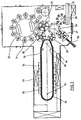
- FIG. 1 The basic structure of a device for forming preforms (1) into containers (2) is shown in Fig. 1 and in Fig. 2 shown.
- the device for shaping the container (2) essentially consists of a blowing station (3) which is provided with a blow mold (4) into which a preform (1) can be inserted.
- the preform (1) can be an injection-molded part made of polyethylene terephthalate.
- the blow mold (4) consists of mold halves (5, 6) and a base part (7) which is supported by a lifting device (8) can be positioned.
- the preform (1) can be held in the area of the blowing station (3) by a transport mandrel (9) which, together with the preform (1), passes through a plurality of treatment stations within the device.
- a transport mandrel (9) which, together with the preform (1), passes through a plurality of treatment stations within the device.
- a connecting piston (10) is arranged below the transport mandrel (9), which supplies compressed air to the preform (1) and at the same time provides a seal relative to the transport mandrel (9).
- a connecting piston (10) is arranged below the transport mandrel (9), which supplies compressed air to the preform (1) and at the same time provides a seal relative to the transport mandrel (9).
- the preform (1) is stretched with the aid of a stretching rod (11) which is positioned by a cylinder (12).
- the stretching rod (11) is mechanically positioned by means of curved segments which are acted on by pick-up rollers. The use of curve segments is particularly useful when a plurality of blowing stations (3) are arranged on a rotating blowing wheel
- the stretching system is designed such that a tandem arrangement of two cylinders (12) is provided.
- the stretching rod (11) is first moved by a primary cylinder (13) into the area of a base (14) of the preform (1) before the actual stretching process begins.
- the primary cylinder (13) with the stretching rod extended is positioned together with a carriage (15) carrying the primary cylinder (13) by a secondary cylinder (16) or via a cam control.
- the idea is to use the secondary cylinder (16) in a cam-controlled manner in such a way that a current stretching position is specified by a guide roller (17) which slides along a curved path during the stretching process.
- the guide roller (17) is pressed against the guide track by the secondary cylinder (16).
- the carriage (15) slides along two guide elements (18).
- the carriers (19, 20) are locked relative to one another with the aid of a locking device (20).
- FIG Fig. 2 To adapt to different shapes of a mouth section (21) of the preform (1) is according to FIG Fig. 2 the use of separate threaded inserts (22) in the area of the blow mold (4) is provided.
- Fig. 2 shows in addition to the blown container (2) also drawn in dashed lines the preform (1) and schematically a developing container bubble (23).
- Fig. 3 shows the basic structure of a blow molding machine that is provided with a heating section (24) and a rotating blow wheel (25).
- a preform input (26) the preforms (1) are transported by transfer wheels (27, 28, 29) into the area of the heating section (24).
- Heating element (30) and blower (31) are arranged along heating section (24) in order to control the temperature of preforms (1).
- the preforms (1) After the preforms (1) have been sufficiently heated, they are transferred to the blow wheel (25), in the area of which the blow stations (3) are arranged.
- the fully blown containers (2) are fed to an output section (32) by further transfer wheels.
- thermoplastic material can be used as thermoplastic material.
- PET PET, PEN or PP can be used.
- the preform (1) is expanded during the orientation process by supplying compressed air.
- the compressed air supply is divided into a pre-blowing phase, in which gas, for example compressed air, is supplied at a low pressure level, and is divided into a subsequent main blowing phase, in which gas is supplied at a higher pressure level.
- gas for example compressed air
- main blowing phase in which gas is supplied at a higher pressure level.
- compressed air is typically used with a pressure in the range from 10 bar to 25 bar and during the main blowing phase, compressed air is supplied with a pressure in the range from 25 bar to 40 bar.
- the heating section (24) is formed from a plurality of revolving transport elements (33) which are lined up in a chain-like manner and are guided along deflection wheels (34).
- deflection wheels (34) In particular, it is envisaged that the chain-like arrangement will create an essentially rectangular basic contour.
- a single, relatively large deflection wheel (34) is used in the area of the extension of the heating path (24) facing the transfer wheel (29) and an input wheel (35) and two comparatively smaller deflection wheels (36) are used in the area of adjacent deflections .
- any other guides are also conceivable.
- the arrangement shown proves to be particularly expedient, since three deflection wheels (34, 36) are positioned in the area of the corresponding expansion of the heating path (24), and the smaller deflection wheels (36) in the area of the transition to the linear courses of the heating section (24) and the larger deflection wheel (34) in the immediate transfer area to the transfer wheel (29) and to the input wheel (35).
- chain-like transport elements (33) it is also possible, for example, to use a rotating heating wheel.
- the containers (2) After the containers (2) have been blown, they are removed from the area of the blowing stations (3) by a removal wheel (37) and transported to the output section (32) via the transfer wheel (28) and an output wheel (38).
- the modified heating section (24) shown here can be used to control a larger number of preforms (1) per unit of time due to the larger number of heating elements (30).
- the fans (31) feed cooling air into the area of cooling air ducts (39) which are opposite the associated heating elements (30) and release the cooling air via outflow openings.
- the arrangement of the outflow directions realizes a flow direction for the cooling air essentially transversely to a transport direction of the preforms (1).
- the cooling air ducts (39) can provide reflectors for the heating radiation in the area of the surfaces opposite the heating elements (30); it is also possible to use the emitted cooling air to cool the heating elements (30).
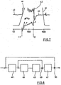
- Fig. 5 shows in a schematic representation the assignment of a mold half (5) and a container bladder (23).
- the container bubble (23) develops during the blowing process in the direction of a longitudinal axis (41) of the container and transversely to the longitudinal axis (41) of the container.
- the container bubble (23) rests against the inner wall of the blow mold (4).
- the system typically begins in an area of the blow mold (4) facing the mouth section (21) of the container (2) and then proceeds in the direction of the bottom part (7).
- Fig. 5 illustrates the progress of the application of the container bladder (23) to the blow mold (4) at different times.
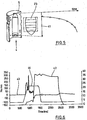
- Fig. 6 illustrates in a diagram the assignment of a temporal blow pressure curve (42), a stretching force development (43) and a stretching rod positioning (44).
- the time axis is scaled in milliseconds and the amplitude values are scaled in bar, newtons or millimeters.
- Fig. 6 illustrates that, with regard to the positioning of the stretching rod (11), it is initially retracted into the preform (1) essentially without developing a stretching force.
- the stretching rod (11) After the stretching rod (11) has come into contact with the bottom of the preform (1), the preform (1) is stretched and the stretching force is comparatively large.
- the remaining stretching force results from the stabilization of the preform in the stretched position, taking into account elastic restoring forces within the material of the preform.
- the blowing pressure curve (42) shows the division into a pre-blowing phase while the stretching process is being carried out and a main blowing phase after the stretching process has been substantially completed.
- the contact between the container bubble (23) and the blow mold (4) can be detected, for example, using touch-sensitive sensors. Contactless detection is also possible, for example via an electrical field measurement or via optical sensors. Additional measurement information is provided by recording the pressure profile, the volume of gas supplied to the container bladder (23), the stretching speed, the stretching force or the temperature in the material of the preform to be reshaped. One or more of the above can be selected Parameters are evaluated.
- the metrological detection of the above-mentioned parameters also includes an indirect determination of the above parameters by the metrological detection of an auxiliary parameter that can be assigned to the above parameters and a corresponding conversion.
- the parameters measured or determined on the basis of measurements which characterize the development of the container bladder (23), are fed to a control model and evaluated here in a suitable manner to generate manipulated variables.
- a stretching system is preferably used in which the stretching speed and / or the stretching rod positioning and / or the stretching force can be controlled or regulated.
- stretching systems with ball screw spindles, regulated pneumatic stretching systems or stretching systems based on electric linear motors or servomotors can be used.
- the development speed of the container bladder (23) is too low, it is possible to reduce the stretching speed and thereby to realize a predetermined temporal association of transverse and longitudinal stretching.
- the position of the stretching rod (11) is measured and the blowing pressure supply is controlled. This can be done using a proportional valve, for example. According to another embodiment, it is not the blowing pressure but the volume of blowing air supplied to the developing container bubble (23) that is specified.
- the stretching force is measured. If the stretching force decreases at a given stretching speed, it can be concluded from this that the container bladder (23) is developing too quickly and that the longitudinal stretching is at least only partly due to the stretching rod (11) and at least partly due to the internal pressure in the container bladder (23) ) he follows. If such a state is recognized, the volume of blowing gas supplied per unit of time can be reduced. Conversely, if the stretching force increases, which can be attributed to an insufficient development speed of the container bubble (23), the influx of blowing gas can be increased.
- control model already mentioned above comprises a multi-dimensional parameter space of setpoint values. As long as the resulting actual values lie within a corresponding multi-dimensional target area, it can be concluded that the process is optimally managed. If at least one of the parameters in question leaves the setpoint range, at least one of the available manipulated variables must be corrected.
- Fig. 7 For the pre-blowing phase, which lies between the times t1 and t2, illustrates possible variations in the rate of pressure increase by means of suitable manipulated variable variations.
- the interval between t1 and t2 typically has a duration of 50 to 100 milliseconds.
- the bubble development is influenced by the two illustrated variants of the gradient of the blowing pressure curve (42) during the implementation of the first phase of the stretching process or after a first pressure build-up.
- Fig. 8 shows schematically and in a greatly simplified embodiment a possible control circuit for influencing the development of the container bubble (23).
- there is a two-loop cascade control In an inner control loop, a volume (45) of the container bladder (23) is taken into account, which is influenced by a blowing gas supply (46).
- the molding system (47) of the container bladder (23) is taken into account, which is also influenced by the stretching system (48).
- the actual control system is much more complex due to the complex and in part non-linear relationships between the individual control and manipulated variables.
- the above-mentioned measured variables can be detected, for example, using a flow sensor (49), the measured value of which is converted into the resulting volume, and the molding system can be detected using a position sensor (50).
Landscapes
- Engineering & Computer Science (AREA)
- Manufacturing & Machinery (AREA)
- Mechanical Engineering (AREA)
- Blow-Moulding Or Thermoforming Of Plastics Or The Like (AREA)
Description
- Die Erfindung betrifft ein Verfahren zur Blasformung von Behältern, bei dem ein Vorformling aus einem thermoplastischen Material nach einer thermischen Konditionierung entlang eines Transportweges im Bereich einer Heizstrecke innerhalb einer Blasform durch Blasdruckeinwirkung in den Behälter umgeformt wird.
- Die Erfindung betrifft darüber hinaus eine Vorrichtung zur Blas-formung von Behältern aus einem thermoplastischen Material, die mindestens eine entlang eines Transportweges eines Vorformlings angeordnete Heizstrecke und eine mit einer Blasform versehene Blasstation aufweist.
- Bei einer Behälterformung durch Blasdruckeinwirkung werden Vorformlinge aus einem thermoplastischen Material, beispielsweise Vorformlinge aus PET (Polyethylenterephthalat), innerhalb einer Blasmaschine unterschiedlichen Bearbeitungsstationen zugeführt. Typischerweise weist eine derartige Blasmaschine eine Heizeinrichtung sowie eine Blaseinrichtung auf, in deren Bereich der zuvor temperierte Vorformling durch biaxiale Orientierung zu einem Behälter expandiert wird. Die Expansion erfolgt mit Hilfe von Druckluft, die in den zu expandierenden Vorformling eingeleitet wird. Der verfahrenstechnische Ablauf bei einer derartigen Expansion des Vorformlings wird in der
DE-OS 43 40 291 - Der grundsätzliche Aufbau einer Blasstation zur Behälterformung wird in der
DE-OS 42 12 583 DE-OS 23 52 926 - Innerhalb der Vorrichtung zur Blasformung können die Vorformlinge sowie die geblasenen Behälter mit Hilfe unterschiedlicher Handhabungseinrichtungen transportiert werden. Bewährt hat sich insbesondere die Verwendung von Transportdornen, auf die die Vorformlinge aufgesteckt werden. Die Vorformlinge können aber auch mit anderen Trageinrichtungen gehandhabt werden. Die Verwendung von Greifzangen zur Handhabung von Vorformlingen und die Verwendung von Spreizdornen, die zur Halterung in einen Mündungsbereich des Vorformlings einführbar sind, gehören ebenfalls zu den verfügbaren Konstruktionen.
- Eine Handhabung von Behältern unter Verwendung von Übergaberädern wird beispielsweise in der
DE-OS 199 06 438 - Die bereits erläuterte Handhabung der Vorformlinge erfolgt zum einen bei den sogenannten Zweistufenverfahren, bei denen die Vorformlinge zunächst in einem Spritzgußverfahren hergestellt, anschließend zwischengelagert und erst später hinsichtlich ihrer Temperatur konditioniert und zu einem Behälter aufgeblasen werden. Zum anderen erfolgt eine Anwendung bei den sogenannten Einstufenverfahren, bei denen die Vorformlinge unmittelbar nach ihrer spritzgußtechnischen Herstellung und einer ausreichenden Verfestigung geeignet temperiert und anschließend aufgeblasen werden.
- Im Hinblick auf die verwendeten Blasstationen sind unterschiedliche Ausführungsformen bekannt. Bei Blasstationen, die auf rotierenden Transporträdern angeordnet sind, ist eine buchartige Aufklappbarkeit der Formträger häufig anzutreffen. Es ist aber auch möglich, relativ zueinander verschiebliche oder andersartig geführte Formträger einzusetzen. Bei ortsfesten Blasstationen, die insbesondere dafür geeignet sind, mehrere Kavitäten zur Behälterformung aufzunehmen, werden typischerweise parallel zueinander angeordnete Platten als Formträger verwendet.
- Vor einer Durchführung der Beheizung werden die Vorformlinge typischerweise auf Transportdorne aufgesteckt, die den Vorformling entweder durch die gesamte Blasmaschine transportieren oder die lediglich im Bereich der Heizeinrichtung umlaufen. Bei einer stehenden Beheizung der Vorformlinge derart, daß die Mündungen der Vorformlinge in lotrechter Richtung nach unten orientiert sind, werden die Vorformlinge üblicherweise auf ein hülsenförmiges Halterungselement des Transportdornes aufgesteckt. Bei einer hängenden Beheizung der Vorformlinge, bei der diese mit ihren Mündungen in lotrechter Richtung nach oben orientiert sind, werden in der Regel Spreizdorne in die Mündungen der Vorformlinge eingeführt, die die Vorformlinge festklemmen.
- Bei der Durchführung einer blastechnischen Behälterformung besteht eine wesentliche Aufgabe darin, in der Behälterwandung eine vorgegebene Materialverteilung zu erreichen. Ein wesentlicher Parameter zur Vorgabe der sich ergebenden Materialverteilung stellt die Verteilung der vor der Blasformung in den Vorformlingen realisierten wärmeverteilung dar.
- Die Wärmeverteilung wird typischerweise derart realisiert, daß in einer Umfangsrichtung der Vorformlinge ein gleiches Temperaturniveau und in einer Längsrichtung der Vorformlinge ein Temperaturprofil erzeugt wird. Darüber hinaus erfolgt auch durch die Wand des Vorformlings hindurch von außen nach innen die Vorgabe eines geeigneten Temperaturprofils. Grundsätzlich ist davon auszugehen, daß Bereiche des Vorformlings mit einer geringeren Temperatur zu dickeren wandungsbereichen des geblasenen Behälters führen und daß die wärmeren Bereiche des Vorformlings bei der Durchführung der Blasverformung stärker verstreckt werden und hierdurch zu dünneren Wandungsbereichen des geblasenen Behälters führen.
- Die Temperatur im Bereich der Vorformlinge kann mit sogenannten Pyrometern gemessen werden. Eine meßtechnische Erfassung einer konkreten Wanddicke im Bereich der geblasenen Behälter kann mit sogenannten Wanddickensensoren erfolgen, die beispielsweise optisch oder unter Verwendung von Schallwellen arbeiten.
- Es zeigt sich allerdings, daß allein eine geeignete Vorgabe der Wärmeverteilung innerhalb der Vorformlinge nicht dafür ausreichend ist, optimale Materialeigenschaften im geblasenen Behälter zu erzeugen. Es liegen vielmehr vergleichsweise komplexe Wechselwirkungen zwischen der Durchführung des Reckvorganges, dem Druckaufbau innerhalb der sich entwickelnden Behälterblase der Materialverteilung im Vorformling und der Temperaturverteilung im Vorformling vor.
- Aus der
US 2005/194705 A1 ist es bekannt, Prozeßparameter des Blasvorganges, beispielsweise den Versorgungsdruck des Blasgases oder die Temperatur der Blasform zu messen und zu regeln. - In der
WO 03/078136 A - Die
WO 2006/108380 beschreibt die Regelung eines elektrischen Linearantriebes zur Durchführung eines Reckvorganges. Es wird allerdings nicht die konkrete Reckung des Vorformlings, sondern lediglich die Position der Reckstange geregelt. -
US 6,576,171 B1 offenbart ein Verfahren gemäß dem Oberbegriff des Anspruchs 1 sowie eine Vorrichtung gemäß dem Oberbegriff des Anspruchs 20. - Aufgabe der vorliegenden Erfindung ist es, ein Verfahren der einleitend genannten Art derart zu verbessern, daß mit geringem maschinenbaulichen Aufwand eine qualitativ hochwertige Blasformung bei gleichzeitig hohen Durchsatzraten unterstützt wird.
- Diese Aufgabe wird mit den Merkmalen der Ansprüche 1 und 20 gelöst.
- WeitereAufgabeder vorliegenden Erfindung ist es, eine Vorrichtung der einleitend genannten Art derart zu konstruieren, daß hohe Durchsatzraten bei einfachem konstruktiven Aufbau und guter Produktqualität unterstützt werden.
- Diese Aufgabe wird erfindungsgemäß dadurch gelöst, daß mindestens ein Sensor zur Erfassung mindestens eines die Umformung einer sich entwickelnden Behälterblase beim Umformen des Vorformlings in den Behälter charakterisierenden Parameters an eine Steuereinrichtung angeschlossen ist, die eine Auswertungseinheit für diesen Parameter aufweist und die mindestens eine den Umformungsvorgang beeinflussende Stellgröße generiert und die in einem geschlossenen Regelkreis zur Anpassung des gemessenen Parameters an einen zugehörigen Sollwert angeordnet ist, wobei ein Anliegen einer sich entwickelnden Behälterblase an eine Innenseite der Blasform mindestens zeitweise und mindestens abschnittweise gemessen wird.
- Erfindungsgemäß wurde erkannt, daß eine äußerst vorteilhafte Verfahrensdurchführung dadurch erreicht werden kann, daß nicht erst der fertig geblasene Behälter vermessen wird, sondern daß bereits innerhalb der Blasform die Entwicklung der Behälterblase überwacht wird, die bei der Umformung des Vorformlings in den Behälter entsteht. Durch die Auswertung der Entwicklung der Behälterblase und durch eine direkte Beeinflussung der diese Entwicklung beeinflussenden Parameter können die Materialeigenschaften des geblasenen Behälters wesentlich präziser und effektiver gesteuert und an gewünschte Eigenschaften angeglichen werden.
- Die Erfassung eines weiteren die Blasenentwicklung kennzeichnenden Parameters ist dadurch möglich, daß eine Position der Reckstange gemessen wird.
- Ebenfalls ist daran gedacht, daß eine Geschwindigkeit der Reckstange gemessen wird.
- Eine weitere Variante besteht darin, daß eine Reckkraft gemessen wird.
- Darüber hinaus ist es auch möglich, daß ein Blasdruck gemessen wird.
- Weiterhin ist es auch möglich, daß ein Blasgasvolumen gemessen wird.
- Eine definierte Einhaltung einer vorgegebenen Entwicklung der Behälterblase kann insbesondere dadurch erreicht werden, daß der Parameter entsprechend einem zeitlich veränderlichen Sollwertprofil geregelt wird.
- Generell erweist es sich als zweckmäßig, daß die Anlage der Behälterblase an der Blasform geregelt wird.
- Gemäß einer Ausführungsvariante ist vorgesehen, daß die Position der Reckstange geregelt wird.
- Ebenfalls ist daran gedacht, daß die Geschwindigkeit der Reckstange geregelt wird.
- Darüber hinaus ist es auch möglich, daß die Reckkraft geregelt wird.
- Eine weitere Ausführungsvariante besteht darin, daß der Blasdruck geregelt wird.
- Schließlich ist es auch möglich, daß das Blasgasvolumen geregelt wird.
- Eine Beeinflussung der Blasenentwicklung kann dadurch erfolgen, daß als Stellgröße die Reckgeschwindigkeit verwendet wird.
- Eine andere Ausführungsform besteht darin, daß als Stellgröße die Reckstangenposition verwendet wird.
- Darüber hinaus ist daran gedacht, daß als Stellgröße die Reckkraft verwendet wird.
- Gleichfalls ist es möglich, daß als Stellgröße der Blasdruck verwendet wird.
- Schließlich ist es ebenfalls möglich, daß als Stellgröße das Blasgasvolumen verwendet wird.
- Eine Berücksichtigung der komplexen Zusammenhänge und gegenseitigen Beeinflussungen der Einzelfaktoren kann dadurch erfolgen, daß der Meßwert einem regelungstechnischen Model zugeführt wird, das die Stellgröße generiert.
- In den Zeichnungen sind Ausführungsbeispiele der Erfindung schematisch dargestellt. Es zeigen:
- Fig. 1
- Eine perspektivische Darstellung einer Blasstation zur Herstellung von Behältern aus Vorformlingen,
- Fig. 2
- einen Längsschnitt durch eine Blasform, in der ein Vorformling gereckt und expandiert wird,
- Fig. 3
- eine Skizze zur Veranschaulichung eines grundsätzlichen Aufbaus einer Vorrichtung zur Blasformung von Behältern,
- Fig. 4
- eine modifizierte Heizstrecke mit vergrößerter Heizkapazität,
- Fig. 5
- eine schematische Darstellung zur Veranschaulichung des zeitlichen Verlaufes der Anlage der Behälterblase an der Innenwandung der Blasform,
- Fig. 6
- Diagramme zur Veranschaulichung der Zusammenhänge zwischen dem zeitlichen Druckverlauf innerhalb des Vorformlings, der Behälterblase und des geblasenen Behälters, der Reckkraftentwicklung sowie der Reckstangenpositionierung,
- Fig. 7
- eine vergrößerte teilweise Darstellung des Verlaufes gemäß
Fig. 6 mit zusätzlichen Bezugslinien und - Fig. 8
- eine schematische Darstellung eines Regelungskonzepts zur Regelung der Entwicklung der Behälterblase.
- Der prinzipielle Aufbau einer Vorrichtung zur Umformung von Vorformlingen (1) in Behälter (2) ist in
Fig. 1 und inFig. 2 dargestellt. - Die Vorrichtung zur Formung des Behälters (2) besteht im wesentlichen aus einer Blasstation (3), die mit einer Blasform (4) versehen ist, in die ein Vorformling (1) einsetzbar ist. Der Vorformling (1) kann ein spritzgegossenes Teil aus Polyethylenterephthalat sein. Zur Ermöglichung eines Einsetzens des Vorformlings (1) in die Blasform (4) und zur Ermöglichung eines Herausnehmens des fertigen Behälters (2) besteht die Blasform (4) aus Formhälften (5, 6) und einem Bodenteil (7), das von einer Hubvorrichtung (8) positionierbar ist. Der Vorformling (1) kann im Bereich der Blasstation (3) von einem Transportdorn (9) gehalten sein, der gemeinsam mit dem Vorformling (1) eine Mehrzahl von Behandlungsstationen innerhalb der Vorrichtung durchläuft. Es ist aber auch möglich, den Vorformling (1) beispielsweise über Zangen oder andere Handhabungsmittel direkt in die Blasform (4) einzusetzen.
- Zur Ermöglichung einer Druckluftzuleitung ist unterhalab des Transportdornes (9) ein Anschlußkolben (10) angeordnet, der dem Vorformling (1) Druckluft zuführt und gleichzeitig eine Aabdichtung relativ zum Transportdorn (9) vornimmt. Bei einer abgewandelten Konstruktion ist es grundsätzlich aber auch denkbar, feste Druckluftzuleitungen zu verwenden.
- Eine Reckung des Vorformlings (1) erfolgt bei diesem Ausführungsbeispiel mit Hilfe einer Reckstange (11), die von einem Zylinder (12) positioniert wird. Gemäß einer anderen Ausführungsform wird eine mechanische Positionierung der Reckstange (11) über Kurvensegmente durchgeführt, die von Abgriffrollen beaufschlagt sind. Die Verwendung von Kurvensegmenten ist insbesondere dann zweckmäßig, wenn eine Mehrzahl von Blasstationen (3) auf einem rotierenden Blasrad angeordnet sind
- Bei der in
Fig. 1 dargestellten Ausführungsform ist das Recksystem derart ausgebildet, daß eine Tandem-Anordnung von zwei Zylindern (12) bereitgestellt ist. Von einem Primärzylinder (13) wird die Reckstange (11) zunächst vor Beginn des eigentlichen Reckvorganges bis in den Bereich eines Bodens (14) des Vorformlings (1) gefahren. Während des eigentlichen Reckvorganges wird der Primärzylinder (13) mit ausgefahrener Reckstange gemeinsam mit einem den Primärzylinder (13) tragenden Schlitten (15) von einem Sekundärzylinder (16) oder über eine Kurvensteuerung positioniert. Insbesondere ist daran gedacht, den Sekundärzylinder (16) derart kurvengesteuert einzusetzen, daß von einer Führungsrolle (17), die während der Durchführung des Reckvorganges an einer Kurvenbahn entlang gleitet, eine aktuelle Reckposition vorgegeben wird. Die Führungsrolle (17) wird vom Sekundärzylinder (16) gegen die Führungsbahn gedrückt. Der Schlitten (15) gleitet entlang von zwei Führungselementen (18). - Nach einem Schließen der im Bereich von Trägern (19, 20) angeordneten Formhälften (5, 6) erfolgt eine Verriegelung der Träger (19, 20) relativ zueinander mit Hilfe einer Verriegelungseinrichtung (20).
- Zur Anpassung an unterschiedliche Formen eines Mündungsabschnittes (21) des Vorformlings (1) ist gemäß
Fig. 2 die Verwendung separater Gewindeeinsätze (22) im Bereich der Blasform (4) vorgesehen. -
Fig. 2 zeigt zusätzlich zum geblasenen Behälter (2) auch gestrichelt eingezeichnet den Vorformling (1) und schematisch eine sich entwickelnde Behälterblase (23). -
Fig. 3 zeigt den grundsätzlichen Aufbau einer Blasmaschine, die mit einer Heizstrecke (24) sowie einem rotierenden Blasrad (25) versehen ist. Ausgehend von einer Vorformlingseingabe (26) werden die Vorformlinge (1) von Übergaberädern (27, 28, 29) in den Bereich der Heizstrecke (24) transportiert. Entlang der Heizstrecke (24) sind Heizelement (30) sowie Gebläse (31) angeordnet, um die Vorformlinge (1) zu temperieren. Nach einer ausreichenden Temperierung der Vorformlinge (1) werden diese an das Blasrad (25) übergeben, in dessen Bereich die Blasstationen (3) angeordnet sind. Die fertig geblasenen Behälter (2) werden von weiteren Übergaberädern einer Ausgabestrecke (32) zugeführt. - Um einen Vorformling (1) derart in einen Behälter (2) umformen zu können, daß der Behälter (2) Materialeigenschaften aufweist, die eine lange Verwendungsfähigkeit von innerhalb des Behälters (2) abgefüllten Lebensmitteln, insbesondere von Getränken, gewährleisten, müssen spezielle Verfahrensschritte bei der Beheizung und Orientierung der Vorformlinge (1) eingehalten werden. Darüber hinaus können vorteilhafte Wirkungen durch Einhaltung spezieller Dimensionierungsvorschriften erzielt werden.
- Als thermoplastisches Material können unterschiedliche Kunststoffe verwendet werden. Einsatzfähig sind beispielsweise PET, PEN oder PP.
- Die Expansion des Vorformlings (1) während des Orientierungsvorganges erfolgt durch Druckluftzuführung. Die Druckluftzuführung ist in eine Vorblasphase, in der Gas, zum Beispiel Preßluft, mit einem niedrigen Druckniveau zugeführt wird und in eine sich anschließende Hauptblasphase unterteilt, in der Gas mit einem höheren Druckniveau zugeführt wird. Während der Vorblasphase wird typischerweise Druckluft mit einem Druck im Intervall von 10 bar bis 25 bar verwendet und während der Hauptblasphase wird Druckluft mit einem Druck im Intervall von 25 bar bis 40 bar zugeführt.
- Aus
Fig. 3 ist ebenfalls erkennbar, daß bei der dargestellten Ausführungsform die Heizstrecke (24) aus einer Vielzahl umlaufender Transportelemente (33) ausgebildet ist, die kettenartig aneinandergereiht und entlang von Umlenkrädern (34) geführt sind. Insbesondere ist daran gedacht, durch die kettenartige Anordnung eine im wesentlichen rechteckförmige Grundkontur aufzuspannen. Bei der dargestellten Ausführungsform werden im Bereich der dem Übergaberad (29) und einem Eingaberad (35) zugewandten Ausdehnung der Heizstrecke (24) ein einzelnes relativ groß dimensioniertes Umlenkrad (34) und im Bereich von benachbarten Umlenkungen zwei vergleichsweise kleiner dimensionierte Umlenkräder (36) verwendet. Grundsätzlich sind aber auch beliebige andere Führungen denkbar. - Zur Ermöglichung einer möglichst dichten Anordnung des Übergaberades (29) und des Eingaberades (35) relativ zueinander erweist sich die dargestellte Anordnung als besonders zweckmäßig, da im Bereich der entsprechenden Ausdehnung der Heizstrecke (24) drei Umlenkräder (34, 36) positioniert sind, und zwar jeweils die kleineren Umlenkräder (36) im Bereich der Überleitung zu den linearen Verläufen der Heizstrecke (24) und das größere Umlenkrad (34) im unmittelbaren Übergabebereich zum Übergaberad (29) und zum Eingaberad (35). Alternativ zur Verwendung von kettenartigen Transportelementen (33) ist es beispielsweise auch möglich, ein rotierendes Heizrad zu verwenden.
- Nach einem fertigen Blasen der Behälter (2) werden diese von einem Entnahmerad (37) aus dem Bereich der Blasstationen (3) herausgeführt und über das Übergaberad (28) und ein Ausgaberad (38) zur Ausgabestrecke (32) transportiert.
- In der in
Fig. 4 dargestellten modifizierten Heizstrecke (24) können durch die größere Anzahl von Heizelementen (30) eine größere Menge von Vorformlingen (1) je Zeiteinheit temperiert werden. Die Gebläse (31) leiten hier Kühlluft in den Bereich von Kühlluftkanälen (39) ein, die den zugeordneten Heizelementen (30) jeweils gegenüberliegen und über Ausströmöffnungen die Kühlluft abgeben. Durch die Anordnung der Ausströmrichtungen wird eine Strömungsrichtung für die Kühlluft im wesentlichen quer zu einer Transportrichtung der Vorformlinge (1) realisiert. Die Kühlluftkanäle (39) können im Bereich von den Heizelementen (30) gegenüberliegenden Oberflächen Reflektoren für die Heizstrahlung bereitstellen, ebenfalls ist es möglich, über die abgegebene Kühlluft auch eine Kühlung der Heizelemente (30) zu realisieren. -
Fig. 5 zeigt in einer schematischen Darstellung die Zuordnung einer Formhälfte (5) und einer Behälterblase (23). Die Behälterblase (23) entwickelt sich während des Blasvorganges in Richtung einer Behälterlängsachse (41) sowie quer zur Behälterlängsachse (41). Als Folge der Expansion der Behälterblase (23) quer zur Behälterlängsachse (41) legt sich die Behälterblase (23) an die Innenwand der Blasform (4) an. Die Anlage beginnt typischerweise in einem dem Mündungsabschnitt (21) des Behälters (2) zugewandten Bereich der Blasform (4) und schreitet dann in Richtung auf das Bodenteil (7) fort.Fig. 5 veranschaulicht zu verschiedenen Zeitpunkten den Fortschritt der Anlage der Behälterblase (23) an der Blasform (4). -
Fig. 6 veranschaulicht in einem Diagram die Zuordnung eines zeitlichen Blasdruckverlaufes (42), einer Reckkraftentwicklung (43) sowie einer Reckstangenpositionierung (44). Die Skalierung der zeitachse erfolgt hierbei in Millisekunden und die Amplitudenwerte sind in Bar, Newton bzw. Millimeter skaliert. -
Fig. 6 veranschaulicht, daß hinsichtlich der Positionierung der Reckstange (11) diese zunächst im wesentlichen ohne Entwicklung einer Reckkraft in den Vorformling (1) eingefahren wind. Nach einer Anlage der Reckstange (11) am Boden des Vorformlings (1) wird dieser gereckt und es erfolgt eine vergleichsweise große Entfaltung der Reckkraft. Nach einer Beendigung der Längsreckung resultiert die verbleibende Reckkraft aus der Stabilisierung des Vorformlings in der gereckten Positionierung unter Berücksichtigung von elastischen Rückstellkräften innerhalb des Materials des Vorformlings. Der Blasdruckverlauf (42) zeigt die Unterteilung in eine Vorblasphase während der Durchführung des Reckvorganges und in eine Hauptblasphase nach einem wesentlichen Abschluß des Reckvorganges. - Die Anlage der Behälterblase (23) an der Blasform (4) kann beispielsweise unter Verwendung von berührungssensitiven Sensoren erfaßt werden. Ebenfalls ist eine berührungslose Detektion beispielsweise über eine elektrische Feldmessung oder über optische Sensoren möglich. Zusätzliche Meßinformationen werden durch die Erfassung des Druckverlaufes, des der Behälterblase (23) zugeführten Gasvolumens, der Reckgeschwindigkeit, der Reckkraft oder der Temperatur im Material des umzuformenden Vorformlings bereitgestellt. Es können wahlweise ein oder mehrere der oben aufgeführten Parameter ausgewertet werden. Die meßtechnische Erfassung der oben erwähnten Parameter beinhaltet ebenfalls eine indirekte Ermittlung der obigen Parameter durch die meßtechnische Erfassung eines den obigen Parametern zuordbaren Hilfsparameters und eine entsprechende Umrechnung.
- Unter Verwendung der bereitgestellten Meßinformationen ist es insbesondere möglich, die dem Material während der Blasverformung zugeführte Umformungsarbeit bzw. Umformungsenergie zu ermitteln.
- Gemäß einer bevorzugten Ausführungsform werden die gemessenen oder aufgrund von Messungen ermittelten Parameter, die die Entwicklung der Behälterblase (23) charakterisieren, einem regelungstechnischen Model zugeführt und hier in geeigneter Art und weise zur Generierung von Stellgrößen ausgewertet. Vorzugsweise wird ein Recksystem verwendet, bei dem die Reckgeschwindigkeit und/oder die Reckstangenpositionierung und/oder die Reckkraft steuerbar bzw. regelbar sind. Verwendbar sind beispielsweise Recksysteme mit Kugelgewindespindeln, geregelte pneumatische Recksysteme oder Recksystem auf Basis von elektrischen Linearmotoren oder Servomotoren.
- Gemäß einem Ausführungsbeispiel ist es möglich, die Geschwindigkeit der Blasenentwicklung zu erfassen und beispielsweise bei einer zu schnellen Blasenentwicklung die Geschwindigkeit des Reckvorganges zu erhöhen, damit die Reckstangenpositionierung der Blasenentwicklung folgen kann und hierdurch eine Führung und Zentrierung der sich entwickelnden Behälterblase (23) durch die Reckstange (11) gewährleistet ist.
- Gemäß einer anderen Ausführungsform ist es möglich, bei einer zu geringen Entwicklungsgeschwindigkeit der Behälterblase (23) die Reckgeschwindigkeit zu vermindern und hiedurch eine vorgegebene zeitliche Zuordnung von Quer- und Längsreckung zu realisieren.
- Gemäß einer weiteren Ausführungsform wird die Position der Reckstange (11) gemessen und die Blasdruckzufuhr gesteuert. Dies kann beispielsweise unter Verwendung eines Proportionalventiles erfolgen. Gemäß einem anderen Ausführungsbeispiel wird nicht der Blasdruck, sondern das der sich entwickelnden Behälterblase (23) zugeführte Volumen an Blasluft vorgegeben.
- Gemäß einem anderen Ausführungsbeispiel wird die Reckkraft gemessen. Vermindert sich die Recckraft bei einer vorgegebenen Reckgeschwindigkeit, so kann hieraus geschlossen werden, daß eine zu schnelle Entwicklung der Behälterblase (23) vorliegt und die Längsreckung zumindest nur noch teilweise durch die Reckstange (11) und zumindest teilweise durch den Innendruck in der Behälterblase (23) erfolgt. Bei einem Erkennen eines derartigen Zustandes kann das pro Zeiteinheit zugeführte Volumen an Blasgas reduziert werden. Umgekehrt kann bei einem Anstieg der Reckkraft, die auf eine zu geringe Entwicklungsgeschwindigkeit der Behälterblase (23) zurückzuführen ist, der Zustrom an Blasgas erhöht werden.
- Gemäß einer weiteren bevorzugten Ausführungsform umfaßt das vorstehend bereits erwähnte regelungstechnische Model einen mehrdimensionalen Parameterraum von Sollwerten. So lange die sich ergebenden Istwerte innerhalb eines entsprechenden mehrdimensionalen Zielraumes liegen, kann auf eine optimale Prozeßführung geschlossen werden. Verläßt mindestens einer der betreffenden Parameter den Sollwertraum, ist eine Korrektur mindestens einer der zu Verfügung stehenden Stellgrößen erforderlich.
-
Fig. 7 veranschaulicht für die Vorblasphase, die zwischen den Zeitpunkten t1 und t2 liegt, mögliche Variationen der Druckanstiegsgeschwindigkeit durch geeignete Stellgrößenvariationen. Das Intervall zwischen t1 und t2 hat typischerweise eine Dauer von 50 bis 100 Millisekunden. Die Beeinflussung der Blasenentwicklung erfolgt durch die zwei dargestellten Varianten der Steigung des Blasdruckverlaufes (42) während der Durchführung der ersten Phase des Reckvorganges bzw. nach einem ersten Druckaufbau. -
Fig. 8 zeigt schematisch und in einer stark vereinfachten Ausführungsform einen möglichen Regelungskreis zur Beeinflussung der Entwicklung der Behälterblase (23). Im dargestellten Ausführungsbeispiel liegt eine zweischleifige Kaskadenregelung vor. In einem inneren Regelkreis ist hierbei ein Volumen (45) der Behälterblase (23) berücksichtigt, das durch eine Blasgaszufuhr (46) beeinflußt wird. Im äußeren Regelkreis ist die Formanlage (47) der Behälterblase (23) berücksichtigt, die zusätzlich über das Recksystem (48) beeinflußt wird. Das tatsächliche Regelungssystem ist aufgrund der vorliegenden komplexen und zum Teil nicht linearen Zusammenhänge der einzelnen Regel- und Stellgrößen wesentlich komplexer. - Die Erfassung der oben erwähnten Meßgrößen kann beilspielsweise unter Verwendung eines Flußsensors (49) erfolgen, dessen Meßwert in das sich ergebende Volumen umgerechnet wird und die Formanlage kann unter Verwendung eines Positionssensors (50) erfaßt werden.
Claims (20)
- Verfahren zur Blasformung von Behältern (2), bei dem ein Vorformling (1) aus einem thermoplastischem Material nach einer thermischen Konditionierung entlang eines Transportweges im Bereich einer Heizstrecke (24) innerhalb einer Blasform (4) durch Blasdruckeinwirkung in den Behälter umgeformt wird, wobei während der Umformung des Vorformlings (1) in den Behälter (2) innerhalb der Blasform zur Überwachung der Entwicklung der Behälterblase mindestens ein die Umformung charakterisierender Parameter gemessen und von einer Steuereinrichtung ausgewertet wird und in Abhängigkeit von dieser Auswertung der Entwicklung der Behälterblase mindestens eine den Umformungsvorgang beeinflussende Stellgröße innerhalb eines geschlossenen Regelkreises zum Angleichen des gemessenen Parameters an einen zugehörigen Sollwert verändert wird, dadurch gekennzeichnet, daß ein Anliegen einer sich entwickelnden Behälterblase (23) an eine Innenseite der Blasform (4) mindestens zeitweise und mindestens abschnittweise gemessen wird.
- Verfahren nach Anspruch 1, dadurch gekennzeichnet, daß eine Position der Reckstange (11) gemessen wird.
- Verfahren nach einem der Ansprüche 1 oder2, dadurch gekennzeichnet, daß eine Geschwindigkeit der Reckstange (11) gemessen wird.
- Verfahren nach einem der Ansprüche 1 bis 3, dadurch gekennzeichnet, daß eine Reckkraft gemessen wird.
- Verfahren nach einem der Ansprüche 1 bis 3, dadurch gekennzeichnet, daß ein Blasdruck gemessen wird.
- Verfahren nach einem der Ansprüche 1 bis 3, dadurch gekennzeichnet, daß ein Blasgasvolumen gemessen wird.
- Verfahren nach einem der Ansprüche 1 bis 6, dadurch gekennzeichnet, daß der Parameter entsprechend einem zeitlich veränderlichen Sollwertprofil geregelt wird.
- Verfahren nach einem der Ansprüche 1 bis 7, dadurch gekennzeichnet, daß die Anlage der Behälterblase (23) an der Blasform (4) geregelt wird.
- Verfahren nach einem der Ansprüche 1 bis 8, dadurch gekennzeichnet, daß die Position der Reckstange (11) geregelt wird.
- Verfahren nach einem der Ansprüche 1 bis 8, dadurch gekennzeichnet, daß die Geschwindigkeit der Reckstange (11) geregelt wird.
- Verfahren nach einem der Ansprüche 1 bis 10, dadurch gekennzeichnet, daß die Reckkraft geregelt wird.
- Verfahren nach einem der Ansprüche 1 bis 10, dadurch gekennzeichnet, daß der Blasdruck geregelt wird.
- Verfahren nach einem der Ansprüche 1 bis 10, dadurch gekennzeichnet, daß das Blasgasvolumen geregelt wird.
- Verfahren nach einem der Ansprüche 1 bis 13, dadurch gekennzeichnet, daß als Stellgröße die Reckgeschwindigkeit verwendet wird.
- Verfahren nach einem der Ansprüche 1 bis 13, dadurch gekennzeichnet, daß als Stellgröße die Reckstangenposition verwendet wird.
- Verfahren nach einem der Ansprüche 1 bis 13, dadurch gekennzeichnet, daß als Stellgröße die Reckkraft verwendet wird.
- Verfahren nach einem der Ansprüche 1 bis 13, dadurch gekennzeichnet, daß als Stellgröße der Blasdruck verwendet wird.
- Verfahren nach einem der Ansprüche 1 bis 13, dadurch gekennzeichnet, daß als Stellgröße das Blasgasvolumen verwendet wird.
- Verfahren nach einem der Ansprüche 1 bis 18, dadurch gekennzeichnet, daß der Meßwert einem regelungstechnischen Model zugeführt wird, das die Stellgröße generiert.
- Vorrichtung zur Blasformung von Behältern (2) aus einem thermoplastischen Material, die mindestens eine entlang eines Transportweges eines Vorformlings (1) angeordnete Heizstrecke (24) und eine mit einer Blasform (4) versehene Blasstation (3) aufweist, wobei mindestens ein Sensor zur Erfassung mindestens eines die Umformung des Vorformlings (1) in den Behälter (2) charakterisierenden Parameters an eine Steuereinrichtung angeschlossen ist, die eine Auswertungseinheit für diesen Parameter aufweist und die mindestens eine den Umformungsvorgang beeinflussende Stellgröße generiert und die in einem geschlossenen Regelkreis zur Anpassung des gemessenen Parameters an einen zugehörigen Sollwert angeordnet ist, wobei der Sensor angeordnet und ausgebildet ist zur Erfassung der Entwicklung der Behälterblase innerhalb der Blasform und wobei die Steuereinrichtung zur Auswertung der Entwicklung der Behälterblase ausgebildet ist, nämlich dadurch gekennzeichnet, daß der Sensor ein Anliegen einer sich entwickelnden Behälterblase (23) an eine Innenseite der Blasform (4) mindestens zeitweise und mindestens abschnittweise messend ausgebildet ist.
Applications Claiming Priority (2)
| Application Number | Priority Date | Filing Date | Title |
|---|---|---|---|
| DE102008013419A DE102008013419A1 (de) | 2008-03-06 | 2008-03-06 | Verfahren und Vorrichtung zur Blasformung von Behältern |
| PCT/DE2009/000150 WO2009109159A1 (de) | 2008-03-06 | 2009-02-02 | Verfahren und vorrichtung zur blasformung von behältern |
Publications (3)
| Publication Number | Publication Date |
|---|---|
| EP2247429A1 EP2247429A1 (de) | 2010-11-10 |
| EP2247429B1 EP2247429B1 (de) | 2014-01-08 |
| EP2247429B2 true EP2247429B2 (de) | 2020-09-16 |
Family
ID=40723068
Family Applications (1)
| Application Number | Title | Priority Date | Filing Date |
|---|---|---|---|
| EP09716999.9A Active EP2247429B2 (de) | 2008-03-06 | 2009-02-02 | Verfahren und vorrichtung zur blasformung von behältern |
Country Status (6)
| Country | Link |
|---|---|
| US (1) | US9545748B2 (de) |
| EP (1) | EP2247429B2 (de) |
| JP (1) | JP5608564B2 (de) |
| CN (1) | CN101959668B (de) |
| DE (2) | DE102008013419A1 (de) |
| WO (1) | WO2009109159A1 (de) |
Families Citing this family (19)
| Publication number | Priority date | Publication date | Assignee | Title |
|---|---|---|---|---|
| DE102010028255A1 (de) | 2010-04-27 | 2011-10-27 | Krones Ag | Streckblasmaschine |
| DE102010021445A1 (de) * | 2010-05-25 | 2011-12-01 | Krones Ag | Verfahren und Vorrichtung zur Temperatursteuerung und/oder -regelung einer Heizvorrichtung für Vorformlinge |
| DE102010047104A1 (de) * | 2010-10-01 | 2012-04-05 | Krones Aktiengesellschaft | Vorrichtung zum Umformen von Kunststoffvorformlingen zu Kunststoffbehältnissen mit variabler Ausstoßleistung |
| IT1403124B1 (it) * | 2010-10-21 | 2013-10-04 | Siapi S R L | Procedimento ed apparecchiatura per la produzione di contenitori soffiati a doppia parete |
| EP2463079A1 (de) | 2010-12-10 | 2012-06-13 | Nestec S.A. | Verfahren zum Formen und Füllen von Behältern in einem Schritt |
| AU2012217945B2 (en) * | 2011-02-15 | 2017-05-11 | Discma Ag | Reverse stretch rod for machine hygiene and processing |
| FR2998207B1 (fr) * | 2012-11-20 | 2015-01-16 | Sidel Participations | Procede d'etirage soufflage d'un recipient, comprenant une mesure du deplacement de la tige d'etirage au cours d'une operation de boxage |
| FR3014352B1 (fr) * | 2013-12-09 | 2016-01-22 | Sidel Participations | Dispositif de traitement en serie de corps creux comportant une tige de traitement commandee en coulissement par un actionneur electrique et procede de traitement |
| FR3023503B1 (fr) * | 2014-07-11 | 2016-07-29 | Sidel Participations | Mesure de la course de boxage par la fonction etirage, dans une installation de fabrication de recipients |
| DE102016119785A1 (de) | 2016-10-18 | 2018-04-19 | Fhw-Moulds Gmbh | Extrusionsblasform |
| DE102016013635B4 (de) | 2016-11-16 | 2021-08-05 | Aventics Gmbh | Vorrichtung und Verfahren zur Steuerung des Blasfluiddurchflusses beim Blasformen von Behältern |
| DE102017120161A1 (de) | 2017-09-01 | 2019-03-07 | Krones Aktiengesellschaft | System und Verfahren zur Zustandsüberwachung von Linearantrieben von Streck- /Blasmaschinen |
| DE102017010970A1 (de) * | 2017-11-27 | 2019-05-29 | Khs Corpoplast Gmbh | Temperiervorrichtung für die Temperaturkonditionierung von Vorformlingen und Verfahren zum Betreiben einer solchen Temperiervorrichtung |
| DE102018004159A1 (de) * | 2018-05-23 | 2019-11-28 | Khs Corpoplast Gmbh | Mehrteilig ausgebildete Form für die umformende Herstellung von Behältern mit Griff, Umformstation, Umformrad und Umformmaschine mit einer solchen Form, Verfahren zur Herstellung eines Behälters mit Griff und nach diesem Verfahren hergestellter Behälter |
| CN113910579B (zh) * | 2021-11-08 | 2025-05-02 | 上海新松机器人有限公司 | 一种血管支架吹塑成型设备 |
| CN115179526A (zh) * | 2022-06-28 | 2022-10-14 | 南通鸿图健康科技有限公司 | 具有过热保护功能的塑料桶用均衡压模装置 |
| CN114986855B (zh) * | 2022-07-19 | 2022-11-01 | 广东乐善智能装备股份有限公司 | 一种吹瓶机自适应吹瓶控制方法及系统 |
| DE102022122969A1 (de) * | 2022-09-09 | 2024-03-14 | Krones Aktiengesellschaft | Vorrichtung und Verfahren zur Herstellung von Behältern |
| DE102024112652A1 (de) * | 2024-05-06 | 2025-11-06 | Khs Gmbh | Verfahren zum Erfassen des Betriebsverhaltens einer Behälterbehandlungsanlage |
Citations (3)
| Publication number | Priority date | Publication date | Assignee | Title |
|---|---|---|---|---|
| US6576171B1 (en) † | 1998-03-25 | 2003-06-10 | Tetra Laval Holdings & Finance Sa | Machine and process for moulding by stretching and blowing |
| US20070290388A1 (en) † | 2004-10-21 | 2007-12-20 | Guy Feuilloley | Method for Capacitive Measurement of One Characteristic of a Thermoplastic Container in a Mold, and Mold Equipped With Same |
| WO2008081109A2 (fr) † | 2006-12-05 | 2008-07-10 | Sidel Participations | Procede de fabrication d'un recipient a partir d'une ebauche, avec retroaction en fonction du point de fin d'expansion de l'ebauche |
Family Cites Families (78)
| Publication number | Priority date | Publication date | Assignee | Title |
|---|---|---|---|---|
| US5360329A (en) | 1957-10-22 | 1994-11-01 | Lemelson Jerome H | Molding/extrusion apparatus with temperature and flow control |
| US5264163A (en) | 1957-10-22 | 1993-11-23 | Lemelson Jerome H | Method of controlling the internal structure of matter |
| US3865530A (en) * | 1971-08-18 | 1975-02-11 | Jesselallee | Pressure control during blow-moulding |
| US3795719A (en) | 1971-09-09 | 1974-03-05 | Baychem Corp | Method of controlling the blow molding of hollow shaped plastic articles |
| DE2352926A1 (de) | 1973-10-22 | 1975-04-24 | Heidenreich & Harbeck Gmbh | Verfahren und vorrichtung zum erwaermen eines werkstueckes aus kunststoff |
| US4295811A (en) * | 1974-03-05 | 1981-10-20 | National Can Corporation | Apparatus for making multilayered containers |
| US4364721A (en) * | 1979-04-17 | 1982-12-21 | Rainville Company, Inc. | Apparatus for blowing oriented containers |
| JPS5812142B2 (ja) | 1979-08-17 | 1983-03-07 | 石川島播磨重工業株式会社 | ブロ−成形機 |
| US4484884A (en) * | 1981-04-24 | 1984-11-27 | Cincinnati Milacron Inc. | Apparatus for high rate production of biaxially oriented thermoplastic articles |
| US4437825A (en) * | 1981-11-13 | 1984-03-20 | The Continental Group, Inc. | Blow molding apparatus |
| US4409161A (en) * | 1981-11-13 | 1983-10-11 | The Continental Group, Inc. | Blow molding method |
| GB2221642A (en) | 1988-07-14 | 1990-02-14 | Harcostar Ltd | Regulating the wall thickness of an extruding parison |
| FR2638118A1 (fr) * | 1988-10-20 | 1990-04-27 | Adl Automation | Procede et appareil pour la compression et le controle de la compression de matieres pulverulentes et presse en faisant application |
| US5202068A (en) * | 1990-10-24 | 1993-04-13 | Modern Controls, Inc. | Method and apparatus for controlling blown film thickness |
| EP0499136A3 (en) | 1991-02-14 | 1993-06-23 | Husky Injection Molding Systems Ltd. | Servo electric driven stretch rods for blow molding machine |
| JP2833673B2 (ja) | 1991-04-30 | 1998-12-09 | 宇部興産株式会社 | ブロー成形機の型締制御方法および装置 |
| JPH0516136A (ja) | 1991-07-09 | 1993-01-26 | Ube Ind Ltd | パリソン長さ制御方法およびパリソン形成装置 |
| DE4212583A1 (de) | 1992-04-15 | 1993-10-21 | Krupp Corpoplast Masch | Vorrichtung zur Blasformung |
| US5269672A (en) * | 1992-06-29 | 1993-12-14 | Hoover Universal, Inc. | Servo stretch assembly for blow molding machine |
| US5419866A (en) * | 1992-11-06 | 1995-05-30 | Pepsico Inc. | Process for heat treating thermoplastic containers |
| JPH06234152A (ja) | 1993-02-10 | 1994-08-23 | Nippon Steel Chem Co Ltd | ブロー成形法および装置 |
| US5474735A (en) * | 1993-09-24 | 1995-12-12 | Continental Pet Technologies, Inc. | Pulse blow method for forming container with enhanced thermal stability |
| DE4340291A1 (de) | 1993-11-26 | 1995-06-01 | Krupp Corpoplast Masch | Mehrfachnutzung von Blasluft |
| JP3294019B2 (ja) * | 1994-09-26 | 2002-06-17 | 株式会社青木固研究所 | 大型容器の延伸吹込成形方法 |
| GB2294659B (en) | 1994-11-03 | 1998-05-06 | George Robin Enderby | Interface units for extrusion blow moulding control systems |
| JPH09174673A (ja) * | 1995-12-25 | 1997-07-08 | Mitsubishi Plastics Ind Ltd | 延伸ブロー成形機の監視装置及びその方法 |
| JPH09272147A (ja) * | 1996-04-05 | 1997-10-21 | Mitsubishi Plastics Ind Ltd | ブロー成形機のストレッチ装置 |
| DE19727278A1 (de) * | 1997-02-17 | 1999-01-07 | Kronseder Maschf Krones | Blasformmaschine |
| US5866175A (en) * | 1997-08-01 | 1999-02-02 | Latham; Greig S. | Stretch blow molding machine monitoring system |
| US6186760B1 (en) * | 1997-08-01 | 2001-02-13 | Greig S. Latham | Blow mold machine monitor and control system |
| US5939153A (en) * | 1997-11-13 | 1999-08-17 | The Elizabeth And Sandor Valyi Foundation, Inc. | Multilayered plastic container |
| DE19843053A1 (de) * | 1998-09-19 | 2000-03-23 | Krupp Corpoplast Masch | Verfahren und Vorrichtung zur Steuerung eines Blasvorganges |
| DE19906438A1 (de) | 1999-02-16 | 2000-08-17 | Krupp Corpoplast Masch | Verfahren und Vorrichtung zur Übergabe von Behältern |
| WO2001019546A1 (en) * | 1999-09-16 | 2001-03-22 | Sintokogio, Ltd. | Blow molding method for superplastic materials and system |
| ITPN20000015A1 (it) * | 2000-03-01 | 2001-09-03 | Sipa Spa | Impianto con dispositivo automatico di rilevazione di scoppio di contenitori soffiati |
| ITPN20010009A1 (it) * | 2001-02-07 | 2002-08-07 | Sipa Spa | Procedimento per la produzione di contenitori in pet con bocca fuoricentro |
| DE10116665B4 (de) | 2001-04-04 | 2015-10-29 | Krones Aktiengesellschaft | Verfahren zur Steuerung eines Blasvorgangs bei der Herstellung von Behältern aus einem thermoplastischen Material |
| DE10121160A1 (de) | 2001-04-30 | 2002-10-31 | Sig Corpoplast Gmbh & Co Kg | Verfahren und Vorrichtung zur Temperierung von Vorformlingen |
| FR2827541B1 (fr) | 2001-07-20 | 2005-07-01 | Technoplan Engineering S A | Dispositif de soufflage d'emballages |
| JP2003039533A (ja) * | 2001-07-27 | 2003-02-13 | Taisei Kako Co Ltd | ボトルのブロー成形装置、並びに、ボトルのブロー成形方法 |
| JP3415609B2 (ja) * | 2001-09-21 | 2003-06-09 | 花王株式会社 | 成形体の製造方法 |
| US6553809B1 (en) * | 2001-11-01 | 2003-04-29 | Plastic Technologies, Inc. | Method and apparatus for detecting holes in plastic containers |
| US6855289B2 (en) * | 2001-11-27 | 2005-02-15 | Graham Packaging Pet Technologies, Inc. | Method and apparatus for cooling during in-mold handle attachment |
| US20030171889A1 (en) * | 2002-03-04 | 2003-09-11 | Shelby Marcus David | Method and device for predicting temperature profiles throughout the thickness of a polymer preform |
| DE10231345A1 (de) | 2002-03-18 | 2003-10-16 | Tetra Laval Holdings & Finance | Vorrichtung zur Herstellung von Kunstoffbehältern mittels Streckblasformen und Vorrichtung zum Beschichten der Innenwände eines Kunstoffbehälters |
| US6863860B1 (en) | 2002-03-26 | 2005-03-08 | Agr International, Inc. | Method and apparatus for monitoring wall thickness of blow-molded plastic containers |
| DE10215722B4 (de) * | 2002-04-10 | 2009-11-26 | Husky Injection Molding Systems Ltd., Bolton | Verfahren und Vorrichtung zur Bearbeitung von Vorformlingen |
| FR2838839B1 (fr) * | 2002-04-19 | 2004-07-09 | Olicorp Sarl | Dispositif de regulation du debit et/ou de la pression d'un fluide |
| DE10259589B3 (de) * | 2002-12-19 | 2004-04-01 | Krones Ag | Verfahren und Vorrichtung zum Herstellen von Hohlkörpern aus Kunststoff |
| WO2005000558A1 (en) | 2003-06-10 | 2005-01-06 | Petwall, Llc | Container manufacturing inspection and control system |
| US7534378B2 (en) | 2004-03-03 | 2009-05-19 | Rexam Prescription Products Inc. | Plastic forming process monitoring and control |
| FR2869563B1 (fr) * | 2004-04-30 | 2007-09-07 | Sidel Sas | Preforme en polypropylene pour la fabrication de bouteilles ou analogues par soufflage ou etirage-soufflage et procede de soufflage ou d'etirage-soufflage de cette preforme |
| ITMO20040164A1 (it) * | 2004-06-29 | 2004-09-29 | Sacmi Cooperativa Maccanici Im | Apparati e metodi per produrre oggetti. |
| FR2878308B1 (fr) | 2004-11-19 | 2007-04-20 | Parker Lucifer Sa Sa | Dispositif a electrovanne auto controle |
| FR2881979B1 (fr) | 2005-02-17 | 2007-04-27 | Sidel Sas | Procede de commande d'une machine de soufflage de recipients visant a corriger des anomalies dans la repartition de matiere |
| US20060197263A1 (en) * | 2005-03-03 | 2006-09-07 | Graham Packaging Company, L.P. | Blow air control system |
| DE102005040905A1 (de) | 2005-04-12 | 2006-10-19 | Sig Technology Ltd. | Verfahren und Vorrichtung zur Positionierung eines Bauelementes |
| US7646567B2 (en) * | 2005-06-28 | 2010-01-12 | Seagate Technology Llc | Flex on suspension with a heat-conducting protective layer for reflowing solder interconnects |
| DE102005034846A1 (de) * | 2005-07-26 | 2007-02-01 | Sig Technology Ag | Verfahren und Vorrichtung zur Positionierung eines Bauelementes |
| US8535598B2 (en) * | 2005-08-04 | 2013-09-17 | Jsp Corporation | Method of forming hollow foam moldings |
| DE102006014389A1 (de) * | 2006-03-29 | 2007-10-25 | Sig Technology Ltd. | Verfahren und Vorrichtung zur Blasformung von Behältern |
| FR2909304B1 (fr) | 2006-12-05 | 2009-03-27 | Sidel Participations | Procede de fabrication de recipients avec retroaction en fonction du point de debut de presoufflage |
| FR2909305B1 (fr) | 2006-12-05 | 2009-03-27 | Sidel Participations | Procede de fabrication d'un recipient a partir d'une ebauche, avec retroaction en fonction du point de developpement de l'ebauche. |
| DE102006061301A1 (de) | 2006-12-22 | 2008-06-26 | Krones Ag | Verfahren zur Herstellung von Behältern |
| JP4831353B2 (ja) | 2007-02-26 | 2011-12-07 | 東洋製罐株式会社 | 空調付きブロー成形機 |
| JP5090940B2 (ja) | 2008-01-28 | 2012-12-05 | 株式会社旭製作所 | ワンタッチカプラ |
| JP5077056B2 (ja) | 2008-05-08 | 2012-11-21 | 東芝ライテック株式会社 | 照明制御システム及び照明制御方法 |
| DE102008057999A1 (de) * | 2008-11-13 | 2010-05-20 | Khs Corpoplast Gmbh & Co. Kg | Verfahren und Vorrichtung zur Blasformung von Behältern |
| US8226180B2 (en) * | 2008-12-04 | 2012-07-24 | General Electric Company | Door coupling system |
| EP2669967A1 (de) | 2008-12-22 | 2013-12-04 | E. I. du Pont de Nemours and Company | Elektronisches Gerät mit einem Phenanthrolinderivat |
| US9023446B2 (en) * | 2009-09-22 | 2015-05-05 | Graham Packaging Lc, L.P. | PET containers with enhanced thermal properties and process for making same |
| DE102010028255A1 (de) * | 2010-04-27 | 2011-10-27 | Krones Ag | Streckblasmaschine |
| DE102010021446A1 (de) * | 2010-05-25 | 2011-12-01 | Krones Ag | Verfahren und Vorrichtung zur Temperierung von Vorformlingen |
| DE102010047104A1 (de) * | 2010-10-01 | 2012-04-05 | Krones Aktiengesellschaft | Vorrichtung zum Umformen von Kunststoffvorformlingen zu Kunststoffbehältnissen mit variabler Ausstoßleistung |
| DE102011080833A1 (de) * | 2011-08-11 | 2013-02-14 | Krones Aktiengesellschaft | Vorrichtung und Verfahren zum Blasformen von Behältern |
| US9205592B2 (en) * | 2012-01-13 | 2015-12-08 | The Procter & Gamble Company | Process for the manufacture of an article comprimising a recess |
| DE102014005533B3 (de) * | 2014-04-16 | 2015-03-05 | Khs Corpoplast Gmbh | Blasstation mit druckluftbetriebener Formzuhaltung sowie Verfahren zum Zusammenhalten einer mehrteilig ausgebildeten Blasform |
| DE102014119563A1 (de) * | 2014-12-23 | 2016-06-23 | Krones Ag | Verfahren zum Umformen von Kunststoffvorformlingen |
-
2008
- 2008-03-06 DE DE102008013419A patent/DE102008013419A1/de not_active Withdrawn
-
2009
- 2009-02-02 EP EP09716999.9A patent/EP2247429B2/de active Active
- 2009-02-02 DE DE112009001063T patent/DE112009001063A5/de not_active Withdrawn
- 2009-02-02 JP JP2010549008A patent/JP5608564B2/ja active Active
- 2009-02-02 CN CN200980107938.0A patent/CN101959668B/zh active Active
- 2009-02-02 WO PCT/DE2009/000150 patent/WO2009109159A1/de not_active Ceased
- 2009-02-02 US US12/921,260 patent/US9545748B2/en active Active
Patent Citations (3)
| Publication number | Priority date | Publication date | Assignee | Title |
|---|---|---|---|---|
| US6576171B1 (en) † | 1998-03-25 | 2003-06-10 | Tetra Laval Holdings & Finance Sa | Machine and process for moulding by stretching and blowing |
| US20070290388A1 (en) † | 2004-10-21 | 2007-12-20 | Guy Feuilloley | Method for Capacitive Measurement of One Characteristic of a Thermoplastic Container in a Mold, and Mold Equipped With Same |
| WO2008081109A2 (fr) † | 2006-12-05 | 2008-07-10 | Sidel Participations | Procede de fabrication d'un recipient a partir d'une ebauche, avec retroaction en fonction du point de fin d'expansion de l'ebauche |
Also Published As
| Publication number | Publication date |
|---|---|
| DE112009001063A5 (de) | 2011-01-27 |
| EP2247429B1 (de) | 2014-01-08 |
| CN101959668B (zh) | 2014-06-11 |
| CN101959668A (zh) | 2011-01-26 |
| US9545748B2 (en) | 2017-01-17 |
| JP5608564B2 (ja) | 2014-10-15 |
| US20110037189A1 (en) | 2011-02-17 |
| EP2247429A1 (de) | 2010-11-10 |
| JP2011514271A (ja) | 2011-05-06 |
| DE102008013419A1 (de) | 2009-09-10 |
| WO2009109159A1 (de) | 2009-09-11 |
Similar Documents
| Publication | Publication Date | Title |
|---|---|---|
| EP2247429B2 (de) | Verfahren und vorrichtung zur blasformung von behältern | |
| EP2352633B1 (de) | Verfahren und Vorrichtung zur Blasformung von Behältern | |
| EP1998950B1 (de) | Verfahren und vorrichtung zur blasformung von behältern unter verwendung von wanddickenmessung des geformten gegenstandes | |
| EP2470348B1 (de) | Verfahren und vorrichtung zur blasformung von behältern | |
| EP2188108B2 (de) | Verfahren zur blasformung von behältern | |
| EP2081752B1 (de) | Verfahren und vorrichtung zur blasformung von behältern | |
| EP2504148B1 (de) | Verfahren zur blasformung von behältern | |
| EP2307185B1 (de) | Verfahren und vorrichtung zur blasformung von behältern | |
| DE19843053A1 (de) | Verfahren und Vorrichtung zur Steuerung eines Blasvorganges | |
| EP1383636A1 (de) | Verfahren und vorrichtung zur temperierung von vorformlingen | |
| DE102009021277A1 (de) | Verfahren und Vorrichtung zur Blasformung sowie zum Befüllen von Behältern | |
| EP1484160A1 (de) | Vorrichtung zur Blasformung von Behältern mit einer von linearem Motor angetriebenen Reckstange | |
| EP1868767B1 (de) | Verfahren und vorrichtung zur positionierung eines bauelements | |
| EP1910056B1 (de) | Verfahren und vorrichtung zur positionierung eines bauelementes | |
| EP2694270B1 (de) | Vorrichtung zur blasformung von behältern | |
| EP1732743B1 (de) | Verfahren und vorrichtung zur blasformung von behältern unter verwendung einer reduzierten druckanstiegsgeschwindigkeit | |
| EP2129508B1 (de) | Verfahren zur blasformung von behältern | |
| EP1566258A2 (de) | Vorrichtung zur Bearbeitung von Werkstücken | |
| EP1473139A1 (de) | Verfahren und Vorrichtung zur Blasformung von Behältern | |
| DE102006004940A1 (de) | Verfahren und Vorrichtung zur Blasformung von Behältern | |
| DE19958435A1 (de) | Verfahren und Vorrichtung zur Blasformung von Behältern | |
| DE102004050531A1 (de) | Verfahren und Vorrichtung zur Blasformung von Behältern |
Legal Events
| Date | Code | Title | Description |
|---|---|---|---|
| PUAI | Public reference made under article 153(3) epc to a published international application that has entered the european phase |
Free format text: ORIGINAL CODE: 0009012 |
|
| 17P | Request for examination filed |
Effective date: 20100727 |
|
| AK | Designated contracting states |
Kind code of ref document: A1 Designated state(s): AT BE BG CH CY CZ DE DK EE ES FI FR GB GR HR HU IE IS IT LI LT LU LV MC MK MT NL NO PL PT RO SE SI SK TR |
|
| AX | Request for extension of the european patent |
Extension state: AL BA RS |
|
| RAP1 | Party data changed (applicant data changed or rights of an application transferred) |
Owner name: KHS CORPOPLAST GMBH |
|
| DAX | Request for extension of the european patent (deleted) | ||
| 17Q | First examination report despatched |
Effective date: 20121030 |
|
| GRAP | Despatch of communication of intention to grant a patent |
Free format text: ORIGINAL CODE: EPIDOSNIGR1 |
|
| INTG | Intention to grant announced |
Effective date: 20130913 |
|
| GRAS | Grant fee paid |
Free format text: ORIGINAL CODE: EPIDOSNIGR3 |
|
| GRAA | (expected) grant |
Free format text: ORIGINAL CODE: 0009210 |
|
| AK | Designated contracting states |
Kind code of ref document: B1 Designated state(s): AT BE BG CH CY CZ DE DK EE ES FI FR GB GR HR HU IE IS IT LI LT LU LV MC MK MT NL NO PL PT RO SE SI SK TR |
|
| REG | Reference to a national code |
Ref country code: GB Ref legal event code: FG4D Free format text: NOT ENGLISH |
|
| REG | Reference to a national code |
Ref country code: CH Ref legal event code: EP |
|
| REG | Reference to a national code |
Ref country code: IE Ref legal event code: FG4D Free format text: LANGUAGE OF EP DOCUMENT: GERMAN |
|
| REG | Reference to a national code |
Ref country code: AT Ref legal event code: REF Ref document number: 648423 Country of ref document: AT Kind code of ref document: T Effective date: 20140215 |
|
| REG | Reference to a national code |
Ref country code: DE Ref legal event code: R096 Ref document number: 502009008646 Country of ref document: DE Effective date: 20140220 |
|
| REG | Reference to a national code |
Ref country code: CH Ref legal event code: NV Representative=s name: ISLER AND PEDRAZZINI AG, CH |
|
| REG | Reference to a national code |
Ref country code: NL Ref legal event code: VDEP Effective date: 20140108 |
|
| REG | Reference to a national code |
Ref country code: LT Ref legal event code: MG4D |
|
| PG25 | Lapsed in a contracting state [announced via postgrant information from national office to epo] |
Ref country code: NO Free format text: LAPSE BECAUSE OF FAILURE TO SUBMIT A TRANSLATION OF THE DESCRIPTION OR TO PAY THE FEE WITHIN THE PRESCRIBED TIME-LIMIT Effective date: 20140408 Ref country code: IS Free format text: LAPSE BECAUSE OF FAILURE TO SUBMIT A TRANSLATION OF THE DESCRIPTION OR TO PAY THE FEE WITHIN THE PRESCRIBED TIME-LIMIT Effective date: 20140508 Ref country code: LT Free format text: LAPSE BECAUSE OF FAILURE TO SUBMIT A TRANSLATION OF THE DESCRIPTION OR TO PAY THE FEE WITHIN THE PRESCRIBED TIME-LIMIT Effective date: 20140108 |
|
| PG25 | Lapsed in a contracting state [announced via postgrant information from national office to epo] |
Ref country code: SE Free format text: LAPSE BECAUSE OF FAILURE TO SUBMIT A TRANSLATION OF THE DESCRIPTION OR TO PAY THE FEE WITHIN THE PRESCRIBED TIME-LIMIT Effective date: 20140108 Ref country code: FI Free format text: LAPSE BECAUSE OF FAILURE TO SUBMIT A TRANSLATION OF THE DESCRIPTION OR TO PAY THE FEE WITHIN THE PRESCRIBED TIME-LIMIT Effective date: 20140108 Ref country code: NL Free format text: LAPSE BECAUSE OF FAILURE TO SUBMIT A TRANSLATION OF THE DESCRIPTION OR TO PAY THE FEE WITHIN THE PRESCRIBED TIME-LIMIT Effective date: 20140108 Ref country code: ES Free format text: LAPSE BECAUSE OF FAILURE TO SUBMIT A TRANSLATION OF THE DESCRIPTION OR TO PAY THE FEE WITHIN THE PRESCRIBED TIME-LIMIT Effective date: 20140108 Ref country code: CY Free format text: LAPSE BECAUSE OF FAILURE TO SUBMIT A TRANSLATION OF THE DESCRIPTION OR TO PAY THE FEE WITHIN THE PRESCRIBED TIME-LIMIT Effective date: 20140108 Ref country code: PT Free format text: LAPSE BECAUSE OF FAILURE TO SUBMIT A TRANSLATION OF THE DESCRIPTION OR TO PAY THE FEE WITHIN THE PRESCRIBED TIME-LIMIT Effective date: 20140508 |
|
| BERE | Be: lapsed |
Owner name: KHS CORPOPLAST G.M.B.H. Effective date: 20140228 |
|
| PG25 | Lapsed in a contracting state [announced via postgrant information from national office to epo] |
Ref country code: LV Free format text: LAPSE BECAUSE OF FAILURE TO SUBMIT A TRANSLATION OF THE DESCRIPTION OR TO PAY THE FEE WITHIN THE PRESCRIBED TIME-LIMIT Effective date: 20140108 Ref country code: HR Free format text: LAPSE BECAUSE OF FAILURE TO SUBMIT A TRANSLATION OF THE DESCRIPTION OR TO PAY THE FEE WITHIN THE PRESCRIBED TIME-LIMIT Effective date: 20140108 |
|
| REG | Reference to a national code |
Ref country code: DE Ref legal event code: R026 Ref document number: 502009008646 Country of ref document: DE |
|
| PLBI | Opposition filed |
Free format text: ORIGINAL CODE: 0009260 |
|
| PG25 | Lapsed in a contracting state [announced via postgrant information from national office to epo] |
Ref country code: RO Free format text: LAPSE BECAUSE OF FAILURE TO SUBMIT A TRANSLATION OF THE DESCRIPTION OR TO PAY THE FEE WITHIN THE PRESCRIBED TIME-LIMIT Effective date: 20140108 Ref country code: CZ Free format text: LAPSE BECAUSE OF FAILURE TO SUBMIT A TRANSLATION OF THE DESCRIPTION OR TO PAY THE FEE WITHIN THE PRESCRIBED TIME-LIMIT Effective date: 20140108 Ref country code: MC Free format text: LAPSE BECAUSE OF FAILURE TO SUBMIT A TRANSLATION OF THE DESCRIPTION OR TO PAY THE FEE WITHIN THE PRESCRIBED TIME-LIMIT Effective date: 20140108 Ref country code: EE Free format text: LAPSE BECAUSE OF FAILURE TO SUBMIT A TRANSLATION OF THE DESCRIPTION OR TO PAY THE FEE WITHIN THE PRESCRIBED TIME-LIMIT Effective date: 20140108 Ref country code: DK Free format text: LAPSE BECAUSE OF FAILURE TO SUBMIT A TRANSLATION OF THE DESCRIPTION OR TO PAY THE FEE WITHIN THE PRESCRIBED TIME-LIMIT Effective date: 20140108 |
|
| 26 | Opposition filed |
Opponent name: SIDEL PARTICIPATIONS Effective date: 20141008 |
|
| PLAX | Notice of opposition and request to file observation + time limit sent |
Free format text: ORIGINAL CODE: EPIDOSNOBS2 |
|
| PG25 | Lapsed in a contracting state [announced via postgrant information from national office to epo] |
Ref country code: PL Free format text: LAPSE BECAUSE OF FAILURE TO SUBMIT A TRANSLATION OF THE DESCRIPTION OR TO PAY THE FEE WITHIN THE PRESCRIBED TIME-LIMIT Effective date: 20140108 Ref country code: SK Free format text: LAPSE BECAUSE OF FAILURE TO SUBMIT A TRANSLATION OF THE DESCRIPTION OR TO PAY THE FEE WITHIN THE PRESCRIBED TIME-LIMIT Effective date: 20140108 |
|
| REG | Reference to a national code |
Ref country code: IE Ref legal event code: MM4A |
|
| GBPC | Gb: european patent ceased through non-payment of renewal fee |
Effective date: 20140408 |
|
| REG | Reference to a national code |
Ref country code: DE Ref legal event code: R026 Ref document number: 502009008646 Country of ref document: DE Effective date: 20141008 |
|
| PG25 | Lapsed in a contracting state [announced via postgrant information from national office to epo] |
Ref country code: BE Free format text: LAPSE BECAUSE OF NON-PAYMENT OF DUE FEES Effective date: 20140228 Ref country code: GB Free format text: LAPSE BECAUSE OF NON-PAYMENT OF DUE FEES Effective date: 20140408 Ref country code: IE Free format text: LAPSE BECAUSE OF NON-PAYMENT OF DUE FEES Effective date: 20140202 |
|
| REG | Reference to a national code |
Ref country code: FR Ref legal event code: PLFP Year of fee payment: 7 |
|
| PLAF | Information modified related to communication of a notice of opposition and request to file observations + time limit |
Free format text: ORIGINAL CODE: EPIDOSCOBS2 |
|
| REG | Reference to a national code |
Ref country code: AT Ref legal event code: MM01 Ref document number: 648423 Country of ref document: AT Kind code of ref document: T Effective date: 20140202 |
|
| PLBB | Reply of patent proprietor to notice(s) of opposition received |
Free format text: ORIGINAL CODE: EPIDOSNOBS3 |
|
| PG25 | Lapsed in a contracting state [announced via postgrant information from national office to epo] |
Ref country code: SI Free format text: LAPSE BECAUSE OF FAILURE TO SUBMIT A TRANSLATION OF THE DESCRIPTION OR TO PAY THE FEE WITHIN THE PRESCRIBED TIME-LIMIT Effective date: 20140108 Ref country code: AT Free format text: LAPSE BECAUSE OF NON-PAYMENT OF DUE FEES Effective date: 20140202 |
|
| REG | Reference to a national code |
Ref country code: FR Ref legal event code: PLFP Year of fee payment: 8 |
|
| PG25 | Lapsed in a contracting state [announced via postgrant information from national office to epo] |
Ref country code: MT Free format text: LAPSE BECAUSE OF FAILURE TO SUBMIT A TRANSLATION OF THE DESCRIPTION OR TO PAY THE FEE WITHIN THE PRESCRIBED TIME-LIMIT Effective date: 20140108 |
|
| PG25 | Lapsed in a contracting state [announced via postgrant information from national office to epo] |
Ref country code: BG Free format text: LAPSE BECAUSE OF FAILURE TO SUBMIT A TRANSLATION OF THE DESCRIPTION OR TO PAY THE FEE WITHIN THE PRESCRIBED TIME-LIMIT Effective date: 20140108 |
|
| PG25 | Lapsed in a contracting state [announced via postgrant information from national office to epo] |
Ref country code: GR Free format text: LAPSE BECAUSE OF FAILURE TO SUBMIT A TRANSLATION OF THE DESCRIPTION OR TO PAY THE FEE WITHIN THE PRESCRIBED TIME-LIMIT Effective date: 20140409 |
|
| PG25 | Lapsed in a contracting state [announced via postgrant information from national office to epo] |
Ref country code: LU Free format text: LAPSE BECAUSE OF NON-PAYMENT OF DUE FEES Effective date: 20140202 Ref country code: TR Free format text: LAPSE BECAUSE OF FAILURE TO SUBMIT A TRANSLATION OF THE DESCRIPTION OR TO PAY THE FEE WITHIN THE PRESCRIBED TIME-LIMIT Effective date: 20140108 Ref country code: HU Free format text: LAPSE BECAUSE OF FAILURE TO SUBMIT A TRANSLATION OF THE DESCRIPTION OR TO PAY THE FEE WITHIN THE PRESCRIBED TIME-LIMIT; INVALID AB INITIO Effective date: 20090202 |
|
| TPAC | Observations filed by third parties |
Free format text: ORIGINAL CODE: EPIDOSNTIPA |
|
| REG | Reference to a national code |
Ref country code: FR Ref legal event code: PLFP Year of fee payment: 9 |
|
| APBM | Appeal reference recorded |
Free format text: ORIGINAL CODE: EPIDOSNREFNO |
|
| APBP | Date of receipt of notice of appeal recorded |
Free format text: ORIGINAL CODE: EPIDOSNNOA2O |
|
| APAH | Appeal reference modified |
Free format text: ORIGINAL CODE: EPIDOSCREFNO |
|
| APAW | Appeal reference deleted |
Free format text: ORIGINAL CODE: EPIDOSDREFNO |
|
| APBQ | Date of receipt of statement of grounds of appeal recorded |
Free format text: ORIGINAL CODE: EPIDOSNNOA3O |
|
| APBQ | Date of receipt of statement of grounds of appeal recorded |
Free format text: ORIGINAL CODE: EPIDOSNNOA3O |
|
| REG | Reference to a national code |
Ref country code: FR Ref legal event code: PLFP Year of fee payment: 10 |
|
| PLAB | Opposition data, opponent's data or that of the opponent's representative modified |
Free format text: ORIGINAL CODE: 0009299OPPO |
|
| R26 | Opposition filed (corrected) |
Opponent name: SIDEL PARTICIPATIONS S.A.S. Effective date: 20141008 |
|
| PG25 | Lapsed in a contracting state [announced via postgrant information from national office to epo] |
Ref country code: MK Free format text: LAPSE BECAUSE OF FAILURE TO SUBMIT A TRANSLATION OF THE DESCRIPTION OR TO PAY THE FEE WITHIN THE PRESCRIBED TIME-LIMIT Effective date: 20140108 |
|
| APBU | Appeal procedure closed |
Free format text: ORIGINAL CODE: EPIDOSNNOA9O |
|
| PUAH | Patent maintained in amended form |
Free format text: ORIGINAL CODE: 0009272 |
|
| STAA | Information on the status of an ep patent application or granted ep patent |
Free format text: STATUS: PATENT MAINTAINED AS AMENDED |
|
| REG | Reference to a national code |
Ref country code: CH Ref legal event code: AELC |
|
| 27A | Patent maintained in amended form |
Effective date: 20200916 |
|
| AK | Designated contracting states |
Kind code of ref document: B2 Designated state(s): AT BE BG CH CY CZ DE DK EE ES FI FR GB GR HR HU IE IS IT LI LT LU LV MC MK MT NL NO PL PT RO SE SI SK TR |
|
| REG | Reference to a national code |
Ref country code: DE Ref legal event code: R102 Ref document number: 502009008646 Country of ref document: DE |
|
| REG | Reference to a national code |
Ref country code: DE Ref legal event code: R082 Ref document number: 502009008646 Country of ref document: DE Representative=s name: EISENFUEHR SPEISER PATENTANWAELTE RECHTSANWAEL, DE Ref country code: DE Ref legal event code: R082 Ref document number: 502009008646 Country of ref document: DE |
|
| REG | Reference to a national code |
Ref country code: CH Ref legal event code: PK Free format text: BERICHTIGUNGEN |
|
| REG | Reference to a national code |
Ref country code: DE Ref legal event code: R082 Ref document number: 502009008646 Country of ref document: DE Representative=s name: EISENFUEHR SPEISER PATENTANWAELTE RECHTSANWAEL, DE Ref country code: DE Ref legal event code: R081 Ref document number: 502009008646 Country of ref document: DE Owner name: KHS GMBH, DE Free format text: FORMER OWNER: KHS CORPOPLAST GMBH, 22145 HAMBURG, DE Ref country code: DE Ref legal event code: R082 Ref document number: 502009008646 Country of ref document: DE |
|
| REG | Reference to a national code |
Ref country code: DE Ref legal event code: R082 Ref document number: 502009008646 Country of ref document: DE Representative=s name: EISENFUEHR SPEISER PATENTANWAELTE RECHTSANWAEL, DE |
|
| P01 | Opt-out of the competence of the unified patent court (upc) registered |
Free format text: CASE NUMBER: UPC_APP_0014580_2247429/2025 Effective date: 20251125 |
|
| REG | Reference to a national code |
Ref country code: CH Ref legal event code: U11 Free format text: ST27 STATUS EVENT CODE: U-0-0-U10-U11 (AS PROVIDED BY THE NATIONAL OFFICE) Effective date: 20260301 |
|
| PGFP | Annual fee paid to national office [announced via postgrant information from national office to epo] |
Ref country code: DE Payment date: 20260218 Year of fee payment: 18 |
|
| PGFP | Annual fee paid to national office [announced via postgrant information from national office to epo] |
Ref country code: IT Payment date: 20260224 Year of fee payment: 18 |
|
| PGFP | Annual fee paid to national office [announced via postgrant information from national office to epo] |
Ref country code: FR Payment date: 20260218 Year of fee payment: 18 |
|
| PGFP | Annual fee paid to national office [announced via postgrant information from national office to epo] |
Ref country code: CH Payment date: 20260301 Year of fee payment: 18 |