EP2246525B1 - Gas turbine comprising a turbine disk and method for forming a radial passage of the turbine disk - Google Patents
Gas turbine comprising a turbine disk and method for forming a radial passage of the turbine disk Download PDFInfo
- Publication number
- EP2246525B1 EP2246525B1 EP08872916.5A EP08872916A EP2246525B1 EP 2246525 B1 EP2246525 B1 EP 2246525B1 EP 08872916 A EP08872916 A EP 08872916A EP 2246525 B1 EP2246525 B1 EP 2246525B1
- Authority
- EP
- European Patent Office
- Prior art keywords
- turbine
- disk
- rotational axis
- radial passage
- turbine disk
- Prior art date
- Legal status (The legal status is an assumption and is not a legal conclusion. Google has not performed a legal analysis and makes no representation as to the accuracy of the status listed.)
- Active
Links
- 238000000034 method Methods 0.000 title claims description 12
- 239000007789 gas Substances 0.000 claims description 95
- 239000000567 combustion gas Substances 0.000 claims description 13
- 239000000446 fuel Substances 0.000 claims description 9
- 238000005553 drilling Methods 0.000 claims description 3
- 238000001816 cooling Methods 0.000 description 71
- 239000002826 coolant Substances 0.000 description 3
- 238000011144 upstream manufacturing Methods 0.000 description 3
- 230000003068 static effect Effects 0.000 description 2
- 230000000694 effects Effects 0.000 description 1
- 238000010892 electric spark Methods 0.000 description 1
- 239000000284 extract Substances 0.000 description 1
- 239000012530 fluid Substances 0.000 description 1
- 238000003754 machining Methods 0.000 description 1
- 125000006850 spacer group Chemical group 0.000 description 1
Images


Classifications
-
- F—MECHANICAL ENGINEERING; LIGHTING; HEATING; WEAPONS; BLASTING
- F01—MACHINES OR ENGINES IN GENERAL; ENGINE PLANTS IN GENERAL; STEAM ENGINES
- F01D—NON-POSITIVE DISPLACEMENT MACHINES OR ENGINES, e.g. STEAM TURBINES
- F01D5/00—Blades; Blade-carrying members; Heating, heat-insulating, cooling or antivibration means on the blades or the members
- F01D5/02—Blade-carrying members, e.g. rotors
- F01D5/08—Heating, heat-insulating or cooling means
- F01D5/081—Cooling fluid being directed on the side of the rotor disc or at the roots of the blades
-
- F—MECHANICAL ENGINEERING; LIGHTING; HEATING; WEAPONS; BLASTING
- F01—MACHINES OR ENGINES IN GENERAL; ENGINE PLANTS IN GENERAL; STEAM ENGINES
- F01D—NON-POSITIVE DISPLACEMENT MACHINES OR ENGINES, e.g. STEAM TURBINES
- F01D5/00—Blades; Blade-carrying members; Heating, heat-insulating, cooling or antivibration means on the blades or the members
- F01D5/02—Blade-carrying members, e.g. rotors
- F01D5/08—Heating, heat-insulating or cooling means
- F01D5/085—Heating, heat-insulating or cooling means cooling fluid circulating inside the rotor
- F01D5/087—Heating, heat-insulating or cooling means cooling fluid circulating inside the rotor in the radial passages of the rotor disc
-
- F—MECHANICAL ENGINEERING; LIGHTING; HEATING; WEAPONS; BLASTING
- F05—INDEXING SCHEMES RELATING TO ENGINES OR PUMPS IN VARIOUS SUBCLASSES OF CLASSES F01-F04
- F05D—INDEXING SCHEME FOR ASPECTS RELATING TO NON-POSITIVE-DISPLACEMENT MACHINES OR ENGINES, GAS-TURBINES OR JET-PROPULSION PLANTS
- F05D2230/00—Manufacture
- F05D2230/10—Manufacture by removing material
-
- F—MECHANICAL ENGINEERING; LIGHTING; HEATING; WEAPONS; BLASTING
- F05—INDEXING SCHEMES RELATING TO ENGINES OR PUMPS IN VARIOUS SUBCLASSES OF CLASSES F01-F04
- F05D—INDEXING SCHEME FOR ASPECTS RELATING TO NON-POSITIVE-DISPLACEMENT MACHINES OR ENGINES, GAS-TURBINES OR JET-PROPULSION PLANTS
- F05D2250/00—Geometry
- F05D2250/10—Two-dimensional
- F05D2250/14—Two-dimensional elliptical
-
- F—MECHANICAL ENGINEERING; LIGHTING; HEATING; WEAPONS; BLASTING
- F05—INDEXING SCHEMES RELATING TO ENGINES OR PUMPS IN VARIOUS SUBCLASSES OF CLASSES F01-F04
- F05D—INDEXING SCHEME FOR ASPECTS RELATING TO NON-POSITIVE-DISPLACEMENT MACHINES OR ENGINES, GAS-TURBINES OR JET-PROPULSION PLANTS
- F05D2250/00—Geometry
- F05D2250/30—Arrangement of components
- F05D2250/31—Arrangement of components according to the direction of their main axis or their axis of rotation
- F05D2250/314—Arrangement of components according to the direction of their main axis or their axis of rotation the axes being inclined in relation to each other
-
- F—MECHANICAL ENGINEERING; LIGHTING; HEATING; WEAPONS; BLASTING
- F05—INDEXING SCHEMES RELATING TO ENGINES OR PUMPS IN VARIOUS SUBCLASSES OF CLASSES F01-F04
- F05D—INDEXING SCHEME FOR ASPECTS RELATING TO NON-POSITIVE-DISPLACEMENT MACHINES OR ENGINES, GAS-TURBINES OR JET-PROPULSION PLANTS
- F05D2260/00—Function
- F05D2260/94—Functionality given by mechanical stress related aspects such as low cycle fatigue [LCF] of high cycle fatigue [HCF]
- F05D2260/941—Functionality given by mechanical stress related aspects such as low cycle fatigue [LCF] of high cycle fatigue [HCF] particularly aimed at mechanical or thermal stress reduction
-
- Y—GENERAL TAGGING OF NEW TECHNOLOGICAL DEVELOPMENTS; GENERAL TAGGING OF CROSS-SECTIONAL TECHNOLOGIES SPANNING OVER SEVERAL SECTIONS OF THE IPC; TECHNICAL SUBJECTS COVERED BY FORMER USPC CROSS-REFERENCE ART COLLECTIONS [XRACs] AND DIGESTS
- Y10—TECHNICAL SUBJECTS COVERED BY FORMER USPC
- Y10T—TECHNICAL SUBJECTS COVERED BY FORMER US CLASSIFICATION
- Y10T29/00—Metal working
- Y10T29/49—Method of mechanical manufacture
- Y10T29/49229—Prime mover or fluid pump making
Definitions
- the present invention relates to a gas turbine comprising a turbine disk, and a method for forming a radial passage of a turbine disk. More specifically, the present invention relates to a gas turbine comprising a turbine disk and a method for forming a radial passage of a turbine disk capable of cooling rotor blades by air.
- a gas turbine is an apparatus that extracts energy from combustion gas obtained by burning fuel.
- the gas turbine for example, ejects fuel to compressed air, rotates a turbine by using energy of combustion gas produced by burning the fuel, and outputs rotation energy from a rotor.
- JP H9-242563A discloses a gas turbine that includes a turbine cooling system capable of cooling rotor blades, when a rotor blade cooling medium supplied from outside the turbine structure flows through a hollow shaft disposed in the center hole of a disk before being cooled, and guided to the outer periphery of the disk through a radial hole provided in a spacer.
- the force is applied to the radial hole formed in the radial direction of the disk that is a rotator, in the circumferential direction by the inertial force, when the disk is rotated.
- the stress may be concentrated on a particular portion.
- FR 2614654A1 discloses a disc for the compressor of an axial turbo machine and teaches to provide a radial overall curved passage in the disc that extends from a gap between adjacent blades of the compressor to an inner space of the discs for the purpose of extracting compressed air from the compressor.
- US 4203705A discloses a disc for a gas turbine where passages for supplying the cooling air into the rotor blades are curved in general, too.
- GB 2065788A discloses a disc for gas turbine including a radial passage for supplying cooling air from an inner space of the disc to the rotor blades attached to the outer periphery of disc.
- the cooling passage has a longitudinal axis which lies in a radial plane containing the axis of symmetry and the axis of rotation.
- the longitudinal axis is moreover angled with respect to a plane perpendicular to the axis of rotation.
- EP 0894941A1 discloses a rotor of a gas turbine which has radial passages for cooling air, wherein the passages are located in a plane containing the rotational axis.
- US 2613058A discloses a disc for a rotor of turbines and compressors which is formed from a number of laminated elements which are pierced with holes in such a way that the holes in successive laminates overlap and together form continuous passages extending form a radially inner point of the rotor to the blade root seatings. It appears that the passages are thus essentially located in planes including the rotational axis, too.
- JP 10-121903A discloses discs of a gas turbine rotor which are provided with coolant guide passages extending from an inner space of the discs to axial passages extending through adjacent discs.
- the coolant passages serve to cool the central portions of each disc to avoid a center deflection of the discs by cooling the joint sections of the discs layered in the axial direction.
- the present invention has been made in view of the circumstances described above, and an object of the present invention is to reduce the uneven stress distribution generated in a radial passage formed in the radial direction of the disk.
- a gas turbine includes the features of claim 1.
- the force is applied to the radial passage in the circumferential direction of the disk.
- the cross-section of the radial passage at the virtual curved plane is formed in an oval shape in which the length in the circumferential direction of the disk is longer than the length in the direction parallel to the rotational axis. Accordingly, in the gas turbine, the stress generated in a region that passes through the centroid of the cross-section and that is perpendicular to the force is reduced. In this manner, in the gas turbine, the uneven stress distribution generated in the radial passage is reduced.
- the radial passage includes a portion other than that included in a virtual plane having the rotational axis.
- the gas turbine according to the present invention includes a portion whose cross-section of the radial passage at the virtual curved plane is naturally formed in an oval shape in which the length in the circumferential direction of the disk is longer than the length in the direction parallel to the rotational axis. Accordingly, in the gas turbine, the stress generated in the region that passes through the centroid of the cross-section and that is perpendicular to the force is reduced. In this manner, in the gas turbine, the uneven stress distribution generated in the radial passage is reduced.
- the length of the passage through which cooling air flows is longer, because the radial passage is tilted relative to a virtual reference plane. Accordingly, in the gas turbine, the heat exchange between the cooling air and an object to be cooled is enhanced. In this manner, the cooling performance of the gas turbine is enhanced.
- a first open end of the radial passage is opened to a space formed at an inner side of the side periphery of the disk, and a second open end is opened to the side periphery of the disk, and when the radial passage is projected on a plane perpendicular to the rotational axis from a direction of the rotational axis, the radial passage has an angle equal to or more than 10 degrees and equal to or less than 45 degrees relative to a virtual reference plane including the first open end and the rotational axis.
- the stress generated in the region that passes through the centroid of the cross-section and that is perpendicular to the force is more effectively reduced.
- the uneven stress distribution generated in the radial passage is more effectively reduced.
- the disk is rotatable toward a predetermined rotational direction, and the radial passage is tilted to a region opposite from the rotational direction, relative to the virtual reference plane at a portion of the first open end.
- the cooling air flows into the radial passage, because the collision of the cooling air guided to the radial passage with the wall surface of one of the open ends is eased.
- the cooling air flows into the radial passage easily. Accordingly, in the gas turbine, the flow velocity of the cooling air supplied to the radial passage is increased. In this manner, in the gas turbine, the heat exchange between the cooling air and an object to be cooled is enhanced. Consequently, the cooling performance of the gas turbine by the cooling air is enhanced.
- a method for forming the radial passage of the disk of the above gas turbine includes: a first step of attaching a disk formed in a disk shape on a drilling machine in which a drill blade is arranged in parallel with a virtual plane including a rotational axis of the disk, and being shifted from the virtual plane by a predetermined distance; a second step of forming a first radial passage that is a hole in the disk, by moving the drill blade in parallel with the virtual plane; a third step of rotating the disk about the rotational axis by a predetermined angle; a fourth step of forming a second radial passage that is a hole in the disk, by moving the drill blade in parallel with the virtual plane; and a fifth step of repeating the third step and the fourth step until a desired number of radial passages are formed in the disk.
- the radial passage can be easily formed by using a conventional machine tool.
- the cross-section of the radial passage at the virtual curved plane is formed in an oval shape in which the length in the circumferential direction of the disk is longer than the length in the direction parallel to the rotational axis. Accordingly, in the gas turbine, the stress generated in the region that passes through the centroid of the cross-section and that is perpendicular to the force is reduced. In this manner, in the gas turbine, the uneven stress distribution generated in the radial passage is reduced.
- the cooling air flows into the radial passage, because the collision of the cooling air guided to the radial passage with the wall surface of one of the open ends is eased. In other words, in the gas turbine, the cooling air flows into the radial passage easily. Accordingly, in the gas turbine, the flow velocity of the cooling air supplied to the radial passage is increased. In this manner, the cooling performance of the gas turbine by the cooling air is enhanced.
- the passage through which the cooling air flows is longer, because the radial passage is tilted relative to the virtual reference plane. Accordingly, in the gas turbine, the heat exchange between the cooling air and an object to be cooled is enhanced. In this manner, the cooling performance of the gas turbine is enhanced.
- the present invention can reduce the uneven stress distribution generated in the radial passage formed in the radial direction of the disk.
- Fig. 1 is a schematic of a gas turbine according to the present embodiment.
- a gas turbine 1 according to the present embodiment is placed on a ground GND.
- the gas turbine 1 includes a compressor 120, a combustor 130, a turbine 110, and an exhaust unit 140, arranged in this order from the upstream side to the downstream side of the flow of fluid.
- the compressor 120 compresses air, and delivers compressed air to the combustor 130.
- the combustor 130 supplies fuel to the compressed air.
- the combustor 130 ejects fuel to the compressed air, and burns the fuel.
- the turbine 110 converts energy of combustion gas delivered from the combustor 130 to rotation energy.
- the exhaust unit 140 exhausts the combustion gas to the atmosphere.
- the compressor 120 includes an air inlet port 121, a compressor housing 122, a compressor vane 123, and a compressor rotor blade 124. Air is drawn into the compressor housing 122 from the atmosphere through the air inlet port 121. A plurality of compressor vanes 123 and a plurality of compressor rotor blades 124 are alternately arranged in the compressor housing 122.
- the turbine 110 as illustrated in Fig. 1 , includes a turbine casing 111, a turbine nozzle 112, and a turbine rotor blade 113.
- a plurality of turbine nozzles 112 and a plurality of turbine rotor blades 113 are alternately arranged in the turbine casing 111, along the direction of the flow of combustion gas.
- the exhaust unit 140 includes an exhaust diffuser 141 continued to the turbine 110.
- the exhaust diffuser 141 converts dynamic pressure of exhaust gas that has passed through the turbine 110 into static pressure.
- the gas turbine 1 includes a rotor 150 as a rotator.
- the rotor 150 is provided so as to penetrate through the center portions of the compressor 120, the combustor 130, the turbine 110, and the exhaust unit 140.
- An end of the rotor 150 at the side of the compressor 120 is rotatably supported by a bearing 151, and an end of the rotor 150 at the side of the exhaust unit 140 is rotatably supported by a bearing 152.
- a plurality of disks 114 is fixed to the rotor 150.
- the compressor rotor blades 124 and the turbine rotor blades 113 are connected to the disks 114.
- a generator input shaft of a generator is connected to the end of the rotor 150 at the side of the compressor 120.
- the gas turbine 1 draws in air from the air inlet port 121 of the compressor 120.
- the air drawn in is compressed by the compressor vanes 123 and the compressor rotor blades 124. Accordingly, the air is turned into compressed air at a temperature and a pressure higher than those of the atmosphere.
- the combustor 130 then supplies a predetermined amount of fuel to the compressed air, thereby burning the fuel.
- the turbine nozzles 112 and the turbine rotor blades 113 of the turbine 110 convert energy of the combustion gas produced in the combustor 130 into rotation energy.
- the turbine rotor blades 113 transmit the rotation energy to the rotor 150. Accordingly, the rotor 150 is rotated.
- the gas turbine 1 drives the generator, which is not illustrated, connected to the rotor 150.
- the dynamic pressure of the exhaust gas that has passed through the turbine 110 is converted into static pressure by the exhaust diffuser 141, and then released to the atmosphere.
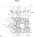
- Fig. 2 is an enlarged schematic sectional view of a turbine of the gas turbine according to the present embodiment.
- the rotor 150 includes the disks 114 and the turbine rotor blades 113.
- Each of the disks 114 rotates about a rotational axis RL illustrated in Figs. 1 and 2 .
- the turbine rotor blades 113 are connected to the radially outer periphery of the disk 114 formed in a disk shape, along the circumferential direction. In this manner, the turbine rotor blades 113 also rotate about the rotational axis RL with the disk 114.
- the combustion gas at a temperature and a pressure higher than those of the atmosphere produced in the combustor 130 is supplied to the turbine 110.
- the temperatures of the turbine rotor blades 113 and the disks 114 are increased, by receiving heat from the combustion gas.
- the gas turbine 1 supplies cooling air at a temperature lower than that of the turbine rotor blades 113 and the disks 114, to the turbine rotor blades 113 and the disks 114, thereby cooling the turbine rotor blades 113 and the disks 114.
- the disks 114 and the turbine rotor blades 113 are arranged in a plurality of stages, along the flow of combustion gas.
- a first disk 114a and a second disk 114b are the disks 114 arranged in this order from the upstream side of the flow of combustion gas.
- a first turbine rotor blade 113a and a second turbine rotor blade 113b are the turbine rotor blades 113 arranged in this order from the upstream side of the flow of combustion gas.
- the first turbine rotor blade 113a is connected to the first disk 114a
- the second turbine rotor blade 113b is connected to the second disk 114b.
- the turbine 110 includes a first supply passage 11, a first space 12, a radial passage 13, a second space 14, a cooling passage 15, a second supply passage 16, and a third space 17.
- the first supply passage 11 is a passage through which cooling air flows.
- the cooling air is supplied to the first supply passage 11 illustrated in Fig. 2 from the compressor 120 illustrated in Fig. 1 , through a passage, which is not illustrated, and a cooler that cools the air guided from the compressor 120.
- the first space 12 is formed in the rotor 150.
- a plurality of radial passages 13 is formed in the first disk 114a, from the inside of the first disk 114a formed in a disk shape, towards the radially outside of the first disk 114a.
- the second space 14 is formed between the first disk 114a and the first turbine rotor blade 113a.
- a plurality of cooling passages 15 is formed in the first turbine rotor blade 113a.
- the cooling air is supplied from one of the open ends of the first supply passage 11, and the other end is opened to the first space 12. In this manner, the cooling air is supplied to the first space 12 through the first supply passage 11. An open end 13a of the radial passage 13 is opened to the first space 12, and the other open end 13b is opened to the second space 14. Accordingly, the cooling air in the first space 12 is supplied to the second space 14 through the radial passage 13. At this time, while passing through the inside of the radial passage 13, the cooling air exchanges heat with the first disk 114a at a temperature higher than that of the cooling air. In this manner, the cooling air cools the first disk 114a, while passing through the radial passage 13.
- each of the cooling passages 15 is opened to the second space 14, and the other end is opened to the turbine casing 111.
- the cooling air in the second space 14 is discharged to the turbine casing 111 through the cooling passage 15.
- the cooling air exchanges heat with the first turbine rotor blade 113a at a temperature higher than that of the cooling air.
- the cooling air cools the first turbine rotor blade 113a, while passing through the cooling passage 15.
- the second supply passage 16 is formed in the first disk 114a in the direction of the rotational axis RL.
- the third space 17 is formed between the first disk 114a and the second disk 114b.
- One of the ends of the second supply passage 16 is opened to the first space 12, and the other end is opened to the third space 17. In this manner, in the cooling air in the first space 12, the cooling air that is not supplied to the radial passage 13 is guided to the third space 17, through the second supply passage 16.
- the cooling air in the third space 17 cools the second disk 114b and the second turbine rotor blade 113b, by flowing through the passages, the spaces, and the cooling passages formed in the second disk 114b and the second turbine rotor blade 113b, as in the first disk 114a and the first turbine rotor blade 113a.
- the radial passage 13 is formed in parallel with a plane perpendicular to the rotational axis RL. However, the radial passage 13 may be tilted relative to the plane perpendicular to the rotational axis RL.
- Fig. 3 is a projection view of radial passages formed in a disk according to the present embodiment, projected on a plane perpendicular to the rotational axis from the rotational axis direction.
- One of the features of the gas turbine 1 is the radial passages 13 formed in the disk 114.
- a virtual plane V01 is any plane that includes the rotational axis RL.
- the radial passages 13 are provided from the radially inside toward the radially outside of the disk 114.
- Each of the radial passages 13 intersects with the virtual plane V01 that passes through the rotational axis RL, or is in parallel with the virtual plane V01.
- the radial passage 13 is not completely included in the virtual plane V01.
- the virtual line of the radial passage 13 obtained by extending the radial passage 13 toward the radially inside of the disk 114 does not intersect with the rotational axis RL.
- a virtual reference plane V02 is a virtual plane including the open end 13a of the radial passage 13, and the rotational axis RL.
- an angle ⁇ between the virtual reference plane V02 and the radial passage 13, for example, is set to 30 degrees.
- the angles ⁇ between the virtual reference planes V02 and the radial passages 13 are equally set to 30 degrees.
- the present invention is not limited thereto.
- the angles ⁇ between the virtual reference planes V02 and the radial passages 13 may be set differently.
- Fitting units 18 illustrated in Fig. 3 are portions into which the ends of the turbine rotor blades 113 are fitted. By being fitted into a fitting unit formed at the end of the turbine rotor blade 113, the fitting unit 18 supports the turbine rotor blade 113 at the side periphery of the disk 114.
- the radial passages 13 are formed from the radially outside of the disk 114 toward the radially inside of the disk 114, for example, by a drill. In this manner, the open ends 13b are opened between the fitting units 18.
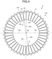
- Fig. 4 is a projection view of radial passages formed in a conventional disk, projected on a plane perpendicular to the rotational axis from the rotational axis direction.
- Fig. 5 is a schematic of a side periphery of the conventional disk spread into a plane.
- a conventional gas turbine 2, as illustrated in Fig. 4 includes a disk 214 and radial passages 23 formed in the disk 214. Open ends 23b of the radial passages 23 are opened at the side periphery of the disk 214.
- each of the open ends 23b of the radial passage 23, as illustrated in Fig. 5 is almost a true circle. If the disk 214 rotates about the rotational axis RL illustrated in Fig. 4 , force F is applied to the open ends 23b in the circumferential direction of the disk 214 by the inertial force. In this manner, the stress is generated at the open ends 23b. At this time, in the edge of the open end 23b that is an almost true circle, the stresses at regions P that pass through the centroid of the open end 23b and that are perpendicular to the force F become maximum. In other words, in the gas turbine 2, the stresses are concentrated on the regions P.
- Fig. 6 is a schematic of a side periphery of the disk according to the present embodiment spread into a plane.
- the angle ⁇ is set other than 0 degree
- the open ends 13b of the radial passages 13 are formed into oval shapes longer in the circumferential direction of the disk 114, as illustrated in Fig. 6 .
- the length w in the circumferential direction of the disk 114 is longer than the length h in the direction parallel to the rotational axis RL.
- the force F is applied to the radial passages 13 in the circumferential direction of the disk 114.
- the force F applied to the open ends 13b and the force F applied to the open ends 23b are equal.
- the shapes of the openings are different, even if the same force F is applied to the openings, the amount of stress generated in the specific region P is different.
- the stresses generated in the regions P that pass through the centroid of the open end 13b formed in an oval shape, and that is perpendicular to the force F, are smaller than the stresses generated in the regions P of the open end 23b formed in a true circle.
- the stresses generated in the regions P of the open end 13b are reduced, thereby reducing the uneven stress distribution generated in the open end 13b.
- the stresses generated in the regions P are increased, unlike when the length w in the circumferential direction of the disk 114 is longer than the length h in the direction parallel to the rotational axis RL.
- the shape at each of the open ends 13a of the radial passages 13 illustrated in Fig. 3 is also formed in an oval shape, as the open end 13b.
- the stresses generated in the regions P at the open end 13a are also reduced. Accordingly, in the gas turbine 1, the uneven stress distribution generated in the open end 13a is reduced.
- a virtual curved plane V03 is a virtual curved plane that is a curved plane about the rotational axis RL, and in which predetermine distances ⁇ from all the points on the curved plane to the rotational axis RL are all equal.
- the virtual curved plane V03 rotates about the rotational axis RL, and is a side surface of a cylinder in which the radius of the bottom surface and the upper surface is a predetermined distance ⁇ .
- the predetermined distance ⁇ is a distance equal to or more than a distance from the rotational axis RL to the open end 13a, and equal to or less than a distance from the rotational axis RL to the open end 13b.
- the length w in the circumferential direction of the disk 114 is longer than the length h in the direction parallel to the rotational axis RL. In this manner, in the gas turbine 1, similar to the open end 13a and the open end 13b, the stresses generated in regions that pass through the centroid of the cross-section and that are perpendicular to the force F applied to the edge of the cross-section, are reduced.
- the uneven stress distribution generated in the cross-section is reduced.
- the uneven stress distribution generated in the radial passage 13 is reduced, as well as in the open end 13a and the open end 13b.
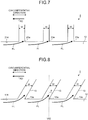
- Fig. 7 is a projection view of the radial passages formed in the conventional disk near inner open ends, projected on a plane perpendicular to the rotational axis from the rotational axis direction.
- Fig. 8 is a projection view of the radial passages formed in the disk according to the present embodiment near inner open ends, projected on a plane perpendicular to the rotational axis from the rotational axis direction.
- the cooling air is guided to the radial passage 13 from the first space 12 illustrated in Fig. 2 , through the open end 13a.
- the disk 114 rotates in a predetermined rotational direction. In this manner, when viewed from the radial passage 13, as illustrated in Fig. 8 by arrows FL, the cooling air seems to flow into the open ends 13a.
- the angle ⁇ is 0 degree. Accordingly, as illustrated in arrows FL in Fig. 7 , the cooling air collides with the wall surfaces of the open ends 23a. Accordingly, the cooling air does not flow into the radial passages 23 easily.
- the angle ⁇ is formed between the radial passage 13 and the virtual reference plane V02.
- the radial passages 13 are tilted relative to the virtual reference plane V02.
- the radial passages 13 are tilted toward the region opposite from the rotational direction of the disk 114 illustrated in Figs. 3 and 8 by the arrow RD, relative to the virtual reference plane V02.
- the cooling air flows into the radial passages 13, because the collision of the cooling air with the wall surfaces of the open ends 13a is eased. In other words, the cooling air flows into the radial passages 13 more easily than into the radial passages 23.
- the length w in the circumferential direction of the disk 114 is longer than the length w of the open ends 23a in the circumferential direction of the disk 214 illustrated in Figs. 5 and 7 , because the open ends 13a are formed in oval shapes. Accordingly, as illustrated in the arrows FL in Fig. 8 , the cooling air flows into the open ends 13a more easily than into the open ends 23a.
- the passage of the radial passage 13 through which the cooling air flows is longer than that of the radial passage 23 illustrated in Fig. 4 , because the radial passage 13 is tilted relative to the virtual reference plane V02. Accordingly, in the gas turbine 1 that includes the radial passages 13, the contact area of the cooling air and the turbine rotor blades 113 is increased. In this manner, in the gas turbine 1, the heat exchange between the cooling air and the turbine rotor blades 113 is further enhanced. In other words, the turbine rotor blades 113 in the gas turbine 1 are cooled more.
- the angle ⁇ for example, is set to 30 degrees. However, the present embodiment is not limited thereto. If the angle ⁇ is set equal to or more than 10 degrees and equal to or less than 45 degrees, in the gas turbine 1, the uneven stress distribution generated in the radial passage 13 is reduced. Accordingly, the cooling performance of the gas turbine 1 by the cooling air is enhanced.
- the radial passages 13 are formed from the radially outside of the disk 114 toward the radially inside of the disk 114, for example, by the drill. An embodiment of a method for forming the radial passage 13 will now be described.
- a drill blade D is shifted from the virtual plane V01 to a position separated by a predetermined distance ⁇ , and while forming the radial passages 13, the drill blade D is moved parallel to the virtual plane V01.
- Fig. 9 is a schematic for explaining a shifting amount of a drill blade from a virtual plane, while forming the radial passage according to the present embodiment.
- the predetermined distance ⁇ is calculated by a distance r from the rotational axis RL to the open end 13a, and the angle ⁇ . More specifically, the predetermined distance ⁇ is a product of the distance r and sin ⁇ .
- the worker then rotates the disk 114 about the rotational axis RL by a predetermined angle.
- the predetermined angle is calculated by the number of radial passages 13 to be provided in the disk 114. For example, if a predetermined number ⁇ of the radial passages 13 are formed in the disk 114, the disk 114 is rotated by an angle obtained by dividing 360 by the predetermined number ⁇ . At this state, the worker forms the second radial passage 13. Thereafter, the worker repeats the procedure of rotating the disk by a predetermined angle and the procedure of forming the radial passage 13, until a desired number of radial passages 13 are formed in the disk 114.
- the radial passages 13 can be easily formed by using a conventional machine tool. Accordingly, in the gas turbine 1 that includes the radial passages 13, as described above, the uneven stress distribution generated in the radial passages 13 is reduced. In the gas turbine 1 that includes the radial passages 13, as described above, the disks 114 and the turbine rotor blades 113 are cooled more appropriately.
- the radial passages 13 are formed in straight lines.
- Each of the radial passages 13, for example, may be formed in a shape in which a plurality of straight lines is combined, in other words, in a bent shape.
- the portion with the angle ⁇ is preferably formed near the open end 13a or the open end 13b of the radial passage 13.
- the cooling air flows into the open end 13a of the tilted radial passage 13 easily. Accordingly, in the gas turbine 1, the disks 114 and the turbine rotor blades 113 are cooled more.
- the open end 13b is most separated from the rotational axis RL, in the radial passage 13 formed in the disk 114. Accordingly, the largest force F is applied to the portion near the open end 13b in the radial passage 13. Consequently, if the portion with the angle ⁇ is formed near the open end 13b in the radial passage 13, in the gas turbine 1, the uneven stress distribution generated in the portion where the largest force F is applied in the radial passage 13 is reduced.
- the angle ⁇ may be set to 0 degree.
- the cross-section of the radial passage 13 at the virtual curved plane V03 is formed in an oval shape, unlike the radial passage 23 illustrated in Figs. 4 and 5 .
- the radial passages 13 are formed by electric spark machining.
- the cross-sections of the radial passages 13 at the virtual curved plane V03 are formed in oval shapes in which the length w in the circumferential direction of the disk 114 is longer than the length h in the direction parallel to the rotational axis RL. Accordingly, in the gas turbine 1, as described above, the uneven stress distribution generated in the radial passage 13 is reduced.
- the "oval shape” in the present embodiment is not necessarily limited to an accurate oval shape.
- the shape of the cross-section of the radial passage 13 at the virtual curved plane V03 is not limited to a curve formed by a collection of points in which the sum of the distances from two specific points on the plane is constant.
- the shape of the cross-section of the radial passage 13 at the virtual curved plane V03 may be any shape provided it is an almost oval shape without a corner.
- a gas turbine, a disk, and a method for forming a radial passage of a disk according to the present embodiment can be advantageously used for a gas turbine that includes radial passages through which cooling air flows in the radial direction of the disk. More specifically, a gas turbine, a disk, and a method for forming a radial passage of a disk according to the present embodiment are suitable for a gas turbine that reduces uneven stress distribution generated in the radial passage.
Landscapes
- Engineering & Computer Science (AREA)
- Mechanical Engineering (AREA)
- General Engineering & Computer Science (AREA)
- Turbine Rotor Nozzle Sealing (AREA)
Applications Claiming Priority (2)
| Application Number | Priority Date | Filing Date | Title |
|---|---|---|---|
| JP2008048249A JP4981709B2 (ja) | 2008-02-28 | 2008-02-28 | ガスタービン及びディスク並びにディスクの径方向通路形成方法 |
| PCT/JP2008/073483 WO2009107312A1 (ja) | 2008-02-28 | 2008-12-24 | ガスタービン及びディスク並びにディスクの径方向通路形成方法 |
Publications (3)
| Publication Number | Publication Date |
|---|---|
| EP2246525A1 EP2246525A1 (en) | 2010-11-03 |
| EP2246525A4 EP2246525A4 (en) | 2013-05-01 |
| EP2246525B1 true EP2246525B1 (en) | 2017-08-09 |
Family
ID=41015718
Family Applications (1)
| Application Number | Title | Priority Date | Filing Date |
|---|---|---|---|
| EP08872916.5A Active EP2246525B1 (en) | 2008-02-28 | 2008-12-24 | Gas turbine comprising a turbine disk and method for forming a radial passage of the turbine disk |
Country Status (6)
| Country | Link |
|---|---|
| US (1) | US20100326039A1 (ja) |
| EP (1) | EP2246525B1 (ja) |
| JP (1) | JP4981709B2 (ja) |
| KR (1) | KR101318476B1 (ja) |
| CN (1) | CN101952555A (ja) |
| WO (1) | WO2009107312A1 (ja) |
Families Citing this family (11)
| Publication number | Priority date | Publication date | Assignee | Title |
|---|---|---|---|---|
| US20130017059A1 (en) * | 2011-07-15 | 2013-01-17 | United Technologies Corporation | Hole for rotating component cooling system |
| CN103206270A (zh) * | 2013-04-25 | 2013-07-17 | 北京华清燃气轮机与煤气化联合循环工程技术有限公司 | 一种冷却燃气轮机涡轮盘及动叶片的方法 |
| CN104929692A (zh) | 2014-03-19 | 2015-09-23 | 阿尔斯通技术有限公司 | 带有冷却孔入口的转子轴 |
| CN104454025B (zh) * | 2014-11-12 | 2015-11-18 | 中国科学院工程热物理研究所 | 一种用于高温旋转轮盘的冷却结构 |
| KR101675269B1 (ko) * | 2015-10-02 | 2016-11-11 | 두산중공업 주식회사 | 가스터빈 디스크 |
| PL415045A1 (pl) * | 2015-12-03 | 2017-06-05 | General Electric Company | Tarcze turbiny i sposoby ich wytwarzania |
| US10024170B1 (en) * | 2016-06-23 | 2018-07-17 | Florida Turbine Technologies, Inc. | Integrally bladed rotor with bore entry cooling holes |
| WO2019066750A2 (en) * | 2017-05-23 | 2019-04-04 | Uyanik Talat | TURBINE COOLING FOR GAS TURBINE ENGINES |
| CN108374692B (zh) * | 2018-01-25 | 2020-09-01 | 南方科技大学 | 一种涡轮轮盘及涡轮发动机 |
| US10794190B1 (en) * | 2018-07-30 | 2020-10-06 | Florida Turbine Technologies, Inc. | Cast integrally bladed rotor with bore entry cooling |
| JP7328794B2 (ja) | 2019-05-24 | 2023-08-17 | 三菱重工業株式会社 | ロータディスク、ロータ軸、タービンロータ、及びガスタービン |
Family Cites Families (26)
| Publication number | Priority date | Publication date | Assignee | Title |
|---|---|---|---|---|
| US2613058A (en) * | 1945-11-30 | 1952-10-07 | Atkinson Joseph | Cooled bladed rotor |
| FR2146907B1 (ja) * | 1971-07-23 | 1975-02-21 | Snecma | |
| US3814539A (en) * | 1972-10-04 | 1974-06-04 | Gen Electric | Rotor sealing arrangement for an axial flow fluid turbine |
| US3918835A (en) * | 1974-12-19 | 1975-11-11 | United Technologies Corp | Centrifugal cooling air filter |
| US3936215A (en) * | 1974-12-20 | 1976-02-03 | United Technologies Corporation | Turbine vane cooling |
| US4203705A (en) * | 1975-12-22 | 1980-05-20 | United Technologies Corporation | Bonded turbine disk for improved low cycle fatigue life |
| US4093399A (en) * | 1976-12-01 | 1978-06-06 | Electric Power Research Institute, Inc. | Turbine rotor with ceramic blades |
| FR2552817B1 (fr) * | 1978-11-27 | 1988-02-12 | Snecma | Perfectionnements au refroidissement des rotors de turbines |
| US4344738A (en) * | 1979-12-17 | 1982-08-17 | United Technologies Corporation | Rotor disk structure |
| JPS6043101A (ja) * | 1983-08-17 | 1985-03-07 | Toshiba Corp | タ−ビンホイ−ル |
| CN85102116A (zh) * | 1985-04-01 | 1987-01-31 | 联合工艺公司 | 转子装配件叶片紧固槽的密封装置 |
| FR2614654B1 (fr) * | 1987-04-29 | 1992-02-21 | Snecma | Disque de compresseur axial de turbomachine a prelevement d'air centripete |
| JPH09242563A (ja) * | 1996-03-11 | 1997-09-16 | Hitachi Ltd | ガスタービン冷却システム |
| GB9615394D0 (en) * | 1996-07-23 | 1996-09-04 | Rolls Royce Plc | Gas turbine engine rotor disc with cooling fluid passage |
| JPH10103001A (ja) * | 1996-09-25 | 1998-04-21 | Ishikawajima Harima Heavy Ind Co Ltd | 回転機械のロータ |
| JPH10121903A (ja) * | 1996-10-21 | 1998-05-12 | Toshiba Corp | ガスタービンロータ |
| DE19705442A1 (de) * | 1997-02-13 | 1998-08-20 | Bmw Rolls Royce Gmbh | Turbinen-Laufradscheibe mit Kühlluftkanälen |
| DE59709507D1 (de) * | 1997-07-28 | 2003-04-17 | Alstom Switzerland Ltd | Rotor einer Strömungsmaschine |
| JP4040773B2 (ja) * | 1998-12-01 | 2008-01-30 | 株式会社東芝 | ガスタービンプラント |
| JP4067709B2 (ja) * | 1999-08-23 | 2008-03-26 | 三菱重工業株式会社 | ロータ冷却空気供給装置 |
| JP2001329859A (ja) * | 2000-05-23 | 2001-11-30 | Mitsubishi Heavy Ind Ltd | タービンの動翼構造 |
| US6468032B2 (en) * | 2000-12-18 | 2002-10-22 | Pratt & Whitney Canada Corp. | Further cooling of pre-swirl flow entering cooled rotor aerofoils |
| US6760961B2 (en) * | 2002-02-12 | 2004-07-13 | Focus: Hope | Piston machining |
| US6760971B2 (en) * | 2002-07-15 | 2004-07-13 | Pratt & Whitney Canada Corp. | Method of making a gas turbine engine diffuser |
| US6837676B2 (en) * | 2002-09-11 | 2005-01-04 | Mitsubishi Heavy Industries, Ltd. | Gas turbine |
| JP4291738B2 (ja) * | 2004-05-26 | 2009-07-08 | 株式会社日立製作所 | 二軸式ガスタービン |
-
2008
- 2008-02-28 JP JP2008048249A patent/JP4981709B2/ja active Active
- 2008-12-24 EP EP08872916.5A patent/EP2246525B1/en active Active
- 2008-12-24 CN CN2008801270316A patent/CN101952555A/zh active Pending
- 2008-12-24 KR KR1020107017728A patent/KR101318476B1/ko active IP Right Grant
- 2008-12-24 WO PCT/JP2008/073483 patent/WO2009107312A1/ja active Application Filing
- 2008-12-24 US US12/865,641 patent/US20100326039A1/en not_active Abandoned
Non-Patent Citations (1)
| Title |
|---|
| None * |
Also Published As
| Publication number | Publication date |
|---|---|
| KR101318476B1 (ko) | 2013-10-18 |
| CN101952555A (zh) | 2011-01-19 |
| JP4981709B2 (ja) | 2012-07-25 |
| JP2009203926A (ja) | 2009-09-10 |
| US20100326039A1 (en) | 2010-12-30 |
| EP2246525A1 (en) | 2010-11-03 |
| EP2246525A4 (en) | 2013-05-01 |
| KR20100102211A (ko) | 2010-09-20 |
| WO2009107312A1 (ja) | 2009-09-03 |
Similar Documents
| Publication | Publication Date | Title |
|---|---|---|
| EP2246525B1 (en) | Gas turbine comprising a turbine disk and method for forming a radial passage of the turbine disk | |
| US10513932B2 (en) | Cooling pedestal array | |
| EP3244011B1 (en) | System for cooling seal rails of tip shroud of turbine blade | |
| JP5503140B2 (ja) | 発散型タービンノズル | |
| US11448076B2 (en) | Engine component with cooling hole | |
| RU2577688C2 (ru) | Лопатка для турбомашины и турбомашина, содержащая такую лопатку. | |
| EP3163023B1 (en) | Turbine bucket with cooling passage in the shroud | |
| EP3214271B1 (en) | Rotor blade trailing edge cooling | |
| CN107448300A (zh) | 用于涡轮发动机的翼型件 | |
| US10815789B2 (en) | Impingement holes for a turbine engine component | |
| EP3163025B1 (en) | Turbine bucket having outlet path in shroud | |
| US10619490B2 (en) | Turbine rotor blade arrangement for a gas turbine and method for the provision of sealing air in a turbine rotor blade arrangement | |
| CN102383863A (zh) | 用于在燃气涡轮发动机中使用的转子组件及其组装方法 | |
| US20170298743A1 (en) | Component for a turbine engine with a film-hole | |
| JP2012047171A (ja) | タービンステージのシュラウドセグメント | |
| JP6554736B2 (ja) | ガスタービンロータ、ガスタービン、及びガスタービン設備 | |
| JP5507340B2 (ja) | ターボ機械圧縮機ホイール部材 | |
| EP3221561B1 (en) | Blade platform cooling in a gas turbine and gas turbine | |
| CN107438701A (zh) | 涡轮机翼型件的在两个压力下的冷却 | |
| EP3241991A1 (en) | Turbine assembly | |
| EP3717747B1 (en) | Internally-cooled turbomachine component | |
| EP3653839A1 (en) | Turbine aerofoil | |
| EP3835545B1 (en) | Turbine rotor | |
| EP2378071A1 (en) | Turbine assembly having cooling arrangement and method of cooling | |
| EP3470631A1 (en) | Heatshield apparatus |
Legal Events
| Date | Code | Title | Description |
|---|---|---|---|
| PUAI | Public reference made under article 153(3) epc to a published international application that has entered the european phase |
Free format text: ORIGINAL CODE: 0009012 |
|
| 17P | Request for examination filed |
Effective date: 20100714 |
|
| AK | Designated contracting states |
Kind code of ref document: A1 Designated state(s): AT BE BG CH CY CZ DE DK EE ES FI FR GB GR HR HU IE IS IT LI LT LU LV MC MT NL NO PL PT RO SE SI SK TR |
|
| AX | Request for extension of the european patent |
Extension state: AL BA MK RS |
|
| DAX | Request for extension of the european patent (deleted) | ||
| A4 | Supplementary search report drawn up and despatched |
Effective date: 20130328 |
|
| RIC1 | Information provided on ipc code assigned before grant |
Ipc: F02C 7/18 20060101ALI20130322BHEP Ipc: F01D 5/08 20060101AFI20130322BHEP |
|
| 17Q | First examination report despatched |
Effective date: 20160120 |
|
| GRAP | Despatch of communication of intention to grant a patent |
Free format text: ORIGINAL CODE: EPIDOSNIGR1 |
|
| INTG | Intention to grant announced |
Effective date: 20170316 |
|
| GRAS | Grant fee paid |
Free format text: ORIGINAL CODE: EPIDOSNIGR3 |
|
| GRAA | (expected) grant |
Free format text: ORIGINAL CODE: 0009210 |
|
| RIN1 | Information on inventor provided before grant (corrected) |
Inventor name: HASHIMOTO, SHINYA Inventor name: ARASE, KENICHI |
|
| AK | Designated contracting states |
Kind code of ref document: B1 Designated state(s): AT BE BG CH CY CZ DE DK EE ES FI FR GB GR HR HU IE IS IT LI LT LU LV MC MT NL NO PL PT RO SE SI SK TR |
|
| REG | Reference to a national code |
Ref country code: GB Ref legal event code: FG4D |
|
| REG | Reference to a national code |
Ref country code: CH Ref legal event code: EP Ref country code: AT Ref legal event code: REF Ref document number: 917079 Country of ref document: AT Kind code of ref document: T Effective date: 20170815 |
|
| REG | Reference to a national code |
Ref country code: IE Ref legal event code: FG4D |
|
| REG | Reference to a national code |
Ref country code: DE Ref legal event code: R096 Ref document number: 602008051584 Country of ref document: DE |
|
| REG | Reference to a national code |
Ref country code: NL Ref legal event code: MP Effective date: 20170809 |
|
| REG | Reference to a national code |
Ref country code: LT Ref legal event code: MG4D |
|
| REG | Reference to a national code |
Ref country code: AT Ref legal event code: MK05 Ref document number: 917079 Country of ref document: AT Kind code of ref document: T Effective date: 20170809 |
|
| PG25 | Lapsed in a contracting state [announced via postgrant information from national office to epo] |
Ref country code: NO Free format text: LAPSE BECAUSE OF FAILURE TO SUBMIT A TRANSLATION OF THE DESCRIPTION OR TO PAY THE FEE WITHIN THE PRESCRIBED TIME-LIMIT Effective date: 20171109 Ref country code: NL Free format text: LAPSE BECAUSE OF FAILURE TO SUBMIT A TRANSLATION OF THE DESCRIPTION OR TO PAY THE FEE WITHIN THE PRESCRIBED TIME-LIMIT Effective date: 20170809 Ref country code: FI Free format text: LAPSE BECAUSE OF FAILURE TO SUBMIT A TRANSLATION OF THE DESCRIPTION OR TO PAY THE FEE WITHIN THE PRESCRIBED TIME-LIMIT Effective date: 20170809 Ref country code: SE Free format text: LAPSE BECAUSE OF FAILURE TO SUBMIT A TRANSLATION OF THE DESCRIPTION OR TO PAY THE FEE WITHIN THE PRESCRIBED TIME-LIMIT Effective date: 20170809 Ref country code: AT Free format text: LAPSE BECAUSE OF FAILURE TO SUBMIT A TRANSLATION OF THE DESCRIPTION OR TO PAY THE FEE WITHIN THE PRESCRIBED TIME-LIMIT Effective date: 20170809 Ref country code: HR Free format text: LAPSE BECAUSE OF FAILURE TO SUBMIT A TRANSLATION OF THE DESCRIPTION OR TO PAY THE FEE WITHIN THE PRESCRIBED TIME-LIMIT Effective date: 20170809 Ref country code: LT Free format text: LAPSE BECAUSE OF FAILURE TO SUBMIT A TRANSLATION OF THE DESCRIPTION OR TO PAY THE FEE WITHIN THE PRESCRIBED TIME-LIMIT Effective date: 20170809 |
|
| PG25 | Lapsed in a contracting state [announced via postgrant information from national office to epo] |
Ref country code: IS Free format text: LAPSE BECAUSE OF FAILURE TO SUBMIT A TRANSLATION OF THE DESCRIPTION OR TO PAY THE FEE WITHIN THE PRESCRIBED TIME-LIMIT Effective date: 20171209 Ref country code: ES Free format text: LAPSE BECAUSE OF FAILURE TO SUBMIT A TRANSLATION OF THE DESCRIPTION OR TO PAY THE FEE WITHIN THE PRESCRIBED TIME-LIMIT Effective date: 20170809 Ref country code: PL Free format text: LAPSE BECAUSE OF FAILURE TO SUBMIT A TRANSLATION OF THE DESCRIPTION OR TO PAY THE FEE WITHIN THE PRESCRIBED TIME-LIMIT Effective date: 20170809 Ref country code: GR Free format text: LAPSE BECAUSE OF FAILURE TO SUBMIT A TRANSLATION OF THE DESCRIPTION OR TO PAY THE FEE WITHIN THE PRESCRIBED TIME-LIMIT Effective date: 20171110 Ref country code: LV Free format text: LAPSE BECAUSE OF FAILURE TO SUBMIT A TRANSLATION OF THE DESCRIPTION OR TO PAY THE FEE WITHIN THE PRESCRIBED TIME-LIMIT Effective date: 20170809 Ref country code: BG Free format text: LAPSE BECAUSE OF FAILURE TO SUBMIT A TRANSLATION OF THE DESCRIPTION OR TO PAY THE FEE WITHIN THE PRESCRIBED TIME-LIMIT Effective date: 20171109 |
|
| PG25 | Lapsed in a contracting state [announced via postgrant information from national office to epo] |
Ref country code: RO Free format text: LAPSE BECAUSE OF FAILURE TO SUBMIT A TRANSLATION OF THE DESCRIPTION OR TO PAY THE FEE WITHIN THE PRESCRIBED TIME-LIMIT Effective date: 20170809 Ref country code: DK Free format text: LAPSE BECAUSE OF FAILURE TO SUBMIT A TRANSLATION OF THE DESCRIPTION OR TO PAY THE FEE WITHIN THE PRESCRIBED TIME-LIMIT Effective date: 20170809 Ref country code: CZ Free format text: LAPSE BECAUSE OF FAILURE TO SUBMIT A TRANSLATION OF THE DESCRIPTION OR TO PAY THE FEE WITHIN THE PRESCRIBED TIME-LIMIT Effective date: 20170809 |
|
| REG | Reference to a national code |
Ref country code: DE Ref legal event code: R097 Ref document number: 602008051584 Country of ref document: DE |
|
| PG25 | Lapsed in a contracting state [announced via postgrant information from national office to epo] |
Ref country code: IT Free format text: LAPSE BECAUSE OF FAILURE TO SUBMIT A TRANSLATION OF THE DESCRIPTION OR TO PAY THE FEE WITHIN THE PRESCRIBED TIME-LIMIT Effective date: 20170809 Ref country code: SK Free format text: LAPSE BECAUSE OF FAILURE TO SUBMIT A TRANSLATION OF THE DESCRIPTION OR TO PAY THE FEE WITHIN THE PRESCRIBED TIME-LIMIT Effective date: 20170809 Ref country code: EE Free format text: LAPSE BECAUSE OF FAILURE TO SUBMIT A TRANSLATION OF THE DESCRIPTION OR TO PAY THE FEE WITHIN THE PRESCRIBED TIME-LIMIT Effective date: 20170809 |
|
| PLBE | No opposition filed within time limit |
Free format text: ORIGINAL CODE: 0009261 |
|
| STAA | Information on the status of an ep patent application or granted ep patent |
Free format text: STATUS: NO OPPOSITION FILED WITHIN TIME LIMIT |
|
| 26N | No opposition filed |
Effective date: 20180511 |
|
| REG | Reference to a national code |
Ref country code: CH Ref legal event code: PL |
|
| GBPC | Gb: european patent ceased through non-payment of renewal fee |
Effective date: 20171224 |
|
| PG25 | Lapsed in a contracting state [announced via postgrant information from national office to epo] |
Ref country code: SI Free format text: LAPSE BECAUSE OF FAILURE TO SUBMIT A TRANSLATION OF THE DESCRIPTION OR TO PAY THE FEE WITHIN THE PRESCRIBED TIME-LIMIT Effective date: 20170809 |
|
| REG | Reference to a national code |
Ref country code: IE Ref legal event code: MM4A |
|
| PG25 | Lapsed in a contracting state [announced via postgrant information from national office to epo] |
Ref country code: LU Free format text: LAPSE BECAUSE OF NON-PAYMENT OF DUE FEES Effective date: 20171224 Ref country code: MT Free format text: LAPSE BECAUSE OF NON-PAYMENT OF DUE FEES Effective date: 20171224 |
|
| REG | Reference to a national code |
Ref country code: FR Ref legal event code: ST Effective date: 20180831 |
|
| REG | Reference to a national code |
Ref country code: BE Ref legal event code: MM Effective date: 20171231 |
|
| PG25 | Lapsed in a contracting state [announced via postgrant information from national office to epo] |
Ref country code: IE Free format text: LAPSE BECAUSE OF NON-PAYMENT OF DUE FEES Effective date: 20171224 Ref country code: FR Free format text: LAPSE BECAUSE OF NON-PAYMENT OF DUE FEES Effective date: 20180102 |
|
| PG25 | Lapsed in a contracting state [announced via postgrant information from national office to epo] |
Ref country code: LI Free format text: LAPSE BECAUSE OF NON-PAYMENT OF DUE FEES Effective date: 20171231 Ref country code: BE Free format text: LAPSE BECAUSE OF NON-PAYMENT OF DUE FEES Effective date: 20171231 Ref country code: GB Free format text: LAPSE BECAUSE OF NON-PAYMENT OF DUE FEES Effective date: 20171224 Ref country code: CH Free format text: LAPSE BECAUSE OF NON-PAYMENT OF DUE FEES Effective date: 20171231 |
|
| PG25 | Lapsed in a contracting state [announced via postgrant information from national office to epo] |
Ref country code: MC Free format text: LAPSE BECAUSE OF FAILURE TO SUBMIT A TRANSLATION OF THE DESCRIPTION OR TO PAY THE FEE WITHIN THE PRESCRIBED TIME-LIMIT Effective date: 20170809 Ref country code: HU Free format text: LAPSE BECAUSE OF FAILURE TO SUBMIT A TRANSLATION OF THE DESCRIPTION OR TO PAY THE FEE WITHIN THE PRESCRIBED TIME-LIMIT; INVALID AB INITIO Effective date: 20081224 |
|
| PG25 | Lapsed in a contracting state [announced via postgrant information from national office to epo] |
Ref country code: CY Free format text: LAPSE BECAUSE OF NON-PAYMENT OF DUE FEES Effective date: 20170809 |
|
| PG25 | Lapsed in a contracting state [announced via postgrant information from national office to epo] |
Ref country code: TR Free format text: LAPSE BECAUSE OF FAILURE TO SUBMIT A TRANSLATION OF THE DESCRIPTION OR TO PAY THE FEE WITHIN THE PRESCRIBED TIME-LIMIT Effective date: 20170809 |
|
| PG25 | Lapsed in a contracting state [announced via postgrant information from national office to epo] |
Ref country code: PT Free format text: LAPSE BECAUSE OF FAILURE TO SUBMIT A TRANSLATION OF THE DESCRIPTION OR TO PAY THE FEE WITHIN THE PRESCRIBED TIME-LIMIT Effective date: 20170809 |
|
| REG | Reference to a national code |
Ref country code: DE Ref legal event code: R081 Ref document number: 602008051584 Country of ref document: DE Owner name: MITSUBISHI POWER, LTD., YOKOHAMA-SHI, JP Free format text: FORMER OWNER: MITSUBISHI HEAVY INDUSTRIES, LTD., TOKYO, JP |
|
| PGFP | Annual fee paid to national office [announced via postgrant information from national office to epo] |
Ref country code: DE Payment date: 20231031 Year of fee payment: 16 |