EP2245963A1 - Verbindungsvorrichtung - Google Patents
Verbindungsvorrichtung Download PDFInfo
- Publication number
- EP2245963A1 EP2245963A1 EP10161587A EP10161587A EP2245963A1 EP 2245963 A1 EP2245963 A1 EP 2245963A1 EP 10161587 A EP10161587 A EP 10161587A EP 10161587 A EP10161587 A EP 10161587A EP 2245963 A1 EP2245963 A1 EP 2245963A1
- Authority
- EP
- European Patent Office
- Prior art keywords
- connecting device
- unlocking
- furniture component
- distances
- adjusting holes
- Prior art date
- Legal status (The legal status is an assumption and is not a legal conclusion. Google has not performed a legal analysis and makes no representation as to the accuracy of the status listed.)
- Granted
Links
- 210000002105 tongue Anatomy 0.000 claims description 13
- 230000006835 compression Effects 0.000 claims description 5
- 238000007906 compression Methods 0.000 claims description 5
- 238000006073 displacement reaction Methods 0.000 claims description 3
- 238000005553 drilling Methods 0.000 description 2
- 238000005422 blasting Methods 0.000 description 1
Images



Classifications
-
- A—HUMAN NECESSITIES
- A47—FURNITURE; DOMESTIC ARTICLES OR APPLIANCES; COFFEE MILLS; SPICE MILLS; SUCTION CLEANERS IN GENERAL
- A47B—TABLES; DESKS; OFFICE FURNITURE; CABINETS; DRAWERS; GENERAL DETAILS OF FURNITURE
- A47B88/00—Drawers for tables, cabinets or like furniture; Guides for drawers
- A47B88/40—Sliding drawers; Slides or guides therefor
- A47B88/423—Fastening devices for slides or guides
- A47B88/427—Fastening devices for slides or guides at drawer side
-
- Y—GENERAL TAGGING OF NEW TECHNOLOGICAL DEVELOPMENTS; GENERAL TAGGING OF CROSS-SECTIONAL TECHNOLOGIES SPANNING OVER SEVERAL SECTIONS OF THE IPC; TECHNICAL SUBJECTS COVERED BY FORMER USPC CROSS-REFERENCE ART COLLECTIONS [XRACs] AND DIGESTS
- Y10—TECHNICAL SUBJECTS COVERED BY FORMER USPC
- Y10T—TECHNICAL SUBJECTS COVERED BY FORMER US CLASSIFICATION
- Y10T403/00—Joints and connections
- Y10T403/71—Rod side to plate or side
- Y10T403/7123—Traversed by connector
Definitions
- the invention relates to a connecting device for a first and a second to a unit connectable and mutually adjustable furniture components.
- the furniture components to be joined together are known in many embodiments.
- the components to be connected to a structural unit are displaceable in an oscillating manner relative to a guide fixedly mounted on the furniture body.
- the invention has the object of providing a connecting device of the kind described in more detail interpreted so that without the use of adjusting screws and without the aid of tools, the two can be adjusted to a unit to be joined furniture components against each other.
- the stated object is achieved in that at least two mutually spaced fasteners are provided in the second furniture component, and that in the first furniture component at least one of the number of fasteners corresponding number of Justierlöchern is provided, and that the distances of the fixing to the distances the adjusting holes are deviating and the connecting elements and the adjusting holes lie in the displacement plane.
- a furniture component can be moved relative to the other furniture component for the purpose of adjustment by a minimum amount in the displacement plane. Due to the different distances between the adjusting holes and the connecting elements, only one connecting element can engage in an associated adjusting hole. The remaining fasteners are based on the adjustment holes limiting edges, are therefore ineffective.
- the central adjustment hole and the central connecting element can each be regarded as an adjustment element for the basic setting for the furniture components and the two lateral adjusting holes and connecting element for the correction.
- the connecting elements are designed as in the longitudinal direction of the adjusting holes and in its longitudinal direction movable adjusting bolt.
- the respective adjusting bolt engaging in an adjusting hole engages over a part of the length in the respective adjusting hole.
- the distances between the connecting elements are larger or smaller than the distances between the adjusting holes. In one possible embodiment, however, it is still provided that the distances between the connecting elements are equal to one another.
- each connecting bolt is loaded by means of a respective force accumulator.
- the connecting bolts are provided at the end portions facing the power storage, each with a respective unlocking pins extending transversely to the central longitudinal axis of the respective connecting bolt. These unlocking pins make it possible for the connecting bolt, which is in each case immersed in an adjusting hole, to be brought into a release position, so that a subsequent adjustment is still possible or that the furniture components connected to one another can be decoupled.
- the guide channels are open at least on the side associated with the unlocking pins or have slots. Conveniently, however, the guide channels are open on the opposite sides. It should be noted that the guide plate is firmly connected to the second furniture component.
- the release of the respective connecting bolt can be achieved in the simplest manner, it is provided that on the guide plate on the unlocking pins associated side in the longitudinal direction of the locking bolt slidably guided unlocking slide is arranged, which is in operative connection with the unlocking pins.
- This operative connection is achieved in a particularly simple manner in that the unlocking slide is provided with an unlocking web provided on the side facing the connecting bolt, which is provided with recesses in which the unlocking pins engage. These recesses engage behind the unlocking pins.
- an actuating lever is pivotally mounted, on which the unlocking slide is articulated.
- the fixing elements are designed as spring tongues, which are attached to a holder, molded or formed. These spring tongues are designed so that the free end portions engage in one of the adjustment holes as soon as this spring tongue is aligned with the adjustment hole.
- the first furniture component that which has the Justierlöcher and the second furniture component is the component which is equipped with the connecting elements.
- the first furniture component is a running rail movable along a stationary guide rail and the second furniture component is the bottom of a drawer. The reversal is possible, so that the bottom of the drawer is the first furniture component and the running track is the second furniture component.
- connection device explained in more detail for connecting a drawer 10 partially shown with a running rail 11 is shown, which is movable along a fixedly attached to a furniture body, not shown, guide rail 12.
- guide rail 12 For the sake of simplified illustration, only the bottom 10a and a side wall 10b of the drawer 10 are shown.
- the running rail 11 is on the inner side facing away from the side wall 10b equipped with three equal height and at the same distance from each other adjusting holes 13.
- a guide plate 14 is fixed to the underside of the bottom 10a of the drawer 10. Because of the clearer explanation of the solution according to the invention, the guide plate 14 above the plane of the connecting pin 17 is shown cut away.
- This guide plate 14 is provided on the running rail 11 facing side with three spaced guides 15 which are formed as blind holes. However, the walls 15 delimiting walls extend arcuately.
- a power storage in the form of a compression spring 16 is used in each guide 15.
- a connecting pin 17 is inserted into each guide 15.
- an unlocking pin 18 which is transverse to the central longitudinal axis of each locking bolt 17 and penetrates through a slot 26, the guide plate 14.
- an unlocking slide 19 is slidably inserted on the guide plate 14. This unlocking slide 19 is provided on the side facing the running rail 11 with a Entriegelungssteg 20 which is transverse to the direction of the unlocking slide 19.
- the guide plate 14 On the side facing away from the running rail 11 of the Entriegelungssteg 20 is provided with slots in which the Entriegelungsloche Engage, the guide plate 14 is provided with a bore 21 into which an end-side pin 22 of an unlocking lever 23 is inserted. At this release lever 23 of the release slide 19 is hinged.
- the unlocking slide 19 is provided on the side facing away from the running rail 11 with a bearing pin 24 which engages in a bore 25 of the unlocking lever 23.
- FIG. 1 a shows the above-described connecting device in an oblique perspective and an exploded view, while the FIG. 1b this arrangement shows in a transversely to the extension direction blasting image representation.
- FIG. 2a shows one of the FIG. 1a corresponding representation, however, the connecting device is shown in the assembled state.
- the Figure 2c shows this connection device in a plan view and the FIG. 2b shows this connection device in a rotated position by 180 °, ie, in a bottom view perspective.
- the distances of the guides 15 and thus the connecting pins 17 are different from the distances between the individual adjustment holes 13, but are in the same plane.
- the distances of the guides 15 are slightly larger, for example by a range of two millimeters, than the distances between the adjusting holes 13
- FIGS. 2a, 2b, 2c show that in the illustrated embodiment, the middle connecting pin 17 is retracted in the associated central adjustment hole 13.
- either the drawer 10 or the running rail 11 can be moved so that one of the outer connecting pin 17 engages in the associated adjusting hole 13. In the starting position, all connecting bolts 17 are retracted.
- the running rail 11 forms the first furniture component and the drawer 10, the second furniture component, which form a structural unit by a respective adjusting hole 13 and a retracted connecting pin 17, wherein the components in operative connection with the connecting pin 17 belonging to the connecting device.
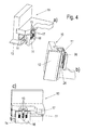
- FIGS. 3a, 3b . 4a, 4b, 4c show a reference to the previously discussed figures identical connection device, however, the adjustment holes 13 are formed as outgoing from the bottom of the bottom 10a of the drawer 10 blind holes.
- the guide plate 14, here again the page lying to the viewer is cut away to the level of the connecting elements, including the compression springs 16 and the connecting pin 17 and the unlocking slide 19 and the release lever 23 are fixed to the running rail 11. Accordingly, the guide plate 14 is parallel and at a distance from the side wall 10b of the drawer 10.
- the guide plate 14 is at a distance from the facing leg of the running rail 11.
- two intermediate webs 26 are attached or integrally formed on this leg of the running rail 11.
- the unlocking slide 19 is located between these webs in particular the Figures 4a, 4b and 4c demonstrate.
- FIG. 3 shows the connecting device in a perspective and an exploded view
- the FIG. 3b shows the connecting device in an exploded side view with a view of the side wall 10b of the drawer 10
- the FIG. 4a shows the connecting device according to the FIG. 3a , but in the assembled state
- the Figure 4c shows the assembled connection device in a side view with a view of the side wall 10b of the drawer 10
- the FIG. 4b shows the connecting device in a bottom view overlooking the bottom 10 a of the drawer 10th
- the in the FIGS. 3a to 4c shown connecting device is a reversal of the in the FIGS. 1a to 2c shown device. Accordingly, in this embodiment, the bottom 10a of the drawer 10, the first furniture component and the running rail 11 with the attached guide plate 14, the second furniture component.
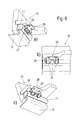
- the FIGS. 5a, 5b . 6a, 6b and 6c show a third embodiment of the connecting device according to the invention.
- the FIG. 5a shows these in a perspective and an exploded view with respect to the inner surface of the side wall 10b of the drawer 10 and the FIG. 5b shows this embodiment with a view of the outer surface of the side wall 10b of the drawer 10th Die FIG.
- FIG. 6a shows this connection device in the assembled state in a perspective view of the running rail 11 and the lower side of the bottom 10a of the drawer 10th Die
- FIG. 6b shows this connection device in a side view and the FIG. 6c this connection device in a perspective view overlooking the lower surface of the bottom 10a of the drawer 10th
- FIG. 5a shows the Justierlöcher 13 are also arranged in this embodiment in the track rail 11, but they are designed rectangular in contrast to the previously described embodiments, wherein the distances are again the same.
- spring tongues 27 which are integrally formed on a holder 28 having a mounting plate to set this at the bottom of the bottom 10a of the drawer 10.
- the spacings of the spring tongues 27 also deviate from the distances of the adjusting holes 13 in this embodiment.
- the middle spring tongue 27 is pivoted into the associated adjustment hole 13. Depending on the position of the drawer 10 to the running rail 11 and one of the outer spring tongues 27 can pivot into the associated adjustment hole 13.
- Entriegelungsstab 29 which carries three spaced Entriegelungsnocken 30. It is apparent from the figures that by rotation of the Entriegelungsstabes 29 which is pivoted into an adjustment hole 13 spring tongue 27 is pushed out of the adjustment hole 13, so that the mutual adjustment of the drawer 10 to the running rail 11 can be performed.
- the running rail 11 forms the first furniture component and the drawer 10 with the attached to the bottom 10 a holder 28, the second furniture component. Also in this embodiment, the reversal is possible.
- the invention is not limited to the illustrated embodiments. It is essential that the mutually to be adjusted furniture components 10, 11 can be connected to each other via a connecting device without adjustment screws or similar components must be rotated by a tool and that in a furniture component adjustment holes 13 and in the other furniture component fasteners in the form of connecting pin 17th or spring tongues 27 engage. Furthermore, it is essential that the distances between the adjusting holes 13 and the connecting elements 17, 27 differ from each other.
Landscapes
- Drawers Of Furniture (AREA)
Abstract
Description
- Die Erfindung bezieht sich auf eine Verbindungsvorrichtung für ein erstes und ein zweites zu einer Baueinheit verbindbare und gegeneinander justierbare Möbelbauteile.
- Die miteinander zu verbindenden Möbelbauteile sind in vielen Ausführungsformen bekannt. In bevorzugten Ausführungen sind die zu einer Baueinheit zu verbindenden Bauteile gegenüber einer ortsfest am Möbelkorpus angebrachten Führung oszillierend verschiebbar. Außer der Möglichkeit, die beiden Möbelbauteile unverschiebbar zu verbinden, muss gewährleistet sein, dass die beiden Möbelbauteile gegeneinander ausgerichtet werden können. Dies erfolgt beispielsweise durch Verdrehen von Justierschrauben oder ähnliche Elementen.
- Solche Ausführungen haben sich bewährt, die Einstellung ist jedoch von der Handhabung her als umständlich anzusehen.
- Der Erfindung liegt die Aufgabe zugrunde, eine Verbindungsvorrichtung der eingangs näher beschriebenen Art so auszulegen, dass ohne Verwendung von Justierschrauben und ohne einer Zuhilfenahme von Werkzeugen die beiden zu einer Baueinheit zu verbindenden Möbelbauteile gegeneinander justiert werden können. Die gestellte Aufgabe wird dadurch gelöst, dass in dem zweiten Möbelbauteil mindestens zwei im Abstand zueinander stehende Verbindungselemente vorgesehen sind, und dass in dem ersten Möbelbauteil mindestens eine der Anzahl der Verbindungselemente entsprechende Stückzahl von Justierlöchern vorgesehen ist, und dass die Abstände der Fixierelemente zu den Abständen der Justierlöcher abweichend sind und die Verbindungselemente und die Justierlöcher in der Verschiebeebene liegen.
- Solange die beiden Möbelbauteile noch nicht miteinander verbunden sind, kann ein Möbelbauteil gegenüber dem anderen Möbelbauteil zwecks der Justierung um einen minimalen Betrag in der Verschiebeebene verschoben werden. Durch die unterschiedlichen Abstände zwischen den Justierlöchern und den Verbindungselementen kann nur ein Verbindungselement in ein zugeordnetes Justierloch eingreifen. Die restlichen Verbindungselemente stützen sich an den die Justierlöcher begrenzenden Rändern ab, sind demzufolge wirkungslos.
- In einer Ausführung ist vorgesehen, dass in dem ersten Möbelbauteil drei beabstandete Justierlöcher und in dem zweiten Möbelbauteil drei beabstandete Verbindungselemente vorgesehen sind. Dabei kann das mittlere Justierloch und das mittlere Verbindungselement jeweils als Einstellelement für die Grundeinstellung für die Möbelbauteile und die beiden seitlichen Justierlöcher und Verbindungselement für die Korrektur angesehen werden.
- In einer ersten Ausführung ist vorgesehen, dass die Verbindungselemente als in Längsrichtung der Justierlöcher und in ihrer Längsrichtung verfahrbare Justierbolzen ausgebildet sind. Der jeweilige in ein Justierloch eingreifende Justierbolzen greift über einen Teil der Länge in das jeweilige Justierloch ein.
- Es ist ferner vorgesehen, dass die Abstände zwischen den Verbindungselementen größer oder kleiner sind als die Abstände zwischen den Justierlöchern. In einer möglichen Ausführung ist jedoch noch vorgesehen, dass die Abstände zwischen den Verbindungselementen jedoch untereinander gleich sind.
- Damit der in ein Justierloch jeweils eintauchende Verbindungsbolzen auch sicher in das Justierloch eintauchen kann, ist vorgesehen, dass jeder Verbindungsbolzen mittels jeweils eines Kraftspeichers belastet ist.
- Zur sicheren Führung der Verbindungsbolzen ist vorgesehen, dass diese in einem Führungskanal schließend geführt sind, die in einer am zweiten Möbelbauteil festgelegten Führungsplatte vorgesehen sind.
- In weiterer Ausgestaltung ist noch vorgesehen, dass die Verbindungsbolzen an den den Kraftspeichern zugewandten Endbereichen mit jeweils einem quer zur Mittellängsachse des jeweiligen Verbindungsbolzens verlaufenden Entriegelungsstiften versehen sind. Diese Entriegelungsstifte ermöglichen, dass der jeweils in ein Justierloch eingetauchte Verbindungsbolzen in eine Freigabestellung gebracht werden kann, so dass eine nachträgliche Justierung noch möglich ist oder dass die miteinander verbundenen Möbelbauteile entkoppelt werden können.
- Damit die Entriegelungsstifte zwecks einer Freigabe durch das Justierloch entgegen der Wirkung des Kraftspeichers verfahren werden können, ist vorgesehen, dass die Führungskanäle zumindest an der den Entriegelungsstiften zugeordneten Seite offen sind bzw. Schlitze aufweisen. Zweckmäßigerweise sind jedoch die Führungskanäle an den einander gegenüberliegenden Seiten offen. Es sei noch erwähnt, dass die Führungsplatte fest mit dem zweiten Möbelbauteil verbunden ist.
- Damit die Freigabe des jeweiligen Verbindungsbolzens in einfachster Weise erreicht werden kann, ist vorgesehen, dass an der Führungsplatte an der den Entriegelungsstiften zugeordneten Seite ein in der Längsrichtung der Verriegelungsbolzen verschiebbar geführter Entriegelungsschieber angeordnet ist, der mit den Entriegelungsstiften in einer Wirkverbindung steht. Diese Wirkverbindung wird in besonders einfacher Weise erreicht, indem der Entriegelungsschieber mit einem an der den Verbindungsbolzen zugewandten Seite vorgesehenen Entriegelungssteg versehen ist, der mit Ausnehmungen versehen ist, in die die Entriegelungsstifte eingreifen. Diese Ausnehmungen hintergreifen die Entriegelungsstifte. Um die Entriegelung optimal ausführen zu können, ist vorgesehen, dass an der Führungsplatte ein Betätigungshebel schwenkbar gelagert ist, an der der Entriegelungsschieber angelenkt ist.
- In einer weiteren Ausführungsform ist vorgesehen, dass die Fixierelemente als Federzungen ausgebildet sind, die an einem Halter angesetzt, angeformt oder ausgeformt sind. Diese Federzungen sind so ausgelegt, dass die freien Endbereiche in eines der Justierlöcher einrastet, sobald diese Federzunge fluchtend zu dem Justierloch steht.
- Auch bei dieser Ausführung muss sichergestellt sein, dass im Bedarfsfalle eine Entriegelung erfolgt. Es ist deshalb vorgesehen, dass in dem Halter ein Stab drehbar gelagert ist, der mit Entriegelungsnocken versehen ist, die bei Drehung des Entriegelungsstabes mit den Federzungen zusammenwirken.
- Im Sinne dieser Anmeldung wird als das erste Möbelbauteil dasjenige bezeichnet, welches die Justierlöcher aufweist und das zweite Möbelbauteil ist das Bauteil, welches mit den Verbindungselementen ausgestattet ist. In Ausführungen ist vorgesehen, dass das erste Möbelbauteil eine längs einer ortsfesten Führungsschiene verfahrbare Laufschiene und das zweite Möbelbauteil der Boden eines Schubkastens ist. Auch die Umkehrung ist möglich, so dass der Boden des Schubkastens das erste Möbelbauteil und die Laufschiene das zweite Möbelbauteil ist.
- Anhand der beiliegenden Zeichnungen wird die Erfindung noch näher erläutert.
- Es zeigen:
- Figuren 1a, 1 b, 2a, 2b, 2c
- die erfindungsgemäße Verbindungsvorrichtung in einer ersten Ausführung in fünf verschiedenen Ansichten, zur besseren Veranschaulichung mit Schnitt durch die Füh- rungsplatte in der Mittelebene der Verbindungselemen- te,
- Figuren 3a, 3b, 4a, 4b, 4c
- die erfindungsgemäße Verbindungsvorrichtung in einer zweiten Ausführungsform in fünf verschiedenen An- sichten, zur besseren Veranschaulichung mit Schnitt durch die Führungsplatte in der Mittelebene der Ver- bindungselemente und
- Figuren 5a, 5b, 6a, 6b, 6c
- die erfindungsgemäße Verbindungsvorrichtung in einer dritten Ausführungsform in fünf verschiedenen Ansich- ten.
- In den in den Figuren dargestellten Ausführungsbeispielen ist die noch näher erläuterte Verbindungsvorrichtung zur Verbindung eines teilweise dargestellten Schubkastens 10 mit einer Laufschiene 11 dargestellt, die längs einer fest an einem nicht dargestellten Möbelkorpus angebrachten Führungsschiene 12 verfahrbar ist. Aus Gründen der vereinfachten Darstellung ist nur der Boden 10a und eine Seitenwand 10b des Schubkastens 10 dargestellt. Wie die
Figur 1 deutlich zeigt, ist die Laufschiene 11 an der inneren, der Seitenwand 10b abgewandten Seite mit drei höhengleichen sowie im gleichen Abstand zueinander stehenden Justierlöchern 13 ausgestattet. Lagegerecht zu diesen Justierlöchern 13 ist an der Unterseite des Bodens 10a des Schubkastens 10 eine Führungsplatte 14 festgelegt. Wegen der anschaulicheren Erläuterung der erfindungsgemäßen Lösung ist die Führungsplatte 14 oberhalb der Ebene der Verbindungsbolzen 17 weggeschnitten dargestellt. Diese Führungsplatte 14 ist an der der Laufschiene 11 zugewandten Seite mit drei beabstandeten Führungen 15 versehen, die als Sacklöcher ausgebildet sind. Die die Führungen 15 begrenzenden Wandungen verlaufen jedoch bogenförmig. In jede Führung 15 ist ein Kraftspeicher in Form einer Druckfeder 16 eingesetzt. Außerdem ist in jede Führung 15 ein Verbindungsbolzen 17 eingesetzt. An der dem Boden 10a des Schubkastens 10 abgewandten Seite ist jeder Verbindungsbolzen 17 mit einem Entriegelungsstift 18 versehen, der quer zur Mittellängsachse jedes Verriegelungsbolzens 17 steht und durch ein Langloch 26 die Führungsplatte 14 durchdringt. An der dem Schubkasten 10a abgewandten Seite ist an der Führungsplatte 14 ein Entriegelungsschieber 19 verschiebbar eingesetzt. Dieser Entriegelungsschieber 19 ist an der der Laufschiene 11 zugewandten Seite mit einem Entriegelungssteg 20 versehen, der quer zur Verschieberichtung des Entriegelungsschiebers 19 steht. An der der Laufschiene 11 abgewandten Seite ist der Entriegelungssteg 20 mit Langlöchern versehen, in die die Entriegelungsstifte 18 eingreifen, Die Führungsplatte 14 ist mit einer Bohrung 21 versehen, in die ein endseitiger Zapfen 22 eines Entriegelungshebels 23 eingesetzt ist. An diesen Entriegelungshebel 23 ist der Entriegelungsschieber 19 angelenkt. Dazu ist der Entriegelungsschieber 19 an der der Laufschiene 11 abgewandten Seite mit einem Lagerzapfen 24 versehen, der in eine Bohrung 25 des Entriegelungshebels 23 eingreift. - Die
Figur 1 a zeigt die zuvor beschriebene Verbindungsvorrichtung in einer schräg perspektivischen und sprengbildlichen Darstellung, während dieFigur 1b diese Anordnung in einer quer zur Auszugsrichtung sprengbildlichen Darstellung zeigt. - Die
Figur 2a zeigt eine derFigur 1a entsprechende Darstellung, jedoch ist die Verbindungsvorrichtung im montierten Zustand dargestellt. DieFigur 2c zeigt diese Verbindungsvorrichtung in einer Draufsicht und dieFigur 2b zeigt diese Verbindungsvorrichtung in einer um 180° gedrehten Lage, d.h., in einer Unteransichtsperspektive. - Die Abstände der Führungen 15 und somit der Verbindungsbolzen 17 sind abweichend von den Abständen zwischen den einzelnen Justierlöchern 13, liegen aber in der gleichen Ebene. Vorzugsweise sind die Abstände der Führungen 15 ein klein wenig größer, beispielsweise um einen Bereich von zwei Millimetern, als die Abstände zwischen den Justierlöchern 13. Die
Figuren 2a, 2b, 2c zeigen, dass bei der gezeichneten Ausführung der mittlere Verbindungsbolzen 17 in das zugehörige mittlere Justierloch 13 eingefahren ist. Um den Schubkasten 10 und die Laufschiene 11 gegeneinander auszurichten, kann entweder der Schubkasten 10 oder die Laufschiene 11 so bewegt werden, dass einer der äußeren Verbindungsbolzen 17 in das zugehörige Justierloch 13 eingreift. In der Ausgangslage sind alle Verbindungsbolzen 17 zurückgezogen. Ist jedoch einer der Verbindungsbolzen 17 in ein Justierloch 13 eingefahren, kann durch Verschwenken des Entriegelungshebels 23 der jeweilige Verbindungsbolzen 17 entgegen der Wirkung der jeweiligen Druckfeder 1b zurückgezogen, so dass die Verbindung zwischen dem Schubkasten 10 und der Laufschiene 11 gelöst ist, so dass wiederum eine gegenseitige Ausrichtung erfolgen kann. - Bei der zuvor beschriebenen Ausführung bildet die Laufschiene 11 das erste Möbelbauteil und der Schubkasten 10 das zweite Möbelbauteil, die durch jeweils ein Justierloch 13 und einen eingefahrenen Verbindungsbolzen 17 eine Baueinheit bilden, wobei die mit den Verbindungsbolzen 17 in Wirkverbindung stehenden Bauteile zur Verbindungsvorrichtung gehören.
- Die
Figuren 3a, 3b ,4a, 4b, 4c zeigen eine anhand der zuvor abgehandelten Figuren baugleiche Verbindungsvorrichtung, jedoch sind die Justierlöcher 13 als von der Unterseite des Bodens 10a des Schubkastens 10 ausgehende Sacklöcher ausgebildet. Die Führungsplatte 14, hier ist wiederum die zum Betrachter liegende Seite bis zur Ebene der Verbindungselemente weggeschnitten dargestellt, einschließlich der eingesetzten Druckfedern 16 und der Verbindungsbolzen 17 sowie der Entriegelungsschieber 19 und der Entriegelungshebel 23 sind an der Laufschiene 11 festgelegt. Demzufolge steht die Führungsplatte 14 parallel und im Abstand zur Seitenwand 10b des Schubkastens 10. Die Führungsplatte 14 steht im Abstand zum zugewandten Schenkel der Laufschiene 11. Dazu sind an diesem Schenkel der Laufschiene 11 zwei Zwischenstege 26 angesetzt oder angeformt. Der Entriegelungsschieber 19 liegt zwischen diesen Stegen wie insbesondere dieFiguren 4a, 4b und 4c zeigen. - Die
Figur 3 zeigt die Verbindungsvorrichtung in einer perspektivischen und sprengbildlichen Darstellung, dieFigur 3b zeigt die Verbindungsvorrichtung in einer sprengbildlichen Seitenansicht mit Blick auf die Seitenwand 10b des Schubkastens 10, dieFigur 4a zeigt die Verbindungsvorrichtung gemäß derFigur 3a , jedoch im montierten Zustand, dieFigur 4c zeigt die montierte Verbindungsvorrichtung in einer Seitenansicht mit Blick auf die Seitenwand 10b des Schubkastens 10 und dieFigur 4b zeigt die Verbindungsvorrichtung in einer Unteransicht mit Blick auf den Boden 10 a des Schubkastens 10. - Die in den
Figuren 3a bis 4c gezeigte Verbindungsvorrichtung ist eine Umkehrung der in denFiguren 1a bis 2c gezeigten Vorrichtung. Demzufolge bildet bei dieser Ausführung der Boden 10a des Schubkastens 10 das erste Möbelbauteil und die Laufschiene 11 mit der angesetzten Führungsplatte 14 das zweite Möbelbauteil. DieFiguren 5a, 5b ,6a, 6b und 6c zeigen eine dritte Ausführung der erfindungsgemäßen Verbindungsvorrichtung. DieFigur 5a zeigt diese in einer perspektivischen und sprengbildlichen Darstellung mit Blick auf die Innenfläche der Seitenwand 10b des Schubkastens 10 und dieFigur 5b zeigt diese Ausführung mit Blick auf die Außenfläche der Seitenwand 10b des Schubkastens 10. DieFigur 6a zeigt diese Verbindungsvorrichtung im montierten Zustand in perspektivischer Darstellung mit Blick auf die Laufschiene 11 und die untere Seite des Bodens 10a des Schubkastens 10. DieFigur 6b zeigt diese Verbindungsvorrichtung in einer Seitenansicht und dieFigur 6c diese Verbindungsvorrichtung in einer perspektivischen Darstellung mit Blick auf die untere Fläche des Bodens 10a des Schubkastens 10. - Wie besonders die
Figur 5a zeigt, sind die Justierlöcher 13 bei dieser Ausführung ebenfalls in der Laufschiene 11 angeordnet, jedoch sind sie im Gegensatz zu den zuvor beschriebenen Ausführungen rechteckig gestaltet, wobei die Abstände wiederum gleich sind. Anstelle der Verbindungsbolzen 17 greifen in die Justierlöcher 13 Federzungen 27 ein, die an einem Halter 28 angeformt sind, der eine Befestigungsplatte aufweist, um diesen an der Unterseite des Bodens 10a des Schubkastens 10 festzulegen. Die Abstände der Federzungen 27 weichen auch bei dieser Ausführung von den Abständen der Justierlöcher 13 ab. Wie insbesondere dieFiguren 6a und 6c zeigen, ist gemäß diesen Darstellungen die mittlere Federzunge 27 in das zugehörige Justierloch 13 eingeschwenkt. Je nach Stellung des Schubkastens 10 zur Laufschiene 11 kann auch eine der äußeren Federzungen 27 in das zugehörige Justierloch 13 einschwenken. - Zur Entriegelung der jeweiligen Federzunge 27 ist Halter 28 mit einem Entriegelungsstab 29 ausgestattet, der drei beabstandete Entriegelungsnocken 30 trägt. Es ergibt sich aus den Figuren, dass durch Drehung des Entriegelungsstabes 29 die in ein Justierloch 13 eingeschwenkte Federzunge 27 aus dem Justierloch 13 herausgedrückt wird, so dass die gegenseitige Justierung des Schubkastens 10 zur Laufschiene 11 durchführbar ist.
- Bei dieser Ausführung bildet die Laufschiene 11 das erste Möbelbauteil und der Schubkasten 10 mit dem am Boden 10a angesetzten Halter 28 das zweite Möbelbauteil. Auch bei dieser Ausführung ist die Umkehrung möglich.
- Die Erfindung ist nicht auf die dargestellten Ausführungsbeispiele beschränkt. Wesentlich ist, dass die gegeneinander zu justierenden Möbelbauteile 10, 11 über eine Verbindungsvorrichtung miteinander verbunden werden können, ohne dass Justierschrauben oder ähnliche Bauteile mittels eines Werkzeuges verdreht werden müssen und dass in einem Möbelbauteil Justierlöcher 13 und in dem anderen Möbelbauteil Verbindungselemente in Form von Verbindungsbolzen 17 oder Federzungen 27 eingreifen. Ferner ist wesentlich, dass die Abstände zwischen den Justierlöchern 13 und den Verbindungselementen 17, 27 voneinander abweichen.
-
- 10
- Schubkasten
- 10a
- Boden
- 10b
- Seitenwand
- 11
- Laufschiene
- 12
- Führungsschiene
- 13
- Justierloch
- 14
- Führungsplatte
- 15
- Führung
- 16
- Druckfeder
- 17
- Verbindungsbolzen
- 18
- Entriegelungsstift
- 19
- Entriegelungsschieber
- 20
- Entriegelungssteg
- 21
- Bohrung
- 22
- Zapfen
- 23
- Entriegelungshebel
- 24
- Lagerzapfen
- 25
- Bohrung
- 26
- Langloch
- 27
- Federzunge
- 28
- Halter
- 29
- Entriegelungsstab
- 30
- Entriegelungsnocken
Claims (13)
- Verbindungsvorrichtung für ein erstes und ein zweites zu einer Baueinheit verbindbare und gegeneinander justierbare Möbelbauteile (10, 11), dadurch gekennzeichnet, dass in dem zweiten Möbelbauteil (11, 10) mindestens zwei im Abstand zueinander stehende Verbindungselemente (17, 27) vorgesehen sind, und dass in dem ersten Möbelbauteil (10, 11) mindestens eine der Anzahl der Verbindungselemente (17, 27) entsprechende Stückzahl von Justierlöchern (13) vorgesehen ist, und dass die Abstände der Fixierelemente (17, 27) zu den Abständen der Justierlöcher (13) abweichend sind und die Verbindungselemente (17, 27) und die Justierlöcher (13) in der Verschiebeebene liegen.
- Verbindungsvorrichtung nach Anspruch 1, dadurch gekennzeichnet, dass in dem ersten Möbelbauteil (11, 10) drei beabstandete Justierlöcher (13) und in dem zweiten Möbelbauteil (10, 11) drei beabstandete Verbindungselemente (17, 27) vorgesehen sind.
- Verbindungsvorrichtung nach Anspruch 1 oder 2, dadurch gekennzeichnet, dass die Abstände zwischen den Verbindungselementen (17, 27) größer oder kleiner sind als die Abstände zwischen den Justierlöchern (13).
- Verbindungsvorrichtung nach einem oder mehreren der vorstehenden Ansprüche, dadurch gekennzeichnet, dass die Verbindungselemente als in Längsrichtung der Justierlöcher (13) verfahrbare Verbindungsbolzen (17) ausgebildet sind.
- Verbindungsvorrichtung nach Anspruch 3, dadurch gekennzeichnet, dass jeder Verbindungsbolzen (17) durch jeweils einen Kraftspeicher, vorzugsweise in Form einer Druckfeder (16) belastet ist.
- Verbindungsvorrichtung nach Anspruch 4 oder 5, dadurch gekennzeichnet, dass jeder Verbindungsbolzen (17) in einer Führung (15) einer am ersten oder zweiten Möbelbauteil (10, 11) festgelegten Führungsplatte (14) eingesetzt ist.
- Verbindungsvorrichtung nach einem oder mehreren der vorstehenden Ansprüche, dadurch gekennzeichnet, dass die Verbindungsbolzen (17) an der den Kraftspeichern (16) zugewandten Endbereichen mit jeweils einem quer zur Mittellängsachse des jeweiligen Verbindungsbolzens (17) verlaufenden Entriegelungsstift (18) versehen sind.
- Verbindungsvorrichtung nach Anspruch 7, dadurch gekennzeichnet, dass die Führungskanäle (15) zumindest an der den Entriegelungsstiften (18) zugewandten Seite offen sind bzw. Schlitze aufweisen.
- Verbindungsvorrichtung nach Anspruch 8, dadurch gekennzeichnet, dass die Führungsplatte (14) fest mit dem ersten oder zweiten Möbelbauteil verbunden ist, und dass an der den Entriegelungsstiften zugeordneten Seite ein in der Längsrichtung der Entriegelungsbolzen (17) verschiebbarer Entriegelungsschieber (19) angeordnet ist, der mit den Entriegelungsstiften (18) in einer Wirkverbindung steht.
- Verbindungsvorrichtung nach Anspruch 9, dadurch gekennzeichnet, dass der Entriegelungsschieber (19) einen Entriegelungssteg (20) aufweist, der mit Ausnehmungen versehen ist, in die die Entriegelungsstifte (18) eingreifen.
- Verbindungsvorrichtung nach einem oder mehreren der vorstehenden Ansprüche, dadurch gekennzeichnet, dass an der Führungsplatte (14) ein Entriegelungshebel (23) schwenkbar gelagert ist, an dem der Entriegelungsschieber (19) angelenkt ist.
- Verbindungsvorrichtung nach Anspruch 1, dadurch gekennzeichnet, dass die Verbindungselemente als Federzungen (27) ausgebildet sind, die an einem Halter (28) angesetzt oder angeformt sind, der an dem ersten Möbelbauteil (11 oder 10) angesetzt, angeformt oder ausgeformt sind.
- Verbindungsvorrichtung nach Anspruch 12, dadurch gekennzeichnet, dass in dem Halter (28) ein Entriegelungsstab (29) drehbar gelagert ist, der mit Entriegelungsnocken (30) ausgestattet ist.
Applications Claiming Priority (1)
| Application Number | Priority Date | Filing Date | Title |
|---|---|---|---|
| DE202009006443U DE202009006443U1 (de) | 2009-05-02 | 2009-05-02 | Verbindungsvorrichtung |
Publications (2)
| Publication Number | Publication Date |
|---|---|
| EP2245963A1 true EP2245963A1 (de) | 2010-11-03 |
| EP2245963B1 EP2245963B1 (de) | 2012-08-22 |
Family
ID=42338282
Family Applications (1)
| Application Number | Title | Priority Date | Filing Date |
|---|---|---|---|
| EP10161587A Not-in-force EP2245963B1 (de) | 2009-05-02 | 2010-04-30 | Zu einer Baueinheit mittels einer Verbindungsvorrichtung verbindbares und gegeneinander justierbares erstes und zweites Möbelbauteil |
Country Status (4)
| Country | Link |
|---|---|
| US (1) | US20100278588A1 (de) |
| EP (1) | EP2245963B1 (de) |
| DE (1) | DE202009006443U1 (de) |
| ES (1) | ES2393858T3 (de) |
Cited By (2)
| Publication number | Priority date | Publication date | Assignee | Title |
|---|---|---|---|---|
| AT511081A4 (de) * | 2011-05-05 | 2012-09-15 | Blum Gmbh Julius | Anordnung mit einer schublade und mit einer schubladenausziehführung |
| AT13009U1 (de) * | 2011-04-19 | 2013-04-15 | Blum Gmbh Julius | Schubladensystem mit zwei an einem möbelkorpus zu befestigenden schubladenausziehführungen und mit einer schublade |
Families Citing this family (6)
| Publication number | Priority date | Publication date | Assignee | Title |
|---|---|---|---|---|
| US20120021400A1 (en) * | 2010-07-23 | 2012-01-26 | Artapower International Group Limited | Multi-direction board and accessory interlock system |
| ITMI20111454A1 (it) * | 2011-07-29 | 2013-01-30 | Salice Arturo Spa | Dispositivo di aggancio per il fissaggio di un cassetto ad una guida |
| BR302012003198S1 (pt) | 2012-01-02 | 2014-10-14 | Brita Gmbh | Configuração aplicada a garrafa de bebida |
| CN104019347A (zh) * | 2014-05-16 | 2014-09-03 | 李理 | 一种杆件安装卡座 |
| AT518232B1 (de) * | 2016-01-19 | 2018-02-15 | Blum Gmbh Julius | Schubladenanordnung |
| DE102016207417A1 (de) * | 2016-04-29 | 2017-11-02 | Siemens Healthcare Gmbh | Schienenführung mit einer Feststelleinheit, Patiententisch mit einer Schienenführung für Zubehör und Verfahren zum Betrieb einer Schienenführung |
Citations (1)
| Publication number | Priority date | Publication date | Assignee | Title |
|---|---|---|---|---|
| US1806642A (en) * | 1931-05-26 | Enoch ohnstrand |
Family Cites Families (18)
| Publication number | Priority date | Publication date | Assignee | Title |
|---|---|---|---|---|
| US3381927A (en) * | 1966-09-27 | 1968-05-07 | Universal Oil Prod Co | Track attachment means for seats and the like |
| SE434683B (sv) * | 1982-02-25 | 1984-08-06 | Lundblad Leif | Anordning for utmatning av verdepapper |
| US4712759A (en) * | 1985-05-11 | 1987-12-15 | Honda Giken Kogyo Kabushiki Kaisha | Lock structure for seat slide device |
| DE4400232C2 (de) * | 1994-01-05 | 2002-09-12 | Hammerstein Gmbh C Rob | Stufenfreie Feststellvorrichtung für einen einstellbaren Fahrzeugsitz |
| US5741000A (en) * | 1995-09-13 | 1998-04-21 | Atoma International, Inc. | Vehicle seat track assembly |
| DE19735030A1 (de) * | 1997-08-13 | 1999-02-25 | Keiper Gmbh & Co | Verriegelungsvorrichtung für Fahrzeugsitze, insbesondere Kraftfahrzeugsitze |
| DE19825099B4 (de) * | 1998-06-05 | 2008-01-10 | C. Rob. Hammerstein Gmbh & Co. Kg | Längsführung eines Fahrzeugsitzes mit Arretiervorrichtung |
| US6354553B1 (en) * | 2000-03-01 | 2002-03-12 | Dura Global Technologies, Inc. | Seat track assembly with positive lock mechanism |
| US20030006355A1 (en) * | 2001-07-09 | 2003-01-09 | Horsfield Keith C. | Seat track assembly with locking mechanism |
| DE10201111A1 (de) * | 2002-01-09 | 2003-07-10 | Moll System & Funktionsmoebel Gmbh | Teleskopeinrichtung, insbesondere für den Möbelbau |
| US6637712B1 (en) * | 2002-05-17 | 2003-10-28 | Dura Global Technologies, Inc. | Automotive seat track lock mechanism with positive engagement |
| DE20314237U1 (de) * | 2003-09-09 | 2005-01-13 | Brose Fahrzeugteile Gmbh & Co. Kg, Coburg | Memory-Einrichtung für eine Schienenlängsführung eines Kraftfahrzeuges |
| KR100610431B1 (ko) * | 2004-10-02 | 2006-08-09 | 기아자동차주식회사 | 자동차용 시트 슬라이드 장치 |
| DE602005020491D1 (de) * | 2004-11-12 | 2010-05-20 | Johnson Controls Tech Co | Fahrzeugsitzführung |
| CN1955041B (zh) * | 2005-10-27 | 2010-05-19 | C.劳勃汉默斯坦两合有限公司 | 带有两对导轨的机动车辆座位的纵向调节机构的保持装置 |
| DE202007014954U1 (de) * | 2007-10-31 | 2008-12-18 | Grass Gmbh | Vorrichtung zur Anbringung einer Führungseinheit sowie Möbelteil und Möbel mit einer solchen Vorrichtung |
| JP5275747B2 (ja) * | 2008-10-23 | 2013-08-28 | デルタ工業株式会社 | シートのスライドロック装置 |
| US8382057B2 (en) * | 2010-03-31 | 2013-02-26 | Crh North America, Inc. | Low profile seat track system |
-
2009
- 2009-05-02 DE DE202009006443U patent/DE202009006443U1/de not_active Expired - Lifetime
-
2010
- 2010-04-30 US US12/771,843 patent/US20100278588A1/en not_active Abandoned
- 2010-04-30 EP EP10161587A patent/EP2245963B1/de not_active Not-in-force
- 2010-04-30 ES ES10161587T patent/ES2393858T3/es active Active
Patent Citations (1)
| Publication number | Priority date | Publication date | Assignee | Title |
|---|---|---|---|---|
| US1806642A (en) * | 1931-05-26 | Enoch ohnstrand |
Cited By (6)
| Publication number | Priority date | Publication date | Assignee | Title |
|---|---|---|---|---|
| AT13009U1 (de) * | 2011-04-19 | 2013-04-15 | Blum Gmbh Julius | Schubladensystem mit zwei an einem möbelkorpus zu befestigenden schubladenausziehführungen und mit einer schublade |
| AT511081A4 (de) * | 2011-05-05 | 2012-09-15 | Blum Gmbh Julius | Anordnung mit einer schublade und mit einer schubladenausziehführung |
| AT511081B1 (de) * | 2011-05-05 | 2012-09-15 | Blum Gmbh Julius | Anordnung mit einer schublade und mit einer schubladenausziehführung |
| WO2012149586A1 (de) | 2011-05-05 | 2012-11-08 | Julius Blum Gmbh | Schubladenausziehführung |
| US8807672B2 (en) | 2011-05-05 | 2014-08-19 | Julius Blum Gmbh | Drawer pull-out guide element |
| RU2560330C2 (ru) * | 2011-05-05 | 2015-08-20 | Юлиус Блум Гмбх | Направляющая для выдвижения ящика |
Also Published As
| Publication number | Publication date |
|---|---|
| US20100278588A1 (en) | 2010-11-04 |
| ES2393858T3 (es) | 2012-12-28 |
| EP2245963B1 (de) | 2012-08-22 |
| DE202009006443U1 (de) | 2010-09-23 |
Similar Documents
| Publication | Publication Date | Title |
|---|---|---|
| EP2245963B1 (de) | Zu einer Baueinheit mittels einer Verbindungsvorrichtung verbindbares und gegeneinander justierbares erstes und zweites Möbelbauteil | |
| EP2516779B1 (de) | Möbel und vorrichtung für ein möbel | |
| EP2211004B1 (de) | Verriegelungseinrichtung | |
| DE3038880C2 (de) | Vorrichtung zur stufenweisen Abstandsverstellung von zwei Stuhlteilen | |
| EP2851496A1 (de) | Justierbare Montagevorrichtung für ein Schiebeelement sowie Schiebevorrichtung | |
| DE102011008172A1 (de) | Armlehne, insbesondere für einen Bürostuhl | |
| WO2018204951A1 (de) | Schiene zur führung eines schlittens einer möbeltüre | |
| EP4438836B1 (de) | Schliesssystem und tür oder fenster mit derartigem schliesssystem | |
| EP2916686B1 (de) | Gleitführungselement und tischplattenbefestigungssystem zur verschiebbaren befestigung einer tischplatte | |
| EP0169315B1 (de) | Skibindungsteil, insbesondere Vorderbacken | |
| EP2792822B1 (de) | Kodierung über Sperrbalken | |
| EP1576990B1 (de) | Anordnung zum Längsverstellen zweier Bindungsbacken einer Skibindung | |
| EP3945936B1 (de) | Einzugs oder ausstossvorrichtung | |
| DE19958717A1 (de) | Verschlußanordnung für einen Rolladenschrank | |
| DE102021108249A1 (de) | Koppelelement, Schließsystem und Möbel | |
| DE202013004939U1 (de) | Vorrichtung zur Positionierung und Fixierung eines beweglichen Möbelteils | |
| DE9104766U1 (de) | Antipaniktürschloß | |
| DE202012103425U1 (de) | Bettlattenrost | |
| DE29904029U1 (de) | Halter für Stiftschlüssel | |
| AT389915B (de) | Schloss mit selbstspannender nuss | |
| DE4239199C2 (de) | Klemmverbindung | |
| EP1820927A2 (de) | Buchsenmodul | |
| CH714373A2 (de) | Verbindungsvorrichtung für Hohlprofile. | |
| DE60012064T2 (de) | Treibstangenverschlüsse | |
| DE102014115060B4 (de) | Verbindungseinrichtung |
Legal Events
| Date | Code | Title | Description |
|---|---|---|---|
| PUAI | Public reference made under article 153(3) epc to a published international application that has entered the european phase |
Free format text: ORIGINAL CODE: 0009012 |
|
| AK | Designated contracting states |
Kind code of ref document: A1 Designated state(s): AT BE BG CH CY CZ DE DK EE ES FI FR GB GR HR HU IE IS IT LI LT LU LV MC MK MT NL NO PL PT RO SE SI SK SM TR |
|
| AX | Request for extension of the european patent |
Extension state: AL BA ME RS |
|
| 17P | Request for examination filed |
Effective date: 20110426 |
|
| GRAP | Despatch of communication of intention to grant a patent |
Free format text: ORIGINAL CODE: EPIDOSNIGR1 |
|
| RTI1 | Title (correction) |
Free format text: CONSTRUCTIONAL UNIT FORMED BY A FIRST AND SECOND PIECE OF FURNITURE BEING ADJUSTABLY CONNECTABLE BY A CONNECTING DEVICE |
|
| GRAS | Grant fee paid |
Free format text: ORIGINAL CODE: EPIDOSNIGR3 |
|
| GRAA | (expected) grant |
Free format text: ORIGINAL CODE: 0009210 |
|
| AK | Designated contracting states |
Kind code of ref document: B1 Designated state(s): AT BE BG CH CY CZ DE DK EE ES FI FR GB GR HR HU IE IS IT LI LT LU LV MC MK MT NL NO PL PT RO SE SI SK SM TR |
|
| REG | Reference to a national code |
Ref country code: GB Ref legal event code: FG4D Free format text: NOT ENGLISH |
|
| REG | Reference to a national code |
Ref country code: CH Ref legal event code: EP |
|
| REG | Reference to a national code |
Ref country code: IE Ref legal event code: FG4D Free format text: LANGUAGE OF EP DOCUMENT: GERMAN |
|
| REG | Reference to a national code |
Ref country code: AT Ref legal event code: REF Ref document number: 571432 Country of ref document: AT Kind code of ref document: T Effective date: 20120915 |
|
| REG | Reference to a national code |
Ref country code: DE Ref legal event code: R096 Ref document number: 502010001128 Country of ref document: DE Effective date: 20121018 |
|
| REG | Reference to a national code |
Ref country code: NL Ref legal event code: VDEP Effective date: 20120822 |
|
| REG | Reference to a national code |
Ref country code: ES Ref legal event code: FG2A Ref document number: 2393858 Country of ref document: ES Kind code of ref document: T3 Effective date: 20121228 |
|
| REG | Reference to a national code |
Ref country code: LT Ref legal event code: MG4D Effective date: 20120822 |
|
| PG25 | Lapsed in a contracting state [announced via postgrant information from national office to epo] |
Ref country code: IS Free format text: LAPSE BECAUSE OF FAILURE TO SUBMIT A TRANSLATION OF THE DESCRIPTION OR TO PAY THE FEE WITHIN THE PRESCRIBED TIME-LIMIT Effective date: 20121222 Ref country code: NO Free format text: LAPSE BECAUSE OF FAILURE TO SUBMIT A TRANSLATION OF THE DESCRIPTION OR TO PAY THE FEE WITHIN THE PRESCRIBED TIME-LIMIT Effective date: 20121122 Ref country code: FI Free format text: LAPSE BECAUSE OF FAILURE TO SUBMIT A TRANSLATION OF THE DESCRIPTION OR TO PAY THE FEE WITHIN THE PRESCRIBED TIME-LIMIT Effective date: 20120822 Ref country code: HR Free format text: LAPSE BECAUSE OF FAILURE TO SUBMIT A TRANSLATION OF THE DESCRIPTION OR TO PAY THE FEE WITHIN THE PRESCRIBED TIME-LIMIT Effective date: 20120822 Ref country code: LT Free format text: LAPSE BECAUSE OF FAILURE TO SUBMIT A TRANSLATION OF THE DESCRIPTION OR TO PAY THE FEE WITHIN THE PRESCRIBED TIME-LIMIT Effective date: 20120822 |
|
| PG25 | Lapsed in a contracting state [announced via postgrant information from national office to epo] |
Ref country code: SI Free format text: LAPSE BECAUSE OF FAILURE TO SUBMIT A TRANSLATION OF THE DESCRIPTION OR TO PAY THE FEE WITHIN THE PRESCRIBED TIME-LIMIT Effective date: 20120822 Ref country code: LV Free format text: LAPSE BECAUSE OF FAILURE TO SUBMIT A TRANSLATION OF THE DESCRIPTION OR TO PAY THE FEE WITHIN THE PRESCRIBED TIME-LIMIT Effective date: 20120822 Ref country code: SE Free format text: LAPSE BECAUSE OF FAILURE TO SUBMIT A TRANSLATION OF THE DESCRIPTION OR TO PAY THE FEE WITHIN THE PRESCRIBED TIME-LIMIT Effective date: 20120822 Ref country code: PT Free format text: LAPSE BECAUSE OF FAILURE TO SUBMIT A TRANSLATION OF THE DESCRIPTION OR TO PAY THE FEE WITHIN THE PRESCRIBED TIME-LIMIT Effective date: 20121224 Ref country code: GR Free format text: LAPSE BECAUSE OF FAILURE TO SUBMIT A TRANSLATION OF THE DESCRIPTION OR TO PAY THE FEE WITHIN THE PRESCRIBED TIME-LIMIT Effective date: 20121123 |
|
| PG25 | Lapsed in a contracting state [announced via postgrant information from national office to epo] |
Ref country code: NL Free format text: LAPSE BECAUSE OF FAILURE TO SUBMIT A TRANSLATION OF THE DESCRIPTION OR TO PAY THE FEE WITHIN THE PRESCRIBED TIME-LIMIT Effective date: 20120822 |
|
| PG25 | Lapsed in a contracting state [announced via postgrant information from national office to epo] |
Ref country code: DK Free format text: LAPSE BECAUSE OF FAILURE TO SUBMIT A TRANSLATION OF THE DESCRIPTION OR TO PAY THE FEE WITHIN THE PRESCRIBED TIME-LIMIT Effective date: 20120822 Ref country code: EE Free format text: LAPSE BECAUSE OF FAILURE TO SUBMIT A TRANSLATION OF THE DESCRIPTION OR TO PAY THE FEE WITHIN THE PRESCRIBED TIME-LIMIT Effective date: 20120822 Ref country code: RO Free format text: LAPSE BECAUSE OF FAILURE TO SUBMIT A TRANSLATION OF THE DESCRIPTION OR TO PAY THE FEE WITHIN THE PRESCRIBED TIME-LIMIT Effective date: 20120822 Ref country code: CZ Free format text: LAPSE BECAUSE OF FAILURE TO SUBMIT A TRANSLATION OF THE DESCRIPTION OR TO PAY THE FEE WITHIN THE PRESCRIBED TIME-LIMIT Effective date: 20120822 |
|
| PG25 | Lapsed in a contracting state [announced via postgrant information from national office to epo] |
Ref country code: SK Free format text: LAPSE BECAUSE OF FAILURE TO SUBMIT A TRANSLATION OF THE DESCRIPTION OR TO PAY THE FEE WITHIN THE PRESCRIBED TIME-LIMIT Effective date: 20120822 Ref country code: PL Free format text: LAPSE BECAUSE OF FAILURE TO SUBMIT A TRANSLATION OF THE DESCRIPTION OR TO PAY THE FEE WITHIN THE PRESCRIBED TIME-LIMIT Effective date: 20120822 |
|
| PLBE | No opposition filed within time limit |
Free format text: ORIGINAL CODE: 0009261 |
|
| STAA | Information on the status of an ep patent application or granted ep patent |
Free format text: STATUS: NO OPPOSITION FILED WITHIN TIME LIMIT |
|
| 26N | No opposition filed |
Effective date: 20130523 |
|
| PG25 | Lapsed in a contracting state [announced via postgrant information from national office to epo] |
Ref country code: BG Free format text: LAPSE BECAUSE OF FAILURE TO SUBMIT A TRANSLATION OF THE DESCRIPTION OR TO PAY THE FEE WITHIN THE PRESCRIBED TIME-LIMIT Effective date: 20121122 |
|
| REG | Reference to a national code |
Ref country code: DE Ref legal event code: R097 Ref document number: 502010001128 Country of ref document: DE Effective date: 20130523 |
|
| BERE | Be: lapsed |
Owner name: PAUL HETTICH G.M.B.H. & CO. KG Effective date: 20130430 |
|
| PG25 | Lapsed in a contracting state [announced via postgrant information from national office to epo] |
Ref country code: CY Free format text: LAPSE BECAUSE OF FAILURE TO SUBMIT A TRANSLATION OF THE DESCRIPTION OR TO PAY THE FEE WITHIN THE PRESCRIBED TIME-LIMIT Effective date: 20120822 Ref country code: MC Free format text: LAPSE BECAUSE OF FAILURE TO SUBMIT A TRANSLATION OF THE DESCRIPTION OR TO PAY THE FEE WITHIN THE PRESCRIBED TIME-LIMIT Effective date: 20120822 |
|
| REG | Reference to a national code |
Ref country code: IE Ref legal event code: MM4A |
|
| PG25 | Lapsed in a contracting state [announced via postgrant information from national office to epo] |
Ref country code: BE Free format text: LAPSE BECAUSE OF NON-PAYMENT OF DUE FEES Effective date: 20130430 |
|
| REG | Reference to a national code |
Ref country code: FR Ref legal event code: ST Effective date: 20131231 |
|
| PG25 | Lapsed in a contracting state [announced via postgrant information from national office to epo] |
Ref country code: FR Free format text: LAPSE BECAUSE OF NON-PAYMENT OF DUE FEES Effective date: 20130430 |
|
| PG25 | Lapsed in a contracting state [announced via postgrant information from national office to epo] |
Ref country code: IE Free format text: LAPSE BECAUSE OF NON-PAYMENT OF DUE FEES Effective date: 20130430 |
|
| PGFP | Annual fee paid to national office [announced via postgrant information from national office to epo] |
Ref country code: IT Payment date: 20140428 Year of fee payment: 5 Ref country code: TR Payment date: 20140424 Year of fee payment: 5 Ref country code: ES Payment date: 20140417 Year of fee payment: 5 |
|
| REG | Reference to a national code |
Ref country code: CH Ref legal event code: PL |
|
| GBPC | Gb: european patent ceased through non-payment of renewal fee |
Effective date: 20140430 |
|
| PG25 | Lapsed in a contracting state [announced via postgrant information from national office to epo] |
Ref country code: LI Free format text: LAPSE BECAUSE OF NON-PAYMENT OF DUE FEES Effective date: 20140430 Ref country code: GB Free format text: LAPSE BECAUSE OF NON-PAYMENT OF DUE FEES Effective date: 20140430 Ref country code: CH Free format text: LAPSE BECAUSE OF NON-PAYMENT OF DUE FEES Effective date: 20140430 |
|
| PG25 | Lapsed in a contracting state [announced via postgrant information from national office to epo] |
Ref country code: MT Free format text: LAPSE BECAUSE OF FAILURE TO SUBMIT A TRANSLATION OF THE DESCRIPTION OR TO PAY THE FEE WITHIN THE PRESCRIBED TIME-LIMIT Effective date: 20120822 |
|
| PG25 | Lapsed in a contracting state [announced via postgrant information from national office to epo] |
Ref country code: SM Free format text: LAPSE BECAUSE OF FAILURE TO SUBMIT A TRANSLATION OF THE DESCRIPTION OR TO PAY THE FEE WITHIN THE PRESCRIBED TIME-LIMIT Effective date: 20120822 |
|
| PG25 | Lapsed in a contracting state [announced via postgrant information from national office to epo] |
Ref country code: HU Free format text: LAPSE BECAUSE OF FAILURE TO SUBMIT A TRANSLATION OF THE DESCRIPTION OR TO PAY THE FEE WITHIN THE PRESCRIBED TIME-LIMIT; INVALID AB INITIO Effective date: 20100430 Ref country code: MK Free format text: LAPSE BECAUSE OF FAILURE TO SUBMIT A TRANSLATION OF THE DESCRIPTION OR TO PAY THE FEE WITHIN THE PRESCRIBED TIME-LIMIT Effective date: 20120822 Ref country code: LU Free format text: LAPSE BECAUSE OF NON-PAYMENT OF DUE FEES Effective date: 20130430 |
|
| PG25 | Lapsed in a contracting state [announced via postgrant information from national office to epo] |
Ref country code: IT Free format text: LAPSE BECAUSE OF NON-PAYMENT OF DUE FEES Effective date: 20150430 |
|
| REG | Reference to a national code |
Ref country code: ES Ref legal event code: FD2A Effective date: 20160526 |
|
| REG | Reference to a national code |
Ref country code: AT Ref legal event code: MM01 Ref document number: 571432 Country of ref document: AT Kind code of ref document: T Effective date: 20150430 |
|
| PG25 | Lapsed in a contracting state [announced via postgrant information from national office to epo] |
Ref country code: ES Free format text: LAPSE BECAUSE OF NON-PAYMENT OF DUE FEES Effective date: 20150501 |
|
| PG25 | Lapsed in a contracting state [announced via postgrant information from national office to epo] |
Ref country code: AT Free format text: LAPSE BECAUSE OF NON-PAYMENT OF DUE FEES Effective date: 20150430 |
|
| REG | Reference to a national code |
Ref country code: DE Ref legal event code: R079 Ref document number: 502010001128 Country of ref document: DE Free format text: PREVIOUS MAIN CLASS: A47B0088040000 Ipc: A47B0088400000 |
|
| PG25 | Lapsed in a contracting state [announced via postgrant information from national office to epo] |
Ref country code: TR Free format text: LAPSE BECAUSE OF NON-PAYMENT OF DUE FEES Effective date: 20150430 |
|
| REG | Reference to a national code |
Ref country code: DE Ref legal event code: R084 Ref document number: 502010001128 Country of ref document: DE |
|
| P01 | Opt-out of the competence of the unified patent court (upc) registered |
Effective date: 20230415 |
|
| PGFP | Annual fee paid to national office [announced via postgrant information from national office to epo] |
Ref country code: DE Payment date: 20230418 Year of fee payment: 14 |
|
| REG | Reference to a national code |
Ref country code: DE Ref legal event code: R119 Ref document number: 502010001128 Country of ref document: DE |
|
| PG25 | Lapsed in a contracting state [announced via postgrant information from national office to epo] |
Ref country code: DE Free format text: LAPSE BECAUSE OF NON-PAYMENT OF DUE FEES Effective date: 20241105 |
|
| PG25 | Lapsed in a contracting state [announced via postgrant information from national office to epo] |
Ref country code: DE Free format text: LAPSE BECAUSE OF NON-PAYMENT OF DUE FEES Effective date: 20241105 |