EP2245953B1 - Hair styling device - Google Patents
Hair styling device Download PDFInfo
- Publication number
- EP2245953B1 EP2245953B1 EP20100161027 EP10161027A EP2245953B1 EP 2245953 B1 EP2245953 B1 EP 2245953B1 EP 20100161027 EP20100161027 EP 20100161027 EP 10161027 A EP10161027 A EP 10161027A EP 2245953 B1 EP2245953 B1 EP 2245953B1
- Authority
- EP
- European Patent Office
- Prior art keywords
- hair
- hair styling
- arm
- clamping element
- styling device
- Prior art date
- Legal status (The legal status is an assumption and is not a legal conclusion. Google has not performed a legal analysis and makes no representation as to the accuracy of the status listed.)
- Not-in-force
Links
Images

Classifications
-
- A—HUMAN NECESSITIES
- A45—HAND OR TRAVELLING ARTICLES
- A45D—HAIRDRESSING OR SHAVING EQUIPMENT; EQUIPMENT FOR COSMETICS OR COSMETIC TREATMENTS, e.g. FOR MANICURING OR PEDICURING
- A45D1/00—Curling-tongs, i.e. tongs for use when hot; Curling-irons, i.e. irons for use when hot; Accessories therefor
- A45D1/02—Curling-tongs, i.e. tongs for use when hot; Curling-irons, i.e. irons for use when hot; Accessories therefor with means for internal heating, e.g. by liquid fuel
- A45D1/04—Curling-tongs, i.e. tongs for use when hot; Curling-irons, i.e. irons for use when hot; Accessories therefor with means for internal heating, e.g. by liquid fuel by electricity
-
- A—HUMAN NECESSITIES
- A45—HAND OR TRAVELLING ARTICLES
- A45D—HAIRDRESSING OR SHAVING EQUIPMENT; EQUIPMENT FOR COSMETICS OR COSMETIC TREATMENTS, e.g. FOR MANICURING OR PEDICURING
- A45D1/00—Curling-tongs, i.e. tongs for use when hot; Curling-irons, i.e. irons for use when hot; Accessories therefor
- A45D1/06—Curling-tongs, i.e. tongs for use when hot; Curling-irons, i.e. irons for use when hot; Accessories therefor with two or more jaws
-
- A—HUMAN NECESSITIES
- A45—HAND OR TRAVELLING ARTICLES
- A45D—HAIRDRESSING OR SHAVING EQUIPMENT; EQUIPMENT FOR COSMETICS OR COSMETIC TREATMENTS, e.g. FOR MANICURING OR PEDICURING
- A45D2/00—Hair-curling or hair-waving appliances ; Appliances for hair dressing treatment not otherwise provided for
- A45D2/001—Hair straightening appliances
Description
Die Erfindung betrifft ein Haarformgerät mit zwei gelenkig zueinander angeordneten, zangenartig gegeneinander bewegbaren Armen, wobei jeder Arm über eine Haarformfläche verfügt, die derart ausgeführt sind, dass sie zumindest teilweise mit einer Haarformfläche des anderen Arms für einen Haarformprozess zusammenwirkt.The invention relates to a hair styling device with two mutually articulated, pincer-like mutually movable arms, each arm having a hair shaping surface, which are designed such that it cooperates at least partially with a hair shaping surface of the other arm for a hair shaping process.
Derartige Haarformgeräte dienen zum Glätten von Haar oder auch zum Ausbilden von Locken. Die zueinander weisenden Seiten eines solchen Haarformgerätes verfügen über jeweils eine Haarformfläche, die zum Glätten von Haar und somit bei einem Einsatz eines solchen Haarformgerätes als Straightener eben ausgebildet sind. Zum Glätten von Haar wird eine Haarsträhne im Bereich ihrer Wurzel zwischen die beiden Haarformflächen des Haarformgerätes gelegt, die beiden Arme geschlossen und anschließend das in dem zwischen den beiden Haarformflächen befindlichen Haarformspalt erfasste Haar hindurchgezogen. Dies erfolgt durch eine von der Haarwurzel zum Haarende hin gerichteten Bewegung des Haarformgerätes. Um den Haarformprozess zu unterstützen, wird dem zu formenden Haar Wärme zugeführt. Zu diesem Zweck verfügt zumindest einer der beiden Arme, vorzugsweise beide Arme über eine Heizeinrichtung zum Erwärmen der Haarformfläche. Anstelle der Integration von Heizelementen in zumindest einen Arm des Haarformgerätes kann Wärme auch durch einen in den oder die Arme des Haarformgerätes eingeleiteten Warmluftstrom dem zu formenden Haar zugeführt werden. Dieses ist beispielsweise bei sogenannten Aircurlern der Fall. In einem solchen Fall sind im Bereich der Haarformfläche Luftaustrittsöffnungen angeordnet, durch die die in den jeweiligen Arm eingeleitete Warmluft dem zwischen den Haarformflächen der Arme eingelegtem Haar zugeführt werden kann.Such hair styling devices are used for straightening hair or to form curls. The mutually facing sides of such a hair styling device each have a hair styling surface, which are designed to straighten hair and thus in use of such a hair styling device straightener as just. For straightening hair, a strand of hair is placed in the region of its root between the two hair-shaping surfaces of the hair-styling device, the two arms closed and then drawn through the hair captured in the hair-forming gap between the two hair-shaping surfaces. This is done by a directed from the hair root towards the hair end movement of the hair styling device. To aid the hair styling process, heat is applied to the hair being formed. For this purpose, at least one of the two arms, preferably both arms, has a heating device for heating the hair shaping surface. Instead of the integration of heating elements in at least one arm of the hair styling device, heat can also be supplied to the hair to be formed by a stream of hot air introduced into the arm or arms of the hair styling device. This is the case, for example, with so-called aircraft operators. In such a case, air outlet openings are arranged in the region of the hair shaping surface, through which the warm air introduced into the respective arm can be supplied to the hair inserted between the hair shaping surfaces of the arms.
Derartige Haarformgeräte weisen mitunter auch eine gekrümmte Außenseite ihrer Arme auf, wobei typischerweise bei einer solchen Ausgestaltung die geschlossenen Arme eine zylindrische oder annähernd zylindrische Mantelfläche bilden. Die äußere Mantelfläche wird genutzt, wenn mit dem Haarformgerät Locken ausgebildet werden sollen, so dass bei einer solchen Anwendung dem Haarformgerät die Funktion eines Lockenstabes zukommt. Zum Ergreifen einer Haarsträhne verfügt ein Arm eines solchen Haarformgerätes über einen Haarerfassungsfinger, der ebenfalls zangenartig gegenüber der äußeren Mantelfläche dieses Arms schwenkbar gelagert ist. Ein solcher Haarformfinger ist nach Art eines zweiarmigen Hebels konzipiert, dessen kürzerer, in den Griffbereich des Haarformgerätes hineinragender Arm einer Betätigung dient, während der andere, sich durch ein Federelement an die Außenseite des Arms anschmiegende Teil des Haarerfassungsfingers der eigentlichen Haarerfassung dient. Zum Formen einer Locke wird in den geöffneten Haarerfassungsfinger und somit zwischen den Haarerfassungsfinger und der Außenseite des den Haarerfassungsfinger tragenden Armes eine Haarsträhne eingelegt, der Haarerfassungsfinger unter Federvorspannung zum Einklemmen der Haarsträhne an die Außenseite des Armes geführt und anschließend das Haarformgerät um seine Längsachse gedreht, um die Haarsträhne auf die geschlossenen Arme zu wickeln. Mit einem solchermaßen konzipierten Haarformgerät ist es möglich, eine Haarsträhne um die Außenseiten der beiden geschlossenen Arme zu wickeln, ohne die beheizten Außenseiten der Arme selbst berühren zu müssen. Eine Berührung der Mantelfläche der Arme ist unerwünscht, da diese beheizt sind und man sich an den beheizten Armen Verbrennungen zuziehen könnte.Such hair-styling devices sometimes also have a curved outer side of their arms, with the closed arms typically forming a cylindrical or approximately cylindrical lateral surface in such an embodiment. The outer surface is used when curls are to be formed with the hair styling device, so that at a such application the hair styling device has the function of a curling iron. To grasp a strand of hair, an arm of such a hair styling device has a hair-collecting finger, which is also pivotally mounted like a pliers against the outer surface of this arm. Such a hair styling finger is designed in the manner of a two-armed lever whose shorter, in the handle portion of the hair styling device protruding arm actuation, while the other, by a spring element to the outside of the arm fitting part of the Haarerfassungsfingers the actual hair detection is used. To form a curl, a strand of hair is inserted into the opened hair-grasping finger and thus between the hair-grasping finger and the outside of the arm-grasping finger, the hair-grasping finger is spring-biased to pinch the strand of hair to the outside of the arm and then the hair-styling device is rotated about its longitudinal axis to wrap the strand of hair on the closed arms. With such a designed hair styling device, it is possible to wrap a strand of hair around the outsides of the two closed arms, without having to touch the heated outer sides of the arms themselves. A contact of the lateral surface of the arms is undesirable, since they are heated and you could get burned on the heated arms.
Eine Nutzung des zwischen den beiden Armen befindlichen Haarformspaltes zum Erfassen einer zu lockenden Haarsträhne hat sich als ungeeignet erwiesen, da die beiden Arme eines solchen Haarformgerätes gegen die Kraft einer Öffnungsfeder in ihrer Geschlossenstellung gehalten werden müssen. Durch das notwendige Drehen des Haarformgerätes zum Aufwickeln der Strähne ist ein Umgreifen notwendig. Im Zuge eines solchen Umgreifens kann es vorkommen, dass die Geschlossenstellung der beiden Arme kurzzeitig aufgehoben und somit der auf die eingelegte Haarsträhne wirkende Klemmdruck zumindest reduziert wird. Die Folge ist, dass die erfasste Strähne aus dem Haarformspalt zumindest teilweise, insbesondere unbemerkt herausrutscht mit dem Ergebnis, dass die erfasste Strähne zum Teil in die eine Richtung und zum anderen Teil in die andere Richtung gewickelt wird. Um diesem Nachteil zu begegnen, sind Haarformgeräte mit den vorbeschriebenen auf die äußere Mantelfläche eines Armes wirkenden Haarerfassungsfinger konzipiert worden. Wünschenswert wäre es allerdings, wenn zum Erfassen einer Haarsträhne zum Ausbilden einer Locke mit einem solchen Haarformgerät dieses nicht über einen Haarformfinger, wie vorbeschrieben, verfügen müsste.Use of the hair styling gap between the two arms to detect a strand of hair to be curled has proven to be unsuitable, since the two arms of such a hair styling device must be held in their closed position against the force of an opening spring. The necessary turning of the hair styling device for winding the strand requires a grasping. In the course of such encompassing, it may happen that the closed position of the two arms temporarily canceled and thus the clamping pressure acting on the inserted strand of hair is at least reduced. The result is that the detected strand from the hair-styling gap at least partially, in particular unnoticed slip out with the result that the detected strand is wound in part in one direction and the other part in the other direction. To address this disadvantage, hair styling devices have been designed with the above-described acting on the outer surface of an arm hair detection fingers. Desirable However, it would be if for detecting a strand of hair to form a curl with such a hair styling device it would not have a hair styling finger as described above.
Aus der
Die
Aufgabe der Erfindung ist es daher, ein eingangs genanntes, gattungsgemäßes Haarformgerät dergestalt weiterzubilden, dass zum Erfassen einer Haarsträhne zum Ausbilden einer Locke ein Haarformfinger, wie zu dem Stand der Technik beschrieben, nicht benötigt wird.The object of the invention is therefore to develop an aforementioned, generic hair styling device such that for detecting a strand of hair to form a curl hair styling finger, as described in the prior art, is not required.
Gelöst wird diese Aufgabe erfindungsgemäß durch ein eingangs genanntes, gattungsgemäßes Haarformgerät, bei dem zumindest einer der beiden Arme, integriert in seine Haarformfläche, ein in Richtung zu der Haarformfläche des anderen Armes bewegbares, in eine Gebrauchsstellung zur Nutzung des Haarformgerätes als Lockenstab und eine Nichtgebrauchsstellung zur Nutzung des Haarformgerätes als Straightener verstellbares Haarklemmelement aufweist, wobei das Haarklemmelement in seiner Gebrauchsstellung durch die Kraft wenigstens eines Federelementes von der Haarformfläche dieses Arms in Richtung zu dem anderen Arm vorspringend gehalten ist und in der Nichtgebrauchsstellung gegenüber der Haarformfläche abgesenkt ist.This object is achieved according to the invention by an aforementioned, generic hair styling device, in which at least one of the two arms, integrated in its hair surface, movable toward the hair shaping surface of the other arm, in a position of use for use of the hair styling device as a curling iron and a non-use position for Use of the hair styling device as Straightener adjustable hair clamp, wherein the hair clamp is held in its position of use by the force of at least one spring element of the hair shaping surface of this arm in the direction of the other arm projecting and lowered in the non-use position relative to the hair surface.
Bei diesem Haarformgerät verfügt zumindest einer der beiden Arme im Bereich seiner in Richtung zu der Haarformfläche des anderen Arms weisenden Haarformfläche über ein Haarklemmelement. Dieses befindet sich in seiner Gebrauchsstellung und in den zwischen den beiden Armen befindlichen Haarformspalt hineinragend. Dieses Haarklemmelement ist zwischen einer Nichtgebrauchsstellung und einer Gebrauchsstellung verstellbar. In der Nichtgebrauchsstellung ist das Haarklemmelement inaktiv und tritt in Bezug auf die Haarformfläche in Bezug auf den mit dieser durchzuführenden Haarformprozess nicht in Erscheinung. Typischerweise befindet sich das Haarklemmelement in seiner Nichtgebrauchsstellung abgesenkt gegenüber der Haarformoberfläche dieses Arms. In der Gebrauchsstellung des Haarklemmelementes ragt dieses dagegen in Richtung zu dem anderen Arm von der Haarformfläche dieses Armes vorspringend ab. In dieser Stellung ist das Haarklemmelement durch die Kraft wenigstens eines Federelementes gehalten. Diese Abstützung des Haarklemmelementes gestattet, dass dieses gegen die Kraft des Federelementes in den Arm unter Verringerung des Betrages seines von der Haarformfläche vorspringenden Anteils eingedrückt werden kann. Der Verstellweg des Haarklemmelementes in dieser Richtung ist, bis dass die mit dem Haar in Kontakt stehende Klemmfläche des Haarklemmelementes sich in der Ebene der Haarformfläche dieses Arms befindet, nicht begrenzt. Zum Schließen des zwischen den beiden Armen befindlichen Haarformspaltes zum Erfassen einer zu formenden Haarsträhne ist es bei dem in seiner Gebrauchsstellung befindlichen Haarklemmelement erforderlich, zunächst die beiden in Öffnungsrichtung federbelasteten Arme zu schließen und anschließend die auf das Haarklemmelement wirkende Federkraft zu überwinden. Eine Öffnungsbewegung der beiden Arme beim Aufwickeln einer Haarsträhne zum Erstellen einer Locke mit in seiner Gebrauchsstellung befindlichen und damit entriegeltem Haarklemmelement führt aufgrund der gefederten Abstützung des Haarklemmelementes nicht zu einem Aufheben der auf die Haarsträhne wirkenden Klemmkraft, zumindest so lange nicht, solange das Haarklemmelement gegen die Haarformfläche des anderen Arms als Widerlager wirkt. Damit kann mit diesem Haarformgerät ohne Weiteres eine Haarsträhne zum Ausbilden einer Locke in dem zwischen den beiden Armen befindlichen Haarformspalt erfasst und anschließend das Haarformgerät um seine Längsachse zum Aufwickeln der erfassten Haarsträhne um die äußere Mantelfläche der beiden Arme gedreht werden, ohne dass zu befürchten wäre, dass durch ein Umgreifen, bedingt durch die Aufwickelbewegung und ein damit verbundenes geringfügiges Öffnen der beiden Arme gegeneinander die Klemmwirkung auf das erfasste Haar aufgehoben werden würde. Insofern kompensiert das Haarklemmelement über seinen möglichen Bewegungsbetrag ein Öffnen der beiden Arme, durch welches Öffnen ansonsten das erfasste Haar freigegeben wäre.In this hair styling device, at least one of the two arms has a hair-clamping element in the region of its hair-shaping surface pointing in the direction of the hair-shaping surface of the other arm. This is in its position of use and in the hairstyle gap located between the two arms protruding. This hair clamp is adjustable between a non-use position and a use position. In the non-use position, the hair-clamping element is inactive and does not appear with respect to the hair-shaping surface in relation to the hair-shaping process to be performed therewith. Typically, the hairclip is in its inoperative position lowered relative to the hair styling surface of this arm. In the use position of the hair-clamping element, on the other hand, it protrudes projecting towards the other arm from the hair-shaping surface of this arm. In this position, the hair-clamping element is held by the force of at least one spring element. This support of the hair-clamping element allows it to be pressed against the force of the spring element in the arm while reducing the amount of its protruding from the hair-shaping portion. The adjustment path of the hair-clamping element in this direction is until that in contact with the hair standing clamping surface of the hair clamp is located in the plane of the hair surface of this arm, not limited. To close the located between the two arms hair styling gap for detecting a strand of hair to be formed, it is necessary for the hair clamp located in its position to close the first spring-loaded arms in the opening direction and then overcome the force acting on the hairpin spring force. An opening movement of the two arms when winding a strand of hair to create a curl with located in its position of use and thus unlocked hair clamp does not lead to a suspension of the hair strand acting clamping force, at least not as long as the hair clamp against the spring due to the support of the hair clamp Hair shaping surface of the other arm acts as an abutment. Thus, with this hair styling device, a strand of hair to form a curl in the hair styling gap between the two arms can be easily grasped and subsequently the hair styling device can be rotated about its longitudinal axis for winding the detected strand of hair around the outer surface of the two arms, without fear of that by gripping, due to the winding movement and an associated slight opening of the two arms against each other, the clamping effect on the detected hair would be canceled. In this respect, the hair-clamping element compensates over its possible amount of movement an opening of the two arms, through which opening otherwise the detected hair would be released.
Damit bereits bei einer relativ geringen, auf das Haarklemmelement wirkenden Federkraft eine hinreichende auf die erfasste Haarsträhne wirkende Klemmkraft bereitgestellt werden kann, ist gemäß einem Ausführungsbeispiel vorgesehen, dass die auf die erfasste Haarsträhne wirkende Klemmfläche des Klemmelementes verglichen mit der Haarformfläche dieses Armes nur sehr gering ist, mithin einem Bruchteil dieser Fläche entspricht. Ausgebildet sein kann das Haarklemmelement nach Art eines Schwertes, dessen Längserstreckung parallel zur Längserstreckung des Armes verläuft, in den dieses Klemmelement integriert ist. Die zu dem anderen Arm bzw. zu der Haarformfläche des anderen Arms weisende Seitenfläche stellt sodann die Klemmfläche eines solchen Haarklemmelementes dar.Thus, even with a relatively small, acting on the hairpin spring force sufficient acting on the detected hair strand clamping force can be provided according to an embodiment that the force acting on the detected strand of hair clamping surface of the clamping element compared to the hair shaping surface of this arm is only very low , therefore corresponds to a fraction of this area. The hair-clamping element can be designed in the manner of a sword whose longitudinal extent runs parallel to the longitudinal extension of the arm into which this clamping element is integrated. The facing to the other arm or to the hair-shaping surface of the other arm side surface then represents the clamping surface of such a hair-clamping element.
Das Haarklemmelement ist zweckmäßigerweise schwimmend gelagert, insbesondere in Längsrichtung des Armes gesehen. Durch eine solche schwimmende Lagerung ist gewährleistet, dass auch bei einer ungleichen Haarerfassung und/oder bei einer winkligen Anordnung der miteinander den Haarformspalt einfassenden Haarformflächen das Haarklemmelement über seine Klemmfläche gesehen zumindest weitestgehend mit gleicher Vorspannung gegen den anderen Arm als Widerlager wirkt, insbesondere wenn zwischen dem Klemmelement und der Haarformfläche des anderen Armes als Widerlager eine Haarsträhne angeordnet ist.The hair-clamping element is expediently mounted in a floating manner, in particular seen in the longitudinal direction of the arm. By such a floating storage ensures that even with an uneven hair capture and / or an angular arrangement of the hairline with each other form of hair shaping hair clip over its clamping surface seen at least as much as possible with the same bias against the other arm as an abutment, especially if between the Clamping element and the hair shaping surface of the other arm is arranged as an abutment a strand of hair.
Damit das Haarformgerät hinsichtlich der typischerweise als Straightener ausgebildeten, den Haarformspalt einfassenden Haarformflächen als solcher nutzbar ist, ist vorgesehen, dass das Haarklemmelement bei Nichtgebrauch in eine Nichtgebrauchsstellung gebracht wird. In der Nichtgebrauchsstellung befindet sich die Klemmfläche entweder in der Ebene der Haarformfläche oder ist gegenüber dieser geringfügig zurückversetzt. Zum Verstellen des Haarklemmelementes dient gemäß einer Ausgestaltung ein mechanischer Betätigungsmechanismus, der beispielsweise als Antrieb ausgeführt sein kann. Durch diesen ist das Haarklemmelement von seiner Nichtgebrauchsstellung in seine Gebrauchsstellung und umgekehrt von seiner Gebrauchsstellung in seine Nichtgebrauchsstellung bringbar. Dabei ist vorgesehen, dass in der Gebrauchsstellung des Haarklemmelementes dieses von dem Antrieb entkoppelt ist und in dieser Stellung alleinig durch das zumindest eine Federelement gehalten ist.So that the hair styling device can be used as such with regard to the hair shaping surfaces which are typically designed as straighteners and encompass the hair styling gap, it is provided that the hair clamping element is brought into a non-use position when not in use. In the non-use position, the clamping surface is either in the plane of the hair surface or is slightly set back relative to this. To adjust the hair clamping element is used according to one embodiment, a mechanical actuating mechanism, which may be performed for example as a drive. Through this, the hair pin is from its non-use position in its position of use and vice versa brought from its position of use in its non-use position. It is provided that in the position of use of the hair-clamping element this is decoupled from the drive and is held in this position solely by the at least one spring element.
Weitere Vorteile und Weiterbildungen der Erfindung ergeben sich auch aus der nachfolgenden Beschreibung eines Ausführungsbeispiels unter Bezugnahme auf die beigefügten Figuren. Es zeigen:
- Fig. 1:
- eine zum Teil geschnittene Längsschnittdarstellung eines Haar- formgerätes mit zwei gelenkig aneinander angeschlossenen Armen, dessen einer Arm ein Haarklemmelement aufweist,
- Fig. 2:
- eine vergrößerte Darstellung des unteren Arms des Haarform- gerätes der
Figur 1 - Fig. 3:
- eine vergrößerte Darstellung des unteren Arms des Haarform- gerätes der
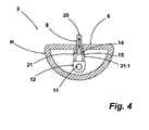
Figur 1 - Fig. 4:
- einen vergrößerten Querschnitt des Armes mit dem Haar- klemmelement des Haarformgerätes der
Figur 1
- Fig. 1:
- 4 is a partially sectioned longitudinal sectional view of a hair styling device with two arms connected to one another in an articulated manner, one arm of which has a hair clamping element,
- Fig. 2:
- an enlarged view of the lower arm of the hair styling of the
FIG. 1 with the hair clamp in its non-use position, - 3:
- an enlarged view of the lower arm of the hair styling of the
FIG. 1 with the hair-clamping element in its position of use, and - 4:
- an enlarged cross section of the arm with the Haarklemmelement the hair styling device of
FIG. 1 ,
Ein als Straightener und Lockenstab ausgelegtes Haarformgerät 1 verfügt über zwei gelenkig zueinander angeordnete, zangenartig gegeneinander verstellbare Arme 2, 3 Die beiden Arme sind jeweils an ein Gelenkteil 4 angeschlossen, welches die Zangen- bzw. scherenartige Bewegung der beiden Arme 2, 3 zueinander gestattet. Die Schwenkbarkeit der Arme 2, 3 gegeneinander ist in
Die Haarformflächen H der beiden Arme 2, 3 weisen, wie auch aus
Zum Unterstützen der Haarsträhnenklemmung innerhalb des Haarformspaltes 7 verfügt der in
Der Übersicht halber sind die beiden bei dem dargestellten Ausführungsbeispiel in den Arm 3 integrierten Heizelemente nicht dargestellt.For clarity, the two integrated in the illustrated embodiment in the
In seine Gebrauchsstellung wird das Haarklemmelement 8 gebracht, indem die in
Zum Drehen einer Locke wird, wie bereits vorbeschrieben, eine Haarsträhne in den Haarformspalt 7 eingelegt und durch Schließen der beiden Arme 2, 3 gegeneinander erfasst. Zuvor ist das Haarklemmelement 8 in seine in
Die Querschnittdarstellung der
Die Erfindung ist anhand eines Ausführungsbeispiels unter Bezugnahme auf die beigefügten Figuren beschrieben worden. Ohne den Umfang der Ansprüche zu verlassen, ergeben sich für einen Fachmann zahlreiche weitere Ausgestaltungen, die Erfindung zu verwirklichen, ohne dass dieses im Einzelnen an dieser Stelle dargelegt werden müsste. So erschließen sich einem Fachmann beispielsweise auch andere Antriebsmechanismen als in dem Ausführungsbeispiel gezeigt. Gleichermaßen ist es möglich, ein Haarformgerät zu konzipieren, dessen beide Arme jeweils ein Haarklemmelement aufweisen. Diese können einander ergänzend dergestalt konzipiert sein, dass die Klemmfläche des einen Haarklemmelementes eine Aufnahme zum Eindrücken von Haar durch das Haarklemmelementes des anderen Arms aufweist. Durch diese Maßnahme kann das Haar besonders wirksam in dem Haarformspalt zwischen den beiden Armen verklemmt werden. Bei dieser Ausgestaltung sind die Haarklemmelemente der beiden Arme fluchtend miteinander angeordnet. Gleichermaßen ist es möglich, bei einer solchen Ausgestaltung die Haarklemmelemente versetzt zueinander anzuordnen oder auch dem einen Arm zwei mit Abstand zueinander angeordnete leistenförmige Haarklemmelemente zuzuordnen und dem anderen Arm ein zwischen diesen beiden Haarklemmelementen angeordnetes Haarklemmelement.The invention has been described with reference to an embodiment with reference to the accompanying figures. Without departing from the scope of the claims, numerous other embodiments will be apparent to those skilled in the art to accomplish the invention without this having to be specifically stated at this point. For example, other drive mechanisms than those shown in the exemplary embodiment will become apparent to a person skilled in the art. Similarly, it is possible to design a hair styling device, both arms of which each have a hair clamp. These can be designed to complement each other in such a way that the clamping surface of a hair-clamping element has a receptacle for pressing hair through the hair-clamping element of the other arm. By this measure, the hair can be particularly effectively clamped in the hair styling gap between the two arms. In this embodiment, the hair-clamping elements of the two arms are arranged in alignment with each other. Similarly, it is possible in such an embodiment, the hair clamp elements offset from each other to order or the one arm two at a distance from each other Assign arranged strip-shaped hair clamp and the other arm arranged between these two hair clamps hair clamp.
- 11
- HaarformgerätThe hair styling appliance
- 22
- Armpoor
- 33
- Armpoor
- 44
- Gelenkteiljoint part
- 55
- HaarformflächenbereichHair styling area
- 66
- HaarformflächenbereichHair styling area
- 77
- HaarformspaltHair styling gap
- 88th
- HaarklemmelementHair clamping element
- 99
- Antriebdrive
- 1010
- Drehknopfknob
- 1111
- Gewindespindelscrew
- 1212
- Muttermother
- 1313
- Halteelementretaining element
- 1414
- Stiftpen
- 1515
- StellschrägeDeputy slope
- 16. 16.116. 16.1
- Federelementspring element
- 17, 17.117, 17.1
- Sicherungsstiftsafety pin
- 18, 18.118, 18.1
- Fußfoot
- 1919
- Schlitzslot
- 2020
- Klemmflächeclamping surface
- 21, 21.121, 21.1
- Armpoor
- HH
- HaarformflächeHair-form surface
Claims (13)
- Hair styling device with two plier-like arms (2, 3) arranged in an articulated manner to each other and moveable in a plier-like manner towards each other, wherein each arm (2, 3) has a hair styling surface (5, H), which is made such that it interacts at least partially with one hair styling surface (6, H) of the other arm (2, 3) for a hair styling process, characterised in that at least one of the two plier-like arms (3) has, integrated in its hair styling surface (H), a hair clamping element (8) moveable towards the hair styling surface (H) of the other arm (2), adjustable into an operational position for using the hair styling device (1) as curling tongs and into a non-operational position for using the hair styling device (1) as straighteners, wherein the hair clamping element (8) in its operational position is held in a projecting position by the force of at least one spring element (16, 16.1) from the hair styling surface (6, H) of this arm (3) in the direction of the other arm (2) and in the non-operational position is lowered against the hair styling surface (6, H).
- Hair styling device according to claim 1, characterised in that the surface (20) pointing in the direction of the other arm (2), of the hair clamping element (8) corresponds to only one fraction of the surface of the hair styling surface (6) of the plier-like arms (3), in which the hair clamping element is integrated.
- Hair styling device according to claim 1 or 2, characterised in that the hair clamping element (8) is mounted moveably perpendicular to the hair styling surface (6).
- Hair styling device according to any one of claims 1 to 3, characterised in that the hair clamping element (8) extends in a longitudinal way and is arranged with its longitudinal extension parallel to the longitudinal axis of the arm (3).
- Hair styling device according to any one of claims 1 to 4, characterised in that the hair clamping element (8) is mounted in a floating manner in its operational position.
- Hair styling device according to claim 5, characterised in that the other arm serving as a counter-bearing for the hair clamping element of the one arm, in the area of its hair styling surface, has a recess into which hair can be pressed with the hair clamping element, which is in its operational position, of the other arm.
- Hair styling device according to any one of claims 1 to 6, characterised in that an actuation mechanism is assigned to the arm supporting the hair clamping element, and with said mechanism the hair clamping element can be brought out of its non-operational position into its operational position.
- Hair styling device according to claim 7, characterised in that the actuation mechanism is embodied as a mechanical drive (9) and the hair clamping element in its operational position is disconnected from the drive.
- Hair styling device according to claim 8, characterised in that the drive (9) has a threaded spindle (11) and a nut (12) as the output drive element, and to said nut (12) a holding element (13) is connected which is in an operative connection to move the hair clamping element (8) from its operational position into its non-operational position.
- Hair styling device according to claim 9, characterised in that the holding element (13) has an adjusting chamfer (15) on which a pin (14) assigned to the hair clamping element (8) lies.
- Hair styling device according to any one of claims 1 to 10, characterised in that in the hair styling surface of the other arm of the hair styling device too, a hair clamping element according to one of claims 1 to 8 is integrated.
- Hair styling device according to claim 11, characterised in that the hair clamping elements of the two plier-like arms are arranged offset from each other.
- Hair styling device according to claim 11, characterised in that the hair clamping element of the one arm has a recess into which hair can be pressed when using the hair styling device with the hair clamping elements in its operational position.
Applications Claiming Priority (1)
| Application Number | Priority Date | Filing Date | Title |
|---|---|---|---|
| DE200920004759 DE202009004759U1 (en) | 2009-04-29 | 2009-04-29 | The hair styling appliance |
Publications (2)
| Publication Number | Publication Date |
|---|---|
| EP2245953A1 EP2245953A1 (en) | 2010-11-03 |
| EP2245953B1 true EP2245953B1 (en) | 2013-08-14 |
Family
ID=42352020
Family Applications (1)
| Application Number | Title | Priority Date | Filing Date |
|---|---|---|---|
| EP20100161027 Not-in-force EP2245953B1 (en) | 2009-04-29 | 2010-04-26 | Hair styling device |
Country Status (4)
| Country | Link |
|---|---|
| EP (1) | EP2245953B1 (en) |
| CN (1) | CN101919614B (en) |
| DE (1) | DE202009004759U1 (en) |
| HK (1) | HK1144362A1 (en) |
Families Citing this family (8)
| Publication number | Priority date | Publication date | Assignee | Title |
|---|---|---|---|---|
| FR2961667B1 (en) * | 2010-06-25 | 2012-08-17 | Seb Sa | HAIRDRESSING APPARATUS WITH JAWS |
| DE102011077138A1 (en) * | 2011-06-07 | 2012-12-13 | BSH Bosch und Siemens Hausgeräte GmbH | hair straightener |
| DE102011078562A1 (en) * | 2011-07-01 | 2013-01-03 | BSH Bosch und Siemens Hausgeräte GmbH | Heated hair styling device |
| RU2641873C2 (en) * | 2012-12-18 | 2018-01-22 | Конинклейке Филипс Н.В. | Hair straightener |
| FR3010284B1 (en) * | 2013-09-11 | 2017-03-24 | Seb Sa | HAIRSTYLE APPARATUS WITH ADJUSTABLE BRUSHES. |
| DE202014104224U1 (en) | 2014-09-08 | 2014-10-16 | Seb S.A. | Hairdressing device with adjustable brushes |
| DE102014221922B4 (en) * | 2014-10-28 | 2022-05-19 | BSH Hausgeräte GmbH | hair styling device |
| FR3076189B1 (en) * | 2017-12-29 | 2021-09-10 | Seb Sa | IMPROVED CINEMATIC STYLING DEVICE |
Family Cites Families (6)
| Publication number | Priority date | Publication date | Assignee | Title |
|---|---|---|---|---|
| DE19750119A1 (en) * | 1997-11-13 | 1999-05-27 | Braun Gmbh | Hair forming appliance |
| JP2006334109A (en) * | 2005-06-01 | 2006-12-14 | Matsushita Electric Works Ltd | Hair setting apparatus |
| DE102005027984A1 (en) * | 2005-06-16 | 2006-12-28 | Braun Gmbh | Harr form unit |
| US7445012B2 (en) * | 2006-04-12 | 2008-11-04 | Takashi Mukai | Hair iron |
| JP4293211B2 (en) * | 2006-08-31 | 2009-07-08 | パナソニック電工株式会社 | Hair iron |
| FR2913317B1 (en) * | 2007-03-07 | 2011-02-11 | Seb Sa | HAIRSTYLING APPARATUS |
-
2009
- 2009-04-29 DE DE200920004759 patent/DE202009004759U1/en not_active Expired - Lifetime
-
2010
- 2010-04-26 EP EP20100161027 patent/EP2245953B1/en not_active Not-in-force
- 2010-04-29 CN CN201010253584.5A patent/CN101919614B/en not_active Expired - Fee Related
- 2010-11-25 HK HK10110953.2A patent/HK1144362A1/en not_active IP Right Cessation
Also Published As
| Publication number | Publication date |
|---|---|
| CN101919614B (en) | 2014-05-21 |
| CN101919614A (en) | 2010-12-22 |
| EP2245953A1 (en) | 2010-11-03 |
| DE202009004759U1 (en) | 2010-09-23 |
| HK1144362A1 (en) | 2011-02-18 |
Similar Documents
| Publication | Publication Date | Title |
|---|---|---|
| EP2245953B1 (en) | Hair styling device | |
| EP2048985B1 (en) | Hair styling apparatus having a guide device, and method for hair styling | |
| EP2305061B1 (en) | Hair straightening device | |
| EP1030571B1 (en) | Hair-styling appliance | |
| DE112013006050T5 (en) | hair straightener | |
| EP1334670A2 (en) | Heated hair styling apparatus as well as hair grooming element formed as attachment | |
| EP3139788B1 (en) | Hair styling appliance | |
| DE202013105507U1 (en) | The hair styling appliance | |
| DE202008016618U1 (en) | Hair styling attachment and hair styling device with such an attachment | |
| EP2181618B1 (en) | Heatable hairstyling apparatus with rotatable gripping tip | |
| EP0897275B1 (en) | Hair styling device and process | |
| EP1733642B1 (en) | Hair styling appliance | |
| DE3243292C2 (en) | ||
| EP3429420B1 (en) | Hair-styling device for curling or waving hair and method for operating such a hair-styling device | |
| DE202009005270U1 (en) | The hair styling appliance | |
| DE2718187A1 (en) | Electrically heated tongs for hair dressing - have opposed undulating and plane surfaces on tong head mounted on fixed and pivoted arms attached to handle | |
| DE202007007961U1 (en) | The hair styling appliance | |
| EP2636333A1 (en) | Hair treatment apparatus | |
| EP2520190A1 (en) | Hair shaping device | |
| DE202008001677U1 (en) | The hair styling appliance | |
| EP1874150B1 (en) | Hair-styling device | |
| WO2006102995A1 (en) | Hair shaping device | |
| DE102014209927A1 (en) | A hair styling device | |
| EP2533663A1 (en) | Attachment for a hairstyling apparatus | |
| WO2013189787A1 (en) | Curling iron |
Legal Events
| Date | Code | Title | Description |
|---|---|---|---|
| PUAI | Public reference made under article 153(3) epc to a published international application that has entered the european phase |
Free format text: ORIGINAL CODE: 0009012 |
|
| AK | Designated contracting states |
Kind code of ref document: A1 Designated state(s): AT BE BG CH CY CZ DE DK EE ES FI FR GB GR HR HU IE IS IT LI LT LU LV MC MK MT NL NO PL PT RO SE SI SK SM TR |
|
| AX | Request for extension of the european patent |
Extension state: AL BA ME RS |
|
| REG | Reference to a national code |
Ref country code: HK Ref legal event code: DE Ref document number: 1144362 Country of ref document: HK |
|
| 17P | Request for examination filed |
Effective date: 20110415 |
|
| 17Q | First examination report despatched |
Effective date: 20110826 |
|
| REG | Reference to a national code |
Ref country code: DE Ref legal event code: R079 Ref document number: 502010004329 Country of ref document: DE Free format text: PREVIOUS MAIN CLASS: A45D0001040000 Ipc: A45D0001060000 |
|
| RIC1 | Information provided on ipc code assigned before grant |
Ipc: A45D 2/00 20060101ALI20130122BHEP Ipc: A45D 1/04 20060101ALI20130122BHEP Ipc: A45D 1/06 20060101AFI20130122BHEP |
|
| GRAP | Despatch of communication of intention to grant a patent |
Free format text: ORIGINAL CODE: EPIDOSNIGR1 |
|
| INTG | Intention to grant announced |
Effective date: 20130507 |
|
| GRAS | Grant fee paid |
Free format text: ORIGINAL CODE: EPIDOSNIGR3 |
|
| GRAA | (expected) grant |
Free format text: ORIGINAL CODE: 0009210 |
|
| RAP1 | Party data changed (applicant data changed or rights of an application transferred) |
Owner name: WIK FAR EAST LTD. |
|
| AK | Designated contracting states |
Kind code of ref document: B1 Designated state(s): AT BE BG CH CY CZ DE DK EE ES FI FR GB GR HR HU IE IS IT LI LT LU LV MC MK MT NL NO PL PT RO SE SI SK SM TR |
|
| REG | Reference to a national code |
Ref country code: GB Ref legal event code: FG4D Free format text: NOT ENGLISH |
|
| REG | Reference to a national code |
Ref country code: CH Ref legal event code: NV Representative=s name: ALDO ROEMPLER PATENTANWALT, CH Ref country code: CH Ref legal event code: EP Ref country code: AT Ref legal event code: REF Ref document number: 626260 Country of ref document: AT Kind code of ref document: T Effective date: 20130815 |
|
| REG | Reference to a national code |
Ref country code: IE Ref legal event code: FG4D Free format text: LANGUAGE OF EP DOCUMENT: GERMAN |
|
| REG | Reference to a national code |
Ref country code: DE Ref legal event code: R096 Ref document number: 502010004329 Country of ref document: DE Effective date: 20131010 |
|
| REG | Reference to a national code |
Ref country code: HK Ref legal event code: GR Ref document number: 1144362 Country of ref document: HK |
|
| REG | Reference to a national code |
Ref country code: NL Ref legal event code: VDEP Effective date: 20130814 |
|
| REG | Reference to a national code |
Ref country code: LT Ref legal event code: MG4D |
|
| PG25 | Lapsed in a contracting state [announced via postgrant information from national office to epo] |
Ref country code: SE Free format text: LAPSE BECAUSE OF FAILURE TO SUBMIT A TRANSLATION OF THE DESCRIPTION OR TO PAY THE FEE WITHIN THE PRESCRIBED TIME-LIMIT Effective date: 20130814 Ref country code: IS Free format text: LAPSE BECAUSE OF FAILURE TO SUBMIT A TRANSLATION OF THE DESCRIPTION OR TO PAY THE FEE WITHIN THE PRESCRIBED TIME-LIMIT Effective date: 20131214 Ref country code: PT Free format text: LAPSE BECAUSE OF FAILURE TO SUBMIT A TRANSLATION OF THE DESCRIPTION OR TO PAY THE FEE WITHIN THE PRESCRIBED TIME-LIMIT Effective date: 20131216 Ref country code: HR Free format text: LAPSE BECAUSE OF FAILURE TO SUBMIT A TRANSLATION OF THE DESCRIPTION OR TO PAY THE FEE WITHIN THE PRESCRIBED TIME-LIMIT Effective date: 20130814 Ref country code: LT Free format text: LAPSE BECAUSE OF FAILURE TO SUBMIT A TRANSLATION OF THE DESCRIPTION OR TO PAY THE FEE WITHIN THE PRESCRIBED TIME-LIMIT Effective date: 20130814 Ref country code: NO Free format text: LAPSE BECAUSE OF FAILURE TO SUBMIT A TRANSLATION OF THE DESCRIPTION OR TO PAY THE FEE WITHIN THE PRESCRIBED TIME-LIMIT Effective date: 20131114 Ref country code: CY Free format text: LAPSE BECAUSE OF FAILURE TO SUBMIT A TRANSLATION OF THE DESCRIPTION OR TO PAY THE FEE WITHIN THE PRESCRIBED TIME-LIMIT Effective date: 20130710 |
|
| PG25 | Lapsed in a contracting state [announced via postgrant information from national office to epo] |
Ref country code: FI Free format text: LAPSE BECAUSE OF FAILURE TO SUBMIT A TRANSLATION OF THE DESCRIPTION OR TO PAY THE FEE WITHIN THE PRESCRIBED TIME-LIMIT Effective date: 20130814 Ref country code: PL Free format text: LAPSE BECAUSE OF FAILURE TO SUBMIT A TRANSLATION OF THE DESCRIPTION OR TO PAY THE FEE WITHIN THE PRESCRIBED TIME-LIMIT Effective date: 20130814 Ref country code: LV Free format text: LAPSE BECAUSE OF FAILURE TO SUBMIT A TRANSLATION OF THE DESCRIPTION OR TO PAY THE FEE WITHIN THE PRESCRIBED TIME-LIMIT Effective date: 20130814 Ref country code: GR Free format text: LAPSE BECAUSE OF FAILURE TO SUBMIT A TRANSLATION OF THE DESCRIPTION OR TO PAY THE FEE WITHIN THE PRESCRIBED TIME-LIMIT Effective date: 20131115 Ref country code: SI Free format text: LAPSE BECAUSE OF FAILURE TO SUBMIT A TRANSLATION OF THE DESCRIPTION OR TO PAY THE FEE WITHIN THE PRESCRIBED TIME-LIMIT Effective date: 20130814 |
|
| PG25 | Lapsed in a contracting state [announced via postgrant information from national office to epo] |
Ref country code: CY Free format text: LAPSE BECAUSE OF FAILURE TO SUBMIT A TRANSLATION OF THE DESCRIPTION OR TO PAY THE FEE WITHIN THE PRESCRIBED TIME-LIMIT Effective date: 20130814 |
|
| PG25 | Lapsed in a contracting state [announced via postgrant information from national office to epo] |
Ref country code: EE Free format text: LAPSE BECAUSE OF FAILURE TO SUBMIT A TRANSLATION OF THE DESCRIPTION OR TO PAY THE FEE WITHIN THE PRESCRIBED TIME-LIMIT Effective date: 20130814 Ref country code: RO Free format text: LAPSE BECAUSE OF FAILURE TO SUBMIT A TRANSLATION OF THE DESCRIPTION OR TO PAY THE FEE WITHIN THE PRESCRIBED TIME-LIMIT Effective date: 20130814 Ref country code: CZ Free format text: LAPSE BECAUSE OF FAILURE TO SUBMIT A TRANSLATION OF THE DESCRIPTION OR TO PAY THE FEE WITHIN THE PRESCRIBED TIME-LIMIT Effective date: 20130814 Ref country code: SK Free format text: LAPSE BECAUSE OF FAILURE TO SUBMIT A TRANSLATION OF THE DESCRIPTION OR TO PAY THE FEE WITHIN THE PRESCRIBED TIME-LIMIT Effective date: 20130814 Ref country code: NL Free format text: LAPSE BECAUSE OF FAILURE TO SUBMIT A TRANSLATION OF THE DESCRIPTION OR TO PAY THE FEE WITHIN THE PRESCRIBED TIME-LIMIT Effective date: 20130814 Ref country code: DK Free format text: LAPSE BECAUSE OF FAILURE TO SUBMIT A TRANSLATION OF THE DESCRIPTION OR TO PAY THE FEE WITHIN THE PRESCRIBED TIME-LIMIT Effective date: 20130814 |
|
| PG25 | Lapsed in a contracting state [announced via postgrant information from national office to epo] |
Ref country code: ES Free format text: LAPSE BECAUSE OF FAILURE TO SUBMIT A TRANSLATION OF THE DESCRIPTION OR TO PAY THE FEE WITHIN THE PRESCRIBED TIME-LIMIT Effective date: 20130814 Ref country code: IT Free format text: LAPSE BECAUSE OF FAILURE TO SUBMIT A TRANSLATION OF THE DESCRIPTION OR TO PAY THE FEE WITHIN THE PRESCRIBED TIME-LIMIT Effective date: 20130814 |
|
| PLBE | No opposition filed within time limit |
Free format text: ORIGINAL CODE: 0009261 |
|
| STAA | Information on the status of an ep patent application or granted ep patent |
Free format text: STATUS: NO OPPOSITION FILED WITHIN TIME LIMIT |
|
| 26N | No opposition filed |
Effective date: 20140515 |
|
| REG | Reference to a national code |
Ref country code: DE Ref legal event code: R097 Ref document number: 502010004329 Country of ref document: DE Effective date: 20140515 |
|
| PG25 | Lapsed in a contracting state [announced via postgrant information from national office to epo] |
Ref country code: MC Free format text: LAPSE BECAUSE OF FAILURE TO SUBMIT A TRANSLATION OF THE DESCRIPTION OR TO PAY THE FEE WITHIN THE PRESCRIBED TIME-LIMIT Effective date: 20130814 Ref country code: LU Free format text: LAPSE BECAUSE OF FAILURE TO SUBMIT A TRANSLATION OF THE DESCRIPTION OR TO PAY THE FEE WITHIN THE PRESCRIBED TIME-LIMIT Effective date: 20140426 |
|
| REG | Reference to a national code |
Ref country code: CH Ref legal event code: PL |
|
| GBPC | Gb: european patent ceased through non-payment of renewal fee |
Effective date: 20140426 |
|
| REG | Reference to a national code |
Ref country code: FR Ref legal event code: ST Effective date: 20141231 |
|
| REG | Reference to a national code |
Ref country code: IE Ref legal event code: MM4A |
|
| PG25 | Lapsed in a contracting state [announced via postgrant information from national office to epo] |
Ref country code: GB Free format text: LAPSE BECAUSE OF NON-PAYMENT OF DUE FEES Effective date: 20140426 Ref country code: LI Free format text: LAPSE BECAUSE OF NON-PAYMENT OF DUE FEES Effective date: 20140430 Ref country code: CH Free format text: LAPSE BECAUSE OF NON-PAYMENT OF DUE FEES Effective date: 20140430 |
|
| PG25 | Lapsed in a contracting state [announced via postgrant information from national office to epo] |
Ref country code: FR Free format text: LAPSE BECAUSE OF NON-PAYMENT OF DUE FEES Effective date: 20140430 |
|
| PG25 | Lapsed in a contracting state [announced via postgrant information from national office to epo] |
Ref country code: IE Free format text: LAPSE BECAUSE OF NON-PAYMENT OF DUE FEES Effective date: 20140426 |
|
| PGFP | Annual fee paid to national office [announced via postgrant information from national office to epo] |
Ref country code: DE Payment date: 20150313 Year of fee payment: 6 |
|
| PG25 | Lapsed in a contracting state [announced via postgrant information from national office to epo] |
Ref country code: MT Free format text: LAPSE BECAUSE OF FAILURE TO SUBMIT A TRANSLATION OF THE DESCRIPTION OR TO PAY THE FEE WITHIN THE PRESCRIBED TIME-LIMIT Effective date: 20130814 |
|
| PG25 | Lapsed in a contracting state [announced via postgrant information from national office to epo] |
Ref country code: SM Free format text: LAPSE BECAUSE OF FAILURE TO SUBMIT A TRANSLATION OF THE DESCRIPTION OR TO PAY THE FEE WITHIN THE PRESCRIBED TIME-LIMIT Effective date: 20130814 |
|
| REG | Reference to a national code |
Ref country code: AT Ref legal event code: MM01 Ref document number: 626260 Country of ref document: AT Kind code of ref document: T Effective date: 20150426 |
|
| PG25 | Lapsed in a contracting state [announced via postgrant information from national office to epo] |
Ref country code: BG Free format text: LAPSE BECAUSE OF FAILURE TO SUBMIT A TRANSLATION OF THE DESCRIPTION OR TO PAY THE FEE WITHIN THE PRESCRIBED TIME-LIMIT Effective date: 20130814 |
|
| PG25 | Lapsed in a contracting state [announced via postgrant information from national office to epo] |
Ref country code: TR Free format text: LAPSE BECAUSE OF FAILURE TO SUBMIT A TRANSLATION OF THE DESCRIPTION OR TO PAY THE FEE WITHIN THE PRESCRIBED TIME-LIMIT Effective date: 20130814 Ref country code: BE Free format text: LAPSE BECAUSE OF FAILURE TO SUBMIT A TRANSLATION OF THE DESCRIPTION OR TO PAY THE FEE WITHIN THE PRESCRIBED TIME-LIMIT Effective date: 20140430 Ref country code: HU Free format text: LAPSE BECAUSE OF FAILURE TO SUBMIT A TRANSLATION OF THE DESCRIPTION OR TO PAY THE FEE WITHIN THE PRESCRIBED TIME-LIMIT; INVALID AB INITIO Effective date: 20100426 |
|
| PG25 | Lapsed in a contracting state [announced via postgrant information from national office to epo] |
Ref country code: AT Free format text: LAPSE BECAUSE OF NON-PAYMENT OF DUE FEES Effective date: 20150426 |
|
| REG | Reference to a national code |
Ref country code: DE Ref legal event code: R119 Ref document number: 502010004329 Country of ref document: DE |
|
| PG25 | Lapsed in a contracting state [announced via postgrant information from national office to epo] |
Ref country code: DE Free format text: LAPSE BECAUSE OF NON-PAYMENT OF DUE FEES Effective date: 20161101 |
|
| PG25 | Lapsed in a contracting state [announced via postgrant information from national office to epo] |
Ref country code: MK Free format text: LAPSE BECAUSE OF FAILURE TO SUBMIT A TRANSLATION OF THE DESCRIPTION OR TO PAY THE FEE WITHIN THE PRESCRIBED TIME-LIMIT Effective date: 20130814 |