EP2245517B1 - Bedienelement mit verbesserter kipphaptik - Google Patents
Bedienelement mit verbesserter kipphaptik Download PDFInfo
- Publication number
- EP2245517B1 EP2245517B1 EP08871105.6A EP08871105A EP2245517B1 EP 2245517 B1 EP2245517 B1 EP 2245517B1 EP 08871105 A EP08871105 A EP 08871105A EP 2245517 B1 EP2245517 B1 EP 2245517B1
- Authority
- EP
- European Patent Office
- Prior art keywords
- force
- permanent magnet
- control element
- lever arm
- magnets
- Prior art date
- Legal status (The legal status is an assumption and is not a legal conclusion. Google has not performed a legal analysis and makes no representation as to the accuracy of the status listed.)
- Active
Links
- 239000004020 conductor Substances 0.000 claims description 11
- 238000006073 displacement reaction Methods 0.000 claims description 11
- 230000007423 decrease Effects 0.000 claims description 6
- 238000010586 diagram Methods 0.000 description 6
- 230000015572 biosynthetic process Effects 0.000 description 3
- 239000000463 material Substances 0.000 description 2
- 238000000418 atomic force spectrum Methods 0.000 description 1
- 230000001939 inductive effect Effects 0.000 description 1
- 239000002655 kraft paper Substances 0.000 description 1
- 239000000696 magnetic material Substances 0.000 description 1
- 230000008092 positive effect Effects 0.000 description 1
- 229910000938 samarium–cobalt magnet Inorganic materials 0.000 description 1
Images
Classifications
-
- G—PHYSICS
- G05—CONTROLLING; REGULATING
- G05G—CONTROL DEVICES OR SYSTEMS INSOFAR AS CHARACTERISED BY MECHANICAL FEATURES ONLY
- G05G5/00—Means for preventing, limiting or returning the movements of parts of a control mechanism, e.g. locking controlling member
- G05G5/05—Means for returning or tending to return controlling members to an inoperative or neutral position, e.g. by providing return springs or resilient end-stops
-
- G—PHYSICS
- G05—CONTROLLING; REGULATING
- G05G—CONTROL DEVICES OR SYSTEMS INSOFAR AS CHARACTERISED BY MECHANICAL FEATURES ONLY
- G05G9/00—Manually-actuated control mechanisms provided with one single controlling member co-operating with two or more controlled members, e.g. selectively, simultaneously
- G05G9/02—Manually-actuated control mechanisms provided with one single controlling member co-operating with two or more controlled members, e.g. selectively, simultaneously the controlling member being movable in different independent ways, movement in each individual way actuating one controlled member only
- G05G9/04—Manually-actuated control mechanisms provided with one single controlling member co-operating with two or more controlled members, e.g. selectively, simultaneously the controlling member being movable in different independent ways, movement in each individual way actuating one controlled member only in which movement in two or more ways can occur simultaneously
- G05G9/047—Manually-actuated control mechanisms provided with one single controlling member co-operating with two or more controlled members, e.g. selectively, simultaneously the controlling member being movable in different independent ways, movement in each individual way actuating one controlled member only in which movement in two or more ways can occur simultaneously the controlling member being movable by hand about orthogonal axes, e.g. joysticks
- G05G2009/04766—Manually-actuated control mechanisms provided with one single controlling member co-operating with two or more controlled members, e.g. selectively, simultaneously the controlling member being movable in different independent ways, movement in each individual way actuating one controlled member only in which movement in two or more ways can occur simultaneously the controlling member being movable by hand about orthogonal axes, e.g. joysticks providing feel, e.g. indexing means, means to create counterforce
-
- Y—GENERAL TAGGING OF NEW TECHNOLOGICAL DEVELOPMENTS; GENERAL TAGGING OF CROSS-SECTIONAL TECHNOLOGIES SPANNING OVER SEVERAL SECTIONS OF THE IPC; TECHNICAL SUBJECTS COVERED BY FORMER USPC CROSS-REFERENCE ART COLLECTIONS [XRACs] AND DIGESTS
- Y10—TECHNICAL SUBJECTS COVERED BY FORMER USPC
- Y10T—TECHNICAL SUBJECTS COVERED BY FORMER US CLASSIFICATION
- Y10T74/00—Machine element or mechanism
- Y10T74/20—Control lever and linkage systems
- Y10T74/20576—Elements
- Y10T74/20582—Levers
Definitions
- the present invention relates to a control element for a motor vehicle, in particular a multi-directional tilting joystick, with a control knob, located in a housing of the control element bearing for the control knob, a permanently connected to the control knob extension, attached to the extension first permanent magnet and a fixed in the housing second permanent magnet, wherein the permanent magnets form a pair of permanent magnets and in a central position of the control knob unequal poles of the magnets are spaced from each other.
- Tilting controls are used in motor vehicles where several functions can be performed by means of a control element. Examples include toggle switches for power windows or electrically adjustable exterior mirrors and joystick-like controls for controlling an on-board computer.
- joystick-type operating elements are understood as meaning such operating elements which can be tilted at least in four directions, so that a menu in a display system assigned to the operating element can be activated by means of the joystick-type operating element.
- a force variable over the deflection is necessary for the operation of the operating element, via which the user is informed that the switching operation has taken place.
- this force-displacement curve is usually generated by one or more springs or cooperating permanent magnets, which also bring the control back to a middle position when the user lets go.
- the control element has a tiltably mounted lever with a primary and at least one secondary lever arm and at least one pair of permanent magnets, wherein a magnet of a pair of permanent magnets on a secondary lever arm and a magnet is arranged stationarily in the control element.
- unequal poles of the magnets face each other in such a way that the operating element is held in a middle position.
- the force curve over the deflection of the control element depends on the parameters: length of the secondary lever arm, strength of the permanent magnets, physical size of the permanent magnets and the size of the air gap between the magnets of a permanent magnet pair.
- the document DE 4109544 discloses a known operating element.
- the object of the invention is to change the feel of a control element such that the force-displacement curve, that is, the feel of the control element is selectively adjustable, and this can be realized with minimal design effort and cost.
- the object of the invention is achieved in that at least partially and / or circumferentially a magnetically conductive material is attached to a arranged in the control element permanent magnet pair.
- the permanent magnet pairs are surrounded in a flat, embodiment of the permanent magnets with a conductive material.
- the outer magnetic field lines are more or less concentrated depending on the strength and magnetic conductivity of the sheath.
- the casing consists in the inventive form of electrically conductive materials or rare earths, such as Sm 2 Co 17 , SmCo 2 or NdFeW.
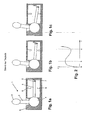
- the Figures 1 a, 1b and 1 c show a side view in section of a control element 1 in three different operating positions, according to the prior art.
- the housing 9 of the control element 1 has a recess in which a ball is arranged as a bearing for a lever.
- the lever consists of a primary lever arm 2 and a secondary lever arm 9. One end of the lever arm 2 is fixedly connected to the ball 4, the other end carries a handle 3, in the form of a control knob.
- the secondary lever arm 5 is fixedly connected at one end to the ball 4, the other end carries a permanent magnet 6.
- a second permanent magnet 7 is arranged in the housing 9, that in the middle position of the primary lever arm 2, an air gap between the magnet 6 and the Magnets 7 is made and opposite poles of the magnets are opposite.
- the end stops 8 limit the range of motion of the secondary lever arm 5 and thus also of the primary lever arm second
- FIG. 1b shows the control element 1 with slightly deflected primary lever arm 2, wherein in the FIG. 1b shown position of the dashed line b from the force-displacement diagram of FIG. 2 equivalent.
- the tilting movement of the primary lever arm 2 is transmitted to the secondary lever arm 5.
- This movement of the lever arm 5 has a relative movement of the magnets 6 and 7 result.
- the in FIG. 1b shown position of the lever is the force that is necessary for further tilting of the lever, greater than the force required to tilt the lever from the in FIG. 1a outlined position is necessary.
- the in FIG. 1b illustrated deflection of the lever is the repulsive force between the north poles of the magnets 6 and 7 of the attractive force of the unequal poles of the magnets 6 and 7 directed against. This means that the force to be applied by the user to further tilt the lever decreases.
- This decrease in the restoring force gives the user a haptic feedback that the switching operation has taken place, wherein the decrease of the force from the position B to the position C in the FIG. 2 is called a snap.
- the drop in force or snap equals about one third of the maximum force that the user has to apply.
- the end stop 8 causes via the secondary lever arm 5 and the ball 4 is a limitation of Kippweges the primary lever arm 2.
- the end stop 8 is designed to be elastic, to prevent a sudden increase in drag force. Due to the low compliance of the material of the end stop is a fast but steady increase in drag, as in the outlet of the curve in FIG. 2 is shown.
- FIG. 3a are the permanent magnet pairs 6 and 7 detached from the control element 1 shown.
- the permanent magnet pairs consist of a north pole (dark gray) and a south pole (light gray). Opposite poles of the magnets thus have a different polarity, so that the handle 3 or the control knob 3 is held in its center position.
- the magnets are flat and formed at their opposite ends 10, 11, for example, square or rectangular.
- FIG. 3b shows a permanent magnet pair 12, 13 with arranged on both sides of the magnets 12,13 sheets 14, 15, 16, 17 of a magnetic field lines conductive material.
- the sheets 14, 15, 16, 17 or conductive pads 14, 15, 16, 17 cause an alignment and bundling of the magnets 12, 13 surrounding magnetic field lines 18.
- the alignment and bundling of the magnetic field lines 18 according to the invention allows an increase in the maximum force F, without the use of expensive and bulky permanent magnets.
- material, thickness and number of sheets 14, 15, 16, 17 on the circumference of the permanent magnets 12, 13 is thus a targeted control of the force-displacement curve and consequently the haptic on the control possible.
- an advantage of the invention is that, while maintaining the maximum force, an increase in the air gap 19 between the permanent magnets 12, 13 is made possible, which in turn facilitates the assembly.
- the permanent magnets 12, 13 are made flat, so that the magnetically conductive sheets can be fastened flat at the lateral ends of the permanent magnets 12, 13.
- the permanent magnets 12, 13 are made flat, so that the magnetically conductive sheets can be fastened flat at the lateral ends of the permanent magnets 12, 13.
- the permanent magnets 12, 13 as circular permanent magnets 12, 13, it is then conceivable to surround the permanent magnets 12, 13 completely and circumferentially with a magnetically conductive material.
- the complete sheathing of the permanent magnets 12, 13 is also executable with flat permanent magnets 12, 13.
- F1 as well as the path S3 varies depending on the application and the haptics to be set or predetermined.
- a path of S3 1.5 mm can be specified for the path S3.
- the point of repulsion between the permanent magnets 12, 13 is not reached, so that the control knob automatically moves back to its center position automatically after actuation.
- the S1 path can be specified with 45 percent of S3 and a tolerance of plus 5% and minus 10%.
- the control element 20 has a primary lever arm 21, for receiving a control knob, not shown, a bearing 22 in the form of a spherical bearing 22, a secondary lever arm 23, wherein primary and secondary lever arm 21, 23 in a center line or central axis 24 are arranged one above the other in alignment ,
- boom 25, 26 are attached.
- a permanent magnet 27 is fixed, which cooperates with a permanent magnet 28, wherein the permanent magnet 28 is fixed in a fixed to the housing of the control element 20 connected or forming part of the housing bottom part 29 of the control element 20.
- the permanent magnets 27, 28 form a permanent magnet pair 27, 28, wherein the opposite poles of.
- Permanent magnets 27, 28 differ, so that the lever arms 21, 23 are held in a central position.
- two jibs 26, each with a permanent magnet pair 27, 28 in the operating element 20 offset by 90 degrees in the control element 20 are installed.
- the boom 25 is offset by 180 degrees attached to the secondary lever arm 23.
- the boom 25 cooperates with means for detecting the position and for detecting the path F of the deflection of the lever 23. It is conceivable, for example, the use of photosensitive or inductive sensors.
- two extension arms 25 are also arranged offset by 90 degrees on the secondary lever arm 23.
- the magnetically conductive materials according to the invention such as sheets
- the magnetically conductive materials according to the invention such as soft magnetic materials, electrical sheets or rare earths on the permanent magnets 27, 28, the field lines are bundled, so that the maximum force can be increased by 50% to 100%.
- the formation of the elastic end stop 31 in the bottom part 29 of the operating element 20 can also be used as a slide guide 31.
- the elastic element 31 would, for example, have a cross-groove 32 in which the pin 30 is guided.
- a slotted guide is only conditionally necessary, since by the use of magnetically conductive materials around the permanent magnets 27, 28 ensure adequate guidance.
- the use of permanent magnet pairs is also suitable for the use of push buttons.
- an extension is attached to the control knob in one piece or at least non-positively, wherein a first permanent magnet is attached to the extension.
- a second permanent magnet is fixed, wherein the permanent magnets form a pair of permanent magnets and spaced apart in an initial position of the control knob of the pushbutton unequal poles of the magnets and to the permanent magnet pairs in addition a magnetic field lines conductive material is attached.
- the force-displacement curve of a pushbutton essentially corresponds to that of a joystick-type operating element (20), wherein only the control button and the extension execute a linear movement in the direction of the operating element.
Description
- Die vorliegende Erfindung betrifft ein Bedienelement für ein Kraftfahrzeug insbesondere einen in mehreren Richtungen kippbaren Joystick, mit einem Bedienknopf, einer in einem Gehäuse des Bedienelementes befindlichen Lagerstelle für den Bedienknopf, einer fest mit dem Bedienknopf verbundenen Verlängerung, einem an der Verlängerung befestigten ersten Permanentmagneten und einem im Gehäuse befestigten zweiten Permanentmagneten, wobei die Permanentmagnete ein Permanentmagnetpaar bilden und sich in einer Mittelstellung des Bedienknopfes ungleiche Pole der Magnete beabstandet gegenüber stehen.
- Kippbare Bedienelemente werden in Kraftfahrzeugen dort eingesetzt, wo mittels eines Bedienelementes mehrere Funktionen ausführbar sind. Beispiele dafür sind Kippschalter für elektrische Fensterheber oder elektrisch verstellbare Außenspiegel sowie joystickartige Bedienelemente zur Steuerung eines Bordcomputers. Hierbei werden unter joystickartigen Bedienelementen derartige Bedienelemente verstanden, die zumindest in vier Richtungen kippbar sind, so dass mittels des joystickartigen Bedienelementes ein Menü in einem dem Bedienelement zugeordneten Anzeigesystem ansteuerbar ist. Für eine angenehmere Bedienung und zur haptischen Rückmeldung der Betätigung ist zur Bedienung des Bedienelementes eine über die Auslenkung veränderliche Kraft notwendig, über die dem Benutzer vermittelt wird, dass der Schaltvorgang erfolgt ist. Bei den bekannten Bedienelementen wird dieser Kraft-Weg-Verlauf üblicherweise durch eine oder mehrere Federn oder kooperierende Permanentmagnete erzeugt, die zusätzlich das Bedienelement in eine Mittelstellung zurückbringen, wenn es der Benutzer loslässt.
- Aus der
DE 10 2006 002 634 A1 ist ein Bedienelement, insbesondere ein Joystick mit einer Kipphaptik für ein Kraftfahrzeug bekannt. Das Bedienelement weist einen kippbar gelagerten Hebel mit einem primären und mindestens einem sekundären Hebelarm sowie mindestens ein Permanentmagnetenpaar auf, wobei ein Magnet eines Permanentmagnetenpaares an einem sekundären Hebelarm und ein Magnet ortsfest im Bedienelement angeordnet ist. Hierbei stehen sich ungleiche Pole der Magnete derart gegenüber, dass das Bedienelement in einer Mittelstellung gehalten ist. Der Kraftverlauf über die Auslenkung des Bedienelementes hängt dabei ab von den Parametern: Länge des sekundären Hebelarms, Stärke der Permanentmagnete, physikalische Größe der Permanentmagnete und die Größe des Luftspalts zwischen den Magneten eines Permanentmagnetenpaares. Durch die Kraft zwischen den Magneten wird der sekundäre Hebelarm und damit der gesamte Hebel in der Mittelstellung gehalten. Zum Kippen des primären Hebelarms muss der Benutzer eine Kraft überwinden. Die Gegenkraft, die der Benutzer zum Kippen des primären Hebelarms überwinden muss, ist graphisch darstellbar, wobei nach einer Überwindung eines Kraftmaximums die Kraft zur Auslenkung des Hebels wieder abnimmt und schließlich nach einem Erreichen eines Endanschlags erneut ansteigt. Der Verlauf des für den Bediener des Bedienelementes fühlbaren Kraftanstiegs, Kraftabfalls und erneuten Kraftanstiegs wird hierbei als Haptik des Bedienelementes bezeichnet. - Das Dokument
DE 4109544 offenbart ein bekanntes Bedienelement. - Die Aufgabe der Erfindung ist es, die Haptik eines Bedienelementes derart zu verändern, dass der Kraft-Weg-Verlauf, das heißt die Haptik des Bedienelementes gezielt einstellbar ist, wobei dies mit minimalem konstruktivem Aufwand und kostengünstig zu realisieren ist.
- Die erfindungsgemäße Aufgabe wird dadurch gelöst, dass an einem in dem Bedienelement angeordneten Permanentmagnetenpaar zumindest bereichsweise und/oder umfänglich ein magnetisch leitfähiger Werkstoff befestigt ist. Durch die erfindungsgemäße Ausbildung eines Bedienelementes ist nun die Möglichkeit geschaffen, vorhandene Bedienelemente mit minimalem konstruktivem Aufwand und somit kostengünstig in ihrem Haptikverlauf entscheidend zu beeinflussen. So ist es insbesondere ohne eine Veränderung der vorhandenen Magnete möglich, den Haptikverlauf in Bezug auf die Maximalkraft und den Weg zur Erreichung dieses Maximalkraftwertes gezielt zu beeinflussen. Es ist insbesondere möglich, die Höhe der Maximalkraft und somit das Moment am Bedienelement zu variieren, ohne die Stärke der Permanentmagnete oder deren physikalische Größe zu verändern. Es ist weiterhin die Möglichkeit geschaffen, mit minimal konstruktivem Aufwand und unter Beibehaltung der geometrischen Abmessungen vorhandener Permanentmagnetenpaare den Kraft-Weg-Verlauf der Haptik wesentlich zu beeinflussen.
- Die Permanentmagnetenpaare sind in einer flachen, Ausführungsform der Permanentmagnete mit einem leitfähigen Werkstoff umgeben. In der Ummantelung beziehungsweise seitlichen Ergänzung der Permanentmagnete werden die äußeren magnetischen Feldlinien je nach Stärke und magnetischer Leitfähigkeit der Ummantelung mehr oder weniger stark gebündelt.
- Die Ummantelung besteht in der erfindungsgemäßen Form aus elektrisch-leitfähigen Werkstoffen oder seltenen Erden, wie beispielsweise Sm2Co17, SmCo2 oder NdFeW.
- Nachfolgend wird die Erfindung anhand von Diagrammen und Skizzen an Ausführungsbeispielen erläutert. Es zeigen:
- Figur 1
- ein aus dem Stand der Technik bekanntes joystickartiges Bedienelement,
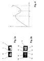
- Figur 2
- ein Kraft-Weg-Diagramm als haptischen Verlauf der Kraft-Weg-Linie des Bedienelementes gemäß der
Figur 1 , - Figur 3a
- die Anordnung eines Permanentmagnetenpaares gemäß dem Stand der Technik,
- Figur 3b
- die Ausbildung eines erfindungsgemäßen Permanentmagnetenpaares in einem Bedienelement,
- Figur 4
- den haptischen Verlauf eines Bedienelementes als Funktion von Kraft und Weg und
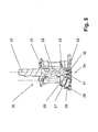
- Figur 5
- ein Ausführungsbeispiel eines erfindungsgemäßen Bedienelementes
- Die
Figuren 1 a, 1b und 1 c zeigen eine Seitenansicht im Schnitt eines Bedienelementes 1 in drei verschiedenen Bedienpositionen, nach dem Stand der Technik. Das Gehäuse 9 des Bedienelementes 1 weist eine Ausnehmung auf, in der eine Kugel als Lagerstelle für einen Hebel angeordnet ist. Der Hebel besteht aus einem primären Hebelarm 2 und einem sekundären Hebelarm 9. Ein Ende des Hebelarms 2 ist fest mit der Kugel 4 verbunden, das andere Ende trägt eine Handhabe 3, in Form eines Bedienknaufs. Der sekundäre Hebelarm 5 ist mit einem Ende fest mit der Kugel 4 verbunden, das andere Ende trägt einen Permanentmagneten 6. Ein zweiter Permanentmagnet 7 ist derart im Gehäuse 9 angeordnet, dass in der Mittelstellung des primären Hebelarms 2 ein Luftspalt zwischen dem Magneten 6 und dem Magneten 7 besteht und sich ungleiche Pole der Magnete gegenüber stehen. Die Endanschläge 8 begrenzen den Bewegungsspielraum des sekundären Hebelarms 5 und damit ebenfalls des primären Hebelarms 2. - Durch die Kraft zwischen den Magneten 6 und 7 wird der sekundäre Hebelarm 5 und damit der gesamte Hebel in der Mittelstellung gehalten. Zum Kippen des primären Hebelarms muss der Benutzer diese Kraft überwinden. Die Kraft F oder Gegenkraft, die der Benutzer zum weiteren Kippen des primären Hebelarms überwinden muss, ist in der
Figur 2 über die Auslenkung s des primären Hebelarms 2 aufgetragen. Die Schnittdarstellung inFigur 1b zeigt das Bedienelement 1 mit leicht ausgelenktem primärem Hebelarm 2, wobei die in derFigur 1b dargestellte Position der gestrichelten Linie b aus dem Kraft-Weg-Diagramm derFigur 2 entspricht. Über die Kugel 4 wird die Kippbewegung des primären Hebelarms 2 auf den sekundären Hebelarm 5 übertragen. Diese Bewegung des Hebelarms 5 hat eine Relativbewegung der Magnete 6 und 7 zur Folge. In der inFigur 1b dargestellten Position des Hebels ist die Kraft, die zum weiteren Kippen des Hebels notwendig ist, größer als die Kraft, die zum Kippen des Hebels aus der inFigur 1a dargestellten Position heraus notwendig ist. Aber der inFigur 1b dargestellten Auslenkung des Hebels ist die abstoßende Kraft zwischen den Nordpolen der Magnete 6 und 7 der anziehenden Kraft der ungleichen Pole der Magnete 6 und 7 entgegen gerichtet. Dies bedeutet, dass die von dem Benutzer aufzubringende Kraft, um den Hebel weiter zu kippen, abnimmt. Diese Abnahme der Rückstellkraft gibt dem Benutzer eine haptische Rückmeldung darüber, dass der Schaltvorgang erfolgt ist, wobei die Abnahme der Kraft von der Position B zur Position C in derFigur 2 als Snap bezeichnet wird. Im Idealfall entspricht der Abfall der Kraft oder der Snap etwa einem Drittel der Maximalkraft, die vom Benutzer aufzubringen ist. - In der in
Figur 1c dargestellten Position des Hebels liegt der sekundäre Hebelarm 5 an dem Endanschlag an. Der Endanschlag 8 bewirkt über den sekundären Hebelarm 5 und die Kugel 4 eine Begrenzung des Kippweges des primären Hebelarms 2. Bevorzugt ist der Endanschlag 8 elastisch ausgeführt, um eine sprunghaft ansteigende Gegenkraft zu verhindern. Durch die geringe Nachgiebigkeit des Materials des Endanschlages erfolgt eine schnelle, aber stetige Zunahme der Gegenkraft, wie sie im Auslauf der Kurve inFigur 2 dargestellt ist. - In der
Figur 3a sind die Permanentmagnetenpaare 6 und 7 losgelöst vom Bedienelement 1 dargestellt. Die Permanentmagnetenpaare bestehen aus einem Nordpol (dunkelgrau) und einem Südpol (hellgrau). Gegenüberliegende Pole der Magnete weisen somit eine unterschiedliche Polung auf, so dass die Handhabe 3 oder der Bedienknopf 3 in seiner Mittenstellung gehalten ist. In diesem Ausführungsbeispiel sind die Magnete flach und an ihren gegenüberliegenden Enden 10 ,11 zum Beispiel quadratisch oder rechteckig ausgebildet. - Die
Figur 3b zeigt ein Permanentmagnetenpaar 12, 13 mit auf beiden Seiten der Magnete 12,13 angeordneten Blechen 14, 15, 16, 17 aus einem die magnetischen Feldlinien leitenden Werkstoff. Die Bleche 14, 15, 16, 17 oder leitenden Auflagen 14, 15, 16, 17 bewirken eine Ausrichtung und Bündelung der die Magnete 12, 13 umgebenden magnetischen Feldlinien 18. Die Ausrichtung und Bündelung der magnetischen Feldlinien 18 ermöglicht erfindungsgemäß eine Erhöhung der maximalen Kraft F, ohne den Einsatz teurer und großvolumiger Permanentmagnete. Je nach Ausbildung, Werkstoff, Dicke und Anzahl der Bleche 14, 15, 16, 17 am Umfang der Permanentmagnete 12, 13 ist somit eine gezielte Steuerung des Kraft-Weg-Verlaufes und folglich der Haptik am Bedienelement möglich. So ist darüber hinaus ein Vorteil der Erfindung, dass bei einer Beibehaltung der Maximalkraft eine Erhöhung des Luftspaltes 19 zwischen den Permanentmagneten 12, 13 ermöglicht wird, was wiederum die Montage erleichtert. Darüber hinaus ist es ebenfalls vorstellbar, Permanentmagnete mit geringeren geometrischen Abmessungen einzusetzen, was sich wiederum positiv auf die Kosten der Bedienelemente auswirkt. - In dem in der
Figur 3b dargestellten Ausführungsform sind die Permanentmagnete 12, 13 flach ausgeführt, so dass die magnetisch leitenden Bleche flach an den seitlichen Enden der Permanentmagnete 12, 13 befestigbar sind. Im Falle der Ausbildung der Permanentmagnete 12, 13 als kreisrunde Permanentmagnete 12, 13 ist es dann vorstellbar, die Permanentmagnete 12, 13 vollständig und umfänglich mit einem magnetisch leitenden Material zu umgeben. Die vollständige Ummantelung der Permanentmagnete 12, 13 ist natürlich ebenfalls bei flach ausgebildeten Permanentmagneten 12, 13 ausführbar. - In der
Figur 4 ist ein Kraft-Weg-Diagramm dargestellt. Ausgehend von einer Mittelstellung wird auf das Bedienelement eine Kraft ausgeübt, die bis zu einem gewissen Punkt F1, S1 ansteigt, wobei dieser Punkt F1, S1 der Kraft F1 und dem Weg S1 entspricht, der die maximal zu überwindende Anziehungskraft zwischen den sich gegenüber liegenden Permanentmagneten 12, 13 entspricht. Beispielhaft kann hier eine Relativbewegung zwischen den Permanentmagneten von S1 = 0,8 mm genannt sein. Nach der Überwindung der Maximalkraft F1 sinkt die Kraft ab, bis zu einer Kraft F2 im Punkt S2, wobei sich nun gleichartige Pole der Permanentmagnete 12, 13 gegenüberstehen, so dass der Bedienknopf aus dieser Lage, ohne die Einwirkung des Bedieners wieder in seine Mittenstellung zurückbewegen würde. Die Kraft im Diagramm derFigur 4 steigt nach dem Erreichen des Punktes F2, S2 erneut an, bis zum Erreichen einer Kraft F3 nach dem Weg S3, wobei dieser Punkt F3, S3 dem Erreichen des Endanschlages im Bedienelement entspricht. Der Abfall der Kraft von F1 zu F2 ist im Idealfall etwa ein Drittel von F1 und mit einem Wert von 35 % plus 10 % minus 5 % bezifferbar. F1 sowie der Weg S3 variiert hierbei je nach Anwendung und einzustellender bzw. vorgegebener Haptik. Beispielhaft sei für den Weg S3 ein Weg von S3 = 1,5 mm angebbar. Der Punkt des Abstoßens zwischen den Permanentmagneten 12, 13 wird nicht erreicht, so dass sich der Bedienknopf nach der Betätigung stets wieder in seine Mittenstellung selbsttätig zurückbewegt. Der Weg S1 ist mit 45 Prozent von S3 und einer Toleranz von plus 5 % und minus 10 % angebbar. Der Weg S2 ist mit S2 = 1,7 x S1 angebbar, wobei eine Toleranz von plus/minus 10 % möglich ist. - In der
Figur 5 ist ein erfindungsgemäß ausgebildetes Bedienelement in seinen wesentlichen Bestandteilen im Schnitt und in der Seitenansicht wiedergegeben. Das Bedienelement 20 besitzt einen primären Hebelarm 21, zur Aufnahme eines nicht gezeigten Bedienknopfes, eine Lagerstelle 22, in Form einer kugelförmigen Lagerung 22, einen sekundären Hebelarm 23, wobei primärer und sekundärer Hebelarm 21, 23 in einer Mittellinie oder Mittelachse 24 fluchtend übereinander angeordnet sind. Am sekundären Hebelarm 23 sind Ausleger 25, 26 befestigt. Am Ausleger 26 ist ein Permanentmagnet 27 befestigt, der mit einem Permanentmagneten 28 zusammenwirkt, wobei der Permanentmagnet 28 in einem fest mit dem Gehäuse des Bedienelementes 20 verbundenen oder einen Teil des Gehäuses bildenden Bodenteil 29 des Bedienelementes 20 befestigt ist. Die Permanentmagnete 27, 28 bilden ein Permanentmagnetenpaar 27, 28, wobei sich die gegenüber liegenden Pole der. Permanentmagnete 27, 28 unterscheiden, so dass die Hebelarme 21, 23 in einer Mittenstellung gehalten sind. Bevorzugt sind zwei Ausleger 26 mit je einem Permanentmagnetenpaar 27, 28 im Bedienelement 20 um 90 Grad versetzt im Bedienelement 20 eingebaut. Der Ausleger 25 ist um 180 Grad versetzt am sekundären Hebelarm 23 befestigt. Der Ausleger 25 wirkt mit Mitteln zur Positionserkennung und zur Erfassung des Weges F der Auslenkung des Hebels 23 zusammen. Vorstellbar ist hierbei zum Beispiel der Einsatz von fotosensitiven oder induktiven Sensoren. In diesem Ausführungsbeispiel sind ebenfalls zwei Ausleger 25 um je 90 Grad versetzt am sekundären Hebelarm 23 angeordnet. - Aus dem sekundären Hebelarm 23 steht ein Stift 30 heraus, der mit elastischen Endanschlägen 31 zusammenwirkt und somit die Kippbewegung des Hebels 21, 23 begrenzt. Die Bewegung des Stifts 30 in Richtung des Endanschlags 31 entspricht dem Weg S3 von ca. 1,5 mm. Wie der
Figur 5 und dem darin dargestellten Ausführungsbeispiel deutlich zu entnehmen ist, werden die Permanentmagnete 27, 28 nicht so weit ausgelenkt, dass es zu einem Abstoßen der sich gegenüberliegenden Pole der Permanentmagnete 27, 28 kommt. - Durch die Einbindung der erfindungsgemäßen magnetisch leitenden Werkstoffe, wie beispielsweise Blechen, ist es möglich, zum einen das Kraftmaximum F1 zu erhöhen und gleichzeitig den Weg S1 zu verringern. Dicke Bleche verringern die Maximalkraft F1, so dass der Weg S1 verschiebbar wird. Es ist somit möglich, den Haptikverlauf, das heißt den Verlauf der haptischen Kurve aus dem Kraft-Weg-Diagramm zu variieren und exakt einzustellen. Durch den Einsatz der erfindungsgemäß magnetisch leitenden Werkstoffe, wie weichmagnetische Werkstoffe, Elektrobleche oder seltene Erden auf den Permanentmagneten 27, 28 werden die Feldlinien gebündelt, so dass die Maximalkraft um 50 % bis 100 % steigerbar ist.
- Die Ausbildung des elastischen Endanschlags 31 im Bodenteil 29 des Bedienelementes 20 ist ebenfalls als Kulissenführung 31 nutzbar. Hierbei würde das elastische Element 31 zum Beispiel eine Kreuznut 32 aufweisen, in der der Stift 30 geführt ist. Eine Kulissenführung ist aber nur bedingt notwendig, da durch den Einsatz der magnetisch leitenden Materialien um die Permanentmagnete 27, 28 eine ausreichende Führung gewährleisten.
- Wie in der
DE 10 2006 002 634 A1 beschrieben, eignet sich der Einsatz von Permanentmagnetenpaaren auch für den Einsatz von Drucktasten. Hierbei ist an den Bedienknopf eine Verlängerung einstückig oder zumindest kraftschlüssig angebaut, wobei an der Verlängerung ein erster Permanentmagnet befestigt ist. Im Gehäuse ist ein zweiter Permanentmagnet befestigt, wobei die Permanentmagnete ein Permanentmagnetenpaar bilden und sich in einer Ausgangsstellung des Bedienknopfes des Drucktasters ungleiche Pole der Magnete beabstandet gegenüberstehen und an den Permanentmagnetenpaaren zusätzlich ein die magnetischen Feldlinien leitender Werkstoff befestigt ist. Der Kraft-Weg-Verlauf einer Drucktaste entspricht im Wesentlichen der eines joystickartigen Bedienelementes (20), wobei lediglich der Bedienknopf und die Verlängerung eine lineare Bewegung in Richtung des Bedienelementes ausführen.
Claims (4)
- Bedienelement für ein Kraftfahrzeug mit einem Gehäuse und einem Bedienknopf, einer in dem Gehäuse (29) des Bedienelementes (20) befindlichen Lagerstelle (22) für den Bedienknopf, einer fest mit dem Bedienknopf verbundenen Verlängerung, (23) einem an der Verlängerung (23) befestigten ersten Permanentmagneten (27) und einem im Gehäuse (29) befestigten zweiten Permanentmagneten (28), wobei die Permanentmagnete (27, 28) jeweils ein Permanentmagnetenpaar (27, 28) bilden und sich in einer Mittenstellung des Bedienknopfes ungleiche Pole der Magnete beabstandet gegenüberstehen und die Bewegung des Bedienknopfs eine Relativbewegung der Permanentmagnete (27, 28) unter Erzeugung einer Rückstellkraft in die Mittelstellung bewirkt, wobei der zugehörige Kraft-Weg-Verlauf mit zunehmender Auslenkung eine Zunahme auf eine Maximalkraft (F1), eine darauf folgende Abnahme und eine erneute Zunahme aufweist, wobei der Bedienknopf an einem primären Hebelarm (21) befestigt ist und wobei am Permanentmagnetpaar (27, 28) zumindest bereichsweise und/oder umfänglich ein magnetisch leitfähiger Werkstoff (14, 15, 16, 17) befestigt ist, dadurch gekennzeichnet, dass die Verlängerung (23) einen sekundären Hebelarm (23) mit mindestens zwei um 90° versetzt angeordneten Auslegern (26) bildet, an denen jeweils ein erster Permanentmagnet (27) befestigt ist und die Permanentmagnete (27, 28) flach ausgeführt sind und dass an jede Seite eines Pols des Permanentmagneten (27, 28) ein magnetisch leitfähiger Werkstoff (14, 15, 16, 17) befestigt ist.
- Bedienelement nach Anspruch 1, dadurch gekennzeichnet, dass der primäre und sekundäre Hebelarm (21 , 23) in einer durch die Lagerstelle (22) hindurchgehenden Achse (24) liegen, wobei der primäre Hebelarm (21) aus dem Gehäuse zur Aufnahme des Bedienknopfes herausragt, wobei die Achse eine Mittelachse (24) bildet.
- Bedienelement nach Anspruch 1, dadurch gekennzeichnet, dass weitere Ausleger (25) und Mittel zur Positionserkennung der Ausleger (25) vorgesehen sind.
- Bedienelement nach einem der Ansprüche 1 bis 3, dadurch gekennzeichnet, dass die Lagerstelle ein Kugelgelenk (22) ist.
Applications Claiming Priority (2)
| Application Number | Priority Date | Filing Date | Title |
|---|---|---|---|
| DE102008004909A DE102008004909B4 (de) | 2008-01-18 | 2008-01-18 | Bedienelement mit verbesserter Kipphaptik |
| PCT/EP2008/010423 WO2009089874A1 (de) | 2008-01-18 | 2008-12-09 | Bedienelement mit verbesserter kipphaptik |
Publications (2)
| Publication Number | Publication Date |
|---|---|
| EP2245517A1 EP2245517A1 (de) | 2010-11-03 |
| EP2245517B1 true EP2245517B1 (de) | 2014-02-19 |
Family
ID=40427493
Family Applications (1)
| Application Number | Title | Priority Date | Filing Date |
|---|---|---|---|
| EP08871105.6A Active EP2245517B1 (de) | 2008-01-18 | 2008-12-09 | Bedienelement mit verbesserter kipphaptik |
Country Status (5)
| Country | Link |
|---|---|
| US (1) | US8284003B2 (de) |
| EP (1) | EP2245517B1 (de) |
| JP (1) | JP5303574B2 (de) |
| DE (1) | DE102008004909B4 (de) |
| WO (1) | WO2009089874A1 (de) |
Families Citing this family (16)
| Publication number | Priority date | Publication date | Assignee | Title |
|---|---|---|---|---|
| DE102010029817A1 (de) * | 2010-06-08 | 2011-12-08 | Preh Gmbh | Bedienelement mit zwei Schalt- oder Regelstufen |
| US8473753B2 (en) * | 2010-09-15 | 2013-06-25 | International Business Machines Corporation | Real-time secure self-acquiring root authority |
| DE102011085146A1 (de) * | 2011-10-25 | 2013-04-25 | Preh Gmbh | Bedienelement mit magnetischer Rückstellung |
| DE102012101697A1 (de) * | 2011-11-11 | 2013-05-16 | Grammer Ag | Fahrzeug-Steuerungsvorrichtung zum handbetätigten Steuern von Fahrzeugeinrichtungen |
| US9972459B1 (en) | 2013-09-09 | 2018-05-15 | Apple Inc. | Tactile switch assembly in an electronic device |
| DE102014001630B4 (de) | 2014-02-07 | 2019-03-21 | Audi Ag | Bedienvorrichtung und Fahrzeug mit Bedienvorrichtung |
| US10109432B1 (en) * | 2014-06-16 | 2018-10-23 | Apple Inc. | Switch assemblies |
| DE102014213396A1 (de) * | 2014-07-10 | 2016-01-14 | Zf Friedrichshafen Ag | Schaltvorrichtung und Verfahren zum Erkennen eines Betätigens einer Schaltvorrichtung |
| DE102014219316A1 (de) | 2014-09-24 | 2016-03-24 | Volkswagen Aktiengesellschaft | Schalterbedienelement und Schalter |
| CN104460824B (zh) * | 2014-10-20 | 2016-02-17 | 中联重科股份有限公司 | 工程机械的显示器的控制系统、方法、装置及工程机械 |
| US10707032B1 (en) | 2016-12-02 | 2020-07-07 | Apple Inc. | Electronic device having travel-magnifying input/output structure |
| US10141144B2 (en) * | 2017-02-08 | 2018-11-27 | Eaton Intelligent Power Limited | Self-powered switches and related methods |
| US10541093B2 (en) | 2017-02-08 | 2020-01-21 | Eaton Intelligent Power Limited | Control circuits for self-powered switches and related methods of operation |
| USD848958S1 (en) | 2017-02-08 | 2019-05-21 | Eaton Intelligent Power Limited | Toggle for a self-powered wireless switch |
| CN115605822A (zh) * | 2020-04-03 | 2023-01-13 | 克劳齐特公司(Fr) | 人机接口装置 |
| FR3122945A1 (fr) * | 2021-05-11 | 2022-11-18 | Apem | Dispositif de commande |
Family Cites Families (17)
| Publication number | Priority date | Publication date | Assignee | Title |
|---|---|---|---|---|
| US3631272A (en) * | 1969-04-04 | 1971-12-28 | Daiko Electronics Ind Co Ltd | Dc electric motor using hall elements |
| CH545555A (de) * | 1973-03-15 | 1974-01-31 | ||
| US3934216A (en) * | 1974-12-11 | 1976-01-20 | Clarostat Mfg. Co., Inc. | Magnetic detent device |
| US4489303A (en) * | 1983-06-03 | 1984-12-18 | Advanced Control Systems | Contactless switch and joystick controller using Hall elements |
| US4596971A (en) * | 1984-07-26 | 1986-06-24 | Tdk Corporation | Magnetic circuit device |
| US4853630A (en) | 1987-08-28 | 1989-08-01 | Houston John S | Magnetic position sensor having spaced toroidal magnets in a state of equilibrium |
| JPH02105651U (de) * | 1989-02-09 | 1990-08-22 | ||
| DE4109544A1 (de) | 1991-03-22 | 1992-09-24 | Kirsten Elektrotech | Elektrischer schalter |
| US5406040A (en) * | 1993-12-09 | 1995-04-11 | Wico Corporation | Joystick with improved actuator |
| DE19838037A1 (de) * | 1998-08-21 | 2000-02-24 | Bosch Gmbh Robert | Pedalwegsimulator |
| DE19922638A1 (de) * | 1999-05-18 | 2000-11-23 | Euchner Gmbh & Co | Eingabevorrichtung für eine Steuerung, insbesondere handbetätigter Positionsgeber |
| JP3923774B2 (ja) * | 2001-10-16 | 2007-06-06 | アルプス電気株式会社 | 力覚付入力装置 |
| JP4043247B2 (ja) * | 2002-01-31 | 2008-02-06 | 三洋電機株式会社 | 自動車搭載用操作装置 |
| ATE484017T1 (de) | 2002-08-06 | 2010-10-15 | Rockwell Collins Inc | Direkte antriebssteuereinheit mit haptischer rückmeldung |
| JP2004136101A (ja) * | 2003-11-20 | 2004-05-13 | Kpe Inc | レバー、レバーユニットおよびスロットマシン |
| DE102006002634B4 (de) | 2005-07-19 | 2009-11-26 | Preh Gmbh | Bedienelement mit Kipphaptik |
| JP4547676B2 (ja) * | 2006-01-26 | 2010-09-22 | 株式会社デンソー | 操作装置 |
-
2008
- 2008-01-18 DE DE102008004909A patent/DE102008004909B4/de not_active Expired - Fee Related
- 2008-12-09 JP JP2010542526A patent/JP5303574B2/ja active Active
- 2008-12-09 US US12/863,471 patent/US8284003B2/en active Active
- 2008-12-09 EP EP08871105.6A patent/EP2245517B1/de active Active
- 2008-12-09 WO PCT/EP2008/010423 patent/WO2009089874A1/de active Application Filing
Also Published As
| Publication number | Publication date |
|---|---|
| US8284003B2 (en) | 2012-10-09 |
| DE102008004909A1 (de) | 2009-07-30 |
| EP2245517A1 (de) | 2010-11-03 |
| DE102008004909B4 (de) | 2010-09-09 |
| US20100288071A1 (en) | 2010-11-18 |
| JP5303574B2 (ja) | 2013-10-02 |
| WO2009089874A1 (de) | 2009-07-23 |
| JP2011510386A (ja) | 2011-03-31 |
Similar Documents
| Publication | Publication Date | Title |
|---|---|---|
| EP2245517B1 (de) | Bedienelement mit verbesserter kipphaptik | |
| EP1966811B1 (de) | Bedienelement mit kipphaptik | |
| DE102012221107B3 (de) | Bedienvorrichtung für eine Fahrzeugkomponente | |
| DE102011083524B4 (de) | Dreh-/Drück-Bedienvorrichtung für ein Mensch-Maschine-Interface | |
| EP2900513B1 (de) | Kupplungspedaleinrichtung | |
| EP2771755B1 (de) | Bedienelement mit magnetischer rückstellung | |
| WO2014198418A1 (de) | Schaltbedienanordnung | |
| EP1652201A2 (de) | Elektrischer schalter | |
| DE102008060256B4 (de) | Bedienelement mit einstellbarer Haptik | |
| WO2001066383A1 (de) | Lenkrad für kraftfahrzeuge mit einer schalteinrichtung zum betätigen einer elektrischen funktionsgruppe eines kraftfahrzeugs | |
| EP3658799B1 (de) | Schaltvorrichtung mit magnetischer rastierung | |
| DE102008015336A1 (de) | Drucktaster | |
| DE202014102504U1 (de) | Schwenkbedienelement mit multifunktionaler Blattfeder | |
| EP2920553B1 (de) | Kapazitiver sensor zur erfassung einer relativbewegung zweier benachbarter körper | |
| DE102008001154B4 (de) | Elektrohandwerkzeug mit einer Betätigungsvorrichtung und einem Antriebsmotor | |
| DE102018208377A1 (de) | Instrumententafel mit haptischer Rückmeldevorrichtung | |
| WO2013017544A1 (de) | Elektrische schaltvorrichtung | |
| DE102018126384B4 (de) | Schalthebel für ein Fahrzeug, insbesondere für ein Kraftfahrzeug | |
| EP3450780B1 (de) | Vorrichtung zur mechanischen betätigung einer elektrischen oder elektronischen eingabeeinheit | |
| DE102006019696B3 (de) | Elektromechanischer Pulsgeber | |
| DE102016121073A1 (de) | Bedieneinheit für ein Fahrzeug | |
| DE102004022846B4 (de) | Bedienelement mit programmierbarer Haptik | |
| WO2021175554A1 (de) | Antriebseinheit zum antreiben von schaltkontakten eines hochspannungsleistungsschalters | |
| WO2022028882A1 (de) | Tastschalter und fortbewegungsmittel mit einem tastschalter | |
| AT512814B1 (de) | Temperaturempfindlicher elektrischer Schalter |
Legal Events
| Date | Code | Title | Description |
|---|---|---|---|
| PUAI | Public reference made under article 153(3) epc to a published international application that has entered the european phase |
Free format text: ORIGINAL CODE: 0009012 |
|
| 17P | Request for examination filed |
Effective date: 20100818 |
|
| AK | Designated contracting states |
Kind code of ref document: A1 Designated state(s): AT BE BG CH CY CZ DE DK EE ES FI FR GB GR HR HU IE IS IT LI LT LU LV MC MT NL NO PL PT RO SE SI SK TR |
|
| AX | Request for extension of the european patent |
Extension state: AL BA MK RS |
|
| DAX | Request for extension of the european patent (deleted) | ||
| 17Q | First examination report despatched |
Effective date: 20111117 |
|
| GRAP | Despatch of communication of intention to grant a patent |
Free format text: ORIGINAL CODE: EPIDOSNIGR1 |
|
| INTG | Intention to grant announced |
Effective date: 20130724 |
|
| GRAS | Grant fee paid |
Free format text: ORIGINAL CODE: EPIDOSNIGR3 |
|
| GRAA | (expected) grant |
Free format text: ORIGINAL CODE: 0009210 |
|
| AK | Designated contracting states |
Kind code of ref document: B1 Designated state(s): AT BE BG CH CY CZ DE DK EE ES FI FR GB GR HR HU IE IS IT LI LT LU LV MC MT NL NO PL PT RO SE SI SK TR |
|
| REG | Reference to a national code |
Ref country code: GB Ref legal event code: FG4D Free format text: NOT ENGLISH |
|
| REG | Reference to a national code |
Ref country code: CH Ref legal event code: EP |
|
| REG | Reference to a national code |
Ref country code: AT Ref legal event code: REF Ref document number: 652908 Country of ref document: AT Kind code of ref document: T Effective date: 20140315 |
|
| REG | Reference to a national code |
Ref country code: DE Ref legal event code: R096 Ref document number: 502008011328 Country of ref document: DE Effective date: 20140403 |
|
| REG | Reference to a national code |
Ref country code: IE Ref legal event code: FG4D Free format text: LANGUAGE OF EP DOCUMENT: GERMAN |
|
| REG | Reference to a national code |
Ref country code: NL Ref legal event code: VDEP Effective date: 20140219 |
|
| REG | Reference to a national code |
Ref country code: LT Ref legal event code: MG4D |
|
| PG25 | Lapsed in a contracting state [announced via postgrant information from national office to epo] |
Ref country code: LT Free format text: LAPSE BECAUSE OF FAILURE TO SUBMIT A TRANSLATION OF THE DESCRIPTION OR TO PAY THE FEE WITHIN THE PRESCRIBED TIME-LIMIT Effective date: 20140219 Ref country code: IS Free format text: LAPSE BECAUSE OF FAILURE TO SUBMIT A TRANSLATION OF THE DESCRIPTION OR TO PAY THE FEE WITHIN THE PRESCRIBED TIME-LIMIT Effective date: 20140619 Ref country code: NO Free format text: LAPSE BECAUSE OF FAILURE TO SUBMIT A TRANSLATION OF THE DESCRIPTION OR TO PAY THE FEE WITHIN THE PRESCRIBED TIME-LIMIT Effective date: 20140519 |
|
| PG25 | Lapsed in a contracting state [announced via postgrant information from national office to epo] |
Ref country code: NL Free format text: LAPSE BECAUSE OF FAILURE TO SUBMIT A TRANSLATION OF THE DESCRIPTION OR TO PAY THE FEE WITHIN THE PRESCRIBED TIME-LIMIT Effective date: 20140219 Ref country code: PT Free format text: LAPSE BECAUSE OF FAILURE TO SUBMIT A TRANSLATION OF THE DESCRIPTION OR TO PAY THE FEE WITHIN THE PRESCRIBED TIME-LIMIT Effective date: 20140619 Ref country code: FI Free format text: LAPSE BECAUSE OF FAILURE TO SUBMIT A TRANSLATION OF THE DESCRIPTION OR TO PAY THE FEE WITHIN THE PRESCRIBED TIME-LIMIT Effective date: 20140219 Ref country code: ES Free format text: LAPSE BECAUSE OF FAILURE TO SUBMIT A TRANSLATION OF THE DESCRIPTION OR TO PAY THE FEE WITHIN THE PRESCRIBED TIME-LIMIT Effective date: 20140219 Ref country code: CY Free format text: LAPSE BECAUSE OF FAILURE TO SUBMIT A TRANSLATION OF THE DESCRIPTION OR TO PAY THE FEE WITHIN THE PRESCRIBED TIME-LIMIT Effective date: 20140219 Ref country code: SE Free format text: LAPSE BECAUSE OF FAILURE TO SUBMIT A TRANSLATION OF THE DESCRIPTION OR TO PAY THE FEE WITHIN THE PRESCRIBED TIME-LIMIT Effective date: 20140219 |
|
| PG25 | Lapsed in a contracting state [announced via postgrant information from national office to epo] |
Ref country code: HR Free format text: LAPSE BECAUSE OF FAILURE TO SUBMIT A TRANSLATION OF THE DESCRIPTION OR TO PAY THE FEE WITHIN THE PRESCRIBED TIME-LIMIT Effective date: 20140219 Ref country code: LV Free format text: LAPSE BECAUSE OF FAILURE TO SUBMIT A TRANSLATION OF THE DESCRIPTION OR TO PAY THE FEE WITHIN THE PRESCRIBED TIME-LIMIT Effective date: 20140219 |
|
| PG25 | Lapsed in a contracting state [announced via postgrant information from national office to epo] |
Ref country code: RO Free format text: LAPSE BECAUSE OF FAILURE TO SUBMIT A TRANSLATION OF THE DESCRIPTION OR TO PAY THE FEE WITHIN THE PRESCRIBED TIME-LIMIT Effective date: 20140219 Ref country code: DK Free format text: LAPSE BECAUSE OF FAILURE TO SUBMIT A TRANSLATION OF THE DESCRIPTION OR TO PAY THE FEE WITHIN THE PRESCRIBED TIME-LIMIT Effective date: 20140219 Ref country code: EE Free format text: LAPSE BECAUSE OF FAILURE TO SUBMIT A TRANSLATION OF THE DESCRIPTION OR TO PAY THE FEE WITHIN THE PRESCRIBED TIME-LIMIT Effective date: 20140219 Ref country code: CZ Free format text: LAPSE BECAUSE OF FAILURE TO SUBMIT A TRANSLATION OF THE DESCRIPTION OR TO PAY THE FEE WITHIN THE PRESCRIBED TIME-LIMIT Effective date: 20140219 |
|
| REG | Reference to a national code |
Ref country code: DE Ref legal event code: R097 Ref document number: 502008011328 Country of ref document: DE |
|
| PG25 | Lapsed in a contracting state [announced via postgrant information from national office to epo] |
Ref country code: PL Free format text: LAPSE BECAUSE OF FAILURE TO SUBMIT A TRANSLATION OF THE DESCRIPTION OR TO PAY THE FEE WITHIN THE PRESCRIBED TIME-LIMIT Effective date: 20140219 Ref country code: SK Free format text: LAPSE BECAUSE OF FAILURE TO SUBMIT A TRANSLATION OF THE DESCRIPTION OR TO PAY THE FEE WITHIN THE PRESCRIBED TIME-LIMIT Effective date: 20140219 |
|
| PLBE | No opposition filed within time limit |
Free format text: ORIGINAL CODE: 0009261 |
|
| STAA | Information on the status of an ep patent application or granted ep patent |
Free format text: STATUS: NO OPPOSITION FILED WITHIN TIME LIMIT |
|
| 26N | No opposition filed |
Effective date: 20141120 |
|
| REG | Reference to a national code |
Ref country code: DE Ref legal event code: R097 Ref document number: 502008011328 Country of ref document: DE Effective date: 20141120 |
|
| PG25 | Lapsed in a contracting state [announced via postgrant information from national office to epo] |
Ref country code: IT Free format text: LAPSE BECAUSE OF FAILURE TO SUBMIT A TRANSLATION OF THE DESCRIPTION OR TO PAY THE FEE WITHIN THE PRESCRIBED TIME-LIMIT Effective date: 20140219 |
|
| PG25 | Lapsed in a contracting state [announced via postgrant information from national office to epo] |
Ref country code: SI Free format text: LAPSE BECAUSE OF FAILURE TO SUBMIT A TRANSLATION OF THE DESCRIPTION OR TO PAY THE FEE WITHIN THE PRESCRIBED TIME-LIMIT Effective date: 20140219 |
|
| PG25 | Lapsed in a contracting state [announced via postgrant information from national office to epo] |
Ref country code: BE Free format text: LAPSE BECAUSE OF NON-PAYMENT OF DUE FEES Effective date: 20141231 |
|
| PG25 | Lapsed in a contracting state [announced via postgrant information from national office to epo] |
Ref country code: LU Free format text: LAPSE BECAUSE OF FAILURE TO SUBMIT A TRANSLATION OF THE DESCRIPTION OR TO PAY THE FEE WITHIN THE PRESCRIBED TIME-LIMIT Effective date: 20141209 |
|
| REG | Reference to a national code |
Ref country code: CH Ref legal event code: PL |
|
| GBPC | Gb: european patent ceased through non-payment of renewal fee |
Effective date: 20141209 |
|
| REG | Reference to a national code |
Ref country code: IE Ref legal event code: MM4A |
|
| REG | Reference to a national code |
Ref country code: FR Ref legal event code: ST Effective date: 20150831 |
|
| PG25 | Lapsed in a contracting state [announced via postgrant information from national office to epo] |
Ref country code: GB Free format text: LAPSE BECAUSE OF NON-PAYMENT OF DUE FEES Effective date: 20141209 Ref country code: LI Free format text: LAPSE BECAUSE OF NON-PAYMENT OF DUE FEES Effective date: 20141231 Ref country code: CH Free format text: LAPSE BECAUSE OF NON-PAYMENT OF DUE FEES Effective date: 20141231 Ref country code: IE Free format text: LAPSE BECAUSE OF NON-PAYMENT OF DUE FEES Effective date: 20141209 |
|
| PG25 | Lapsed in a contracting state [announced via postgrant information from national office to epo] |
Ref country code: FR Free format text: LAPSE BECAUSE OF NON-PAYMENT OF DUE FEES Effective date: 20141231 |
|
| REG | Reference to a national code |
Ref country code: AT Ref legal event code: MM01 Ref document number: 652908 Country of ref document: AT Kind code of ref document: T Effective date: 20141209 |
|
| PG25 | Lapsed in a contracting state [announced via postgrant information from national office to epo] |
Ref country code: BG Free format text: LAPSE BECAUSE OF FAILURE TO SUBMIT A TRANSLATION OF THE DESCRIPTION OR TO PAY THE FEE WITHIN THE PRESCRIBED TIME-LIMIT Effective date: 20140219 Ref country code: MC Free format text: LAPSE BECAUSE OF FAILURE TO SUBMIT A TRANSLATION OF THE DESCRIPTION OR TO PAY THE FEE WITHIN THE PRESCRIBED TIME-LIMIT Effective date: 20140219 Ref country code: AT Free format text: LAPSE BECAUSE OF NON-PAYMENT OF DUE FEES Effective date: 20141209 |
|
| PG25 | Lapsed in a contracting state [announced via postgrant information from national office to epo] |
Ref country code: GR Free format text: LAPSE BECAUSE OF FAILURE TO SUBMIT A TRANSLATION OF THE DESCRIPTION OR TO PAY THE FEE WITHIN THE PRESCRIBED TIME-LIMIT Effective date: 20140520 |
|
| PG25 | Lapsed in a contracting state [announced via postgrant information from national office to epo] |
Ref country code: HU Free format text: LAPSE BECAUSE OF FAILURE TO SUBMIT A TRANSLATION OF THE DESCRIPTION OR TO PAY THE FEE WITHIN THE PRESCRIBED TIME-LIMIT; INVALID AB INITIO Effective date: 20081209 Ref country code: TR Free format text: LAPSE BECAUSE OF FAILURE TO SUBMIT A TRANSLATION OF THE DESCRIPTION OR TO PAY THE FEE WITHIN THE PRESCRIBED TIME-LIMIT Effective date: 20140219 Ref country code: MT Free format text: LAPSE BECAUSE OF FAILURE TO SUBMIT A TRANSLATION OF THE DESCRIPTION OR TO PAY THE FEE WITHIN THE PRESCRIBED TIME-LIMIT Effective date: 20140219 |
|
| REG | Reference to a national code |
Ref country code: DE Ref legal event code: R082 Ref document number: 502008011328 Country of ref document: DE Representative=s name: LOHMANNS, BERNARD, DIPL.-PHYS., DE |
|
| PGFP | Annual fee paid to national office [announced via postgrant information from national office to epo] |
Ref country code: DE Payment date: 20231214 Year of fee payment: 16 |