EP2245355B1 - Systeme und verfahren zur ortung und wiederherstellung von versorgungsleitungen bei der rohrleitungsrehabilitation - Google Patents
Systeme und verfahren zur ortung und wiederherstellung von versorgungsleitungen bei der rohrleitungsrehabilitation Download PDFInfo
- Publication number
- EP2245355B1 EP2245355B1 EP09706594.0A EP09706594A EP2245355B1 EP 2245355 B1 EP2245355 B1 EP 2245355B1 EP 09706594 A EP09706594 A EP 09706594A EP 2245355 B1 EP2245355 B1 EP 2245355B1
- Authority
- EP
- European Patent Office
- Prior art keywords
- plug
- pipeline
- magnet
- service line
- locator
- Prior art date
- Legal status (The legal status is an assumption and is not a legal conclusion. Google has not performed a legal analysis and makes no representation as to the accuracy of the status listed.)
- Not-in-force
Links
- 238000000034 method Methods 0.000 title claims description 14
- 239000012530 fluid Substances 0.000 claims description 9
- 239000006260 foam Substances 0.000 claims description 6
- 230000005291 magnetic effect Effects 0.000 claims description 6
- 239000004698 Polyethylene Substances 0.000 claims description 2
- 230000008878 coupling Effects 0.000 claims description 2
- 238000010168 coupling process Methods 0.000 claims description 2
- 238000005859 coupling reaction Methods 0.000 claims description 2
- -1 polyethylene Polymers 0.000 claims description 2
- 229920000573 polyethylene Polymers 0.000 claims description 2
- 239000000463 material Substances 0.000 description 5
- 239000011440 grout Substances 0.000 description 4
- 238000012986 modification Methods 0.000 description 4
- 230000004048 modification Effects 0.000 description 4
- 239000000853 adhesive Substances 0.000 description 2
- 230000001070 adhesive effect Effects 0.000 description 2
- 238000009434 installation Methods 0.000 description 2
- XLYOFNOQVPJJNP-UHFFFAOYSA-N water Substances O XLYOFNOQVPJJNP-UHFFFAOYSA-N 0.000 description 2
- XUIMIQQOPSSXEZ-UHFFFAOYSA-N Silicon Chemical compound [Si] XUIMIQQOPSSXEZ-UHFFFAOYSA-N 0.000 description 1
- 238000007792 addition Methods 0.000 description 1
- 235000012206 bottled water Nutrition 0.000 description 1
- 230000007797 corrosion Effects 0.000 description 1
- 238000005260 corrosion Methods 0.000 description 1
- 238000005336 cracking Methods 0.000 description 1
- 230000006378 damage Effects 0.000 description 1
- 238000010586 diagram Methods 0.000 description 1
- 238000005553 drilling Methods 0.000 description 1
- 239000003651 drinking water Substances 0.000 description 1
- 239000003292 glue Substances 0.000 description 1
- 230000005484 gravity Effects 0.000 description 1
- 238000007689 inspection Methods 0.000 description 1
- 239000003550 marker Substances 0.000 description 1
- KJLLKLRVCJAFRY-UHFFFAOYSA-N mebutizide Chemical compound ClC1=C(S(N)(=O)=O)C=C2S(=O)(=O)NC(C(C)C(C)CC)NC2=C1 KJLLKLRVCJAFRY-UHFFFAOYSA-N 0.000 description 1
- 229920001179 medium density polyethylene Polymers 0.000 description 1
- 239000004701 medium-density polyethylene Substances 0.000 description 1
- 229910001172 neodymium magnet Inorganic materials 0.000 description 1
- 230000003287 optical effect Effects 0.000 description 1
- 229920000642 polymer Polymers 0.000 description 1
- 230000005855 radiation Effects 0.000 description 1
- 229910052710 silicon Inorganic materials 0.000 description 1
- 239000010703 silicon Substances 0.000 description 1
- 230000000007 visual effect Effects 0.000 description 1
Images


Classifications
-
- F—MECHANICAL ENGINEERING; LIGHTING; HEATING; WEAPONS; BLASTING
- F16—ENGINEERING ELEMENTS AND UNITS; GENERAL MEASURES FOR PRODUCING AND MAINTAINING EFFECTIVE FUNCTIONING OF MACHINES OR INSTALLATIONS; THERMAL INSULATION IN GENERAL
- F16L—PIPES; JOINTS OR FITTINGS FOR PIPES; SUPPORTS FOR PIPES, CABLES OR PROTECTIVE TUBING; MEANS FOR THERMAL INSULATION IN GENERAL
- F16L55/00—Devices or appurtenances for use in, or in connection with, pipes or pipe systems
- F16L55/16—Devices for covering leaks in pipes or hoses, e.g. hose-menders
- F16L55/162—Devices for covering leaks in pipes or hoses, e.g. hose-menders from inside the pipe
- F16L55/165—Devices for covering leaks in pipes or hoses, e.g. hose-menders from inside the pipe a pipe or flexible liner being inserted in the damaged section
-
- F—MECHANICAL ENGINEERING; LIGHTING; HEATING; WEAPONS; BLASTING
- F16—ENGINEERING ELEMENTS AND UNITS; GENERAL MEASURES FOR PRODUCING AND MAINTAINING EFFECTIVE FUNCTIONING OF MACHINES OR INSTALLATIONS; THERMAL INSULATION IN GENERAL
- F16L—PIPES; JOINTS OR FITTINGS FOR PIPES; SUPPORTS FOR PIPES, CABLES OR PROTECTIVE TUBING; MEANS FOR THERMAL INSULATION IN GENERAL
- F16L55/00—Devices or appurtenances for use in, or in connection with, pipes or pipe systems
- F16L55/16—Devices for covering leaks in pipes or hoses, e.g. hose-menders
- F16L55/179—Devices for covering leaks in pipes or hoses, e.g. hose-menders specially adapted for bends, branch units, branching pipes or the like
-
- F—MECHANICAL ENGINEERING; LIGHTING; HEATING; WEAPONS; BLASTING
- F16—ENGINEERING ELEMENTS AND UNITS; GENERAL MEASURES FOR PRODUCING AND MAINTAINING EFFECTIVE FUNCTIONING OF MACHINES OR INSTALLATIONS; THERMAL INSULATION IN GENERAL
- F16L—PIPES; JOINTS OR FITTINGS FOR PIPES; SUPPORTS FOR PIPES, CABLES OR PROTECTIVE TUBING; MEANS FOR THERMAL INSULATION IN GENERAL
- F16L55/00—Devices or appurtenances for use in, or in connection with, pipes or pipe systems
- F16L55/26—Pigs or moles, i.e. devices movable in a pipe or conduit with or without self-contained propulsion means
- F16L55/265—Pigs or moles, i.e. devices movable in a pipe or conduit with or without self-contained propulsion means specially adapted for work at or near a junction between a main and a lateral pipe
-
- F—MECHANICAL ENGINEERING; LIGHTING; HEATING; WEAPONS; BLASTING
- F16—ENGINEERING ELEMENTS AND UNITS; GENERAL MEASURES FOR PRODUCING AND MAINTAINING EFFECTIVE FUNCTIONING OF MACHINES OR INSTALLATIONS; THERMAL INSULATION IN GENERAL
- F16L—PIPES; JOINTS OR FITTINGS FOR PIPES; SUPPORTS FOR PIPES, CABLES OR PROTECTIVE TUBING; MEANS FOR THERMAL INSULATION IN GENERAL
- F16L55/00—Devices or appurtenances for use in, or in connection with, pipes or pipe systems
- F16L55/26—Pigs or moles, i.e. devices movable in a pipe or conduit with or without self-contained propulsion means
- F16L55/48—Indicating the position of the pig or mole in the pipe or conduit
-
- F—MECHANICAL ENGINEERING; LIGHTING; HEATING; WEAPONS; BLASTING
- F16—ENGINEERING ELEMENTS AND UNITS; GENERAL MEASURES FOR PRODUCING AND MAINTAINING EFFECTIVE FUNCTIONING OF MACHINES OR INSTALLATIONS; THERMAL INSULATION IN GENERAL
- F16L—PIPES; JOINTS OR FITTINGS FOR PIPES; SUPPORTS FOR PIPES, CABLES OR PROTECTIVE TUBING; MEANS FOR THERMAL INSULATION IN GENERAL
- F16L2101/00—Uses or applications of pigs or moles
- F16L2101/30—Inspecting, measuring or testing
-
- F—MECHANICAL ENGINEERING; LIGHTING; HEATING; WEAPONS; BLASTING
- F16—ENGINEERING ELEMENTS AND UNITS; GENERAL MEASURES FOR PRODUCING AND MAINTAINING EFFECTIVE FUNCTIONING OF MACHINES OR INSTALLATIONS; THERMAL INSULATION IN GENERAL
- F16L—PIPES; JOINTS OR FITTINGS FOR PIPES; SUPPORTS FOR PIPES, CABLES OR PROTECTIVE TUBING; MEANS FOR THERMAL INSULATION IN GENERAL
- F16L2101/00—Uses or applications of pigs or moles
- F16L2101/70—Drill-well operations
Definitions
- Embodiments of the present invention relate generally to pipeline rehabilitation, and more specifically to locating and restoring service lines in pipeline rehabilitation.
- pipelines After time, pipelines often suffer from corrosion of the inner diameter and/or minor cracking and/or leakage. Such pipelines must often be replaced or rehabilitated. Replacement often involves the movement or destruction of above-ground structures, such as roadways or sidewalks. Rehabilitation, on the other hand, may permit a new inner diameter of the pipe to be created using the existing pipeline as an outer shell, which may eliminate the need to dig up large sections of existing pipeline and/or water mains, and which may involve significant cost savings over replacement. Pipelines have numerous service lines which branch off from the main pipeline.
- EP 0253588 discloses a system for locating and restoring service lines in pipeline restoration in accordance with the pre-characterising portion of claim 1.
- the present invention relates to improvements in the locating and restoring of service in fluid bearing pipelines.
- a system for locating and restoring service lines in pipeline restoration as defined in appendant independent claim 1, to which reference should now be made.
- the system has a plug installer which couples with the attachment part.
- the plug installer is configured to install a plug into service lines at a location where the service line intersects the pipeline.
- the plug locator is configured to mark the location of a plug by sensing a marking magnet within the plug.
- the system has a plug remover which couples with the attachment part.
- the plug remover is configured to remove the plug from the service line so as to restore a fluid connection between the service line and the pipeline.
- the method includes installing the tubular liner within the pipeline by filling a space between the tubular liner and the pipeline with grout, marking a location for the plug using a plug locator, and removing the plug from the service line to restore a fluid connection between the service line and the pipeline.
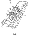
- FIG. 1 illustrates a system 100 for locating and restoring service lines during pipeline restoration, according to embodiments of the present invention.
- system 100 includes a movable cart 102 and an attachment part 104 associated with the movable cart 102. Attachment part 104 may be coupled with various mechanism and tools which will be later described.
- the system 100 also includes plug installer 106, coupled with attachment part 104, and plug 108.
- Coupled is used in its broadest sense to refer to elements which are connected, attached, and/or engaged, either directly or integrally or indirectly via other elements, and either permanently, temporarily, or removably.
- service line is used in its broadest sense to refer any type of pipe, hose, line, or other system for fluid or gas movement.
- the movable cart 102 is a three axis movable motor assembly positioned on a skid lift mechanism.
- the three axis motor assembly includes a drill with a bit holder and a drill motor.
- Various attachments may be secured by the bit holder.
- a chuck or a drill bit holder are exemplary embodiments of attachment part 104, according to which the attachment part may be moved and rotated in three axis of direction.
- the system 100 also includes a lighting means 112 and a camera 110 such that the movements and location of system 100 may be determined and controlled during use.
- FIG. 2 illustrates a close up view of attachment part 104 which is associated with the movable cart 102, according to embodiments of the present invention.
- attachment part 104 may be coupled with plug installer 106 as is shown in FIG. 2 .
- FIG. 3 is illustrates attachment part 104 coupled with plug installer 106 which is shown with a plug 108, according to embodiments of the present invention.
- the plug installer for example, has an attachment side coupled to the attachment part 104 and an upper side configured to retain a plug 108.
- the upper side of plug installer 106 has a raised circular lip which grips the interior edge of plug 108 such that plug 108 remains on the upper side of plug installer 106 until plug is transferred into a service line 702 (as shown and described with respect to FIGS. 11a - 11d , below).
- plug 108 is a tapered polyethylene plug such as Lawson Products part number 90805 or 90815.
- Plug 108 may be of various diameters, materials, and shapes such that it is configured to seal service lines of a pipeline at the location where the service lines meet the pipeline. Other embodiments of plug 108 are described below.
- FIG. 4 illustrates plug locator 402 of system 100, where plug locator 402 is coupled with attachment part 104, according to embodiments of the present invention.
- Plug locator 402 has a movable magnet 404 as shown in FIGS. 4 and 5 which may be used to mark the location of previously installed plugs 108. Other embodiments of plug locator 402 are described below.
- FIG. 6 illustrates system 100 deployed along the inside of pipeline 602, according to embodiments of the present invention.
- FIG. 7 illustrates pipeline 602 with service lines 702 branching off from pipeline 602.
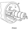
- FIG. 8 illustrates system 100 deployed along the inside of pipeline 602, according to embodiments of the present invention.
- plug remover 804 couples with attachment part 104.
- FIG. 8 also illustrates liner 802, according to embodiments of the present invention.
- a pipeline 602 may be rehabilitated by inserting a liner 802 therethrough, and cementing the liner 802 to an inside diameter of pipeline 604 with grout.
- Liner 802 may be, for example, a liner with grout hooks as described in U.S. Patent No. 6,167,913, issued on January 2, 2001 , and entitled "Pipe Liner, a Liner Product and Methods for Forming and Installing the Liner,".
- Liner 802 may be formed of an extruded medium-density polyethylene material or other polymer or polymer-like material; for example, liner 802 may be formed from a sheet of material created by Velcro® Europe S.A. According to some embodiments of the present invention, liner 802 conforms to ASTM - D1248: Type 11 , Class B, Category 5 standards, and based upon ISO classifications, may be classified as PE-80 or PE-100 material. According to some embodiments of the present invention, liner 802 is substantially resistant to ultraviolet radiation and is designed for potable water applications.
- liner 802 has a tensile strength at breakage of approximately 30 Mpa, an elongation at breakage of approximately 1,100%, a flexural modulus of approximately 700Mpa, a hardness of approximately 60 Shore D, a Vicat softening point of approximately 126° Celsius, a density at twenty-three degrees Celsius of approximately 942 kilograms per cubic meter, a weight of approximately 450 kilograms per square meter (plus or minus fifty grams per square meter), and a hook concentration of approximately twenty per square centimeter (plus or minus ten percent).
- a pipeline 602 may be rehabilitated by inserting a liner 802 therethrough, for example, by the method and system described in U.S. Patent Application No. 11/842,933 ( US 2008-0178955) filed on August 21 , 2007 , and entitled “Systems and Methods for Pipeline Rehabilitation Installation,”.
- a pipeline 602 may be rehabilitated by inserting a liner 802 therethrough, for example, by the method and system described in U.S. Patent Application No. 11/842,937 ( US 2009-0080980) filed on August 21, 2007 , and entitled "Systems and Methods for Installation Inspection in Pipeline Rehabilitation,".
- FIGS. 9a - 9c illustrates a plug 108 according to embodiments of the present invention.
- FIG. 9a shows an exploded view of an exemplary plug 108 which may have a shell 902, a first foam layer 904, a second foam layer 908, and a marking magnet 906.
- the shell 902 is hollow and a marking magnet 906 is placed inside the hollow shell.
- a first foam layer 904 may be placed in the shell 902, then marking magnet 906 may be placed on top of the first foam layer 904, and lastly a second foam layer 908 is placed on top of marking magnet 906.
- the marking magnet 906 may be sealed in plug 108 using a silicon adhesive, or other glue or adhesive.
- plug 108 may be formed using a Room Temperature Vulcanizer (RTV).
- the marking magnet may be, for example, a neodymium magnet such as CMS Magnetics part number NR005-40NM.
- system 100 may be used to restore service lines 702 during pipeline rehabilitation by installing one or more plugs 108 into the service lines 702 off of the pipeline 602 such that any gap between the service line and the interior space of pipeline 602 is sealed off.
- Plug 108 for example, may be installed into service lines by coupling plug 108 with plug installer 106 which is in turn coupled with the attachment part 104 of system 100.
- System 100 may then be deployed within a pipeline 602 to locate service line 702 entrance points into pipeline 602.
- Movable cart 102 may, for example, locate service lines 702 using lighting means 112 and camera 110.
- Other locating means may be used such as, for example, an optical, electrical, magnetic, and/or sonar locating means.
- Movable cart 102 may be moved within pipeline 602.
- Attachment part 104 may be moved and rotated in three axes of direction to place plug 108 into the opening of service line 702 such that the opening is sealed.
- the plug locator 402 and also the plug remover 804 may be similarly moved and rotated in three axes of direction within the pipeline 602 as described above using the movable cart 102 and the attachment point 104 of system 100.
- a plug 108 may be installed into a service line 702 using the plug installer 106 coupled to the attachment part 104 as shown in FIG. 10 .
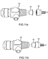
- a plug 108 may be installed into a service line 702 through the steps illustrated in FIGS. 11a - 11d in which pipeline 602 and attachment part 106 are omitted for simplification.
- plug 108 is coupled with plug installer 106 as illustrated in FIG. 11b .
- Plug is then coupled with the open end of service line 702 such that the opening of the service line to the pipeline 602 (not shown) is sealed as illustrated in FIG. 11c .
- Plug installer 106 is then moved radially away from open end of service line 702 disengaging plug installer 106 from plug 108 leaving plug 108 coupled with service line 702 as illustrated in FIG. 11d .
- the pipeline 602 may be rehabilitated using a liner 802.
- the location of plug 108 may be determined using plug locator 402.
- the plug locator 402 determines the location of a plug 108 by detecting the location of marking magnet 906 of plug 108 through the installed liner 802.
- the marking of the location of magnet 906 may be accomplished by, for example but not limited to: creating a dimple or indent in the liner 702 with plug locator 402; creating a visual marking with pen, pencil, or marker; or leaving a separate magnet at the location magnetically engaged with marking magnet 906.
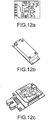
- the plug locator has an electromagnetic sensor as shown in FIGS. 12a - 12c which may be used to locate marking magnet 906 of plug 108.
- FIGS. 12a - 12c illustrate an electromagnetic sensor as shown in FIGS. 12a - 12c which may be used to locate marking magnet 906 of plug 108.
- FIG 12a illustrates a PNI Corporation's MicroMag3 integrated three-axis magnetic field sensing module
- FIG 12b illustrates a Honeywell HMC1052L magnetic sensor
- FIG 12c illustrates a Honeywell HMR2300 three-axis digital magnetometer.
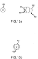
- the plug locator 402 may include a movable magnet 404 as is illustrated in FIGS. 4, 5 , 13a, and 13b .
- the plug locator 402 may have an attachment side 502 coupled with attachment part 104 and an upper side 504 configured to engage movable magnet 404.
- the upper side of plug locator 402 has a central raised bump 506 configured to engage a hole in the center of movable magnet 404.
- the movable magnet 404 and the plug locator 402 may be magnetically coupled, or may be nonmagnetically coupled.
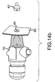
- FIG. 14a illustrates a plug locator 402, movable magnet 404, liner 802, and a plug 108 inserted inside the opening of service pipe 702, according to embodiments of the present invention.
- the location of a plug 108 may be determined by moving the movable magnet 404 which is coupled with plug locater 402 around the interior volume of pipe 702.
- the plug locater 402 may be moved while coupled to the attachment part 104 through movement of the movable cart 102.
- the movable magnet 404 will disengage from the plug locater 402 and magnetically engage with marking magnet 906 which is located within plug 108.
- the engagement of marking magnet 906 and plug locater 402 is illustrated in FIG. 14b .
- Multiple marking magnets 906 may be used to mark the location of multiple plugs 108.
- the one or more plugs 108 are removed from the service lines 702 using plug remover 804.
- the plug remover 804 may be moved to the location of plugs 108, for example, through the use of movable cart 102, camera 110 and lighting means 112 to determine the marked locations of plugs 108.
- plug remover 804 may be coupled with attachment part 104.
- Attachment part 104 may be, for example, a drill bit holder which permits the attachment part 104 to move and rotate in three axes of direction.
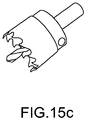
- An exemplary plug remover 804 may be a drill bit, such as, but not limited to: a circular drill bit, a circular drill bit with a centering device which may drill through a hole in movable magnet 404, and/or the drill bit illustrated in FIGS. 15a & 15b .
- FIG. 15c illustrates an embodiment of plug remover 804.
- plug remover 804 cuts through the liner 802 and the plug 108 such that an opening is created between the interior of the pipeline 602 and the interior of service lines 702. After the opening is created as is shown in FIG. 15b , the plug falls through the opening due to gravity, according to embodiments of the present invention.
- the plug is removed from the opening by having a plug remover magnet attached to plug remover 804 which magnetically couples to plug 108, specifically marking magnet 906, such that as the plug remover is pulled out of the opening, the plug 108 will also be magnetically coupled to plug remover 804 and be removed from the opening simultaneously with the plug remover 804.
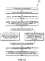
- FIG. 16 depicts a flow diagram 1600 illustrating a method for locating and restoring service lines in pipeline rehabilitation, according to embodiments of the present invention.
- a movable cart 102 may be deployed with a pipeline 602.
- One or more plugs 108 may be installed into service lines 702 branching from a pipeline 602.
- a tubular liner 802 may be installed within pipeline 602 by filling the space between the tubular liner 802 and the pipeline 602 with grout.
- the movable cart 102 may then be deployed with a plug locator 402.
- the location of plugs 108 may be marked using a plug locator 402 and a movable magnet 404.
- the location of the plugs may be marked using a plug locator 402 and an electronic sensor.
- the movable cart 102 may then be deployed with plug remover 804.
- the tubular liner 802 may then be cut at the marked locations
- the plugs 108 may be removed from the service lines 702 to restore a fluid connection between the pipeline 602 and service line 702, according to embodiments of the present invention.
Landscapes
- Engineering & Computer Science (AREA)
- General Engineering & Computer Science (AREA)
- Mechanical Engineering (AREA)
- Chemical & Material Sciences (AREA)
- Combustion & Propulsion (AREA)
- Pipe Accessories (AREA)
Claims (14)
- System (100) zum Auffinden und Restaurieren von Versorgungsleitungen bei Pipeline-Restaurierung, wobei das System (100) umfasst:einen beweglichen Wagen (102), der zur Verwendung entlang einer Innenseite einer Pipeline ausgelegt ist; undein Befestigungsteil (104), das mit dem beweglichen Wagen (102) gekoppelt ist;dadurch gekennzeichnet, dass:das System (100) ferner einen Stopfen (108) umfasst, der einen Markierungsmagnet (906) umfasst;ein Stopfenpositionierelement (402) zum Koppeln mit dem Befestigungsteil (104) angepasst ist, wobei das Stopfenpositionierelement (402) mit einem verschiebbaren Magnet (404) verbunden ist, und wobei das Befestigungsteil (104) ausgelegt ist, den Stopfen (108) in eine Versorgungsleitung an einer Stelle zu installieren, wo die Versorgungsleitung die Pipeline schneidet, wobei der verschiebbare Magnet (404) ausgelegt ist, sich vom Befestigungsteil (104), auf einem Magnetfeld des Markierungsmagneten (906) beruhend, zu trennen, um den Markierungsmagnet (906) und den Stopfen (108) zu positionieren, und wobei das Befestigungsteil (104) ausgelegt ist, den Stopfen (108) von der Versorgungsleitung zu entfernen und eine Flüssigkeitsverbindung zwischen der Versorgungsleitung und der Pipeline wieder herzustellen.
- System (100) nach Anspruch 1, wobei das Befestigungsteil (104) ausgelegt ist, die Position zu markieren.
- System (100) nach Anspruch 1, wobei das Befestigungsteil (104) ein Stopfeninstallierelement (106) umfasst, und wobei das Stopfeninstallierelement (106) angepasst ist, den Stopfen (108) an der Position in die Versorgungsleitung zu installieren.
- System (100) nach Anspruch 3, wobei das Stopfeninstallierelement (106) eine Befestigungsseite, die an das Befestigungsteil (104) gekoppelt ist und eine Oberseite umfasst, die ausgelegt ist, den Stopfen (108) festzuhalten, wobei die Oberseite eine erhabene Lippe aufweist, die ausgelegt ist, eine innere Kante des Stopfen (108) zu ergreifen, und wobei der Stopfen (108) auf der Oberseite des Stopfeninstallierelements (106) verbleibt, bis der Stopfen (108) in die Versorgungsleitung installiert ist.
- System (100) nach Anspruch 1, wobei das Stopfenpositionierelement (402) ausgelegt ist, eine Position des Stopfens (108) durch Abtasten des Markierungsmagneten (906) zu markieren.
- System (100) nach Anspruch 5, wobei das Stopfenpositionierelement (402) ein unteres Teil (502) und eine Positionierelementseite (504) umfasst, wobei das untere Teil (502) an das Befestigungsteil (104) gekoppelt ist, wobei die Positionierelementseite (504) mit dem verschiebbaren Magnet (404) verbunden ist, und wobei der verschiebbare Magnet (404) ausgelegt ist, die Position des Markierungsmagneten (906) und des Stopfens (108) zu markieren.
- System (100) nach Anspruch 6, wobei in der Mitte des verschiebbaren Magneten (404) ein Loch geformt ist, wobei die Positionierelementseite (504) des Stopfenpositionierelements (402) einen erhabenen Höcker (506) einschließt, und wobei der erhabene Höcker (506) ausgelegt ist, in das Loch einzurasten.
- System (100) nach Anspruch 1, das ferner ein Stopfenentfernelement er (804) umfasst, der ausgelegt ist, den Stopfen (108) aus der Versorgungsleitung zu entfernen und die Flüssigkeitsverbindung zwischen der Versorgungsleitung und der Pipeline wieder herzustellen.
- System (100) nach Anspruch 8, wobei das Stopfenentfernelement (804) den Markierungsmagnet (906) magnetisch detektiert und den Stopfen (108) einschließlich des Markierungsmagneten (906) aus der Versorgungsleitung entfernt.
- System (100) nach Anspruch 1, wobei der Stopfen (108):eine Hülle (902) und eine oder mehrere Schaumstoffschichten (904, 908) im Innern der Hülle (902) umfasst;Polyethylen umfasst und der Stopfen (108) eine verjüngte Konusform hat; und/oder eine hermetische Dichtung mit der Pipeline bildet, wenn der Stopfen (108) in der Versorgungsleitung installiert ist.
- System (100) nach Anspruch 1, wobei das Befestigungsteil (104) ausgelegt ist, sich in drei Drehachsen zu jeder Position innerhalb der Pipeline zu bewegen.
- Verfahren zum Auffinden und Restaurieren von Versorgungsleitungen (702) bei Pipeline-Restaurierung (602), wobei das Verfahren umfasst:Einfügen eines Stopfens (108) in eine Versorgungsleitungsöffnung, wobei der Stopfen (108) einen Markierungsmagnet (906) umfasst;Installieren eines rohrförmigen Liners (802) innerhalb der Pipeline (602);Bereitstellen eines Stopfenpositionierelements (402), der mit einem verschiebbaren Magnet (404) auf einem beweglichen Wagen (102) verbunden ist, wobei der Wagen (102) zur Verwendung entlang einer Innenseite der Pipeline (602) ausgelegt ist;Auffinden des Stopfens (108) durch Bewegen des Wagens (102) innerhalb der Pipeline (602), bis sich der bewegliche Magnet (404) des Stopfenpositionierelements (402) in Richtung des Markierungsmagneten (906) bewegt;Markieren einer Position des Stopfens (108); undEntfernen des Stopfens (108) aus der Versorgungsleitung, um eine Flüssigkeitsverbindung zwischen der Versorgungsleitung (702) und der Pipeline (602) wieder herzustellen.
- Verfahren nach Anspruch 12, wobei das Auffinden des Stopfens (108) ferner das Bewegen des Wagens (102) innerhalb der Pipeline (602) umfasst, bis der bewegliche Magnet (404) vom Wagen (102) an eine Innenseite des rohrförmigen Liners (802) in oder nahe der Position springt.
- Verfahren nach Anspruch 12, wobei das Auffinden des Stopfens (108) ferner das Abtasten eines Magnetfelds des Markierungsmagneten (906) umfasst.
Applications Claiming Priority (2)
| Application Number | Priority Date | Filing Date | Title |
|---|---|---|---|
| US2562708P | 2008-02-01 | 2008-02-01 | |
| PCT/US2009/032784 WO2009097598A1 (en) | 2008-02-01 | 2009-02-01 | Systems and methods for locating and restoring service lines in pipeline rehabilitation |
Publications (3)
| Publication Number | Publication Date |
|---|---|
| EP2245355A1 EP2245355A1 (de) | 2010-11-03 |
| EP2245355A4 EP2245355A4 (de) | 2014-05-21 |
| EP2245355B1 true EP2245355B1 (de) | 2018-07-18 |
Family
ID=40913296
Family Applications (1)
| Application Number | Title | Priority Date | Filing Date |
|---|---|---|---|
| EP09706594.0A Not-in-force EP2245355B1 (de) | 2008-02-01 | 2009-02-01 | Systeme und verfahren zur ortung und wiederherstellung von versorgungsleitungen bei der rohrleitungsrehabilitation |
Country Status (7)
| Country | Link |
|---|---|
| US (2) | US8567449B2 (de) |
| EP (1) | EP2245355B1 (de) |
| CN (2) | CN103899882B (de) |
| CA (1) | CA2762236C (de) |
| RU (1) | RU2555637C2 (de) |
| WO (1) | WO2009097598A1 (de) |
| ZA (1) | ZA201006194B (de) |
Cited By (1)
| Publication number | Priority date | Publication date | Assignee | Title |
|---|---|---|---|---|
| US12123537B2 (en) | 2021-02-11 | 2024-10-22 | Ina Acquisition Corp. | Mobile system for pipe rehabilitation |
Families Citing this family (16)
| Publication number | Priority date | Publication date | Assignee | Title |
|---|---|---|---|---|
| EP2245355B1 (de) * | 2008-02-01 | 2018-07-18 | Western Pipeway, LLC | Systeme und verfahren zur ortung und wiederherstellung von versorgungsleitungen bei der rohrleitungsrehabilitation |
| US8461473B2 (en) * | 2008-10-27 | 2013-06-11 | Wpw, Llc | External corrosion protection for underground pipes |
| US8561646B2 (en) * | 2009-12-23 | 2013-10-22 | Wpw, Llc | System and methods for multiple service line plug deployment |
| US8596917B2 (en) | 2010-05-13 | 2013-12-03 | Structural Group, Inc. | System for repairing and strengthening pipe with internal helically wound tensile reinforcement |
| WO2012024660A2 (en) * | 2010-08-20 | 2012-02-23 | Seektech, Inc. | Asymmetric drag force bearings for use with push-cable storage drums |
| US8864418B2 (en) | 2012-09-20 | 2014-10-21 | Sanexan Environmental Services Inc. | Method and apparatus for rehabilitating an underground water conduit and detecting and drilling a service entrance in the conduit |
| CN104896256B (zh) * | 2015-05-25 | 2017-03-08 | 广西建工集团第二安装建设有限公司 | 地下管道整形机 |
| DE102016120747A1 (de) * | 2016-10-31 | 2018-05-03 | Pipetronics Gmbh & Co. Kg | Verfahren und System zur messtechnischen Erfassung von Abzweigungen in einem zu sanierenden Leitungssystem |
| EP3385172B1 (de) * | 2017-04-05 | 2019-11-27 | thyssenkrupp Airport Solutions S.A. | Vorrichtung zur bereitstellung von klimatisierter luft in einem flugzeug |
| US11079055B2 (en) | 2018-10-30 | 2021-08-03 | Ina Acquisition Corp. | Fitting for connecting a main pipe liner to a branch conduit |
| US11774025B2 (en) | 2018-10-30 | 2023-10-03 | Ina Acquisition Corp. | Fitting for connecting a main pipe liner to a branch conduit |
| WO2020113125A1 (en) * | 2018-11-30 | 2020-06-04 | Ina Acqusition Corp. | Methods, systems, and apparatus for use in main pipes connected to branch conduits |
| CN111810759B (zh) * | 2020-07-07 | 2025-07-01 | 北京城市排水集团有限责任公司 | 一种排水管道封堵装置 |
| CA3134558A1 (en) | 2020-10-15 | 2022-04-15 | Ina Acquisition Corp. | Bit for removing a plug from a branch conduit |
| CN113236901A (zh) * | 2021-03-30 | 2021-08-10 | 四川吉石科技有限公司 | 一种水下管道缺陷修复方法 |
| CN114893649B (zh) * | 2022-07-14 | 2022-10-18 | 国机传感科技有限公司 | 一种管道内检测器卡堵定位装置及方法 |
Family Cites Families (32)
| Publication number | Priority date | Publication date | Assignee | Title |
|---|---|---|---|---|
| US3532132A (en) * | 1968-01-02 | 1970-10-06 | Chem Stress Ind Inc | Apparatus for the manufacture of reinforced composite concrete pipe-lines |
| US4893389A (en) * | 1986-03-25 | 1990-01-16 | Peter Allen | Reinstatement of lateral branch connections in relined sewers or pipes |
| US4982490A (en) | 1986-07-11 | 1991-01-08 | Stephen Tracey | Method of lining a fluid conduit |
| FR2622248B1 (fr) * | 1987-10-23 | 1990-02-02 | Elf Aquitaine | Procede et dispositif pour la mesure du deplacement d'une tige de pompage d'un puits pompe |
| GB8726073D0 (en) * | 1987-11-06 | 1987-12-09 | Rice N | Re-lining of sewers |
| US5333649A (en) * | 1989-01-06 | 1994-08-02 | Ashimori Kogyo Kabushiki Kaisha | Plug for blocking a branched pipe opening |
| US5074365A (en) * | 1990-09-14 | 1991-12-24 | Vector Magnetics, Inc. | Borehole guidance system having target wireline |
| CH685115A5 (de) | 1992-05-18 | 1995-03-31 | Sandherr Packungen Ag | Verpackungsbehälter. |
| US5485089A (en) * | 1992-11-06 | 1996-01-16 | Vector Magnetics, Inc. | Method and apparatus for measuring distance and direction by movable magnetic field source |
| JP2528429B2 (ja) * | 1993-08-31 | 1996-08-28 | 株式会社湘南合成樹脂製作所 | 枝管ライニング工法 |
| US5532598A (en) * | 1994-05-25 | 1996-07-02 | Westinghouse Electric Corporation | Amorphous metal tagging system for underground structures including elongated particles of amorphous metal embedded in nonmagnetic and nonconductive material |
| JP2605220B2 (ja) * | 1994-07-05 | 1997-04-30 | 株式会社湘南合成樹脂製作所 | 枝管ライニング工法 |
| US5577528A (en) * | 1994-11-18 | 1996-11-26 | Southern California Gas Company | Apparatus for upgrade or repair of in-service pipelines |
| US6024515A (en) * | 1996-03-04 | 2000-02-15 | Nicor Technologies Inc. | Live service pipe insertion apparatus and method |
| US6167912B1 (en) * | 1997-11-25 | 2001-01-02 | Patrick J. Stephens | Method and composition for grouting water-flooded conduits |
| JP2000052426A (ja) * | 1998-08-06 | 2000-02-22 | Shonan Gosei Jushi Seisakusho:Kk | 枝管ライニング材及び管ライニング工法 |
| JP3839597B2 (ja) * | 1998-10-26 | 2006-11-01 | 株式会社湘南合成樹脂製作所 | 管ライニング工法 |
| US6167913B1 (en) | 1999-01-13 | 2001-01-02 | Cempipe Ltd. | Pipe liner, a liner product and methods for forming and installing the liner |
| US20010029989A1 (en) * | 2000-02-17 | 2001-10-18 | Paz German N. | Pipeline identification and positioning system |
| CA2440344C (en) * | 2001-03-07 | 2007-06-26 | Carnegie Mellon University | Gas main robotic inspection system |
| US6807987B2 (en) * | 2001-09-12 | 2004-10-26 | Hill Steven D | Location marker |
| DE10204205A1 (de) * | 2002-02-02 | 2003-08-14 | Jt Elektronik Gmbh | Verfahren und Vorrichtung zur Sanierung von Abwasserkanälen |
| US7131791B2 (en) * | 2002-11-13 | 2006-11-07 | Redzone Robotics, Inc. | Pipeline rehabilitation systems |
| EP1519100B1 (de) * | 2003-09-25 | 2008-11-05 | Trelleborg epros GmbH | Vorrichtung und Verfahren zur Rohrsanierung |
| CN100447476C (zh) * | 2005-04-30 | 2008-12-31 | 中国科学院金属研究所 | 在役地下管道在线内涂层防护施工工艺 |
| US7878220B2 (en) * | 2005-08-17 | 2011-02-01 | Fierst Raymond V | Pipe plug with a locating appliance |
| RU2488735C2 (ru) * | 2006-08-21 | 2013-07-27 | Вестерн Пайпвей, Ллс | Системы и способ для восстановления трубопровода |
| US20080314468A1 (en) * | 2007-06-22 | 2008-12-25 | Jon Houghton | Cap or Plate With Electronic Or Magnetic Marker |
| EP2245355B1 (de) * | 2008-02-01 | 2018-07-18 | Western Pipeway, LLC | Systeme und verfahren zur ortung und wiederherstellung von versorgungsleitungen bei der rohrleitungsrehabilitation |
| US8561646B2 (en) * | 2009-12-23 | 2013-10-22 | Wpw, Llc | System and methods for multiple service line plug deployment |
| US8646520B2 (en) * | 2011-03-15 | 2014-02-11 | Baker Hughes Incorporated | Precision marking of subsurface locations |
| US20130156506A1 (en) * | 2011-12-20 | 2013-06-20 | Oliner System Llc | Method for Renewal or Rehabilitation of Water Supply Pipelines and Plug Arrangement for use in Said Method |
-
2009
- 2009-02-01 EP EP09706594.0A patent/EP2245355B1/de not_active Not-in-force
- 2009-02-01 US US12/363,782 patent/US8567449B2/en active Active
- 2009-02-01 CA CA2762236A patent/CA2762236C/en active Active
- 2009-02-01 CN CN201410003255.3A patent/CN103899882B/zh not_active Expired - Fee Related
- 2009-02-01 WO PCT/US2009/032784 patent/WO2009097598A1/en not_active Ceased
- 2009-02-01 RU RU2010136715/06A patent/RU2555637C2/ru not_active IP Right Cessation
- 2009-02-01 CN CN200980112337.9A patent/CN102007336B/zh not_active Expired - Fee Related
-
2010
- 2010-08-30 ZA ZA2010/06194A patent/ZA201006194B/en unknown
-
2013
- 2013-04-18 US US13/865,813 patent/US9494270B2/en not_active Expired - Fee Related
Non-Patent Citations (1)
| Title |
|---|
| None * |
Cited By (1)
| Publication number | Priority date | Publication date | Assignee | Title |
|---|---|---|---|---|
| US12123537B2 (en) | 2021-02-11 | 2024-10-22 | Ina Acquisition Corp. | Mobile system for pipe rehabilitation |
Also Published As
| Publication number | Publication date |
|---|---|
| CN103899882B (zh) | 2016-05-11 |
| RU2555637C2 (ru) | 2015-07-10 |
| RU2010136715A (ru) | 2012-03-10 |
| US9494270B2 (en) | 2016-11-15 |
| CN102007336B (zh) | 2014-02-19 |
| CN103899882A (zh) | 2014-07-02 |
| CN102007336A (zh) | 2011-04-06 |
| CA2762236C (en) | 2016-08-23 |
| CA2762236A1 (en) | 2009-08-06 |
| EP2245355A4 (de) | 2014-05-21 |
| WO2009097598A1 (en) | 2009-08-06 |
| US20130233428A1 (en) | 2013-09-12 |
| EP2245355A1 (de) | 2010-11-03 |
| US8567449B2 (en) | 2013-10-29 |
| ZA201006194B (en) | 2011-09-28 |
| US20090272452A1 (en) | 2009-11-05 |
Similar Documents
| Publication | Publication Date | Title |
|---|---|---|
| EP2245355B1 (de) | Systeme und verfahren zur ortung und wiederherstellung von versorgungsleitungen bei der rohrleitungsrehabilitation | |
| US6161563A (en) | Plumbing tool | |
| US8561646B2 (en) | System and methods for multiple service line plug deployment | |
| US7131791B2 (en) | Pipeline rehabilitation systems | |
| US6564823B1 (en) | Method and apparatus for testing plumbing installations | |
| EP1368591B1 (de) | Verfahren zum abdichten | |
| TW200817616A (en) | Reinstatement of an existing connection in a lined conduit | |
| AU2009202879A1 (en) | Remote tapping method and system for internally tapping a conduit | |
| US8636447B1 (en) | System and method for repairing and extended length of a subsea pipeline | |
| US5979508A (en) | Pipe protector | |
| EP3289175A1 (de) | Bohrlochrohranordnung einer bohrlochrohrstruktur | |
| EP3807492B1 (de) | Verfahren zur herstellung eines rohrförmigen bohrlochs mit einer elastomerhülse | |
| HK1150247B (en) | Systems and methods for locating and restoring service lines in pipeline rehabilitation | |
| HK1150247A (en) | Systems and methods for locating and restoring service lines in pipeline rehabilitation | |
| KR100770154B1 (ko) | 관로탐사선을 구비한 합성수지관 | |
| WO2009102554A1 (en) | Method and apparatus to measure features in a conduit | |
| JP2003293679A (ja) | 土壌汚染検知具 | |
| CN101506448A (zh) | 塞子组件 | |
| SE9800480D0 (sv) | Sätt att ansluta en rörledning till ett rör samt anordning för genomförande av sättet | |
| JP3022453B2 (ja) | 埋設管のバルブ開閉器具とその設置方法 | |
| AU715649C (en) | Testing of plumbing installations and plumbing tool | |
| MXPA06003964A (en) | Remote tapping method and system for internally tapping a conduit |
Legal Events
| Date | Code | Title | Description |
|---|---|---|---|
| PUAI | Public reference made under article 153(3) epc to a published international application that has entered the european phase |
Free format text: ORIGINAL CODE: 0009012 |
|
| 17P | Request for examination filed |
Effective date: 20100825 |
|
| AK | Designated contracting states |
Kind code of ref document: A1 Designated state(s): AT BE BG CH CY CZ DE DK EE ES FI FR GB GR HR HU IE IS IT LI LT LU LV MC MK MT NL NO PL PT RO SE SI SK TR |
|
| AX | Request for extension of the european patent |
Extension state: AL BA RS |
|
| RAP1 | Party data changed (applicant data changed or rights of an application transferred) |
Owner name: WESTERN PIPEWAY, LLC |
|
| DAX | Request for extension of the european patent (deleted) | ||
| REG | Reference to a national code |
Ref country code: HK Ref legal event code: DE Ref document number: 1150247 Country of ref document: HK |
|
| A4 | Supplementary search report drawn up and despatched |
Effective date: 20140422 |
|
| RIC1 | Information provided on ipc code assigned before grant |
Ipc: F16L 55/11 20060101AFI20140414BHEP Ipc: F16L 55/26 20060101ALI20140414BHEP |
|
| 17Q | First examination report despatched |
Effective date: 20151005 |
|
| STAA | Information on the status of an ep patent application or granted ep patent |
Free format text: STATUS: EXAMINATION IS IN PROGRESS |
|
| REG | Reference to a national code |
Ref country code: DE Ref legal event code: R079 Ref document number: 602009053304 Country of ref document: DE Free format text: PREVIOUS MAIN CLASS: F16L0055110000 Ipc: F16L0101700000 |
|
| GRAP | Despatch of communication of intention to grant a patent |
Free format text: ORIGINAL CODE: EPIDOSNIGR1 |
|
| STAA | Information on the status of an ep patent application or granted ep patent |
Free format text: STATUS: GRANT OF PATENT IS INTENDED |
|
| RIC1 | Information provided on ipc code assigned before grant |
Ipc: F16L 101/70 20060101AFI20180110BHEP Ipc: F16L 55/48 20060101ALI20180110BHEP Ipc: F16L 55/179 20060101ALI20180110BHEP Ipc: F16L 55/165 20060101ALI20180110BHEP Ipc: F16L 55/26 20060101ALI20180110BHEP |
|
| INTG | Intention to grant announced |
Effective date: 20180201 |
|
| GRAS | Grant fee paid |
Free format text: ORIGINAL CODE: EPIDOSNIGR3 |
|
| GRAA | (expected) grant |
Free format text: ORIGINAL CODE: 0009210 |
|
| STAA | Information on the status of an ep patent application or granted ep patent |
Free format text: STATUS: THE PATENT HAS BEEN GRANTED |
|
| AK | Designated contracting states |
Kind code of ref document: B1 Designated state(s): AT BE BG CH CY CZ DE DK EE ES FI FR GB GR HR HU IE IS IT LI LT LU LV MC MK MT NL NO PL PT RO SE SI SK TR |
|
| REG | Reference to a national code |
Ref country code: GB Ref legal event code: FG4D |
|
| REG | Reference to a national code |
Ref country code: CH Ref legal event code: EP |
|
| REG | Reference to a national code |
Ref country code: IE Ref legal event code: FG4D |
|
| REG | Reference to a national code |
Ref country code: DE Ref legal event code: R096 Ref document number: 602009053304 Country of ref document: DE |
|
| REG | Reference to a national code |
Ref country code: AT Ref legal event code: REF Ref document number: 1019744 Country of ref document: AT Kind code of ref document: T Effective date: 20180815 |
|
| REG | Reference to a national code |
Ref country code: NL Ref legal event code: MP Effective date: 20180718 |
|
| REG | Reference to a national code |
Ref country code: LT Ref legal event code: MG4D |
|
| REG | Reference to a national code |
Ref country code: AT Ref legal event code: MK05 Ref document number: 1019744 Country of ref document: AT Kind code of ref document: T Effective date: 20180718 |
|
| PG25 | Lapsed in a contracting state [announced via postgrant information from national office to epo] |
Ref country code: NL Free format text: LAPSE BECAUSE OF FAILURE TO SUBMIT A TRANSLATION OF THE DESCRIPTION OR TO PAY THE FEE WITHIN THE PRESCRIBED TIME-LIMIT Effective date: 20180718 |
|
| PG25 | Lapsed in a contracting state [announced via postgrant information from national office to epo] |
Ref country code: GR Free format text: LAPSE BECAUSE OF FAILURE TO SUBMIT A TRANSLATION OF THE DESCRIPTION OR TO PAY THE FEE WITHIN THE PRESCRIBED TIME-LIMIT Effective date: 20181019 Ref country code: BG Free format text: LAPSE BECAUSE OF FAILURE TO SUBMIT A TRANSLATION OF THE DESCRIPTION OR TO PAY THE FEE WITHIN THE PRESCRIBED TIME-LIMIT Effective date: 20181018 Ref country code: IS Free format text: LAPSE BECAUSE OF FAILURE TO SUBMIT A TRANSLATION OF THE DESCRIPTION OR TO PAY THE FEE WITHIN THE PRESCRIBED TIME-LIMIT Effective date: 20181118 Ref country code: NO Free format text: LAPSE BECAUSE OF FAILURE TO SUBMIT A TRANSLATION OF THE DESCRIPTION OR TO PAY THE FEE WITHIN THE PRESCRIBED TIME-LIMIT Effective date: 20181018 Ref country code: AT Free format text: LAPSE BECAUSE OF FAILURE TO SUBMIT A TRANSLATION OF THE DESCRIPTION OR TO PAY THE FEE WITHIN THE PRESCRIBED TIME-LIMIT Effective date: 20180718 Ref country code: LT Free format text: LAPSE BECAUSE OF FAILURE TO SUBMIT A TRANSLATION OF THE DESCRIPTION OR TO PAY THE FEE WITHIN THE PRESCRIBED TIME-LIMIT Effective date: 20180718 Ref country code: FI Free format text: LAPSE BECAUSE OF FAILURE TO SUBMIT A TRANSLATION OF THE DESCRIPTION OR TO PAY THE FEE WITHIN THE PRESCRIBED TIME-LIMIT Effective date: 20180718 Ref country code: SE Free format text: LAPSE BECAUSE OF FAILURE TO SUBMIT A TRANSLATION OF THE DESCRIPTION OR TO PAY THE FEE WITHIN THE PRESCRIBED TIME-LIMIT Effective date: 20180718 Ref country code: PL Free format text: LAPSE BECAUSE OF FAILURE TO SUBMIT A TRANSLATION OF THE DESCRIPTION OR TO PAY THE FEE WITHIN THE PRESCRIBED TIME-LIMIT Effective date: 20180718 |
|
| PG25 | Lapsed in a contracting state [announced via postgrant information from national office to epo] |
Ref country code: LV Free format text: LAPSE BECAUSE OF FAILURE TO SUBMIT A TRANSLATION OF THE DESCRIPTION OR TO PAY THE FEE WITHIN THE PRESCRIBED TIME-LIMIT Effective date: 20180718 Ref country code: HR Free format text: LAPSE BECAUSE OF FAILURE TO SUBMIT A TRANSLATION OF THE DESCRIPTION OR TO PAY THE FEE WITHIN THE PRESCRIBED TIME-LIMIT Effective date: 20180718 Ref country code: ES Free format text: LAPSE BECAUSE OF FAILURE TO SUBMIT A TRANSLATION OF THE DESCRIPTION OR TO PAY THE FEE WITHIN THE PRESCRIBED TIME-LIMIT Effective date: 20180718 |
|
| REG | Reference to a national code |
Ref country code: DE Ref legal event code: R097 Ref document number: 602009053304 Country of ref document: DE |
|
| PG25 | Lapsed in a contracting state [announced via postgrant information from national office to epo] |
Ref country code: EE Free format text: LAPSE BECAUSE OF FAILURE TO SUBMIT A TRANSLATION OF THE DESCRIPTION OR TO PAY THE FEE WITHIN THE PRESCRIBED TIME-LIMIT Effective date: 20180718 Ref country code: CZ Free format text: LAPSE BECAUSE OF FAILURE TO SUBMIT A TRANSLATION OF THE DESCRIPTION OR TO PAY THE FEE WITHIN THE PRESCRIBED TIME-LIMIT Effective date: 20180718 Ref country code: RO Free format text: LAPSE BECAUSE OF FAILURE TO SUBMIT A TRANSLATION OF THE DESCRIPTION OR TO PAY THE FEE WITHIN THE PRESCRIBED TIME-LIMIT Effective date: 20180718 Ref country code: IT Free format text: LAPSE BECAUSE OF FAILURE TO SUBMIT A TRANSLATION OF THE DESCRIPTION OR TO PAY THE FEE WITHIN THE PRESCRIBED TIME-LIMIT Effective date: 20180718 |
|
| PLBE | No opposition filed within time limit |
Free format text: ORIGINAL CODE: 0009261 |
|
| STAA | Information on the status of an ep patent application or granted ep patent |
Free format text: STATUS: NO OPPOSITION FILED WITHIN TIME LIMIT |
|
| PG25 | Lapsed in a contracting state [announced via postgrant information from national office to epo] |
Ref country code: SK Free format text: LAPSE BECAUSE OF FAILURE TO SUBMIT A TRANSLATION OF THE DESCRIPTION OR TO PAY THE FEE WITHIN THE PRESCRIBED TIME-LIMIT Effective date: 20180718 Ref country code: DK Free format text: LAPSE BECAUSE OF FAILURE TO SUBMIT A TRANSLATION OF THE DESCRIPTION OR TO PAY THE FEE WITHIN THE PRESCRIBED TIME-LIMIT Effective date: 20180718 |
|
| 26N | No opposition filed |
Effective date: 20190423 |
|
| REG | Reference to a national code |
Ref country code: DE Ref legal event code: R082 Ref document number: 602009053304 Country of ref document: DE Representative=s name: HERZOG IP PATENTANWALTS GMBH, DE |
|
| PG25 | Lapsed in a contracting state [announced via postgrant information from national office to epo] |
Ref country code: SI Free format text: LAPSE BECAUSE OF FAILURE TO SUBMIT A TRANSLATION OF THE DESCRIPTION OR TO PAY THE FEE WITHIN THE PRESCRIBED TIME-LIMIT Effective date: 20180718 |
|
| REG | Reference to a national code |
Ref country code: CH Ref legal event code: PL |
|
| PG25 | Lapsed in a contracting state [announced via postgrant information from national office to epo] |
Ref country code: MC Free format text: LAPSE BECAUSE OF FAILURE TO SUBMIT A TRANSLATION OF THE DESCRIPTION OR TO PAY THE FEE WITHIN THE PRESCRIBED TIME-LIMIT Effective date: 20180718 Ref country code: LU Free format text: LAPSE BECAUSE OF NON-PAYMENT OF DUE FEES Effective date: 20190201 |
|
| REG | Reference to a national code |
Ref country code: BE Ref legal event code: MM Effective date: 20190228 |
|
| REG | Reference to a national code |
Ref country code: IE Ref legal event code: MM4A |
|
| PG25 | Lapsed in a contracting state [announced via postgrant information from national office to epo] |
Ref country code: LI Free format text: LAPSE BECAUSE OF NON-PAYMENT OF DUE FEES Effective date: 20190228 Ref country code: CH Free format text: LAPSE BECAUSE OF NON-PAYMENT OF DUE FEES Effective date: 20190228 |
|
| PG25 | Lapsed in a contracting state [announced via postgrant information from national office to epo] |
Ref country code: IE Free format text: LAPSE BECAUSE OF NON-PAYMENT OF DUE FEES Effective date: 20190201 |
|
| PG25 | Lapsed in a contracting state [announced via postgrant information from national office to epo] |
Ref country code: BE Free format text: LAPSE BECAUSE OF NON-PAYMENT OF DUE FEES Effective date: 20190228 |
|
| PG25 | Lapsed in a contracting state [announced via postgrant information from national office to epo] |
Ref country code: TR Free format text: LAPSE BECAUSE OF FAILURE TO SUBMIT A TRANSLATION OF THE DESCRIPTION OR TO PAY THE FEE WITHIN THE PRESCRIBED TIME-LIMIT Effective date: 20180718 |
|
| PG25 | Lapsed in a contracting state [announced via postgrant information from national office to epo] |
Ref country code: MT Free format text: LAPSE BECAUSE OF NON-PAYMENT OF DUE FEES Effective date: 20190201 Ref country code: PT Free format text: LAPSE BECAUSE OF FAILURE TO SUBMIT A TRANSLATION OF THE DESCRIPTION OR TO PAY THE FEE WITHIN THE PRESCRIBED TIME-LIMIT Effective date: 20181118 |
|
| PG25 | Lapsed in a contracting state [announced via postgrant information from national office to epo] |
Ref country code: CY Free format text: LAPSE BECAUSE OF FAILURE TO SUBMIT A TRANSLATION OF THE DESCRIPTION OR TO PAY THE FEE WITHIN THE PRESCRIBED TIME-LIMIT Effective date: 20180718 |
|
| PG25 | Lapsed in a contracting state [announced via postgrant information from national office to epo] |
Ref country code: HU Free format text: LAPSE BECAUSE OF FAILURE TO SUBMIT A TRANSLATION OF THE DESCRIPTION OR TO PAY THE FEE WITHIN THE PRESCRIBED TIME-LIMIT; INVALID AB INITIO Effective date: 20090201 |
|
| PGFP | Annual fee paid to national office [announced via postgrant information from national office to epo] |
Ref country code: GB Payment date: 20220225 Year of fee payment: 14 Ref country code: DE Payment date: 20220225 Year of fee payment: 14 |
|
| PGFP | Annual fee paid to national office [announced via postgrant information from national office to epo] |
Ref country code: FR Payment date: 20220223 Year of fee payment: 14 |
|
| PG25 | Lapsed in a contracting state [announced via postgrant information from national office to epo] |
Ref country code: MK Free format text: LAPSE BECAUSE OF FAILURE TO SUBMIT A TRANSLATION OF THE DESCRIPTION OR TO PAY THE FEE WITHIN THE PRESCRIBED TIME-LIMIT Effective date: 20180718 |
|
| REG | Reference to a national code |
Ref country code: DE Ref legal event code: R119 Ref document number: 602009053304 Country of ref document: DE |
|
| GBPC | Gb: european patent ceased through non-payment of renewal fee |
Effective date: 20230201 |
|
| PG25 | Lapsed in a contracting state [announced via postgrant information from national office to epo] |
Ref country code: GB Free format text: LAPSE BECAUSE OF NON-PAYMENT OF DUE FEES Effective date: 20230201 |
|
| PG25 | Lapsed in a contracting state [announced via postgrant information from national office to epo] |
Ref country code: GB Free format text: LAPSE BECAUSE OF NON-PAYMENT OF DUE FEES Effective date: 20230201 Ref country code: FR Free format text: LAPSE BECAUSE OF NON-PAYMENT OF DUE FEES Effective date: 20230228 Ref country code: DE Free format text: LAPSE BECAUSE OF NON-PAYMENT OF DUE FEES Effective date: 20230901 |