EP2244927B1 - Colonne de direction comportant une douille de coulissage en plastique - Google Patents
Colonne de direction comportant une douille de coulissage en plastique Download PDFInfo
- Publication number
- EP2244927B1 EP2244927B1 EP09701644A EP09701644A EP2244927B1 EP 2244927 B1 EP2244927 B1 EP 2244927B1 EP 09701644 A EP09701644 A EP 09701644A EP 09701644 A EP09701644 A EP 09701644A EP 2244927 B1 EP2244927 B1 EP 2244927B1
- Authority
- EP
- European Patent Office
- Prior art keywords
- jacket tube
- jacket
- plastic sleeve
- steering column
- tube
- Prior art date
- Legal status (The legal status is an assumption and is not a legal conclusion. Google has not performed a legal analysis and makes no representation as to the accuracy of the status listed.)
- Active
Links
- 239000004033 plastic Substances 0.000 title claims abstract description 98
- 229920001169 thermoplastic Polymers 0.000 claims abstract 3
- 239000004416 thermosoftening plastic Substances 0.000 claims abstract 3
- 238000006073 displacement reaction Methods 0.000 claims description 12
- 238000004519 manufacturing process Methods 0.000 claims description 9
- 238000000034 method Methods 0.000 claims description 9
- 238000002604 ultrasonography Methods 0.000 claims description 4
- 230000002093 peripheral effect Effects 0.000 claims description 3
- 239000000463 material Substances 0.000 description 5
- 230000005489 elastic deformation Effects 0.000 description 3
- 230000015572 biosynthetic process Effects 0.000 description 2
- 238000001816 cooling Methods 0.000 description 2
- 238000010438 heat treatment Methods 0.000 description 2
- 238000003825 pressing Methods 0.000 description 2
- 229920005992 thermoplastic resin Polymers 0.000 description 2
- 230000004913 activation Effects 0.000 description 1
- 230000006835 compression Effects 0.000 description 1
- 238000007906 compression Methods 0.000 description 1
- 238000013016 damping Methods 0.000 description 1
- 238000011161 development Methods 0.000 description 1
- 230000018109 developmental process Effects 0.000 description 1
- 230000005284 excitation Effects 0.000 description 1
- 238000009434 installation Methods 0.000 description 1
- 239000002991 molded plastic Substances 0.000 description 1
- 238000000465 moulding Methods 0.000 description 1
- 230000005855 radiation Effects 0.000 description 1
- 239000007787 solid Substances 0.000 description 1
- 238000003860 storage Methods 0.000 description 1
- 239000012815 thermoplastic material Substances 0.000 description 1
Images


Classifications
-
- B—PERFORMING OPERATIONS; TRANSPORTING
- B62—LAND VEHICLES FOR TRAVELLING OTHERWISE THAN ON RAILS
- B62D—MOTOR VEHICLES; TRAILERS
- B62D1/00—Steering controls, i.e. means for initiating a change of direction of the vehicle
- B62D1/02—Steering controls, i.e. means for initiating a change of direction of the vehicle vehicle-mounted
- B62D1/16—Steering columns
- B62D1/18—Steering columns yieldable or adjustable, e.g. tiltable
- B62D1/185—Steering columns yieldable or adjustable, e.g. tiltable adjustable by axial displacement, e.g. telescopically
-
- Y—GENERAL TAGGING OF NEW TECHNOLOGICAL DEVELOPMENTS; GENERAL TAGGING OF CROSS-SECTIONAL TECHNOLOGIES SPANNING OVER SEVERAL SECTIONS OF THE IPC; TECHNICAL SUBJECTS COVERED BY FORMER USPC CROSS-REFERENCE ART COLLECTIONS [XRACs] AND DIGESTS
- Y10—TECHNICAL SUBJECTS COVERED BY FORMER USPC
- Y10T—TECHNICAL SUBJECTS COVERED BY FORMER US CLASSIFICATION
- Y10T29/00—Metal working
- Y10T29/49—Method of mechanical manufacture
- Y10T29/49826—Assembling or joining
- Y10T29/49908—Joining by deforming
Definitions
- the present invention relates to a steering column assembly having the features of the preamble of claim 1 and a manufacturing method having the features of the preamble of claim 9.
- Steering columns in motor vehicles are generally adjustable to adjust the position of the steering wheel to the needs of different drivers.
- For the axial adjustability of the steering column an arrangement of two concentric tubes is often provided in the prior art, which are telescopically movable in one another. Between the two tubes, a bearing is provided, which ensures the axial displaceability and possibly also allows a relative rotation.
- a similar structure also have not axially adjustable steering columns, in which two coaxial shell parts are slidably mounted one inside the other to allow compression of the steering column in an impact.
- Plastic elements combine self-lubricating properties with vibration-damping properties and are therefore particularly suitable for this camp.
- EP 1717127A1 shows a telescopic guide for a steering column with a plastic bushing, which is inserted between a shaft and a surrounding jacket tube. This bush is attached to the inner shaft with molded plastic elements and slides in the axial direction and in the circumferential direction in the surrounding casing pipe.
- EP 1754646A2 a bearing sleeve for a telescopic steering column. This sleeve is elaborately designed and provided with special support elements, which should provide for a low-backlash support of the two inter-rotatable and displaceable pipe parts. This storage is particularly complex.
- US 2005 / 0200111A1 discloses a steering column assembly according to the preamble of claim 1.
- a steering column for a motor vehicle with a bracket which carries an upper shell unit and a lower shell unit, wherein the shell units surround a rotatably mounted therein steering shaft and wherein the shell units an inner jacket tube, with an outer surface and the inner Casing tube at least partially surrounding outer casing tube, which in its axial direction into one another by means of an intervening thermoplastic resin sleeve which has an inner surface, which is directed to the inner casing tube, and an outer surface, which is directed to the outer casing tube, slidably mounted, according to the invention the plastic sleeve is inserted with a press fit into the outer jacket tube and in which the outer jacket tube has at least one opening, in the region of the plastic sleeve on its inner surface projections in the direction of the inner jacket tube, respectively a central axis, on which the plastic sleeve is applied to the outer surface of the inner casing tube.
- the plastic sleeve acts as a sliding sleeve.
- the plant of the projections is either by a plastic or by an elastic or by a combination of plastic and elastic deformation causes.
- the elastic deformation is effected in the preferred case by a spring element which acts resiliently on the projections in the direction of the surface of the inner jacket tube.
- the object is achieved with a method for producing a telescopic steering column for a motor vehicle, with a console which carries an upper shell unit and a lower shell unit, wherein the shell units rotatably mounted therein a steering shaft and wherein the shell units an inner jacket tube, with a outer surface, and an inner jacket tube at least partially surrounding outer jacket tube, which are mounted displaceably in their axial direction by means of an interposed thermoplastic resin sleeve, according to the invention, the plastic sleeve is inserted with a press fit into the outer jacket tube, the inner jacket tube with a sliding seat is introduced into the plastic sleeve and that in the region of at least one breakthrough of the outer jacket tube, the plastic sleeve is applied by plastic deformation of the inner jacket tube.
- the plastic deformation is achieved in the preferred case by a deformation, in the simplest case pressing, under the action of heat.
- the heating is carried out by ultrasound, which is effected with a sonotrode, which is also used as a press die.
- an elastic deformation can be effected by a prestressed spring element.
- the plastic sleeve is inserted with a press fit into the outer jacket tube and the outer jacket tube has at least one breakthrough, in the region of the plastic sleeve is created by deformation of the inner jacket tube, a virtually backlash-free connection is ensured that does not affect the telescoping. The driver is thus taught a safe and firm feeling when operating the steering column.
- the openings are provided with respect to the axial direction of the jacket tubes in at least two axially spaced positions, and leverage forces can be absorbed, which act on the steering column, so that tilting of the jacket tubes is prevented each other, for example, in an impact.
- An important advantage of the invention is the possibility Use inexpensive and simply shaped sonotrodes for production.
- the sonotrode should only be able to pass through the openings.
- openings are formed as slots which extend at least partially in the circumferential direction of the outer jacket tube, line-shaped or rectangular-shaped installations can be achieved.
- Plastic sleeve is applied by plastic deformation of the inner casing tube, only a few components, which also identify a particularly simple design, required. Backlash is achieved in particular by the fact that the plastic deformation of the plastic sleeve takes place by the action of heat. It may be advantageous if the plastic deformation takes place by the action of ultrasound and radial pressure.
- a safe function in an impact, but also when used as an axially adjustable steering column is promoted when the inner casing tube has such a smooth outer surface, that even after investment of the plastic sleeve due to the local deformation a displacement of the inner casing tube is made possible in the plastic sleeve.
- a recess can also on the inner Jacket tube a recess, be provided corresponding to a recess on the outer jacket tube into which - also with a sonotrode - is pressed from the outside material of the plastic sleeve.
- a breakaway element can be formed, which releases only when a certain force is exceeded in the direction of displacement of the two jacket tubes, the displacement.
- the breakaway element can also be arranged directly at the end or even with a certain distance to the end of the inner Matelrohres, wordurch can be dispensed with a special recess on the inner casing tube.
- a particular advantage of the solution according to the invention is that the projections, which are arranged to form the contact areas between the plastic sleeve and the inner jacket tube and / or the formation of breakaway elements on the plastic sleeve, in one piece, and not as separate parts, which are then joined must, are formed with the plastic sleeve.
- the use of the solution according to the invention can be carried out in steering columns, which are in their height and / or in their length or not at all adjustable.
- the plastic sleeve serves as a guide element in the event of a crash.
- the plastic sleeve can also serve for guidance during the adjustment.
- a breakaway element may be provided which limits the displacement during an adjustment by the driver.
- the Fig. 1 shows in perspective a steering column for a motor vehicle with a bracket 1 to the body-mounted attachment.
- the console 1 carries a clamping system 2 for holding an upper shell unit 3 and a pivot bearing 4, in which a lower shell unit 5 is mounted.
- the upper shell unit 3 and the lower shell unit 5 are arranged concentrically with each other with the common central axis 26, which coincides with the axis of the steering shaft 8. They are essentially tubular.
- a plastic sleeve 6 is inserted between the upper shell unit 3 and the lower shell unit 5.
- the plastic sleeve 6 (see. Fig. 2 ) has an outer surface 25 and an inner surface 24 which are approximately parallel to each other.
- An adjusting lever 7 serves for actuating the clamping system 2.
- a steering shaft 8 is rotatably mounted in the interior of the jacket units 3 and 5, in which a steering shaft 8 is rotatably mounted.
- the invention is not limited to the embodiment in which the upper and lower shell units are arranged concentrically with each other. It is conceivable and possible to arrange the jacket units eccentrically to each other.
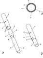
- the Fig. 2 shows the coaxially arranged components of the upper shell unit 3 and the lower shell unit 5 and the plastic sleeve 6 in a schematic representation prior to assembly.
- the lower jacket unit 1 in this case has an inner jacket tube 10 with an outer surface 27.
- the upper jacket unit 3 has an outer jacket tube 11.
- the plastic sleeve 6 is provided between the inner jacket tube 10 and the outer jacket tube 11, the plastic sleeve 6 is provided.
- a total of 4 apertures 12 are formed on the outer casing tube 11 on its outer peripheral surface, which are formed circular preference with preference.
- a further fitting bore 13 is arranged between the apertures 12.
- the plastic sleeve 6 carries a corresponding fitting bore 14, which is arranged centrally on the outer circumference.
- the Figure 3 shows the components of the Fig. 2 in assembled condition.
- the plastic sleeve 6 was pressed with a press fit into the outer jacket tube 11, with the advantage so far that the fitting bore 13 of the outer jacket tube 11 was brought to the fitting bore 14 of the plastic sleeve 6 to cover.
- the inner jacket tube 11 was then inserted with a sliding seat.
- the inner jacket tube 10 is axially displaceable with little effort in the plastic sleeve 6.
- the inner jacket tube 10 and the outer jacket tube 11 are arranged concentrically with each other with respect to the central axis 26.
- two jacket tubes 10, 11 eccentric to each other to order.
- the outer surface 25 of the plastic sleeve 6 is arranged eccentrically to the inner surface 24 of the plastic sleeve 6.
- the small eccentric offset between the inner casing 10 and the outer casing 11, which results from the formation of the projections 23 is neglected.
- fitting hole 14 can also be dispensed with.
- other means for positioning during assembly such as stops in the assembly tools, be provided or the plastic sleeve 6 is simply pressed into abutment in the outer casing tube 11.
- FIG. 4 Another manufacturing step is in the FIG. 4 also schematically illustrated.
- a sonotrode 15 is inserted into an opening 12 and brought into mechanical contact with the plastic sleeve 6 in the region of the opening 12.
- the plastic sleeve 6 Upon activation of the sonotrode 15, the plastic sleeve 6 is locally heated by the mechanical power of the introduced ultrasound and thereby softened.
- the plastic sleeve 6 is thereby deformed and pressed under mechanical pressure of the sonotrode 15 on the inner casing 10.
- This impression of the plastic sleeve 6 reduces the play of the inner jacket tube 10 in the plastic sleeve 6 to a small degree, preferably to zero. Accordingly, 12 moves in the other recesses, so that over the peripheral surface of the inner casing tube 10 result in several possible play-free investment points.
- the embodiment according to the FIG. 4 is in terms of in FIGS. 2 and 3 illustrated embodiment modified in such a way that in addition Breakaway elements 16, 18, 20 are provided.
- the breakaway elements are analogous to the investment points directly from the plastic sleeve 6 by means of a sonotrode, which is guided through the recesses 17, 19, 21 and heated by ultrasonic excitation of the plastic and causes a projection by pressing, so that the breakaway elements 16, 18, 20 in protrude the path of movement of the inner jacket tube 10.
- a breakaway element 16 is formed in a recess 22 in the inner jacket tube 10. Even if three breakaway elements are shown in the embodiment, the number is arbitrary. In particular, a single breakaway element can be sufficient.
- the length of the plastic sleeve is adapted to the requirements.
- the projections of the breakaway elements 16, 18, 20 project beyond the outer surface 27 of the inner jacket tube 10, preferably in a range of 0.5 mm to 4 mm, particularly preferably in the range of 1 mm to 2.5 mm. In this way it is achieved that a displacement of the two jacket tubes 10, 11 is prevented at least up to a predetermined force. At the same time, the breakaway element can be moved away or pushed back when a predeterminable force is exceeded, so that the displacement of the two jacket tubes 10, 11 relative to one another is made possible.
- a force here is the force in the direction of the central axis 26 on the jacket tubes 10, 11 for generating a shift, as occurs in particular in the event of a crash to understand.
- the breakaway element 20 is arranged such that only after reaching a certain displacement, the further displacement is prevented when falling below a corresponding force.
- the breakaway element 20 has a corresponding distance from the inner jacket tube 10 when the jacket units 3, 5 to the greatest length are pulled out.
- the recess 22 may be formed as a slot.
- FIG. 5 shows the state generated in the last-described process step in a cross-section, in which the three components are shown concentrically nested in one another.
- FIG. 6 Another embodiment is in FIG. 6 illustrated schematically.
- the plastic sleeve 6 is acted upon locally by its outer surface 25 with a spring force.
- a spring 28 is arranged, which passes through openings 12 in the outer jacket tube 11 and is held under tension with a fastening element 29 on the outer jacket tube 11.
- the plastic sleeve 6 is applied in predefined surface areas 30, corresponding to the projections 23, to the outer surface 27 of the inner casing tube 10, or elastically deformed and pressed accordingly.
- corresponding protrusions 23 have previously been formed in the plastic sleeve 6 by means of plastic deformation.
- Alternative embodiments of the invention may not have round jacket tubes and a correspondingly non-round plastic sleeve.
- the invention is also applicable to casing pipes 10, 11, in which the surfaces have one or more corresponding small flats to represent an anti-rotation. But there are also other polygonal or elliptical or other non-circular shapes conceivable and possible.
- the shape and arrangement of the apertures in the outer jacket tube may differ.
- breakthroughs may also be provided, which run slot-like in the circumferential direction of the outer jacket tube and thereby cover a circumferential angle of 45 ° to 180 °.
- the plastic sleeve is made of a thermoplastic material, so that not only the currently preferred plasticization of the material with an ultrasonic sonotrode is possible, but also other local heating can be used, for example by hot stamping or IR laser radiation. In the molding of slot-like openings is then too a linear contact surface of the inner jacket tube 10 on the plastic sleeve 6 can be achieved. It is also possible to achieve a deformation of the plastic sleeve 6 without mechanical pressure by using a plastic sleeve 6 which contracts when heated.
- the plastic sleeve 6 is heated in the region of the apertures of the outer jacket tube and then retracts alone due to their material properties such as the resulting surface tension inward towards the inner jacket tube 10 and thus comes in a safe and after cooling of the material also solid , play-free facility.
Landscapes
- Engineering & Computer Science (AREA)
- Chemical & Material Sciences (AREA)
- Combustion & Propulsion (AREA)
- Transportation (AREA)
- Mechanical Engineering (AREA)
- Steering Controls (AREA)
- Springs (AREA)
- Switches With Compound Operations (AREA)
- Sliding-Contact Bearings (AREA)
Claims (14)
- Colonne de direction pour un véhicule automobile, comprenant une console (1) qui porte une unité de fourreau supérieure (3) et une unité de fourreau inférieure (5), les unités de fourreau (3, 5) entourant un arbre de direction (8) qui y est monté rotatif, et les unités de fourreau (3, 5) comportant un tube de fourreau intérieur (10) avec une surface extérieure (27), ainsi qu'un tube de fourreau extérieur (11) entourant au moins par tronçons le tube de fourreau intérieur (10), ces tubes de fourreau étant montés coulissants l'un dans l'autre dans leur direction axiale au moyen d'une douille de matériau synthétique (6) thermoplastique placée entre eux, qui présente une surface intérieure (24) dirigée vers le tube de fourreau intérieur (10), et une surface extérieure (25) dirigée vers le tube de fourreau extérieur (11),
caractérisée en ce que la douille de matériau synthétique (6) est insérée par un ajustement à force dans le tube de fourreau extérieur (11), et en ce que le tube de fourreau extérieur (11) présente au moins une ouverture de passage (12) dans la zone de laquelle la douille de matériau synthétique (6) présente sur sa surface intérieure, des protubérances (23) dirigées vers le tube de fourreau intérieur (10) et par lesquelles la douille de matériau synthétique (6) s'applique contre la surface extérieure (27) du tube de fourreau intérieur (10) . - Colonne de direction selon la revendication 1, caractérisée en ce que dans le tube de fourreau extérieur est formé au moins un évidement (17, 19, 21) dans la, zone duquel la douille de matériau synthétique (6) présente, sur sa surface intérieure, une autre protubérance dont la distance à un axe central (26) des tubes de fourreau (10, 11) est inférieure à la distance à cet axe de la surface extérieure (27) du tube de fourreau intérieur (10), dans la zone de ladite protubérance.
- Colonne de direction selon la revendication 2, caractérisée en ce que ladite autre protubérance est réalisée en tant qu'élément de rupture (16, 18, 21), c'est-à-dire qu'il est sectionné dans le cas du dépassement d'une force déterminée agissant sur les deux tubes de fourreau (10, 11) dans la direction de coulissement de ces deux tubes de fourreau (10, 11), en autorisant ainsi le coulissement.
- Colonne de direction selon l'une des revendications précédentes, caractérisée en ce que les tubes de fourreau (10, 11) ainsi que la douille de matériau synthétique (6) présentent des sections transversales de forme ronde circulaire.
- Colonne de direction selon l'une des revendications précédentes, caractérisée en ce que les ouvertures de passage (12) sont prévues, en se référant à la direction axiale des tubes de fourreau, dans au moins deux positions espacées axialement.
- Colonne de direction selon l'une des revendications précédentes, caractérisée en ce que les ouvertures de passage (12) sont réalisées sous forme de perçages ou de perforations de matriçage de forme ronde.
- Colonne de direction selon l'une des revendications précédentes, caractérisée en ce que les ouvertures de passage (12) sont réalisées sous la forme de fentes qui s'étendent au moins en partie dans la direction périphérique du tube de fourreau extérieur (11).
- Colonne de direction selon l'une des revendications précédentes, caractérisée en ce qu'il est prévu un élément de ressort (28), qui traverse au moins une ouverture de passage (12) et est maintenu sous précontrainte sur une zone de surface (30) de la surface extérieure (25) de la douille de matériau synthétique (6), en direction, du tube de fourreau intérieur (10).
- Procédé de fabrication d'une colonne de direction rétractable de manière télescopique et destinée à un véhicule automobile, comprenant une console (1) qui porte une unité de fourreau supérieure (3) et une unité de fourreau inférieure (5), les unités de fourreau (3, 5) entourant un arbre de direction (8) qui y est monté rotatif, et les unités de fourreau (3, 5) comportant un tube de fourreau intérieur (10) avec une surface extérieure (27), ainsi qu'un tube de fourreau extérieur (11) entourant au moins par tronçons le tube de fourreau intérieur (10), ces tubes de fourreau étant montés coulissants l'un dans l'autre dans leur direction axiale, au moyen d'une douille de matériau synthétique (6) thermoplastique placée entre eux,
caractérisé en ce que l'on insère la douille de matériau synthétique (6) par un ajustement à force dans le tube de fourreau extérieur (11), en ce que l'on introduit le tube de fourreau intérieur (10) selon un ajustement coulissant dans la douille de matériau synthétique (6), et en ce que dans la zone d'au moins une ouverture de passage (12) du tube de fourreau extérieur (11), on applique la douille de matériau synthétique (6), par déformation plastique, contre le tube de fourreau intérieur (10). - Procédé selon la revendication 9, caractérisé en ce que dans la zone d'au moins une ouverture de passage (17, 19, 21) du tube de fourreau extérieur (11), on réalise dans la douille de matériau synthétique (6), par déformation plastique, une protubérance dont la distance à un axe central (26) des tubes de fourreau (10, 11) est inférieure à la distance à cet axe de la surface extérieure (27) du tube de fourreau intérieur (10), dans cette zone.
- Procédé selon la revendication 9 ou la revendication 10, caractérisé en ce que la déformation plastique est effectuée par action de chaleur.
- Procédé selon l'une des revendications 9 à 11 précédentes, caractérisé en ce que la déformation plastique est effectuée par l'action d'ultrasons et sous l'effet d'une pression radiale.
- Procédé selon l'une des revendications 9 à 12 précédentes, caractérisé en ce que la déformation est effectuée en au moins deux endroits qui sont espacés l'un de l'autre dans la direction axiale de la douille de matériau synthétique (6).
- Procédé selon l'une des revendications 9 à 13 précédentes, caractérisé en ce que le tube de fourreau intérieur (10) présente une surface extérieure lisse, qui permet, même après application de la douille de matériau synthétique (6) suite à la déformation locale, une possibilité de coulissement et ou une possibilité de rotation du tube de fourreau intérieur (10) dans la douille de matériau synthétique (6).
Priority Applications (1)
| Application Number | Priority Date | Filing Date | Title |
|---|---|---|---|
| PL09701644T PL2244927T3 (pl) | 2008-01-18 | 2009-01-09 | Kolumna kierownicy z tuleją z tworzywa sztucznego |
Applications Claiming Priority (2)
| Application Number | Priority Date | Filing Date | Title |
|---|---|---|---|
| DE102008005256A DE102008005256B4 (de) | 2008-01-18 | 2008-01-18 | Lenksäule mit Kunststoffgleithülse |
| PCT/EP2009/000089 WO2009090018A1 (fr) | 2008-01-18 | 2009-01-09 | Colonne de direction comportant une douille de coulissage en plastique |
Publications (2)
| Publication Number | Publication Date |
|---|---|
| EP2244927A1 EP2244927A1 (fr) | 2010-11-03 |
| EP2244927B1 true EP2244927B1 (fr) | 2012-04-25 |
Family
ID=40552039
Family Applications (1)
| Application Number | Title | Priority Date | Filing Date |
|---|---|---|---|
| EP09701644A Active EP2244927B1 (fr) | 2008-01-18 | 2009-01-09 | Colonne de direction comportant une douille de coulissage en plastique |
Country Status (9)
| Country | Link |
|---|---|
| US (2) | US8549953B2 (fr) |
| EP (1) | EP2244927B1 (fr) |
| CN (1) | CN101918263B (fr) |
| AT (1) | ATE554988T1 (fr) |
| BR (1) | BRPI0906878B1 (fr) |
| DE (1) | DE102008005256B4 (fr) |
| ES (1) | ES2386934T3 (fr) |
| PL (1) | PL2244927T3 (fr) |
| WO (1) | WO2009090018A1 (fr) |
Families Citing this family (37)
| Publication number | Priority date | Publication date | Assignee | Title |
|---|---|---|---|---|
| DE102008005256B4 (de) * | 2008-01-18 | 2009-10-22 | Thyssenkrupp Presta Ag | Lenksäule mit Kunststoffgleithülse |
| DE102010007823A1 (de) * | 2010-02-11 | 2011-08-11 | ZF Lenksysteme Nacam GmbH, 28259 | Lenksäulenanordnung mit einstellbarer Gleitbuchse |
| WO2012017880A1 (fr) * | 2010-08-04 | 2012-02-09 | 日本精工株式会社 | Appareil de direction |
| US8382157B2 (en) * | 2010-08-18 | 2013-02-26 | Trw Automotive U.S. Llc | Steering column |
| DE102011101482B4 (de) * | 2011-05-13 | 2017-05-11 | Thyssenkrupp Presta Aktiengesellschaft | Sensoranordnung für eine drehbare Welle |
| JP5609982B2 (ja) * | 2011-07-26 | 2014-10-22 | 日本精工株式会社 | ステアリングコラムの製造方法 |
| WO2013015254A1 (fr) * | 2011-07-26 | 2013-01-31 | 日本精工株式会社 | Colonne de direction et son procédé de fabrication et dispositif de direction utilisant ladite colonne de direction |
| EP2738064B1 (fr) * | 2012-03-06 | 2018-04-18 | NSK Ltd. | Dispositif de direction absorbant les impacts |
| CN103879438B (zh) * | 2012-12-20 | 2016-05-04 | 北汽福田汽车股份有限公司 | 转向管柱、转向操纵机构、转向系统和车辆 |
| US8915521B2 (en) * | 2013-03-15 | 2014-12-23 | Steering Solutions Ip Holding Corporation | Steering column telescoping bushing with roller springs |
| DE102013103328A1 (de) * | 2013-04-03 | 2014-10-09 | Thyssenkrupp Presta Aktiengesellschaft | Verfahren zur Herstellung einer Lenkspindellagereinheit |
| CN103192865B (zh) * | 2013-04-08 | 2015-05-20 | 杭州电子科技大学 | 电动汽车的多功能方向盘机构 |
| CN103273956B (zh) * | 2013-06-27 | 2016-05-11 | 长城汽车股份有限公司 | 用于汽车的转向管柱组件和具有其的汽车 |
| CN103359154B (zh) * | 2013-07-31 | 2016-01-06 | 安徽江淮汽车股份有限公司 | 一种汽车转向管柱溃缩吸能结构 |
| DE102014011965A1 (de) * | 2014-08-15 | 2016-02-18 | Thyssenkrupp Ag | Lenksäule mit Hybrid-Bauteilen als tragende Strukturen |
| US9862412B2 (en) * | 2014-11-21 | 2018-01-09 | Steering Solutions Ip Holding Corporation | Elastically mounted vibration damper for a shaft assembly |
| DE102015002889B3 (de) * | 2015-03-09 | 2016-05-12 | Thyssenkrupp Ag | Verstellbare Lenksäule mit verbesserter Steifigkeit |
| DE102015216326B4 (de) | 2015-08-26 | 2016-09-08 | Thyssenkrupp Ag | Motorisch verstellbare Lenksäule für ein Kraftfahrzeug |
| DE102015217761B3 (de) | 2015-09-16 | 2016-10-13 | Thyssenkrupp Ag | Lenksäule für Kraftfahrzeuge mit Energieabsorber für den Crashfall |
| DE102015219086B3 (de) | 2015-10-02 | 2017-03-16 | Thyssenkrupp Ag | Energieabsorptionselement für eine Lenksäule eines Kraftfahrzeugs und Lenksäule für ein Kraftfahrzeug |
| DE102015225488B3 (de) | 2015-12-16 | 2016-12-22 | Thyssenkrupp Ag | Verstellbare Lenksäule für Kraftfahrzeuge mit Energieabsorptionsvorrichtung |
| DE102015225907A1 (de) * | 2015-12-18 | 2017-06-22 | Thyssenkrupp Ag | Lenksäule für ein Kraftfahrzeug |
| DE102015122525A1 (de) * | 2015-12-22 | 2017-07-06 | Masterwork Machinery Co., Ltd. | Kunststoffbuchse für eine Prägevorrichtung in einer Faltschachtel-Klebemaschine |
| JP2017124715A (ja) * | 2016-01-13 | 2017-07-20 | 株式会社ショーワ | 操舵装置 |
| DE102016215023B4 (de) * | 2016-08-11 | 2023-02-02 | Thyssenkrupp Ag | Verfahren zur Herstellung einer längenveränderbaren Lenkwelle und längenveränderbare Lenkwelle |
| DE102016114970A1 (de) * | 2016-08-11 | 2018-02-15 | Thyssenkrupp Ag | Lenkwelle für ein Kraftfahrzeug |
| US10518798B2 (en) * | 2016-10-07 | 2019-12-31 | Yamada Manufacturing Co., Ltd. | Steering device |
| DE102017201709A1 (de) * | 2017-02-02 | 2018-08-02 | Thyssenkrupp Ag | Längsverstellbare Lenkwelle für ein Kraftfahrzeug und Profilhülse für eine Lenkwelle |
| US10458462B2 (en) * | 2017-08-15 | 2019-10-29 | Thyssenkrupp Presta Ag | Steering column engineered tape |
| DE102017123161A1 (de) | 2017-10-05 | 2019-04-11 | Thyssenkrupp Ag | Verfahren zur Herstellung von Baugruppen mit axial verschiebbaren Bauteilen |
| DE102017123769A1 (de) * | 2017-10-12 | 2019-04-18 | Thyssenkrupp Ag | Verfahren zur Herstellung von Baugruppen mit axial verschiebbaren Wellenteilen einer Lenkwelle |
| DE102017123770A1 (de) * | 2017-10-12 | 2019-04-18 | Thyssenkrupp Ag | Verfahren zur Herstellung von Baugruppen mit axial verschiebbaren Bauteilen |
| JP7017955B2 (ja) * | 2018-03-12 | 2022-02-09 | 株式会社山田製作所 | ステアリング装置 |
| HUE051410T2 (hu) * | 2018-07-02 | 2021-03-01 | Fluehs Drehtechnik Gmbh | Felsõ szeleprész |
| DE102019205784B3 (de) * | 2019-04-23 | 2020-06-25 | Thyssenkrupp Ag | Längenverstellbare Lenkwelle für ein Kraftfahrzeug und Profilhülse für eine Lenkwelle |
| US11396319B2 (en) * | 2020-11-23 | 2022-07-26 | Steering Solutions Ip Holding Corporation | Steering column jacket stiffening sleeve |
| DE102022121115A1 (de) | 2022-08-22 | 2024-04-25 | Schaeffler Technologies AG & Co. KG | Längenverstellbare Bedieneinheit und Steer-by-Wire-System |
Family Cites Families (41)
| Publication number | Priority date | Publication date | Assignee | Title |
|---|---|---|---|---|
| US1555214A (en) * | 1924-02-09 | 1925-09-29 | Cleveland Graphite Bronze Co | Bearing |
| FR1530799A (fr) | 1966-08-25 | 1968-06-28 | Nissan Motor | Dispositif amortisseur de chocs par déformation plastique, notamment pour la protection des véhicules contre les collisions |
| US3482653A (en) * | 1966-08-25 | 1969-12-09 | Nissan Motor | Shock absorbing device |
| GB1289471A (fr) * | 1968-09-23 | 1972-09-20 | ||
| GB1395320A (en) * | 1971-07-30 | 1975-05-21 | Gkn Transmissions Ltd | Joint structures in or for rotary shafts |
| US3877319A (en) * | 1973-11-19 | 1975-04-15 | Gen Motors Corp | Steering column assembly |
| US4069573A (en) * | 1976-03-26 | 1978-01-24 | Combustion Engineering, Inc. | Method of securing a sleeve within a tube |
| AT384405B (de) * | 1985-07-22 | 1987-11-10 | Supervis Ets | Laengenveraenderbare lenkspindel fuer lenkvorrichtungen bei kraftfahrzeugen |
| GB2236168B (en) * | 1989-09-21 | 1993-04-07 | Torrington Co | Vehicle steering column |
| US5476284A (en) * | 1991-09-11 | 1995-12-19 | Itt Corporation | Energy absorbing collapsible steering apparatus |
| WO1993004903A1 (fr) * | 1991-09-11 | 1993-03-18 | Itt Industries, Inc. | Dispositif avec arbre de direction retractable |
| US5606790A (en) * | 1993-04-09 | 1997-03-04 | Charles E. Laue | Method of making a two piece pedal rod |
| US5348345A (en) * | 1993-05-27 | 1994-09-20 | General Motors Corporation | Variable length shaft assembly |
| JP2935950B2 (ja) * | 1993-12-03 | 1999-08-16 | 株式会社山田製作所 | ステアリングシャフト及びその製造装置 |
| US5417614A (en) | 1994-03-14 | 1995-05-23 | General Motors Corporation | Variable length shaft assembly |
| US5495777A (en) * | 1994-03-25 | 1996-03-05 | General Motors Corporation | Steering column for motor vehicle |
| FR2737173B1 (fr) * | 1995-07-26 | 1997-10-10 | Nacam | Colonne de direction reglable en profondeur, avec dispositif de guidage |
| US5722300A (en) * | 1996-08-16 | 1998-03-03 | General Motors Corporation | Motor vehicle steering column |
| KR19980058889A (ko) * | 1996-12-30 | 1998-10-07 | 오상수 | 차량용 스티어링 칼럼의 충격흡수장치 |
| US5902186A (en) | 1997-08-08 | 1999-05-11 | Douglas Autotech Corp. | Intermediate shaft assembly for steering columns |
| DE19750005C1 (de) * | 1997-11-12 | 1999-04-22 | Supervis Ets | Längenveränderbare Lenkspindel für Lenkvorrichtungen bei Kraftfahrzeugen |
| GB2341914B (en) * | 1998-09-23 | 2002-12-11 | Nastech Europ Ltd | Vehicle steering column assembly |
| DE19849262A1 (de) * | 1998-10-26 | 2000-04-27 | Mannesmann Vdo Ag | Teleskopierbare Lenkspindel mit einem Deformationskörper |
| US6324935B1 (en) * | 1999-11-22 | 2001-12-04 | Daimlerchrysler Corporation | Collapsible steering assembly |
| JP4488588B2 (ja) * | 2000-05-29 | 2010-06-23 | 株式会社ニフコ | クリップ |
| US6371519B1 (en) * | 2000-10-23 | 2002-04-16 | Daimlerchrysler Corporation | Steering shaft support mechanism |
| DE10107871C2 (de) * | 2001-02-20 | 2003-07-17 | Daimler Chrysler Ag | Sicherheitslenksäule |
| JP4354742B2 (ja) * | 2003-05-27 | 2009-10-28 | 日本精工株式会社 | 車両用ステアリングコラム装置 |
| DE10343685B4 (de) * | 2003-09-20 | 2009-03-19 | Daimler Ag | Fahrzeuglenksäulenanordnung |
| US7784830B2 (en) * | 2003-10-23 | 2010-08-31 | Chrysler Group Llc | Axially adjustable steering column assembly with flexible bearing sleeve |
| FR2863239B1 (fr) * | 2003-12-04 | 2006-03-03 | Nacam France Sas | Dispositif d'absorption d'energie pour colonne de direction |
| US7516985B2 (en) * | 2004-03-11 | 2009-04-14 | Delphi Technologies, Inc. | Multi piece bearing for telescoping steering column assembly |
| US20050200111A1 (en) * | 2004-03-11 | 2005-09-15 | Cymbal William D. | Multi piece bearing for telescoping steering column assembly |
| JP4609203B2 (ja) * | 2004-08-05 | 2011-01-12 | 日本精工株式会社 | ステアリングコラム装置 |
| US20060243089A1 (en) * | 2005-04-28 | 2006-11-02 | Cymbal William D | Telescoping steering shaft |
| US8127639B2 (en) * | 2005-08-16 | 2012-03-06 | Steering Solutions IP Holding Company, a Delaware corporation | Sleeve bearing for collapsible steering column |
| US7497470B2 (en) * | 2005-11-21 | 2009-03-03 | Delphi Technologies, Inc. | Energy absorbing apparatus |
| US7905518B2 (en) * | 2007-07-19 | 2011-03-15 | Fci Americas Technology, Inc. | Collapsible vehicle steering column |
| US8096036B2 (en) * | 2007-08-29 | 2012-01-17 | Nexteer (Beijing) Technology Co., Ltd. | Method of manufacturing a steering column |
| DE102008005256B4 (de) * | 2008-01-18 | 2009-10-22 | Thyssenkrupp Presta Ag | Lenksäule mit Kunststoffgleithülse |
| US8627742B2 (en) * | 2008-04-04 | 2014-01-14 | Steering Solutions Ip Holding Corporation | Steering column assembly with shearable jacket connector |
-
2008
- 2008-01-18 DE DE102008005256A patent/DE102008005256B4/de not_active Expired - Fee Related
-
2009
- 2009-01-09 CN CN200980102538.0A patent/CN101918263B/zh active Active
- 2009-01-09 BR BRPI0906878-3A patent/BRPI0906878B1/pt active IP Right Grant
- 2009-01-09 US US12/812,846 patent/US8549953B2/en active Active
- 2009-01-09 EP EP09701644A patent/EP2244927B1/fr active Active
- 2009-01-09 WO PCT/EP2009/000089 patent/WO2009090018A1/fr active Application Filing
- 2009-01-09 PL PL09701644T patent/PL2244927T3/pl unknown
- 2009-01-09 AT AT09701644T patent/ATE554988T1/de active
- 2009-01-09 ES ES09701644T patent/ES2386934T3/es active Active
-
2013
- 2013-09-24 US US14/034,899 patent/US8714048B2/en active Active
Also Published As
| Publication number | Publication date |
|---|---|
| US20140020502A1 (en) | 2014-01-23 |
| US8714048B2 (en) | 2014-05-06 |
| BRPI0906878B1 (pt) | 2020-03-10 |
| WO2009090018A1 (fr) | 2009-07-23 |
| US8549953B2 (en) | 2013-10-08 |
| ATE554988T1 (de) | 2012-05-15 |
| CN101918263A (zh) | 2010-12-15 |
| DE102008005256B4 (de) | 2009-10-22 |
| EP2244927A1 (fr) | 2010-11-03 |
| DE102008005256A1 (de) | 2009-08-06 |
| ES2386934T3 (es) | 2012-09-06 |
| BRPI0906878A2 (pt) | 2015-07-07 |
| US20100307280A1 (en) | 2010-12-09 |
| CN101918263B (zh) | 2014-01-01 |
| PL2244927T3 (pl) | 2012-09-28 |
Similar Documents
| Publication | Publication Date | Title |
|---|---|---|
| EP2244927B1 (fr) | Colonne de direction comportant une douille de coulissage en plastique | |
| EP3619093B1 (fr) | Colonne de direction pour véhicule à moteur et procédé de fabrication d'une colonne de direction | |
| EP0943525B1 (fr) | Colonne de direction d'un véhicule automobile | |
| EP1590226B1 (fr) | Dispositif de serrage pour colonne de direction | |
| EP3826900B1 (fr) | Roue de transmission pour entraînement de réglage, entraînement de réglage pour colonne de direction et colonne de direction pour véhicule à moteur | |
| EP3242828B1 (fr) | Colonne de direction à palier pivotant adaptable | |
| WO2005015054A1 (fr) | Mecanisme de reglage pour vehicule automobile | |
| EP3242826B1 (fr) | Procédé de fabrication d'une colonne de direction modulaire munie de profilés extrudés | |
| DE102017223469A1 (de) | Motorisch verstellbare Lenksäule für ein Kraftfahrzeug | |
| EP4017781B1 (fr) | Colonne de direction pour un véhicule automobile | |
| EP3242827B1 (fr) | Colonne de direction munie d'un siège de palier à montage flexible | |
| DE102017201379A1 (de) | Motorisch verstellbare Lenksäule für ein Kraftfahrzeug und Verstellantrieb für eine Lenksäule | |
| EP3436329B1 (fr) | Colonne de direction pour véhicule automobile | |
| EP2233381A1 (fr) | Direction à crémaillère économique | |
| EP3752406B1 (fr) | Colonne de direction pour un véhicule automobile | |
| DE112019005339T5 (de) | Lenksäulenvorrichtung | |
| EP3810483B1 (fr) | Élément d'accouplement destiné à être monté sur une broche filetée, broche filetée munie d'un élément d'accouplement, mécanisme à broche muni d'une broche filetée et colonne de direction d'un véhicule automobile munie d'un mécanisme à broche | |
| DE102017223470A1 (de) | Motorisch verstellbare Lenksäule für ein Kraftfahrzeug | |
| EP1294594B1 (fr) | Limiteur de charge et son procede de production | |
| EP3987199B1 (fr) | Élément d'accouplement à monter sur une barre filetée, système avec une barre filetée et un élément d'accouplement, entraînement à broche et colonne de direction | |
| DE102023105450A1 (de) | Verstelleinheit einer Lenksäule | |
| WO2024088458A1 (fr) | Unité de réglage d'une colonne de direction | |
| DE102007052257A1 (de) | Mantelrohr für eine längsverstellbare Lenksäule eines Kraftwagens | |
| DE19603367A1 (de) | Vorrichtung zur stufenweisen Höhenverstellung eines End- oder Umlenkbeschlages für einen Sicherheitsgurt | |
| DE102006032581A1 (de) | Halteanordnung für eine Lenksäule eines Kraftwagens |
Legal Events
| Date | Code | Title | Description |
|---|---|---|---|
| PUAI | Public reference made under article 153(3) epc to a published international application that has entered the european phase |
Free format text: ORIGINAL CODE: 0009012 |
|
| 17P | Request for examination filed |
Effective date: 20100812 |
|
| AK | Designated contracting states |
Kind code of ref document: A1 Designated state(s): AT BE BG CH CY CZ DE DK EE ES FI FR GB GR HR HU IE IS IT LI LT LU LV MC MK MT NL NO PL PT RO SE SI SK TR |
|
| AX | Request for extension of the european patent |
Extension state: AL BA RS |
|
| DAX | Request for extension of the european patent (deleted) | ||
| GRAP | Despatch of communication of intention to grant a patent |
Free format text: ORIGINAL CODE: EPIDOSNIGR1 |
|
| GRAS | Grant fee paid |
Free format text: ORIGINAL CODE: EPIDOSNIGR3 |
|
| GRAA | (expected) grant |
Free format text: ORIGINAL CODE: 0009210 |
|
| AK | Designated contracting states |
Kind code of ref document: B1 Designated state(s): AT BE BG CH CY CZ DE DK EE ES FI FR GB GR HR HU IE IS IT LI LT LU LV MC MK MT NL NO PL PT RO SE SI SK TR |
|
| REG | Reference to a national code |
Ref country code: GB Ref legal event code: FG4D Free format text: NOT ENGLISH |
|
| REG | Reference to a national code |
Ref country code: CH Ref legal event code: EP |
|
| REG | Reference to a national code |
Ref country code: AT Ref legal event code: REF Ref document number: 554988 Country of ref document: AT Kind code of ref document: T Effective date: 20120515 |
|
| REG | Reference to a national code |
Ref country code: IE Ref legal event code: FG4D Free format text: LANGUAGE OF EP DOCUMENT: GERMAN |
|
| REG | Reference to a national code |
Ref country code: DE Ref legal event code: R096 Ref document number: 502009003350 Country of ref document: DE Effective date: 20120621 |
|
| REG | Reference to a national code |
Ref country code: NL Ref legal event code: VDEP Effective date: 20120425 |
|
| REG | Reference to a national code |
Ref country code: ES Ref legal event code: FG2A Ref document number: 2386934 Country of ref document: ES Kind code of ref document: T3 Effective date: 20120906 |
|
| LTIE | Lt: invalidation of european patent or patent extension |
Effective date: 20120425 |
|
| REG | Reference to a national code |
Ref country code: PL Ref legal event code: T3 |
|
| PG25 | Lapsed in a contracting state [announced via postgrant information from national office to epo] |
Ref country code: IS Free format text: LAPSE BECAUSE OF FAILURE TO SUBMIT A TRANSLATION OF THE DESCRIPTION OR TO PAY THE FEE WITHIN THE PRESCRIBED TIME-LIMIT Effective date: 20120825 Ref country code: CY Free format text: LAPSE BECAUSE OF FAILURE TO SUBMIT A TRANSLATION OF THE DESCRIPTION OR TO PAY THE FEE WITHIN THE PRESCRIBED TIME-LIMIT Effective date: 20120425 Ref country code: LT Free format text: LAPSE BECAUSE OF FAILURE TO SUBMIT A TRANSLATION OF THE DESCRIPTION OR TO PAY THE FEE WITHIN THE PRESCRIBED TIME-LIMIT Effective date: 20120425 Ref country code: NO Free format text: LAPSE BECAUSE OF FAILURE TO SUBMIT A TRANSLATION OF THE DESCRIPTION OR TO PAY THE FEE WITHIN THE PRESCRIBED TIME-LIMIT Effective date: 20120725 Ref country code: SE Free format text: LAPSE BECAUSE OF FAILURE TO SUBMIT A TRANSLATION OF THE DESCRIPTION OR TO PAY THE FEE WITHIN THE PRESCRIBED TIME-LIMIT Effective date: 20120425 Ref country code: FI Free format text: LAPSE BECAUSE OF FAILURE TO SUBMIT A TRANSLATION OF THE DESCRIPTION OR TO PAY THE FEE WITHIN THE PRESCRIBED TIME-LIMIT Effective date: 20120425 |
|
| PG25 | Lapsed in a contracting state [announced via postgrant information from national office to epo] |
Ref country code: SI Free format text: LAPSE BECAUSE OF FAILURE TO SUBMIT A TRANSLATION OF THE DESCRIPTION OR TO PAY THE FEE WITHIN THE PRESCRIBED TIME-LIMIT Effective date: 20120425 Ref country code: PT Free format text: LAPSE BECAUSE OF FAILURE TO SUBMIT A TRANSLATION OF THE DESCRIPTION OR TO PAY THE FEE WITHIN THE PRESCRIBED TIME-LIMIT Effective date: 20120827 Ref country code: LV Free format text: LAPSE BECAUSE OF FAILURE TO SUBMIT A TRANSLATION OF THE DESCRIPTION OR TO PAY THE FEE WITHIN THE PRESCRIBED TIME-LIMIT Effective date: 20120425 Ref country code: HR Free format text: LAPSE BECAUSE OF FAILURE TO SUBMIT A TRANSLATION OF THE DESCRIPTION OR TO PAY THE FEE WITHIN THE PRESCRIBED TIME-LIMIT Effective date: 20120425 Ref country code: GR Free format text: LAPSE BECAUSE OF FAILURE TO SUBMIT A TRANSLATION OF THE DESCRIPTION OR TO PAY THE FEE WITHIN THE PRESCRIBED TIME-LIMIT Effective date: 20120726 |
|
| PG25 | Lapsed in a contracting state [announced via postgrant information from national office to epo] |
Ref country code: NL Free format text: LAPSE BECAUSE OF FAILURE TO SUBMIT A TRANSLATION OF THE DESCRIPTION OR TO PAY THE FEE WITHIN THE PRESCRIBED TIME-LIMIT Effective date: 20120425 Ref country code: EE Free format text: LAPSE BECAUSE OF FAILURE TO SUBMIT A TRANSLATION OF THE DESCRIPTION OR TO PAY THE FEE WITHIN THE PRESCRIBED TIME-LIMIT Effective date: 20120425 Ref country code: SK Free format text: LAPSE BECAUSE OF FAILURE TO SUBMIT A TRANSLATION OF THE DESCRIPTION OR TO PAY THE FEE WITHIN THE PRESCRIBED TIME-LIMIT Effective date: 20120425 Ref country code: DK Free format text: LAPSE BECAUSE OF FAILURE TO SUBMIT A TRANSLATION OF THE DESCRIPTION OR TO PAY THE FEE WITHIN THE PRESCRIBED TIME-LIMIT Effective date: 20120425 Ref country code: RO Free format text: LAPSE BECAUSE OF FAILURE TO SUBMIT A TRANSLATION OF THE DESCRIPTION OR TO PAY THE FEE WITHIN THE PRESCRIBED TIME-LIMIT Effective date: 20120425 |
|
| PLBE | No opposition filed within time limit |
Free format text: ORIGINAL CODE: 0009261 |
|
| STAA | Information on the status of an ep patent application or granted ep patent |
Free format text: STATUS: NO OPPOSITION FILED WITHIN TIME LIMIT |
|
| 26N | No opposition filed |
Effective date: 20130128 |
|
| REG | Reference to a national code |
Ref country code: DE Ref legal event code: R097 Ref document number: 502009003350 Country of ref document: DE Effective date: 20130128 |
|
| BERE | Be: lapsed |
Owner name: THYSSENKRUPP PRESTA AKTIENGESELLSCHAFT Effective date: 20130131 |
|
| PG25 | Lapsed in a contracting state [announced via postgrant information from national office to epo] |
Ref country code: BG Free format text: LAPSE BECAUSE OF FAILURE TO SUBMIT A TRANSLATION OF THE DESCRIPTION OR TO PAY THE FEE WITHIN THE PRESCRIBED TIME-LIMIT Effective date: 20120725 |
|
| PG25 | Lapsed in a contracting state [announced via postgrant information from national office to epo] |
Ref country code: MC Free format text: LAPSE BECAUSE OF NON-PAYMENT OF DUE FEES Effective date: 20130131 |
|
| REG | Reference to a national code |
Ref country code: CH Ref legal event code: PL |
|
| REG | Reference to a national code |
Ref country code: IE Ref legal event code: MM4A |
|
| PG25 | Lapsed in a contracting state [announced via postgrant information from national office to epo] |
Ref country code: BE Free format text: LAPSE BECAUSE OF NON-PAYMENT OF DUE FEES Effective date: 20130131 Ref country code: CH Free format text: LAPSE BECAUSE OF NON-PAYMENT OF DUE FEES Effective date: 20130131 Ref country code: LI Free format text: LAPSE BECAUSE OF NON-PAYMENT OF DUE FEES Effective date: 20130131 |
|
| PG25 | Lapsed in a contracting state [announced via postgrant information from national office to epo] |
Ref country code: IE Free format text: LAPSE BECAUSE OF NON-PAYMENT OF DUE FEES Effective date: 20130109 |
|
| PG25 | Lapsed in a contracting state [announced via postgrant information from national office to epo] |
Ref country code: MT Free format text: LAPSE BECAUSE OF FAILURE TO SUBMIT A TRANSLATION OF THE DESCRIPTION OR TO PAY THE FEE WITHIN THE PRESCRIBED TIME-LIMIT Effective date: 20120425 |
|
| REG | Reference to a national code |
Ref country code: AT Ref legal event code: MM01 Ref document number: 554988 Country of ref document: AT Kind code of ref document: T Effective date: 20140109 |
|
| PG25 | Lapsed in a contracting state [announced via postgrant information from national office to epo] |
Ref country code: AT Free format text: LAPSE BECAUSE OF NON-PAYMENT OF DUE FEES Effective date: 20140109 |
|
| PG25 | Lapsed in a contracting state [announced via postgrant information from national office to epo] |
Ref country code: TR Free format text: LAPSE BECAUSE OF FAILURE TO SUBMIT A TRANSLATION OF THE DESCRIPTION OR TO PAY THE FEE WITHIN THE PRESCRIBED TIME-LIMIT Effective date: 20120425 |
|
| PG25 | Lapsed in a contracting state [announced via postgrant information from national office to epo] |
Ref country code: HU Free format text: LAPSE BECAUSE OF FAILURE TO SUBMIT A TRANSLATION OF THE DESCRIPTION OR TO PAY THE FEE WITHIN THE PRESCRIBED TIME-LIMIT; INVALID AB INITIO Effective date: 20090109 Ref country code: MK Free format text: LAPSE BECAUSE OF FAILURE TO SUBMIT A TRANSLATION OF THE DESCRIPTION OR TO PAY THE FEE WITHIN THE PRESCRIBED TIME-LIMIT Effective date: 20120425 Ref country code: LU Free format text: LAPSE BECAUSE OF NON-PAYMENT OF DUE FEES Effective date: 20130109 |
|
| REG | Reference to a national code |
Ref country code: FR Ref legal event code: PLFP Year of fee payment: 8 |
|
| REG | Reference to a national code |
Ref country code: FR Ref legal event code: PLFP Year of fee payment: 9 |
|
| REG | Reference to a national code |
Ref country code: FR Ref legal event code: PLFP Year of fee payment: 10 |
|
| REG | Reference to a national code |
Ref country code: DE Ref legal event code: R081 Ref document number: 502009003350 Country of ref document: DE Owner name: THYSSENKRUPP PRESTA AKTIENGESELLSCHAFT, LI Free format text: FORMER OWNER: THYSSENKRUPP PRESTA AKTIENGESELLSCHAFT, ESCHEN, LI |
|
| PGFP | Annual fee paid to national office [announced via postgrant information from national office to epo] |
Ref country code: PL Payment date: 20211231 Year of fee payment: 14 |
|
| PGFP | Annual fee paid to national office [announced via postgrant information from national office to epo] |
Ref country code: IT Payment date: 20220120 Year of fee payment: 14 Ref country code: ES Payment date: 20220325 Year of fee payment: 14 Ref country code: CZ Payment date: 20220110 Year of fee payment: 14 |
|
| REG | Reference to a national code |
Ref country code: DE Ref legal event code: R084 Ref document number: 502009003350 Country of ref document: DE |
|
| PGFP | Annual fee paid to national office [announced via postgrant information from national office to epo] |
Ref country code: FR Payment date: 20230124 Year of fee payment: 15 |
|
| PGFP | Annual fee paid to national office [announced via postgrant information from national office to epo] |
Ref country code: GB Payment date: 20230119 Year of fee payment: 15 |
|
| PG25 | Lapsed in a contracting state [announced via postgrant information from national office to epo] |
Ref country code: CZ Free format text: LAPSE BECAUSE OF NON-PAYMENT OF DUE FEES Effective date: 20230109 |
|
| PG25 | Lapsed in a contracting state [announced via postgrant information from national office to epo] |
Ref country code: IT Free format text: LAPSE BECAUSE OF NON-PAYMENT OF DUE FEES Effective date: 20230109 |
|
| REG | Reference to a national code |
Ref country code: ES Ref legal event code: FD2A Effective date: 20240326 |
|
| PG25 | Lapsed in a contracting state [announced via postgrant information from national office to epo] |
Ref country code: ES Free format text: LAPSE BECAUSE OF NON-PAYMENT OF DUE FEES Effective date: 20230110 |
|
| PG25 | Lapsed in a contracting state [announced via postgrant information from national office to epo] |
Ref country code: ES Free format text: LAPSE BECAUSE OF NON-PAYMENT OF DUE FEES Effective date: 20230110 |
|
| PGFP | Annual fee paid to national office [announced via postgrant information from national office to epo] |
Ref country code: DE Payment date: 20240119 Year of fee payment: 16 |