EP2244853B1 - Kreissägeblatt mit ellipsenförmigen kerben - Google Patents
Kreissägeblatt mit ellipsenförmigen kerben Download PDFInfo
- Publication number
- EP2244853B1 EP2244853B1 EP09703608.1A EP09703608A EP2244853B1 EP 2244853 B1 EP2244853 B1 EP 2244853B1 EP 09703608 A EP09703608 A EP 09703608A EP 2244853 B1 EP2244853 B1 EP 2244853B1
- Authority
- EP
- European Patent Office
- Prior art keywords
- gullet
- saw blade
- circular saw
- core
- elliptical
- Prior art date
- Legal status (The legal status is an assumption and is not a legal conclusion. Google has not performed a legal analysis and makes no representation as to the accuracy of the status listed.)
- Active
Links
Images

Classifications
-
- B—PERFORMING OPERATIONS; TRANSPORTING
- B23—MACHINE TOOLS; METAL-WORKING NOT OTHERWISE PROVIDED FOR
- B23D—PLANING; SLOTTING; SHEARING; BROACHING; SAWING; FILING; SCRAPING; LIKE OPERATIONS FOR WORKING METAL BY REMOVING MATERIAL, NOT OTHERWISE PROVIDED FOR
- B23D61/00—Tools for sawing machines or sawing devices; Clamping devices for these tools
- B23D61/02—Circular saw blades
- B23D61/021—Types of set; Variable teeth, e.g. variable in height or gullet depth; Varying pitch; Details of gullet
-
- B—PERFORMING OPERATIONS; TRANSPORTING
- B23—MACHINE TOOLS; METAL-WORKING NOT OTHERWISE PROVIDED FOR
- B23D—PLANING; SLOTTING; SHEARING; BROACHING; SAWING; FILING; SCRAPING; LIKE OPERATIONS FOR WORKING METAL BY REMOVING MATERIAL, NOT OTHERWISE PROVIDED FOR
- B23D61/00—Tools for sawing machines or sawing devices; Clamping devices for these tools
- B23D61/02—Circular saw blades
- B23D61/025—Details of saw blade body
- B23D61/026—Composite body, e.g. laminated
Definitions
- the invention relates to saw blades, and more particularly, to circular saw blades having gullets designed to reduce fatigue and increase the life of the blade, as per the preambles of claims 1 and 10.
- Conventional circular saw blades typically include a circular steel core having a series of cutters or teeth spaced along its perimeter. Gullets, in the form of cutouts extending inwardly from the periphery of the blade, are often interspaced between the cutters to aid cutting, by relieving stresses in the blade and removing swarf. A variety of gullet configurations may be used. The actual gullet configuration employed for a particular blade is based on the cutting application(s) for which the blade is expected to be used.
- Saw blades having relatively narrow gullets have been found useful in sawing of construction material with portable power saws, and in other masonry cutting applications on stationary machines, where smooth cutting action is desired. It has been found that the smoothness of cutting action is enhanced when the cutters are placed relatively close to one another, such as provided by the use of relatively narrow gullets. However, cracks tend to propagate from the tightly radiused ends of these gullets, particularly if the blade is exposed to high radial pressure. This problem is exacerbated on blades in which a fatigue barrier has been surpassed.
- saw blades having relatively wide gullets may be used. These gullets typically have a relatively large radius at their inner ends, which have been found to provide the blade with relatively high fatigue strength. These gullets may thus be beneficial in relatively high-stress cutting environments, such as floor sawing of asphalt or concrete, in which other blade types tend to fail due to stress cracks propagating from the gullets.
- Keyhole-shaped gullets attempt to combine benefits of both narrow and wide gullets. These gullets enable the cutters of a blade to be positioned relatively close to one another (e.g., so as to provide a smooth cutting action) while also providing each gullet with a relatively large radius at its radially inner end (e.g., so as to help reduce crack formation). While keyhole gullets may exhibit improved characteristics over the narrow and wide gullets in some applications, they are not without drawbacks. For example, results achieved with keyhole gullets have been less than optimal in applications involving difficult to cut materials such as steel or a relatively heterogeneous mix of workpiece materials, such as steel reinforced concrete.
- WO 2006/115628 A1 relates to a circular saw blade having gullets which include a neck portion having side walls that fair divergently into base which is generally elliptical, and includes a radially innermost linear portion 30, as per the preamble of claim 1.
- the present invention provides a circular saw blade as per claim 1 or a circular saw blade as per claim 10.
- the saw blade includes a circular core having a first planar side and a second planar side, a central arbor hole, and an outer perimeter.
- a plurality of cutting elements is at the outer perimeter of the core.
- Each gullet includes a shape that includes at least one elongated curve that enlarges radii in gullet areas prone to cracking, relative to other gullet areas.
- each gullet includes three or more elliptical shapes corresponding to three different gullet areas.
- the shape of the gullet includes two curved sides, each connected to a radially inward curved bottom.
- the bottom is shaped like the elongated side of a first elliptical shape, and each of the two sides is shaped like the elongated side of a second elliptical shape.
- the gullet includes an opening that defines the two sides and the bottom.
- the gullet includes a slit that defines the two sides and the bottom.
- the first and the second elliptical shapes are symmetrical about their respective long and short axes.
- the first and the second elliptical shapes can be asymmetrical about at least one of its long and short axes.
- the first elliptical shape has short and long axes that are both shorter than respective short and long axes of the second elliptical shape.
- the core may include, for example, two or more layers operatively coupled via at least one of a bond material and a mechanical fastener (as opposed to a single layer or unitary blade).
- the core is a sandwich-type core that includes a middle layer of sound-damping material bonded between the first and second planar sides (e.g., cork, resin, copper, or soft iron).
- the core can be made, for example, of steel and/or non-metallic material, or other suitable material.
- the cutting elements may include, for example, bonded abrasive segments, a single layer of abrasives, or teeth, or a combination thereof. In one particular configuration, there is at least one gullet between neighboring cutting elements.
- the gullet design employs one or more elliptical shapes to maximize the radius at one or more "weak" regions of conventional gullet designs employing circular shapes, such as each side and bottom of the circular portion at the radially innermost point of typical gullet designs.
- Any type of circular saw blade can employ the elliptical gullets, including blades having cutting teeth, blades having abrasive segments, and blades having a core made up of one or more layers.
- Conventional saw blades typically include a steel core (e.g., single and double layer cores, as well as sandwich-type cores that include a middle or 'sandwiched' layer of a different material such as epoxy, glue, cork, resin, copper, or soft iron).
- a steel core e.g., single and double layer cores, as well as sandwich-type cores that include a middle or 'sandwiched' layer of a different material such as epoxy, glue, cork, resin, copper, or soft iron.
- gullets in the form of cutouts extending inwardly from the periphery of the blade. These gullets are often interspaced between the cutters, to aid cutting and relieve stresses during cutting operation, as well as during the manufacturing process.
- the gullets typically include circular shapes in areas that are prone to cracking.
- each elliptical gullet includes at least one elliptical shape having its long axis along weak areas associated with circular gullets.
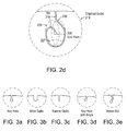
- weak areas include, for example, the sides and bottom of the radially inward circular portion of keyhole gullets having a neck portion that opens into a circle portion (such as shown in Figures 3a, 3d, and 3e ).
- the neck portion may be on an angle (as best illustrated in Figure 3d ) or have an arrow-shape (as best illustrated in Figure 3e ).
- weak gullet areas include the radially most inward semi-circle portion of narrow and wide gullets (such as shown in Figures 3b and 3c ). Maximizing the radius at one or more of these weak locations renders the gullet more resistant to fatigue and cracking.
- the short axes of the elliptical shapes are provided along gullet areas where cracks are less likely to start spontaneously.
- the cutout design of the elliptical gullet may vary as well, so long as a long axis of the gullet design is maintained at the known weak areas.
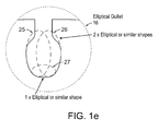
- one embodiment provides a generally open-style drop gullet that has a cutout including a pair of first elliptical shapes, each having its long axis in the radial direction of the blade so as to elongate the gullet sides, and/or a second elliptical shape having its long axis in the axial direction of the blade so as to elongate the gullet bottom (as will be discussed with reference to Figures 1a-e ).
- An alternative embodiment provides a generally slit-style gullet having a slit that essentially traces the outline of the open-style drop gullet previously described (as will be discussed with reference to Figures 2a-d ).
- the term “axial” generally refers to a direction that is substantially parallel to the saw blade's center of rotation.
- the term “radial” generally refers to a direction transverse to the axial direction.
- the elliptical gullet is not limited to any particular type of saw blade. Rather, the elliptical gullets may be implemented with blades having teeth (such as for cutting wood or plastic) or abrasive segments (such as for cutting masonry or other very hard materials). Likewise, the elliptical gullets may be implemented with blades having single layer cores, double layer cores, and sandwich-type cores (e.g., for reducing noise in various cutting applications).
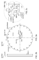
- Figures 1a through 1e illustrate a circular saw blade configured with elliptical gullets.
- the circular saw blade 10 has peripheral cutting elements 12 separated by a series of elliptical gullets 16.
- blade 10 includes a core 21, having an arbor hole 14 through which the blade 10 may be mounted and fastened to the spindle of a circular saw or other suitable machine as conventionally done (e.g., with a threaded fastener).
- the blade 10 may further include a bushing such as described in U.S. Patent Application Publication No. 2006/0185492 , and/or an assembly for accommodating multiple bore sizes such as described in U.S. Patent Application Publication No. 2006/0266176 .
- saw blades configured in accordance with embodiments of the present invention can be used in any number of applications.
- saw blade 10 can be installed on a gasoline powered handheld saw (e.g., STIHL TS760, manufactured by Andreas Stihl AG), and used to dry cut a steel plate.
- saw blade 10 can be installed onto a floor saw (e.g., Clipper CSB1 P13, manufactured by Saint-Gobain SA), and used to wet cut concrete.
- saw blade 10 can be installed onto an automatic, 14 HP (10.3kW) cut-off sawing machine (e.g., HUARD 30V53, manufactured by HUARD), and used to cut a steel or plastic tube.
- HUARD 30V53 manufactured by HUARD
- the core 21 is substantially circular in shape.
- the core includes two discrete outer layers that are mechanically fastened directly to one another (e.g., via welds, rivets, and/or nut-and-bolt arrangement).
- the core 21 may be a sandwich-type core, where two discrete outer layers sandwich an inner layer of noise-damping material such as cork, glue, epoxy or other suitable damping material (e.g., resin, copper, or soft iron).
- the core 21 may be integrally formed through a suitable metrology or molding process (e.g., metal casting, injection molding, hot-pressing, cold-pressing, etc), so long as the elliptical gullets 16 can be provided (e.g., in situ via pressure molding, machined, or otherwise formed).
- the outer layers of core 21, whether they are discrete or integral in nature, may be fabricated from substantially any material having sufficient strength for the cutting application or applications at hand. Examples of suitable core materials include steel, aluminum, titanium, bronze, their composites and alloys, and combinations thereof (e.g., ANSI 4130 steel and aluminum alloys, 2024, 6065 and 7178).
- reinforced plastics or non-metallic composites may be used to construct the core 21.
- the core 21 may have other features, in addition to cutting elements 12 and elliptical gullets 16.
- the core 21 includes one or more perforations 33 extending through the central core, along a circumference disposed concentrically with, and between, the arbor hole 14 and the periphery of blade 10.
- the perforations are arranged to form annular windows through the core 21 that corresponds to a predetermined cutting depth during rotational operation of the blade 10.
- the radially innermost set of perforations 33 form a first annular window corresponding to a first cutting depth
- the radially outermost set of perforations 33 form a second annular window corresponding to a second cutting depth.
- each gullet 16 includes a neck portion 18 defined by parallel side walls extending radially inward from the periphery of the saw blade 10. At the radially inward end of the neck portion 18, the side walls diverge (at about 45°, as best shown in Figure 1d ) from each other to form an arcuate base 20.
- the bottom of base 20 is shaped like the elongated side of elliptical shape 27.
- the left side of base 20 is shaped like the elongated side of elliptical shape 25, and the right side of base 20 is shaped like the elongated side of elliptical shape 26.
- elongating the radii of the gullet at these particular locations improves crack-resistance of blade 10.
- Example dimensions are shown for each of the elliptical shapes embodied (shown in dashed lines) in the design of gullet 16, including the radius for both long and short axes of each.
- the elliptical gullets 16 effectively enlarges the radii in the known weak gullet areas, relative to radii in the non-weak gullet areas.
- the cutting elements 12 may take the form of abrasive-laden segments spaced along the periphery or the core 21.
- the segments may include, for example, superabrasive grains suspended in a metal bond that is brazed or otherwise secured to the periphery or the core 21.
- a superabrasive tool may be manufactured by mixing superabrasive particles such as diamond and cubic boron nitride (cBN) with a suitable metal bond such as iron, copper, and tin. The mixture is then compressed in a mold to form the desired shape (e.g., segment having the desired width, length, and curvature).
- the 'green' form is then sintered at a suitable temperature to form a bonded segment with a plurality of superabrasive particles disposed therein.
- the segment is attached (e.g., by brazing, arc welding, or laser bonding) to the perimeter of core 21.
- abrasive segments can be lengthened, in proportion to the blade diameter, to reduce the number of segments, improve fracture/bend resistance, and reduce manufacturing costs.
- the ratio of abrasive segment length to blade diameter is a minimum of 0.2.
- abrasive segments can be used for relatively difficult cutting operations (e.g., for cutting concrete, asphalt, stone, and other hard materials).
- saw blade 10 may be provided with cutting elements 12 in the form of teeth, such as typical of a wide range of circular saw blades intended for cutting relatively soft materials such as wood, plastic, and the like.
- the teeth may be of any size and shape.
- the teeth may be provided with conventional hardened tips, such as fabricated from tungsten carbide, and/or may be provided with the abrasive grain bonded thereto.
- saw blade 10 is provided with a plurality of teeth having a single layer of abrasive grains chemically bonded to at least a portion of each tooth, as described in U.S. Patent Nos. 6,817,936 and 6,935,940 .
- saw blade 10 may be provided with cutting elements 12 in the form of a single layer of abrasive grain that is brazed, electroplated, or otherwise attached to the periphery of the core 21 (as opposed to attaching bonded segments or providing teeth at the perimeter).
- cutting elements 12 in the form of a single layer of abrasive grain that is brazed, electroplated, or otherwise attached to the periphery of the core 21 (as opposed to attaching bonded segments or providing teeth at the perimeter).
- Numerous cutting element 12 configurations and materials can be used in embodiments of the present invention, as will be apparent in light of this disclosure. The present invention is not intended to be limited to any particular cutting element configuration or scheme.
- Example dimensions are also shown in Figures 1a through 1e . These dimensions are merely provided as one specific example embodiment that can be fabricated. However, it will be readily apparent in light of this disclosure that numerous dimensions, as well as elliptical gullet configurations can be used to implement a saw blade in accordance with an embodiment of the present invention. The present invention is not intended to be limited to any particular set or range of blade dimensions or configurations. Rather, embodiments of the present invention are intended to cover any saw blade that can be implemented for its intended purpose and configured with elliptical gullets as described herein.
- FIGS 2a through 2e illustrate a circular saw blade configured with elliptical gullets, in accordance with another embodiment of the present invention.
- the circular saw blade 10 has a core 21 with peripheral cutting elements 12 separated by a series of elliptical gullets 216.
- the previous discussion with reference to Figures 1a through 1e including discussion relevant to cutting elements 12 and core 21, is equally applicable here, as is the general discussion relevant to elliptical gullets 16 (including example dimensions) and saw blade 10.
- the main difference of the embodiment shown in Figures 2a through 2d is the design of elliptical gullets 216. Other differences, such as the lack of a cutting depth gauge formed of perforations 33 and dimensional qualities, will be apparent.
- each gullet 216 of this example embodiment includes a slit 218 that extends radially inward from the periphery of the saw blade 10, and essentially beginning at the center of what would be the neck portion 18 of the gullet 16 design.
- the slit 218 diverges to the right (at about 45°, as best shown in Figure 2c ) and essentially traces the outline of what would be the arcuate base 20 of the gullet 16 design. At the end of the trace, slit 218 turns inward and terminates at a circular endpoint 220.
- the width (kerf) of the slit can be, for example, in the range of 50 microns to 5 millimeters (the embodiment shown is about 1 millimeter).
- the bottom of the trace formed by slit 218 is shaped like the elongated side of elliptical shape 227.
- the left side of the trace formed by slit 218 is shaped like the elongated side of elliptical shape 225, and the right side of the trace formed by slit 218 is shaped like the elongated side of elliptical shape 226.
- this gullet 216 employs elongated radii at known weak locations (bottom and sides of gullet) to improve crack-resistance of blade 10.
- Example dimensions are shown for each of the elliptical shapes embodied (shown in dashed lines) in the design of gullet 216, including the radius for both long and short axes of each.
- the elliptical gullets 216 enlarges the radii in the known weak gullet areas, relative to radii in the non-weak gullet areas.
Landscapes
- Engineering & Computer Science (AREA)
- Mechanical Engineering (AREA)
- Processing Of Stones Or Stones Resemblance Materials (AREA)
- Polishing Bodies And Polishing Tools (AREA)
Claims (13)
- Kreissägeblatt (10), umfassend:einen runden Kern (21) mit einer ersten flachen Seite und einer zweiten flachen Seite, einer mittigen Bohrung (14) und einem Außenumfang;eine Vielzahl von Schneidelementen (12) am Außenumfang des Kerns (21); und eine oder mehrere Kerben (16), die sich sternförmig vom Umfang des Kerns (21) nach Innen erstrecken, wobei jede Kerbe (16) eine Form hat, die mindestens einen verlängerten Bogen umfasst, der die Radien im Bereich der Kerbe, die im Verhältnis zu anderen Kerbbereichen anfällig für Risse sind, erweitert, dadurch charakterisiert, dass
die Form der Kerbe (16) zwei gebogene Seiten umfasst, wobei jede Seite mit einer sternförmig nach innen gebogener Unterseite verbunden ist, und wobei die Unterseite wie die verlängerte Seite einer ersten elliptischen Form (27) geformt ist, und wobei jede der beiden Seiten wie die verlängerte Seite einer zweiten elliptischen Form (25, 26) geformt ist. - Kreissägeblatt (10) nach Anspruch 1, wobei die erste elliptische Form (27) kurze und lange Achsen hat, die beide kürzer sind als die entsprechenden kurzen und langen Achsen der zweiten elliptischen Form (25, 26).
- Kreissägeblatt (10) nach Anspruch 1, wobei der Kern (21) zwei oder mehrere Schichten umfasst, die wirksam über mindestens entweder ein Bindungsmaterial oder einen mechanischen Verschluss verbunden sind.
- Kreissägeblatt (10) nach Anspruch 3, wobei der Kern (21) ein Kern in Sandwichbauweise ist, der eine mittlere Schicht aus schalldämmendem Material umfasst und zwischen der ersten und zweiten flachen Seite eingebunden ist.
- Kreissägeblatt (10) nach Anspruch 1, wobei der Kern (21) aus nicht-metallischem Material oder Stahl besteht.
- Kreissägeblatt (10) nach Anspruch 1, wobei die Schneidelemente (12) mindestens entweder verbundene Schleifsegmente, eine einzelne Schicht Schleifmittel oder Zähne umfassen.
- Kreissägeblatt (10) nach Anspruch 1, wobei sich zwischen den angrenzenden Schneidelementen (12) mindestens eine Kerbe (16) befindet.
- Kreissägeblatt (10) nach Anspruch 1, wobei jede Kerbe (16) drei oder mehrere elliptische Formen (25, 26, 27) umfasst, die zu drei verschiedenen Kerbbereichen gehören.
- Kreissägeblatt (10) nach Anspruch 1 oder 2, wobei mindestens eine der ersten und der zweiten elliptischen Formen (25, 26, 27) asymmetrisch zu mindestens einer ihrer langen und kurzen Achsen ist.
- Kreissägeblatt (10), umfassend:einen runden Kern (21) mit einer ersten flachen Seite und einer zweiten flachen Seite, eine mittigen Bohrung (14);eine Vielzahl von Schneidelementen (12) am Außenumfang des Kerns (21); und einer oder mehreren Kerben (16), die sich sternförmig vom Umfang des Kerns (21) nach Innen erstrecken, wobei jede Kerbe (14) eine Form hat, die mindestens drei oder mehrere elliptische Formen (25, 26, 27) umfasst, die den drei unterschiedlichen Kerbbereichen entsprechen und dabei die Radien dieser Kerbbereiche relativ zu den anderen Kerbbereichen erweitern, dadurch charakterisiert, dass
die Form der Kerbe (16) zwei gebogene Seiten umfasst, wobei jede Seite mit einem sternförmig nach innen gebogener Unterseite verbunden ist, und wobei die Unterseite wie die verlängerte Seite einer ersten elliptischen Form (27) geformt ist, und wobei jede der beiden Seiten wie die verlängerte Seite einer zweiten elliptischen Form (25, 26) geformt ist. - Kreissägeblatt (10) nach Anspruch 1, 2 oder 10, wobei die Kerbe (16) eine Öffnung umfasst, die die beiden Seiten und die Unterseite oder einen Schlitz (218) definiert, der die beiden Seiten und die Unterseite definiert.
- Kreissägeblatt (10) nach Anspruch 1, 2 oder 10, wobei die elliptischen Formen (25, 26, 27) symmetrisch zu ihren entsprechenden langen und kurzen Achsen sind.
- Kreissägeblatt (10) nach Anspruch 10, wobei mindestens eine der elliptischen Formen (25, 26, 27) asymmetrisch zu mindestens einer ihrer langen und kurzen Achsen ist.
Priority Applications (1)
| Application Number | Priority Date | Filing Date | Title |
|---|---|---|---|
| PL09703608T PL2244853T3 (pl) | 2008-01-22 | 2009-01-21 | Tarcza piły z elipsoidalnymi wrębami |
Applications Claiming Priority (2)
| Application Number | Priority Date | Filing Date | Title |
|---|---|---|---|
| US1180608P | 2008-01-22 | 2008-01-22 | |
| PCT/US2009/031548 WO2009094378A1 (en) | 2008-01-22 | 2009-01-21 | Circular saw blade with elliptical gullets |
Publications (3)
| Publication Number | Publication Date |
|---|---|
| EP2244853A1 EP2244853A1 (de) | 2010-11-03 |
| EP2244853A4 EP2244853A4 (de) | 2014-09-24 |
| EP2244853B1 true EP2244853B1 (de) | 2015-09-30 |
Family
ID=40901417
Family Applications (1)
| Application Number | Title | Priority Date | Filing Date |
|---|---|---|---|
| EP09703608.1A Active EP2244853B1 (de) | 2008-01-22 | 2009-01-21 | Kreissägeblatt mit ellipsenförmigen kerben |
Country Status (9)
| Country | Link |
|---|---|
| EP (1) | EP2244853B1 (de) |
| JP (2) | JP2011509853A (de) |
| CN (1) | CN101970163B (de) |
| AU (1) | AU2009206493B2 (de) |
| BR (1) | BRPI0906499B1 (de) |
| DK (1) | DK2244853T3 (de) |
| ES (1) | ES2556953T3 (de) |
| PL (1) | PL2244853T3 (de) |
| WO (1) | WO2009094378A1 (de) |
Families Citing this family (7)
| Publication number | Priority date | Publication date | Assignee | Title |
|---|---|---|---|---|
| US10814414B2 (en) | 2015-11-02 | 2020-10-27 | Milwaukee Electric Tool Corporation | Saw blade |
| CN114985838A (zh) * | 2017-05-18 | 2022-09-02 | 米沃奇电动工具公司 | 锯片及其制造方法 |
| JP6903528B2 (ja) * | 2017-09-08 | 2021-07-14 | 株式会社ノリタケカンパニーリミテド | 切断ブレード |
| CN107598275A (zh) * | 2017-09-22 | 2018-01-19 | 张家港沙工科技服务有限公司 | 一种切割机圆盘锯片 |
| CN108004444A (zh) * | 2017-12-19 | 2018-05-08 | 苏州中骏木工机械配件有限公司 | 一种螺旋刀头用刀片 |
| CN108015860A (zh) * | 2017-12-20 | 2018-05-11 | 苏州中骏木工机械配件有限公司 | 一种耐高温木工刀具 |
| CN109302908A (zh) * | 2018-11-19 | 2019-02-05 | 国网冀北电力有限公司张家口供电公司 | 具有涡轮树脂大扭矩电动马达的绝缘高枝锯 |
Family Cites Families (27)
| Publication number | Priority date | Publication date | Assignee | Title |
|---|---|---|---|---|
| IT1104926B (it) * | 1978-07-28 | 1985-10-28 | Gomex Verktyg Ab | Lama di sega circolare |
| US4705017A (en) * | 1985-08-19 | 1987-11-10 | Federal-Mogul Corporation | Stress resistant abrasive cutting wheel |
| JPS6347067A (ja) * | 1986-08-11 | 1988-02-27 | Osaka Daiyamondo Kogyo Kk | 研削工具およびその製造法 |
| JPH0620562Y2 (ja) * | 1987-06-11 | 1994-06-01 | 天龍製鋸株式会社 | 回転鋸用基板の騒音防止装置 |
| JPH036901U (de) * | 1989-06-07 | 1991-01-23 | ||
| JPH0463682A (ja) * | 1990-07-04 | 1992-02-28 | N K Koki Kk | ダイヤモンドサーキュラーソー |
| JPH04152069A (ja) * | 1990-10-15 | 1992-05-26 | Toshiba Corp | メタルボンド工具およびその製造方法 |
| JPH06226638A (ja) * | 1993-02-02 | 1994-08-16 | Nippon Chuzo Kk | ダイヤモンドブレード |
| DE9400182U1 (de) * | 1994-01-10 | 1994-03-10 | Ledermann Gmbh, 72160 Horb | Kreissägeblatt |
| US5518443A (en) | 1994-05-13 | 1996-05-21 | Norton Company | Superabrasive tool |
| JPH0847816A (ja) * | 1994-08-03 | 1996-02-20 | Hashimoto Tokushu Kogyo Kk | 丸 鋸 |
| TW316868B (de) | 1994-12-28 | 1997-10-01 | Norton Co | |
| JPH08229732A (ja) * | 1995-02-28 | 1996-09-10 | Toshio Aono | 鋸刃用曲線スリット |
| KR100329309B1 (ko) | 1996-03-15 | 2002-08-24 | 생-고뱅 어브레이시브즈, 인코포레이티드 | 연마절삭공구및연마절삭방법 |
| US5868125A (en) | 1996-11-21 | 1999-02-09 | Norton Company | Crenelated abrasive tool |
| JP2000246651A (ja) * | 1999-02-26 | 2000-09-12 | Toho Titanium Co Ltd | ダイヤモンドソーブレード |
| JP3444819B2 (ja) * | 1999-07-05 | 2003-09-08 | 株式会社ノリタケスーパーアブレーシブ | 回転円盤砥石 |
| AU2001250916A1 (en) * | 2000-03-21 | 2001-10-03 | American Tool Companies, Inc. | Metal-cutting saw blade having strengthened gullet and negative tooth rake |
| KR100440869B1 (ko) * | 2001-02-19 | 2004-07-19 | 이화다이아몬드공업 주식회사 | 절단용 톱판 |
| US6681674B2 (en) * | 2001-02-23 | 2004-01-27 | William Hakansson | Band saw blade |
| DE10124687B4 (de) * | 2001-05-18 | 2006-01-12 | Leitz Gmbh & Co. Kg | Kreissägeblatt |
| US20060185492A1 (en) | 2005-02-18 | 2006-08-24 | Francois Chianese | Shoulder bushing for saw blades |
| US7210474B2 (en) | 2005-03-23 | 2007-05-01 | Saint-Gobain Abrasives Technology Company | Saw blade with cutting depth gauge |
| US7946907B2 (en) * | 2005-04-20 | 2011-05-24 | Saint-Gobain Abrasives, Inc. | Saw blade gullet configuration |
| US7444914B2 (en) | 2005-05-25 | 2008-11-04 | Saint-Gobain Abrasives Technology Company | Saw blade with multiple bore sizes |
| JP2007160416A (ja) * | 2005-12-09 | 2007-06-28 | Hitachi Koki Co Ltd | 切断ブレード |
| CN2905291Y (zh) * | 2006-04-14 | 2007-05-30 | 浙江工业大学 | 锯片 |
-
2009
- 2009-01-21 DK DK09703608.1T patent/DK2244853T3/en active
- 2009-01-21 ES ES09703608.1T patent/ES2556953T3/es active Active
- 2009-01-21 EP EP09703608.1A patent/EP2244853B1/de active Active
- 2009-01-21 WO PCT/US2009/031548 patent/WO2009094378A1/en not_active Ceased
- 2009-01-21 CN CN2009801028016A patent/CN101970163B/zh active Active
- 2009-01-21 PL PL09703608T patent/PL2244853T3/pl unknown
- 2009-01-21 JP JP2010543308A patent/JP2011509853A/ja active Pending
- 2009-01-21 AU AU2009206493A patent/AU2009206493B2/en not_active Ceased
- 2009-01-21 BR BRPI0906499-0A patent/BRPI0906499B1/pt active IP Right Grant
-
2012
- 2012-10-24 JP JP2012235203A patent/JP5739853B2/ja not_active Expired - Fee Related
Also Published As
| Publication number | Publication date |
|---|---|
| PL2244853T3 (pl) | 2016-03-31 |
| ES2556953T3 (es) | 2016-01-21 |
| BRPI0906499B1 (pt) | 2020-10-13 |
| EP2244853A4 (de) | 2014-09-24 |
| JP2013018118A (ja) | 2013-01-31 |
| JP5739853B2 (ja) | 2015-06-24 |
| AU2009206493A1 (en) | 2009-07-30 |
| CN101970163B (zh) | 2013-10-23 |
| BRPI0906499A2 (pt) | 2015-07-14 |
| AU2009206493B2 (en) | 2011-12-01 |
| WO2009094378A1 (en) | 2009-07-30 |
| EP2244853A1 (de) | 2010-11-03 |
| CN101970163A (zh) | 2011-02-09 |
| DK2244853T3 (en) | 2016-01-11 |
| JP2011509853A (ja) | 2011-03-31 |
Similar Documents
| Publication | Publication Date | Title |
|---|---|---|
| US20090199693A1 (en) | Circular Saw Blade With Elliptical Gullets | |
| EP2296839B1 (de) | Kreissägeblatt mit versetzten zahngründen | |
| CA2605392C (en) | Saw blade | |
| EP2244853B1 (de) | Kreissägeblatt mit ellipsenförmigen kerben | |
| EP2651601B1 (de) | Schlitzverschleissindikator für ein schleifwerkzeug | |
| WO2004078440A1 (en) | Gear type machining tip and tool attaching the same thereon | |
| US6739227B2 (en) | Apparatus and method for providing an enhanced metal cutting saw blade | |
| EP1726393B1 (de) | Kreissägeblatt mit mehrfachen Zentralbohrergrößen | |
| AU2011204845B2 (en) | Circular saw blade with offset gullets | |
| JP2015166128A (ja) | 研削工具用のスロット型磨耗指標 |
Legal Events
| Date | Code | Title | Description |
|---|---|---|---|
| PUAI | Public reference made under article 153(3) epc to a published international application that has entered the european phase |
Free format text: ORIGINAL CODE: 0009012 |
|
| 17P | Request for examination filed |
Effective date: 20100817 |
|
| AK | Designated contracting states |
Kind code of ref document: A1 Designated state(s): AT BE BG CH CY CZ DE DK EE ES FI FR GB GR HR HU IE IS IT LI LT LU LV MC MK MT NL NO PL PT RO SE SI SK TR |
|
| AX | Request for extension of the european patent |
Extension state: AL BA RS |
|
| RIN1 | Information on inventor provided before grant (corrected) |
Inventor name: HEYEN, ANDRE R. G. |
|
| DAX | Request for extension of the european patent (deleted) | ||
| A4 | Supplementary search report drawn up and despatched |
Effective date: 20140827 |
|
| RIC1 | Information provided on ipc code assigned before grant |
Ipc: B27B 33/00 20060101ALI20140821BHEP Ipc: B23D 61/02 20060101AFI20140821BHEP Ipc: B27B 33/08 20060101ALI20140821BHEP Ipc: B23D 61/00 20060101ALI20140821BHEP |
|
| GRAP | Despatch of communication of intention to grant a patent |
Free format text: ORIGINAL CODE: EPIDOSNIGR1 |
|
| INTG | Intention to grant announced |
Effective date: 20150430 |
|
| GRAS | Grant fee paid |
Free format text: ORIGINAL CODE: EPIDOSNIGR3 |
|
| GRAA | (expected) grant |
Free format text: ORIGINAL CODE: 0009210 |
|
| AK | Designated contracting states |
Kind code of ref document: B1 Designated state(s): AT BE BG CH CY CZ DE DK EE ES FI FR GB GR HR HU IE IS IT LI LT LU LV MC MK MT NL NO PL PT RO SE SI SK TR |
|
| REG | Reference to a national code |
Ref country code: CH Ref legal event code: EP Ref country code: GB Ref legal event code: FG4D |
|
| REG | Reference to a national code |
Ref country code: AT Ref legal event code: REF Ref document number: 752096 Country of ref document: AT Kind code of ref document: T Effective date: 20151015 |
|
| REG | Reference to a national code |
Ref country code: IE Ref legal event code: FG4D |
|
| REG | Reference to a national code |
Ref country code: DE Ref legal event code: R096 Ref document number: 602009033905 Country of ref document: DE |
|
| REG | Reference to a national code |
Ref country code: FR Ref legal event code: PLFP Year of fee payment: 8 |
|
| REG | Reference to a national code |
Ref country code: SE Ref legal event code: TRGR |
|
| REG | Reference to a national code |
Ref country code: DK Ref legal event code: T3 Effective date: 20160107 |
|
| REG | Reference to a national code |
Ref country code: ES Ref legal event code: FG2A Ref document number: 2556953 Country of ref document: ES Kind code of ref document: T3 Effective date: 20160121 |
|
| PG25 | Lapsed in a contracting state [announced via postgrant information from national office to epo] |
Ref country code: LV Free format text: LAPSE BECAUSE OF FAILURE TO SUBMIT A TRANSLATION OF THE DESCRIPTION OR TO PAY THE FEE WITHIN THE PRESCRIBED TIME-LIMIT Effective date: 20150930 Ref country code: GR Free format text: LAPSE BECAUSE OF FAILURE TO SUBMIT A TRANSLATION OF THE DESCRIPTION OR TO PAY THE FEE WITHIN THE PRESCRIBED TIME-LIMIT Effective date: 20151231 Ref country code: FI Free format text: LAPSE BECAUSE OF FAILURE TO SUBMIT A TRANSLATION OF THE DESCRIPTION OR TO PAY THE FEE WITHIN THE PRESCRIBED TIME-LIMIT Effective date: 20150930 Ref country code: LT Free format text: LAPSE BECAUSE OF FAILURE TO SUBMIT A TRANSLATION OF THE DESCRIPTION OR TO PAY THE FEE WITHIN THE PRESCRIBED TIME-LIMIT Effective date: 20150930 |
|
| REG | Reference to a national code |
Ref country code: NL Ref legal event code: MP Effective date: 20150930 |
|
| REG | Reference to a national code |
Ref country code: NO Ref legal event code: T2 Effective date: 20150930 |
|
| REG | Reference to a national code |
Ref country code: LT Ref legal event code: MG4D |
|
| PG25 | Lapsed in a contracting state [announced via postgrant information from national office to epo] |
Ref country code: HR Free format text: LAPSE BECAUSE OF FAILURE TO SUBMIT A TRANSLATION OF THE DESCRIPTION OR TO PAY THE FEE WITHIN THE PRESCRIBED TIME-LIMIT Effective date: 20150930 |
|
| PG25 | Lapsed in a contracting state [announced via postgrant information from national office to epo] |
Ref country code: EE Free format text: LAPSE BECAUSE OF FAILURE TO SUBMIT A TRANSLATION OF THE DESCRIPTION OR TO PAY THE FEE WITHIN THE PRESCRIBED TIME-LIMIT Effective date: 20150930 Ref country code: NL Free format text: LAPSE BECAUSE OF FAILURE TO SUBMIT A TRANSLATION OF THE DESCRIPTION OR TO PAY THE FEE WITHIN THE PRESCRIBED TIME-LIMIT Effective date: 20150930 Ref country code: SK Free format text: LAPSE BECAUSE OF FAILURE TO SUBMIT A TRANSLATION OF THE DESCRIPTION OR TO PAY THE FEE WITHIN THE PRESCRIBED TIME-LIMIT Effective date: 20150930 Ref country code: IS Free format text: LAPSE BECAUSE OF FAILURE TO SUBMIT A TRANSLATION OF THE DESCRIPTION OR TO PAY THE FEE WITHIN THE PRESCRIBED TIME-LIMIT Effective date: 20160130 |
|
| PG25 | Lapsed in a contracting state [announced via postgrant information from national office to epo] |
Ref country code: PT Free format text: LAPSE BECAUSE OF FAILURE TO SUBMIT A TRANSLATION OF THE DESCRIPTION OR TO PAY THE FEE WITHIN THE PRESCRIBED TIME-LIMIT Effective date: 20160201 Ref country code: RO Free format text: LAPSE BECAUSE OF FAILURE TO SUBMIT A TRANSLATION OF THE DESCRIPTION OR TO PAY THE FEE WITHIN THE PRESCRIBED TIME-LIMIT Effective date: 20150930 |
|
| REG | Reference to a national code |
Ref country code: DE Ref legal event code: R097 Ref document number: 602009033905 Country of ref document: DE |
|
| PLBE | No opposition filed within time limit |
Free format text: ORIGINAL CODE: 0009261 |
|
| STAA | Information on the status of an ep patent application or granted ep patent |
Free format text: STATUS: NO OPPOSITION FILED WITHIN TIME LIMIT |
|
| PG25 | Lapsed in a contracting state [announced via postgrant information from national office to epo] |
Ref country code: LU Free format text: LAPSE BECAUSE OF FAILURE TO SUBMIT A TRANSLATION OF THE DESCRIPTION OR TO PAY THE FEE WITHIN THE PRESCRIBED TIME-LIMIT Effective date: 20160121 |
|
| REG | Reference to a national code |
Ref country code: CH Ref legal event code: PL |
|
| 26N | No opposition filed |
Effective date: 20160701 |
|
| PG25 | Lapsed in a contracting state [announced via postgrant information from national office to epo] |
Ref country code: MC Free format text: LAPSE BECAUSE OF FAILURE TO SUBMIT A TRANSLATION OF THE DESCRIPTION OR TO PAY THE FEE WITHIN THE PRESCRIBED TIME-LIMIT Effective date: 20150930 |
|
| PG25 | Lapsed in a contracting state [announced via postgrant information from national office to epo] |
Ref country code: CH Free format text: LAPSE BECAUSE OF NON-PAYMENT OF DUE FEES Effective date: 20160131 Ref country code: LI Free format text: LAPSE BECAUSE OF NON-PAYMENT OF DUE FEES Effective date: 20160131 |
|
| REG | Reference to a national code |
Ref country code: IE Ref legal event code: MM4A |
|
| PG25 | Lapsed in a contracting state [announced via postgrant information from national office to epo] |
Ref country code: SI Free format text: LAPSE BECAUSE OF FAILURE TO SUBMIT A TRANSLATION OF THE DESCRIPTION OR TO PAY THE FEE WITHIN THE PRESCRIBED TIME-LIMIT Effective date: 20150930 |
|
| REG | Reference to a national code |
Ref country code: FR Ref legal event code: PLFP Year of fee payment: 9 |
|
| PG25 | Lapsed in a contracting state [announced via postgrant information from national office to epo] |
Ref country code: IE Free format text: LAPSE BECAUSE OF NON-PAYMENT OF DUE FEES Effective date: 20160121 |
|
| PG25 | Lapsed in a contracting state [announced via postgrant information from national office to epo] |
Ref country code: MT Free format text: LAPSE BECAUSE OF FAILURE TO SUBMIT A TRANSLATION OF THE DESCRIPTION OR TO PAY THE FEE WITHIN THE PRESCRIBED TIME-LIMIT Effective date: 20150930 |
|
| REG | Reference to a national code |
Ref country code: AT Ref legal event code: UEP Ref document number: 752096 Country of ref document: AT Kind code of ref document: T Effective date: 20150930 |
|
| REG | Reference to a national code |
Ref country code: FR Ref legal event code: PLFP Year of fee payment: 10 |
|
| PG25 | Lapsed in a contracting state [announced via postgrant information from national office to epo] |
Ref country code: HU Free format text: LAPSE BECAUSE OF FAILURE TO SUBMIT A TRANSLATION OF THE DESCRIPTION OR TO PAY THE FEE WITHIN THE PRESCRIBED TIME-LIMIT; INVALID AB INITIO Effective date: 20090121 Ref country code: CY Free format text: LAPSE BECAUSE OF FAILURE TO SUBMIT A TRANSLATION OF THE DESCRIPTION OR TO PAY THE FEE WITHIN THE PRESCRIBED TIME-LIMIT Effective date: 20150930 |
|
| PG25 | Lapsed in a contracting state [announced via postgrant information from national office to epo] |
Ref country code: MT Free format text: LAPSE BECAUSE OF FAILURE TO SUBMIT A TRANSLATION OF THE DESCRIPTION OR TO PAY THE FEE WITHIN THE PRESCRIBED TIME-LIMIT Effective date: 20160131 Ref country code: TR Free format text: LAPSE BECAUSE OF FAILURE TO SUBMIT A TRANSLATION OF THE DESCRIPTION OR TO PAY THE FEE WITHIN THE PRESCRIBED TIME-LIMIT Effective date: 20150930 Ref country code: MK Free format text: LAPSE BECAUSE OF FAILURE TO SUBMIT A TRANSLATION OF THE DESCRIPTION OR TO PAY THE FEE WITHIN THE PRESCRIBED TIME-LIMIT Effective date: 20150930 |
|
| PG25 | Lapsed in a contracting state [announced via postgrant information from national office to epo] |
Ref country code: BG Free format text: LAPSE BECAUSE OF FAILURE TO SUBMIT A TRANSLATION OF THE DESCRIPTION OR TO PAY THE FEE WITHIN THE PRESCRIBED TIME-LIMIT Effective date: 20150930 |
|
| P01 | Opt-out of the competence of the unified patent court (upc) registered |
Effective date: 20230530 |
|
| PGFP | Annual fee paid to national office [announced via postgrant information from national office to epo] |
Ref country code: NO Payment date: 20231221 Year of fee payment: 16 Ref country code: DK Payment date: 20231219 Year of fee payment: 16 Ref country code: CZ Payment date: 20231227 Year of fee payment: 16 |
|
| PGFP | Annual fee paid to national office [announced via postgrant information from national office to epo] |
Ref country code: PL Payment date: 20231221 Year of fee payment: 16 |
|
| PGFP | Annual fee paid to national office [announced via postgrant information from national office to epo] |
Ref country code: ES Payment date: 20240202 Year of fee payment: 16 |
|
| PGFP | Annual fee paid to national office [announced via postgrant information from national office to epo] |
Ref country code: IT Payment date: 20240102 Year of fee payment: 16 |
|
| REG | Reference to a national code |
Ref country code: DK Ref legal event code: EBP Effective date: 20250131 |
|
| PG25 | Lapsed in a contracting state [announced via postgrant information from national office to epo] |
Ref country code: NO Free format text: LAPSE BECAUSE OF NON-PAYMENT OF DUE FEES Effective date: 20250131 |
|
| PG25 | Lapsed in a contracting state [announced via postgrant information from national office to epo] |
Ref country code: CZ Free format text: LAPSE BECAUSE OF NON-PAYMENT OF DUE FEES Effective date: 20250121 |
|
| PGFP | Annual fee paid to national office [announced via postgrant information from national office to epo] |
Ref country code: GB Payment date: 20251219 Year of fee payment: 18 |
|
| PG25 | Lapsed in a contracting state [announced via postgrant information from national office to epo] |
Ref country code: DK Free format text: LAPSE BECAUSE OF NON-PAYMENT OF DUE FEES Effective date: 20250131 |
|
| PG25 | Lapsed in a contracting state [announced via postgrant information from national office to epo] |
Ref country code: IT Free format text: LAPSE BECAUSE OF NON-PAYMENT OF DUE FEES Effective date: 20250121 |
|
| PGFP | Annual fee paid to national office [announced via postgrant information from national office to epo] |
Ref country code: FR Payment date: 20251217 Year of fee payment: 18 |
|
| PGFP | Annual fee paid to national office [announced via postgrant information from national office to epo] |
Ref country code: BE Payment date: 20251217 Year of fee payment: 18 |
|
| PGFP | Annual fee paid to national office [announced via postgrant information from national office to epo] |
Ref country code: SE Payment date: 20251217 Year of fee payment: 18 |
|
| REG | Reference to a national code |
Ref country code: ES Ref legal event code: FD2A Effective date: 20260227 |
|
| PG25 | Lapsed in a contracting state [announced via postgrant information from national office to epo] |
Ref country code: ES Free format text: LAPSE BECAUSE OF NON-PAYMENT OF DUE FEES Effective date: 20250122 |
|
| PGFP | Annual fee paid to national office [announced via postgrant information from national office to epo] |
Ref country code: DE Payment date: 20251217 Year of fee payment: 18 |
|
| PGFP | Annual fee paid to national office [announced via postgrant information from national office to epo] |
Ref country code: AT Payment date: 20251218 Year of fee payment: 18 |