EP2244399B1 - Dispositif de station de base, dispositif de terminal et système de communication sans fil - Google Patents
Dispositif de station de base, dispositif de terminal et système de communication sans fil Download PDFInfo
- Publication number
- EP2244399B1 EP2244399B1 EP09709292.8A EP09709292A EP2244399B1 EP 2244399 B1 EP2244399 B1 EP 2244399B1 EP 09709292 A EP09709292 A EP 09709292A EP 2244399 B1 EP2244399 B1 EP 2244399B1
- Authority
- EP
- European Patent Office
- Prior art keywords
- terminal device
- transmission
- signal
- interference cancellation
- data
- Prior art date
- Legal status (The legal status is an assumption and is not a legal conclusion. Google has not performed a legal analysis and makes no representation as to the accuracy of the status listed.)
- Active
Links
Images


Classifications
-
- H—ELECTRICITY
- H04—ELECTRIC COMMUNICATION TECHNIQUE
- H04B—TRANSMISSION
- H04B7/00—Radio transmission systems, i.e. using radiation field
- H04B7/02—Diversity systems; Multi-antenna system, i.e. transmission or reception using multiple antennas
- H04B7/04—Diversity systems; Multi-antenna system, i.e. transmission or reception using multiple antennas using two or more spaced independent antennas
- H04B7/0413—MIMO systems
- H04B7/0452—Multi-user MIMO systems
-
- H—ELECTRICITY
- H04—ELECTRIC COMMUNICATION TECHNIQUE
- H04B—TRANSMISSION
- H04B7/00—Radio transmission systems, i.e. using radiation field
- H04B7/02—Diversity systems; Multi-antenna system, i.e. transmission or reception using multiple antennas
- H04B7/022—Site diversity; Macro-diversity
- H04B7/026—Co-operative diversity, e.g. using fixed or mobile stations as relays
-
- H—ELECTRICITY
- H04—ELECTRIC COMMUNICATION TECHNIQUE
- H04B—TRANSMISSION
- H04B7/00—Radio transmission systems, i.e. using radiation field
- H04B7/02—Diversity systems; Multi-antenna system, i.e. transmission or reception using multiple antennas
- H04B7/04—Diversity systems; Multi-antenna system, i.e. transmission or reception using multiple antennas using two or more spaced independent antennas
- H04B7/0413—MIMO systems
- H04B7/0426—Power distribution
- H04B7/0434—Power distribution using multiple eigenmodes
-
- H—ELECTRICITY
- H04—ELECTRIC COMMUNICATION TECHNIQUE
- H04B—TRANSMISSION
- H04B7/00—Radio transmission systems, i.e. using radiation field
- H04B7/02—Diversity systems; Multi-antenna system, i.e. transmission or reception using multiple antennas
- H04B7/04—Diversity systems; Multi-antenna system, i.e. transmission or reception using multiple antennas using two or more spaced independent antennas
- H04B7/06—Diversity systems; Multi-antenna system, i.e. transmission or reception using multiple antennas using two or more spaced independent antennas at the transmitting station
- H04B7/0697—Diversity systems; Multi-antenna system, i.e. transmission or reception using multiple antennas using two or more spaced independent antennas at the transmitting station using spatial multiplexing
-
- H—ELECTRICITY
- H04—ELECTRIC COMMUNICATION TECHNIQUE
- H04L—TRANSMISSION OF DIGITAL INFORMATION, e.g. TELEGRAPHIC COMMUNICATION
- H04L25/00—Baseband systems
- H04L25/02—Details ; arrangements for supplying electrical power along data transmission lines
- H04L25/0202—Channel estimation
- H04L25/0224—Channel estimation using sounding signals
- H04L25/0228—Channel estimation using sounding signals with direct estimation from sounding signals
-
- H—ELECTRICITY
- H04—ELECTRIC COMMUNICATION TECHNIQUE
- H04L—TRANSMISSION OF DIGITAL INFORMATION, e.g. TELEGRAPHIC COMMUNICATION
- H04L25/00—Baseband systems
- H04L25/02—Details ; arrangements for supplying electrical power along data transmission lines
- H04L25/03—Shaping networks in transmitter or receiver, e.g. adaptive shaping networks
- H04L25/03006—Arrangements for removing intersymbol interference
- H04L25/03343—Arrangements at the transmitter end
-
- H—ELECTRICITY
- H04—ELECTRIC COMMUNICATION TECHNIQUE
- H04L—TRANSMISSION OF DIGITAL INFORMATION, e.g. TELEGRAPHIC COMMUNICATION
- H04L25/00—Baseband systems
- H04L25/02—Details ; arrangements for supplying electrical power along data transmission lines
- H04L25/03—Shaping networks in transmitter or receiver, e.g. adaptive shaping networks
- H04L25/03006—Arrangements for removing intersymbol interference
- H04L2025/0335—Arrangements for removing intersymbol interference characterised by the type of transmission
- H04L2025/03426—Arrangements for removing intersymbol interference characterised by the type of transmission transmission using multiple-input and multiple-output channels
-
- H—ELECTRICITY
- H04—ELECTRIC COMMUNICATION TECHNIQUE
- H04L—TRANSMISSION OF DIGITAL INFORMATION, e.g. TELEGRAPHIC COMMUNICATION
- H04L25/00—Baseband systems
- H04L25/02—Details ; arrangements for supplying electrical power along data transmission lines
- H04L25/03—Shaping networks in transmitter or receiver, e.g. adaptive shaping networks
- H04L25/03006—Arrangements for removing intersymbol interference
- H04L2025/03777—Arrangements for removing intersymbol interference characterised by the signalling
- H04L2025/03783—Details of reference signals
-
- H—ELECTRICITY
- H04—ELECTRIC COMMUNICATION TECHNIQUE
- H04L—TRANSMISSION OF DIGITAL INFORMATION, e.g. TELEGRAPHIC COMMUNICATION
- H04L25/00—Baseband systems
- H04L25/02—Details ; arrangements for supplying electrical power along data transmission lines
- H04L25/03—Shaping networks in transmitter or receiver, e.g. adaptive shaping networks
- H04L25/03006—Arrangements for removing intersymbol interference
- H04L2025/03777—Arrangements for removing intersymbol interference characterised by the signalling
- H04L2025/03802—Signalling on the reverse channel
-
- H—ELECTRICITY
- H04—ELECTRIC COMMUNICATION TECHNIQUE
- H04W—WIRELESS COMMUNICATION NETWORKS
- H04W72/00—Local resource management
- H04W72/30—Resource management for broadcast services
Definitions
- the present invention relates to a base station device, a terminal device, a wireless communication system, and a wireless communication method for performing wireless communication using space division multiple access.
- An adaptive array antenna (adaptive antenna) is a technique for using space domains.
- An adaptive array antenna adjusts an amplitude and a phase of a reception signal through the use of a weighting coefficient (hereinafter, the weighting coefficient shall be referred to as a "weight") to be multiplied onto the reception signal so as to strongly receive a signal arriving from a desired direction and suppress a signal arriving from a direction of interference waves. Accordingly, a communication capacity of a system can be improved.
- SDMA space division multiple access
- SDM spatial multiplexing
- SDMA technique is described in, for example, " A study on a channel allocation scheme with an adaptive array in SDMA” (T. Ohgane et al., IEEE 47th VTC, Page(s): 725-729, vol. 2 (1997 )).
- SDMA can be implemented if a spatial correlation coefficient between terminal devices is lower than a predetermined value.
- SDMA enables an improvement in throughput and an increase in simultaneous transmission capacity of a wireless communication system.
- a transmitter and a receiver both comprise a plurality of antenna elements and are capable of realizing SDM transmission in a propagation environment where correlation of reception signals between antennas is low.
- the transmitter transmits, for each antenna element, a different data series using a same physical channel.
- the receiver separates and receives reception signals based on different data series received by a plurality of antennas.
- communication capacity can be expanded in proportion to the number of antennas (the transmitter and the receiver have the same number of antennas).
- Multiuser MIMO is a technique that merges the SDMA and SDM techniques described above.
- a multiuser MIMO technique is described in, for example, " Zero-Forcing Methods for Downlink Spatial Multiplexing in Multiuser MIMO channels" (Q. Spencer et al., IEEE Trans. SP, Vol. 52, No. 2, pp. 461-471, 2004 ).
- the multiuser MIMO technique enables space division multiple access due to spatial multiplexing and directionality under a condition where a channel matrix of a concurrently-connected receiver is known by a transmitter.
- WO 2006/080352 discloses an interference cancellation based on a flexibility of an antenna.
- " Multiple Access Interference Cancellation and Link Multiplexing for MIMO Mesh Network” (Sakaguchi et al, Computer Communications and Networks, 2007, ICCN 2007 , Proceedings of the 16th International Conference on Computer Communications and Networks, Honolulu, HI, 2007, pp. 1028-1033 ) discloses techniques for interference cancellation.
- the present invention has been made in consideration of the above, and an object thereof is to provide a wireless communication system that suppresses an interference component superimposed due to the application of DPC in multiuser MIMO. This is achieved by the features of the independent claims.
- a wireless communication system comprises a plurality of terminal devices and a base station device that communicates with a first terminal device and a second terminal device among the plurality of terminal devices over the same channel by spatial multiplexing
- the first terminal device comprises: an interference cancellation coefficient calculator that calculates an interference cancellation coefficient for cancelling interference on a propagation channel between the first terminal device and the base station device; and an interference cancellation coefficient transmitter that transmits the interference cancellation coefficient to the base station device
- the base station device comprises: an interference cancellation coefficient receiver that receives the interference cancellation coefficient from the first terminal device; a control signal transmitter that generates a control signal including a pilot signal based
- the present invention also includes other modes. As such, the disclosure of the present invention is intended to provide a part of the present invention and is not intended to limit the scope of the present invention as described and claimed herein.
- a base station device is a base station device that communicates with a first terminal device and a second terminal device over the same channel by spatial multiplexing, the base station device comprising: an interference cancellation coefficient extractor that extracts an interference cancellation coefficient for cancelling interference on a propagation channel with the second terminal device from a signal received from the first terminal device; a control signal transmitter that generates a control signal including a pilot signal based on the interference cancellation coefficient and transmits the control signal to the terminal devices; an interference canceller that uses the interference cancellation coefficient to cancel an interference component from transmission data to be transmitted to the first terminal device; and a data transmitter that transmits the transmission data, from which the interference component has been canceled by the interference canceller, with transmission data to be transmitted to the second terminal device, over the same channel.
- a terminal device By transmitting a control signal including an interference cancellation coefficient to a terminal device in this manner, a terminal device can appropriately obtain information on a propagation channel with a base station device while taking into consideration a signal component not included in a channel estimate acquired in advance. Accordingly, even in a case where propagation channel information includes an error attributable to the base station device performing, in advance, interference cancellation on a modulated signal to be transmitted, the terminal device can suppress an interference signal from another terminal device to be spatially multiplexed and inhibit reception property degradation. For example, in multiuser MIMO, data transmission efficiency can be enhanced and frequency utilization efficiency can be improved.
- the base station device may further comprise: a transmission weight multiplier that weights a pilot signal used by a terminal device for estimating a propagation channel according to a value of the interference cancellation coefficient; and a dedicated pilot signal generator that generates a dedicated pilot signal obtained by the transmission weight multiplier, wherein the control signal transmitter may transmit the dedicated pilot signal.
- an interference cancellation coefficient can be calculated based on a magnitude of a weight on a dedicated pilot signal, an overhead during data transmission for notifying the interference cancellation coefficient can be reduced.
- the base station device may further comprise: a signal multiplexer that generates a pilot signal formed by multiplexing a control signal for notifying the interference cancellation coefficient and a pilot signal for estimating a propagation channel, wherein the control signal transmitter may transmit a signal generated by the signal multiplexer.
- the signal multiplexer may generate a signal formed by further multiplexing the dedicated pilot signal or a signal formed by multiplexing the control signal subjected to the same weighting as the dedicated pilot signal.
- the interference cancellation coefficient can be appropriately notified to the terminal device.
- the interference cancellation coefficient extractor may comprise an interference cancellation coefficient storage that stores the interference cancellation coefficient in association with an identifier, the interference cancellation coefficient extractor may extract information on an identifier indicating the interference cancellation coefficient, and the interference canceller may read out an interference cancellation coefficient corresponding to the identifier from the interference cancellation coefficient storage and use the interference cancellation coefficient to cancel an interference component.
- the terminal device is a terminal device that communicates with a base station device that performs spatial multiplexing with a plurality of terminal devices, the terminal device comprising: a signal receiver that receives a control signal transmitted from the base station device and which includes a pilot signal generated based on an interference cancellation coefficient; a channel estimator that uses the interference cancellation coefficient included in the control signal to estimate a propagation channel with the base station device; and a demodulator that uses information on the propagation channel to demodulate data transmitted from the base station device.
- propagation channel information includes an error attributable to the base station device performing, in advance, interference cancellation on a modulated signal to be transmitted, an interference signal from another terminal device spatially multiplexed onto the same channel can be suppressed and reception property degradation can be inhibited. Consequently, multiuser MIMO transmission efficiency can be enhanced and frequency utilization efficiency can be improved.
- a wireless communication system comprises a plurality of terminal devices and a base station device that communicates with a first terminal device and a second terminal device among the plurality of terminal devices over the same channel by spatial multiplexing
- the first terminal device comprises: an interference cancellation coefficient calculator that calculates an interference cancellation coefficient for cancelling interference on a propagation channel with the base station device; and an interference cancellation coefficient transmitter that transmits the interference cancellation coefficient to the base station device
- the base station device comprises: an interference cancellation coefficient receiver that receives an interference cancellation coefficient for cancelling interference on a propagation channel with the second terminal device from the first terminal device; a control signal transmitter that generates a control signal including a pilot signal based on the interference cancellation coefficient and transmits the control signal to the terminal devices; an interference canceller that uses the interference cancellation coefficient to cancel an interference component from transmission data to be transmitted to the first terminal device; and a data transmitter that transmits the transmission data, from which the interference component has been canceled by the interference canceller, with transmission data to be transmitted to the second terminal device, over the same channel,
- the terminal device can suppress an interference signal from another terminal device to be spatially multiplexed and inhibit reception property degradation.
- various configurations of the base station device according to the present embodiment can be applied to a base station device to be used in the wireless communication system according to the present embodiment.
- a wireless communication method is a wireless communication method to be used by a base station device that communicates with a first terminal device and a second terminal device over the same channel by spatial multiplexing, the wireless communication method comprising the steps of: the base station device receiving an interference cancellation coefficient for cancelling interference on a propagation channel with the second terminal device from a signal received from the first terminal device; the base station generating a control signal including a pilot signal based on the interference cancellation coefficient and transmitting the control signal to the terminal devices; using the interference cancellation coefficient to cancel an interference component from transmission data to be transmitted to the first terminal device; and transmitting the transmission data, from which the interference component has been canceled by the interference canceller, with transmission data to be transmitted to the second terminal device, over the same channel.
- the second terminal device can suppress an interference signal from the first terminal device and inhibit reception property degradation.
- various configurations of the base station device according to the present embodiment can be applied to a base station device to be used in the wireless communication method according to the present embodiment.
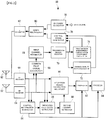
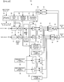
- Figure 1 is a diagram illustrating a configuration of a base station device 10 according to the present embodiment
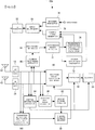
- Figure 2 is a diagram illustrating a configuration of a terminal device 60 according to the present embodiment
- Figure 3 is a diagram illustrating a configuration of a wireless communication system comprising the base station device 10 and the terminal device 60.
- the wireless communication system comprises a base station device 10 and a plurality of terminal devices 60.
- an mth terminal device among the plurality of terminal devices 60 will be denoted by adding a hyphenated character such as terminal device 60-m.
- the base station device 10 and the terminal device 60 respectively have two antennas 26, the number of antennas is not limited to two.
- the following description will be given on the premise that the base station device 10 has Nt number of antennas and the terminal device 60 has Ns number of antennas.
- configurations of the base station device 10 and the terminal device 60 will be described.
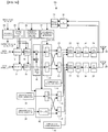
- FIG. 1 is a diagram illustrating a configuration of the base station device 10.
- the base station device 10 comprises: a plurality of encoders 12 that encodes a data signal to be transmitted to respective terminal devices 60; a plurality of modulators 14 that modulate the encoded data signal; an interference canceller 16 that cancels interference from the modulated signal; a first transmission weight multiplier 18 that multiplies the interference-cancelled modulated signal by a transmission weight; an adder 20 that adds the interference-cancelled modulated signal; a signal multiplexer 22 that multiplexes a common pilot signal and a dedicated pilot signal onto the added modulated signal; an RF transmitter 24 that converts the multiplexed signal into a wireless signal; and the plurality of antennas 26 that transmits the wireless signal.
- the RF transmitter 24 and the antennas 26 which function to transmit a signal generated by the signal multiplexer 22 correspond to the control signal transmitter and the data transmitter described in the claims.
- a channel quality data extractor 28 is connected to the encoder 12 and the modulator 14.
- the channel quality data extractor 28 extracts channel quality data from a reception signal received from the terminal device 60 via an RF receiver 36 and a demodulator/decoder 34.
- the channel quality data extractor 28 extracts channel quality data from signals received from the respective terminal devices 60. Therefore, the channel quality data has a different value for each terminal device 60.
- channel quality data of a terminal device 60-m will be denoted as channel quality data Q (m) .
- values thereof will be denoted in the same manner by adding a superscript of (m) and the like.
- the channel quality data extractor 28 notifies the channel quality data Q (m) to the encoder 12 and the modulator 14. Based on the channel quality data Q (m) , the encoder 12 and the modulator 14 encode and modulate transmission data to be transmitted to the terminal device 60-m.
- a transmission interference cancellation coefficient extractor 30 is connected to the interference canceller 16.
- the transmission interference cancellation coefficient extractor 30 extracts transmission interference cancellation coefficient data ⁇ (k - L) (m) from a reception signal received from the terminal device 60-m via the RF receiver 36 and the demodulator/decoder 34, where k represents a discrete time and (k - L) represents a period in which a transmission weight or an interference cancellation coefficient had been measured by the terminal device 60-m.
- a transmission weighting data extractor 32 is connected to the first transmission weight multiplier 18.
- the transmission weighting data extractor 32 extracts transmission weighting data V1(k - L) (m) and V2(k - L) (m) from a reception signal received from the terminal device 60-m.
- the transmission weighting data V1 and V2 is selected by a maximum SNR criterion and a minimum SNR criterion at the terminal device 60-m. Details on obtaining transmission weighting data V1 and V2 will be given in the description of the configuration of the terminal device 60.
- Interference cancellation coefficient data and transmission weighting data are obtained at time k based on a propagation path status before a discrete time L.
- a method can be used in which transmission weighting data is notified using a number (identifier) stored in a transmission weight table shared between the base station device 10 and the terminal device 60. Accordingly, since transmission weighting data only requires information on a transmission weight number, the amount of information when notifying a transmission weight can be reduced.
- a method can be used in which an appropriately quantized reception quality table is shared between the base station device 10 and the terminal device 60 and channel quality data is notified using a number stored in the channel quality table (reception quality table).
- a reception quality table and a transmission weight table are stored in the transmission interference cancellation coefficient extractor 30 and the transmission weighting data extractor 32 of the base station device 10.
- the reception quality table and the transmission weight table are stored in a transmission interference cancellation coefficient calculator 74, a transmission weight selector 70, and a channel quality data calculator 72 of the terminal device 60.
- the amount of information can be reduced down to just a predetermined number of quantization bits and the amount of feedback from the terminal device 60 to the base station device 10 can be reduced.
- a multilevel modulation/encoding ratio table that associates numbers of multilevel modulation and encoding ratios based on a measured channel quality can be shared by the base station device 10 and the terminal device 60, whereby reception quality data is to be notified using a number stored in the multilevel modulation/encoding ratio table. Accordingly, the amount of information when notifying channel quality can be reduced.
- the multilevel modulation/encoding ratio table is stored in the channel quality data extractor 28 of the base station device 10 and the channel quality data calculator 72 of the terminal device 60.
- the interference canceller 16 Based on the transmission interference cancellation coefficient data ⁇ (k - L), the interference canceller 16 performs interference cancellation so as to reduce interference between terminal devices 60 to be spatially multiplexed.
- a data signal is transmitted.
- the first transmission weight multiplier 18 multiplies the data signal (including a user individual control signal) to be transmitted to the terminal device 60 by a transmission weight.
- the signal multiplexer 22 multiplexes a common pilot signal series y p (k), a dedicated pilot signal series y q (k), and the data signal series y g (k) using any of FDM, TDM, and CDM or a combination thereof to generate and output a pilot signal having a predetermined frame configuration.
- the pilot signal generated by multiplexing will now be described.
- Figure 4 illustrates an example of a frame configuration of a pilot signal to be transmitted from the base station.
- a common pilot signal and a dedicated pilot signal are multiplexed using TDM.
- the frame includes a common pilot signal section, a dedicated pilot signal section, and a data signal/control signal section.
- the common pilot signal is multiplexed for each of the plurality of antennas 26 and the dedicated pilot signal is multiplexed for each weight formed by a plurality of transmission weights.
- the terminal device 60 can separate and receive the pilot signals and perform channel estimation per antenna 26 or per weight.
- the base station device 10 comprises a common pilot signal generator 44 and a dedicated pilot signal generator 38 that generate a common pilot signal and a dedicated pilot signal to be multiplexed onto a data signal.
- the common pilot signal generator 44 generates a common pilot signal series p n (k), where n denotes a natural number equal to or smaller than the number of transmitting antennas Nt and k denotes a discrete time.
- the common pilot signal generator 44 inputs the generated common pilot signal to the signal multiplexer 22. In other words, the common pilot signal series p n (k) is not multiplied by a transmission weight.
- the dedicated pilot signal generator 38 inputs the generated dedicated pilot signal to the second transmission weight multiplier 40.
- a dedicated pilot signal series to be transmitted to an mlth terminal device 60-m1 will now be described.
- the second transmission weight multiplier 40 multiplies a dedicated pilot signal series q s (k) by a weight based on transmission weighting data (V1 (m1) , V2 (m1) ) and on transmission interference cancellation coefficient data ⁇ (k - L) (m1) , and outputs the dedicated pilot signal multiplied by weight.
- a signal is generated by multiplying an sth dedicated pilot signal series q s (k) by a transmission weight.
- the base station device 10 comprises a resource allocator 46.
- the resource allocator 46 determines a combination of terminal devices 60 to be spatially multiplexed based on transmission weighting data (V1 (m) , V2 (m) ) outputted from the transmission weighting data extractor 32 and on reception quality data Q (m) outputted from the channel quality data extractor 28, and allocates resources such as a frequency, a time, a sign, and the like.
- output signals from the channel quality data extractor 28, the transmission interference cancellation coefficient extractor 30, and the transmission weighting data extractor 32 are inputted to the resource allocator 46.
- the resource allocator 46 outputs a resource allocation signal including a combination of terminal devices 60 to be spatially multiplexed, a frequency, a time, a code, and the like to the encoder 12, the modulator 14, the interference canceller 16, the first transmission weight multiplier 18, the second transmission weight multiplier 40, and the signal multiplexer 22.
- output signals from the channel quality data extractor 28, the transmission interference cancellation coefficient extractor 30, and the transmission weighting data extractor 32 are inputted to the resource allocator 46.
- the resource allocator 46 outputs a resource allocation signal including a combination of terminal devices 60 to be spatially multiplexed, a frequency, a time, a sign, and the like to the encoder 12, the modulator 14, the interference canceller 16, the transmission weight multiplier 18, the signal multiplexer 22, and a transmission interference cancellation coefficient data/transmission weighting data generator 48.
- the resource allocator 46 notifies the terminal devices 60-m1 and 60-m2 that dedicated data transmission is to be performed. In doing so, control information including MCS data and transmission power data during data transmission is to be transmitted as a control signal.
- control information including MCS data and transmission power data during data transmission is to be transmitted as a control signal.
- dedicated data transmission is to be performed at a power equivalent to a transmission power during transmission of a dedicated pilot signal
- transmission power data of the dedicated data signal need not be included in control information.
- control information including transmission power data is to be transmitted from the base station device 10 to the terminal device 60.
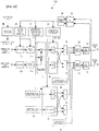
- Figure 2 is a diagram illustrating a configuration of the terminal device 60.
- the terminal device 60 comprises a common pilot signal extractor 66, a first channel estimator 68, a transmission weight selector 70, a channel quality data calculator 72, a transmission interference cancellation coefficient calculator 74, a control signal generator 76, an encoder/modulator 78, and a signal multiplexer 80.
- the terminal device 60 comprises a control information extractor 84, a dedicated pilot signal extractor 86, a second channel estimator 88, a reception weight calculator/multiplier 90, a demodulator 92, and a decoder 94.
- the common pilot signal extractor 66 receives a signal via an antenna 62 and an RF receiver 64, and extracts a common pilot signal from the reception signal.
- the first channel estimator 68 performs channel estimation based on a reception result of a common pilot signal y p (k) transmitted from the base station device 10.
- the total number of channel estimates of an mth terminal device 60-m can be expressed as (N t : the number of common pilot signal series) ⁇ (N s (m): the number of receiving antennas of terminal device 60-m).
- h m (j 2 , j 1 ) denotes a channel estimate when the terminal device 60-m receives a j 1 th common pilot signal series with a j 2 th antenna 62.
- the transmission weight selector 70 selects specific transmission weights (V1, V2) according to the following selection criteria from a fixed transmission weight group u n that is mutually known between the base station device 10 and the terminal device 60. In addition, the transmission weight selector 70 uses the selected transmission weight V1 to estimate a reception quality based on a maximum SNR in the event of transmitting a data signal. In addition, as an alternative method, a reception quality based on an SINR using a maximum SNR obtained by a maximum SNR criterion and a minimum SNR obtained by a minimum SNR criterion may be estimated. An SINR is calculated as, for example, (maximum SNR/minimum SNR).
- a transmission weight selection method will be given below.
- a maximum SNR criterion a fixed transmission weight V1 that provides a maximum SNR is selected using a channel estimate H(m).
- n denotes a natural number equal to or smaller than a maximum number of fixed transmission weight candidates.
- V2 u n
- a feedback of a transmission weight selection result from the terminal device 60 to the base station device 10 is performed by any of: (1) sending index data of a selection result of two kinds of transmission weights (V1, V2); (2) sending index data of a two-dimensional table (x, y) that combines two kinds of transmission weights; and (3) sending index data of a table restricted to a portion of combinations of a two-dimensional table that combines two kinds of transmission weights (for example, a table is used limited to combinations of weights by excluding weights adjacent to each other in a main weighting direction).
- search candidates of transmission weights to be selected by the minimum SNR criterion can be searched from a subset of limited transmission weight combinations, thereby enabling a reduction in computation quantity.
- the table is stored in the transmission weight selector 70.
- ⁇ m H m V 1 m H H m V 2 m ⁇ H m V 1 m ⁇ 2
- the interference cancellation coefficient can be calculated as a single complex number coefficient that does not depend on the number of transmitting antennas Nt of the base station device 10 and the number of receiving antennas Ns(m) of the terminal device 60-m. In other words, even when the number of transmitting antennas Nt and the number of receiving antennas Ns are large, the amount of information related to the interference cancellation coefficient to be notified to the base station device 10 remains the same. Therefore, a significant reduction effect on the amount of information related to the interference cancellation coefficient to be fed back to the base station device 10 can be obtained particularly when the number of transmitting antennas Nt or the number of receiving antennas Ns is large.
- the control signal generator 76 generates a control signal for feeding back interference cancellation coefficient data, channel reception quality data, and selected transmission weighting data to the base station device 10.
- the signal multiplexer 80 multiplexes an output signal from the encoder/modulator 78 that is an encoded and modulated data signal with an output signal from the control signal generator 76.
- Signal multiplexing is performed using any of FDM, TDM, CDM or a multiplexing method that is a combination thereof.
- the control information extractor 84 extracts control information including resource allocation data, dedicated pilot signal series data, channel quality data when performing data transmission (MCS data), and power transmission data from the control signal transmitted from the base station device 10.
- the dedicated pilot signal series data includes information on a dedicated pilot signal series by which a desired data signal is to be transmitted. In other words, information is included which indicates which of the transmission weights V1 or V2 is being used for transmission.
- the dedicated pilot signal extractor 86 extracts a dedicated pilot signal from a signal received via the RF receiver 64.
- the second channel estimator 88 performs channel estimation based on a reception result of a dedicated pilot signal y q (k) transmitted from the base station device 10.
- a channel estimation result (hereinafter referred to as a "channel estimate") obtained here can be expressed as a matrix Z(m).
- Z(m) will be referred to as a second channel estimation matrix.
- the total number of channel estimates at the terminal device 60-m can be expressed as (Nb: the number of dedicated pilot signal series transmitted from the base station) ⁇ (N s (m) : the number of receiving antennas of terminal device 60-m).
- Nb the number of dedicated pilot signal series transmitted from the base station
- N s (m) the number of receiving antennas of terminal device 60-m.
- z m (j, s) denotes a channel estimate when the terminal device 60 receives an sth dedicated pilot signal series with a jth antenna 62.
- the reception weight calculator/multiplier 90 uses the second channel estimation matrix estimated by the second channel estimator 88 to calculate a reception weight and multiplies an output signal from the RF receiver 64 by the reception weight.
- a reception weight is calculated based on a ZF criterion, an MMSE criterion, or the like.
- a ZF criterion an inverse matrix Z -1 (m) of the second channel estimation matrix Z(m) is calculated, and when a desired data signal is to be transmitted by a transmission signal of Vs according to dedicated pilot signal series data, a row vector comprising an sth row of the inverse matrix Z -1 (m) is to be used as a reception weight. Accordingly, even when an error is included in the channel estimate H(m), an interference signal to a terminal device 60 to be spatially multiplexed can be cancelled.
- the demodulator 92 and the decoder 94 perform a demodulating operation and a decoding operation on an output of the reception weight calculator/multiplier 90.
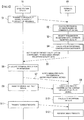
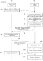
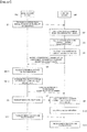
- FIG. 5 is a flow chart illustrating operations of a wireless communication system according to the present embodiment. Hereinafter, operations of the wireless communication system will be described with reference to Figure 5 .
- An nth common pilot signal generator 44 of the base station device 10 generates a common pilot signal series p n (k) and transmits the generated common pilot signal to the terminal device 60 (step S1).
- the terminal device 60 Upon receiving the common pilot signal transmitted from the base station device 10, the terminal device 60 performs channel estimation based on a reception result of a common pilot signal y p (k) and obtains a channel estimate (step S2).
- the transmission weight selector 70 of the terminal device 60 selects specific transmission weights (VI, V2) according to the selection criteria described above from a fixed transmission weight group u n that is mutually known between the base station device 10 and the terminal device 60, and further estimates a reception quality based on a maximum SNR in the event that a data signal is transmitted using the selected transmission weight V1 (step S3).
- the transmission interference cancellation coefficient calculator 74 of the terminal device 60-m calculates an interference cancellation coefficient ⁇ (m) (step S4).
- the interference cancellation coefficient ⁇ (m) assumes that: transmission is performed using the transmission weight V2 to another terminal device 60 to be spatially multiplexed; transmission is performed using the transmission weight V1 to a terminal device 60 of the same base station; and reception is performed at the receiving side using a maximum ratio combining weight.
- the control signal generator 76 of the terminal device 60 generates a control signal for feeding back interference cancellation coefficient data, channel reception quality data, and selected transmission weighting data to the base station device 10, and notifies the generated control signal to the base station device 10 (step S5).
- the base station device 10 uses the resource allocator 46 to determine a combination of terminal devices 60 to be spatially multiplexed based on transmission weighting data (V1 (m) , V2 (m) ) and reception quality data Q (m) transmitted from the plurality of terminal devices 60, and allocates resources such as a frequency, a time, a sign, and the like (step S6). After terminal devices 60 to be spatially multiplexed are determined, the base station device 10 notifies the terminal devices 60 that dedicated data transmission is to be performed (step S7). Additionally, in doing so, the base station device 10 transmits control information including MCS data and transmission power data during data transmission as a control signal.
- the terminal device 60 uses the control information extractor 84 to extract control information including resource allocation data, dedicated pilot signal series data, channel quality data when performing data transmission (MCS data), and power transmission data from the control signal transmitted from the base station device 10 (step S7).
- control information including resource allocation data, dedicated pilot signal series data, channel quality data when performing data transmission (MCS data), and power transmission data from the control signal transmitted from the base station device 10 (step S7).
- the base station device 10 transmits a dedicated pilot signal to the terminal device 60 (step S8).
- the dedicated pilot signal transmitted at this point is a signal obtained by multiplying a dedicated pilot signal series q s (k) by a weight based on transmission weighting data (V1 (m1) , V2 (m1) ) and on transmission interference cancellation coefficient data ⁇ (k - L) (m1) .
- the terminal device 60 Upon receiving a dedicated pilot signal, the terminal device 60 uses the second channel estimator 88 to perform channel estimation based on a reception result of the dedicated pilot signal y q (k) and calculates a channel estimate (step S9).
- the reception weight calculator/multiplier 90 of the terminal device 60 uses the second channel estimation matrix estimated by the second channel estimator 88 to calculate a reception weight (step S10), and multiplies an output signal from the RF receiver 64 by the reception weight.
- the base station device 10 processes a data signal to be transmitted to the terminal device 60 with the encoder 12, the modulator 14, the interference canceller 16, and the first transmission weight multiplier 18, and transmits the processed dedicated data to the terminal device 60 (step S11).
- the terminal device 60 uses the demodulator 92 and the decoder 94 to perform a demodulating operation and a decoding operation on an output of the reception weight calculator/multiplier 90 (step S12). This concludes the description on configurations and operations of the base station device 10 and the terminal device 60 according to the present embodiment.
- a result of a channel estimation matrix obtained by the first channel estimator 68 and a data signal d 1 (k) to be transmitted to the terminal device 60 may be given by the following expression (9).
- the superscript H denotes a complex conjugate operator.
- the data signal d s (k) to be transmitted to the terminal device 60 can be received without being affected by a same-channel interference signal from another terminal device 60 to be spatially multiplexed.
- the amount of transmission interference cancellation data ⁇ to be transmitted to the base station device 10 as feedback information from the terminal device 60 and overhead during data transmission can be reduced and data transmission efficiency can be increased.
- an interference signal from another user can be suppressed from the side of the terminal device 60 and reception property degradation can be suppressed. Consequently, same-channel interference waves from users to be spatially multiplexed can be reduced from the transmitting side and the transmission efficiency during spatial multiplexing transmission to a plurality of terminal devices 60 can be enhanced. As a result, frequency utilization efficiency can be improved.
- the wireless communication system may perform scheduling such that a terminal device existing on a cell edge, a terminal device with a large distance decay, and a terminal device with low reception quality are preferentially allocated as the terminal device 60 to which a data signal is to be transmitted using a transmission weight V1.
- a terminal device 60 existing on a cell edge is subjected to significant intercell interference.
- a degree of freedom of the antenna 62 can be used to suppress interference from other cells due to a DPC effect (an effect of cancelling same-channel interference of terminal devices 60 to be spatially multiplexed from the transmitting side). Accordingly, in addition to a spatial multiplexing effect, suppression of interference from other cells is enabled and cell edge throughput can be improved.
- a status of the amount of channel fluctuations of the terminal device 60 can be realized by performing feedback from the terminal device 60 to the base station device 10.
- a reduction in a reception quality improvement effect attributable to channel estimation errors can be prevented.
- scheduling is performed such that a terminal device 60 in the vicinity of the base station device 10, a terminal device 60 with high reception SNR, or the like is preferentially allocated as the terminal device 60 to which a data signal is to be transmitted using a transmission weight V1.
- a dedicated data signal to the terminal device 60-m1 and a different terminal device 60-m2 are transmitted by spatial multiplexing.
- a dedicated data signal to a relay device instead of the terminal device 60 and a dedicated data signal to another terminal device 60 can be transmitted by spatial multiplexing.
- a dedicated data signal to the terminal device 60 and a dedicated data signal to the same terminal device 60 can be spatially-multiplexed as a so-called single user MIMO.
- a configuration has been described in which the terminal device 60 selects a transmission weight from a plurality of weight candidates fixed in advance and the selected weight is notified to the base station device 10.
- an adaptive transmission weight using a QR decomposition as described in conventional examples may be used. In this case, notifying a channel estimate of a propagation path in advance to the base station device 10 or having the terminal device 60 feed back information related to a transmission weight adaptively generated based on a result of a first channel estimate shall suffice.
- interference cancellation operations by the interference canceller based on the interference cancellation coefficient ⁇ is not limited thereto.
- a similar effect can be achieved by alternatively using a Tomlinson-Harashima precoding method disclosed in " New automatic equalizer employing modulo arithmetic" (M. Tomlinson (March 1971). Electron. Lett. 7: 138-139 ), “ Matched-transmission technique for channels with intersymbol interference” (H. Harashima and H. Miyakawa (March 1972). IEEE Trans. Commun.
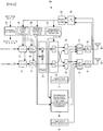
- Figure 6 is a diagram illustrating a configuration of a base station device 10a according to a second embodiment
- Figure 7 is a diagram illustrating a configuration of a terminal device 60a according to the second embodiment.
- a wireless communication system according to the second embodiment will be described with reference to Figures 6 and 7 .
- a transmission interference cancellation coefficient data/transmission weighting data generator 48 is provided in place of the dedicated pilot signal generator 38 and the second transmission weight multiplier 40.
- the transmission interference cancellation coefficient data/transmission weighting data generator 48 generates a control signal series for notifying transmission weighting data (V1 (m1) , V2 (m1) and transmission interference cancellation coefficient data ⁇ (k - L) (m1) to an mlth terminal device 60a-m1.
- the transmission interference cancellation coefficient data/transmission weighting data generator 48 inputs the generated control signal series to a signal multiplexer 22.
- the signal multiplexer 22 multiplexes a common pilot signal series y p (k), the control signal series, and a data signal series y g (k) using any of FDM, TDM, and CDM or a combination thereof to generate and output a signal having a predetermined frame configuration.
- Figure 8 illustrates an example of a frame configuration of a pilot signal to be transmitted from a base station when common and dedicated pilot signals are multiplexed using TDM.
- the frame includes a common pilot signal section, a control signal section, and a data signal/control signal section.
- the common pilot signal is multiplexed using any of FDM, TDM, and CDM or a combination thereof for each of a plurality of antennas.
- the terminal device 60a separates and receives the common pilot signals and performs channel estimation per antenna or per weight.
- a portion of the control signal section is transmitted without weighting by a transmission weight. Accordingly, the control signal can be demodulated using a channel estimate obtained from the common pilot signal.
- the terminal device 60a according to the second embodiment will be described. As illustrated in Figure 7 , while the basic configuration of the terminal device 60a according to the second embodiment is the same as the basic configuration of the terminal device 60 according to the first embodiment, a transmission interference cancellation coefficient data/transmission weighting data extractor 96 and a channel estimate modifier 98 are provided in place of the dedicated pilot signal extractor 86 and the second channel estimator 88.
- the transmission interference cancellation coefficient data/transmission weighting data extractor 96 extracts the transmission interference cancellation coefficient data ⁇ (k - L) (m1) and the transmission weighting data (V1 (m1) , V2 (m1) ) transmitted from the base station device 10a.
- the channel estimate modifier 98 calculates a second channel estimate Z(m s ) that is a channel estimate modified based on data from the transmission interference cancellation coefficient data/transmission weighting data extractor 96.
- Figure 9 is a flow chart illustrating operations of the wireless communication system according to the second embodiment. While basic operations of the wireless communication system according to the second embodiment is the same as the basic operations of the wireless communication system according to the first embodiment, a difference is that after terminal devices 60a to be spatially multiplexed are determined by a resource allocator 46, a process is performed for notifying the terminal devices 60a that dedicated data transmission is to be performed (step S70).
- the wireless communication system is capable of transmitting transmission interference cancellation coefficient data and transmission weighting data as a control signal to terminal devices 60a to be spatially multiplexed and notifying information related to a propagation channel that fluctuates when interference cancellation and transmission weight multiplication are performed in advance at a base station device to other terminal devices 60a to be spatially multiplexed. Therefore, the same advantageous effects as the first embodiment can be achieved.
- the terminal device 60a according to the second embodiment no longer requires a second channel estimator, there is an advantage that the terminal device 60a can be configured in a simpler manner.
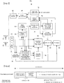
- Figure 10 is a diagram illustrating a configuration of a base station device 10b according to a third embodiment
- Figure 11 is a diagram illustrating a configuration of a terminal device 60b according to the third embodiment.
- a wireless communication system according to the third embodiment will be described with reference to Figures 10 and 11 .
- the base station device 10b according to the third embodiment includes a transmission interference cancellation coefficient data generator 50 in addition to the configuration of the base station device 10 according to the first embodiment.
- the transmission interference cancellation coefficient data generator 50 generates a control signal series for notifying transmission interference cancellation coefficient data ⁇ (k - L) (m1) .
- the transmission interference cancellation coefficient data generator 50 inputs the generated control signal series to a signal multiplexer 22.
- the signal multiplexer 22 multiplexes a common pilot signal series y p (k), a dedicated pilot signal series, the control signal series, and a data signal series y g (k) using any of FDM, TDM, and CDM or a combination thereof to generate and output a signal having a predetermined frame configuration.
- output signals from a channel quality data extractor 28, a transmission interference cancellation coefficient extractor 30, and a transmission weighting data extractor 32 are inputted to a resource allocator 46.
- the resource allocator 46 outputs a resource allocation signal including a combination of terminal devices 60 to be spatially multiplexed, a frequency, a time, a code, and the like to an encoder 12, a modulator 14, an interference canceller 16, a first transmission weight multiplier 18, a second transmission weight multiplier 40, the signal multiplexer 22, and the transmission interference cancellation coefficient data generator 50.
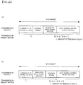
- Figure 12A illustrates an example of a frame configuration of a pilot signal to be transmitted from the base station device 10b.
- a common pilot signal and a dedicated pilot signal are multiplexed using TDM.
- a frame of the pilot signal includes a common pilot signal section, a dedicated pilot signal section, a control signal section, and a data signal/control signal section.
- the common pilot signal is multiplexed using any of FDM, TDM, and CDM or a combination thereof for each of a plurality of antennas.
- the control signal section is not multiplied by a transmission weight. Accordingly, the terminal device 60b is now capable of demodulating the control signal using a channel estimate obtained from the common pilot signal.
- a configuration of a frame that multiplexes a common pilot signal and a dedicated pilot signal is not limited to the example illustrated in Figure 12A .
- the control signal section can be multiplied by the same transmission weight used for the dedicated pilot signal. Accordingly, the terminal device 60b is now capable of demodulating the control signal using a channel estimate obtained from the dedicated pilot signal. Since the example illustrated in Figure 12B transmits a dedicated pilot signal using a transmission weight that improves reception quality, channel estimation accuracy can be improved.
- the terminal device 60b according to the third embodiment includes a transmission interference cancellation coefficient data extractor 100 in place of the transmission interference cancellation coefficient data/transmission weighting data extractor 96.
- the transmission interference cancellation coefficient data extractor 100 functions to extract transmission interference cancellation coefficient data ⁇ (k - L) (m1) transmitted from the base station device 10b.
- Figure 13 is a flow chart illustrating operations of the wireless communication system according to the third embodiment. While basic operations of the wireless communication system according to the third embodiment is the same as the basic operations of the wireless communication system according to the first embodiment, a difference is that after terminal devices 60b to be spatially multiplexed are determined by the resource allocator 46, a notification is made to the terminal devices 60b that dedicated data transmission is to be performed (step S71).
- the transmission interference cancellation coefficient data generator 50 of the base station device 10b generates a control signal series of the transmission interference cancellation coefficient data ⁇ (k - L) (m1) with respect to a combination of terminal devices 60b to be spatially multiplexed as determined by the resource allocator 46, and inputs the generated control signal series to a signal multiplexer 22.
- the second transmission weight multiplier 40 of the base station device 10b inputs a dedicated pilot signal obtained by multiplying a dedicated pilot signal series q s (k) by a weight based on determined transmission weighting data (V1 (m1) , V2 (m1) ) as given by the expression below to the signal multiplexer 22.
- a signal is generated by multiplying an sth dedicated pilot signal series q s (k) by a transmission weight expressed below.
- the signal multiplexer 22 multiplexes a common pilot signal series y p (k), the dedicated pilot signal series y q (k), a control signal series, and a data signal series y g (k) using any of FDM, TDM, and CDM or a combination thereof to generate and output a signal having a predetermined frame configuration (step S8).
- the base station device 10b transmits only transmission interference cancellation coefficient data ⁇ as a control signal to a terminal device 60b to be spatially multiplexed. Accordingly, information related to a propagation channel that fluctuates when interference cancellation is performed in advance at the base station device 10b can be notified to other terminal devices 60b to be spatially multiplexed. Consequently, the amount of control information can be reduced in comparison to the wireless communication system according to the second embodiment.
- the base station device 10b since the base station device 10b transmits a dedicated pilot signal to the terminal device 60b using a transmission weight that improves reception quality, channel estimation accuracy can be improved.
- a wireless communication system according to a fourth embodiment will be described. While a basic configuration the wireless communication system according to the fourth embodiment is the same as the basic configuration of the wireless communication system according to the first embodiment, for the fourth embodiment, an example will be described in which the present invention is applied to multicarrier transmission such as OFDM or OFDMA.
- FIG 14 is a diagram illustrating a configuration of a base station device 10c according to the fourth embodiment.
- the base station device 10c according to the fourth embodiment comprises an FFT unit 52 and a CP adder 54 in addition to the configuration of the base station device 10 according to the first embodiment.
- the FFT unit 52 performs FFT processing on an inputted subcarrier signal fd.
- the CP adder 54 adds a cyclic prefix.
- output signals from a channel quality data extractor 28, a transmission interference cancellation coefficient extractor 30, and a transmission weighting data extractor 32 are inputted to a resource allocator 46.
- the resource allocator 46 outputs a resource allocation signal including a combination of terminal devices 60 to be spatially multiplexed, a frequency, a time, a code, and the like to an encoder 12, a modulator 14, an interference canceller 16, a first transmission weight multiplier 18, a second transmission weight multiplier 40, and a signal multiplexer 22.
- Figure 15 is a diagram illustrating a configuration of a terminal device 60c according to the fourth embodiment.
- the terminal device 60c according to the fourth embodiment comprises a cyclic prefix removal Unit 102 and an IFFT unit 104 in addition to the configuration of the terminal device 60 according to the first embodiment.
- the cyclic prefix removal Unit 102 and the IFFT unit 104 perform OFDM modulation.
- the configurations enable an inputted time domain signal to be converted to a frequency-domain subcarrier signal.
- An nth common pilot signal generator 44 of the base station device 10c generates a common pilot signal series p n (k, f d ) as given by the following expression, and transmits the generated common pilot signal.
- n denotes a natural number equal to or smaller than the number of transmitting antennas Nt and k denotes a discrete time.
- the common pilot signal series p n (k, f d ) is inputted to the signal multiplexer 22 without being multiplied by a transmission weight (step S1).
- y p k f d p 1 k f d ⁇ p Nt k f d
- the terminal device 60c having received the common pilot signal causes a first channel estimator 68 to perform channel estimation for each subcarrier based on reception results of the common pilot signal y p (k, f d ) transmitted from the base station device 10c (step S2).
- a channel estimation result (hereinafter referred to as a "channel estimate") obtained as described above can be expressed by the following matrix.
- the total number of channel estimates at an mth terminal device 60c-m can be expressed as (N t : number of common pilot signal series) ⁇ (N s (m): number of receiving antennas of terminal device 60c-m).
- h m (j 2 , j 1 , f d ) denotes a channel estimate when the terminal device 60c-m receives a j 1 th common pilot signal series with a j 2 th antenna with respect to an f d th subcarrier signal.
- a transmission weight selector 70 selects specific transmission weights (V1(f d ), V2(f d )) according to the selection criteria described below from a fixed transmission weight group u n that is mutually known between the base station device 10c and the terminal device 60c for each subcarrier f d , and further estimates a reception quality based on a maximum SNR in the event that a data signal is transmitted using the selected transmission weight V1(f d ) (step S3).
- a reception quality based on an SINR using a maximum SNR obtained by a maximum SNR criterion and a minimum SNR obtained by a minimum SNR criterion may be estimated.
- An SINR is calculated as, for example, (maximum SNR/minimum SNR).
- n denotes a natural number equal to or smaller than a maximum number of fixed transmission weight candidates.
- notification of a transmission weight selection result is performed by any of: (1) sending index data of a selection result of two kinds of transmission weights (V1(f d ), V2(f d )); (2) sending index data of a two-dimensional table (x, y) that combines two kinds of transmission weights; and (3) sending index data of a table restricted to a portion of combinations of a two-dimensional table that combines two kinds of transmission weights (for example, a table is used limited to combinations of weights by excluding weights adjacent to each other in a main weighting direction).
- search candidates of transmission weights to be selected by the minimum SNR criterion can be searched from a subset of limited transmission weight combinations, enabling a reduction in computation quantity.
- a transmission interference cancellation coefficient calculator 74 of the terminal device 60c calculates an interference cancellation coefficient ⁇ (m) (f d ) such as provided below for each subcarrier f d (step S4).
- the transmission interference cancellation coefficient calculator 74 transmits the interference cancellation coefficient ⁇ (m) (f d ) to: another terminal device 60c to be spatially multiplexed using the transmission weight V2(f d ); and to a terminal device 60c of the same base station using the transmission weight V1(f d ).
- an interference cancellation coefficient ⁇ (m) (f d ) is calculated on the assumption that reception is to be performed using a maximum ratio combining weight.
- the interference cancellation coefficient can be calculated as a single complex number coefficient that does not depend on the number of transmitting antennas Nt of the base station device 10c and the number of receiving antennas Ns(m) of the terminal device 60c. In other words, even when the number of transmitting antennas Nt and the number of receiving antennas Ns are large, the amount of information to be notified to the base station device 10c remains the same. Therefore, a significant reduction effect on the amount of information to be fed back to the base station device 10c can be obtained particularly when the number of transmitting antennas Nt or the number of receiving antennas Ns is large.
- a control signal generator 76 generates a control signal for feeding back interference cancellation coefficient data, channel reception quality data, and selected transmission weighting data for each subcarrier f d to the base station device 10c.
- a signal multiplexer 80 multiplexes an output signal from an encoder/modulator 78 that is an encoded and modulated data signal with an output signal from the control signal generator 76.
- the signal multiplexer 80 uses any of FDM, TDM, CDM or a multiplexing method that is a combination thereof.
- the terminal device 60c transmits a control signal generated through multiplexing to the base station device 10c (step S5).
- the base station device 10c Upon receiving the control signal transmitted from the terminal device 60c, the base station device 10c causes the transmission weighting data extractor 32 to extract transmission weighting data V1(k - L, f d ) (m) and V2(k - L, f d ) (m) transmitted from an mth terminal device 60c-m from the reception signal.
- the transmission weighting data V1 and V2 is transmission weights selected by a maximum SNR criterion and a minimum SNR criterion at the terminal device 60c-m, where m takes a natural number equal to or smaller than the number Nms of terminal devices existing within an area of the base station device.
- the channel quality data extractor 28 extracts channel quality data Q(m, f d ) transmitted from the terminal device 60c-m from the reception signal.
- the transmission interference cancellation coefficient extractor 30 extracts transmission interference cancellation coefficient data ⁇ (k - L, f d ) (m) transmitted from the terminal device 60c-m from the reception signal, where k represents a discrete time and (k -L) represents a period in which a transmission weight or an interference cancellation coefficient had been measured by the terminal device 60cm.
- transmission weighting data and interference cancellation coefficient data are obtained at time k based on a propagation path status before a discrete time L.
- the resource allocator 46 determines a combination of terminal devices to be spatially multiplexed based on transmission weighting data (V1 (m) (f d ), V2 (m) (f d )) and reception quality data Q(m, f d ) per subcarrier outputted from the plurality of terminal devices 60, and allocates resources such as a frequency, a time, a sign, and the like (step S6).
- a combination of terminal devices to be spatially multiplexed is determined such that with respect to a terminal device 60-ml, a transmission weight V2 (m1) selected by a minimum SNR criterion with respect to another terminal device 60-m2 to be simultaneously multiplexed becomes equal to a transmission weight V1 (m2) selected by a maximum SNR criterion.
- a transmission weight that maximizes SNR for each terminal device 60c-m1, 60c-m2 is set to (V1 (m1) (f d ), V1 (m2) (f d )) to be used for transmitting a data signal.
- the transmission weight equals a combination (V1 (m1) (f d ), V2 (m1) (f d )) of transmission weights that maximizes SINR.
- step S7 After terminal devices 60c to be spatially multiplexed with respect to a subcarrier has been determined by the resource allocator 46, a notification that dedicated data transmission is to be performed together with information on the subcarrier to be used is made to the terminal devices 60c (step S7). In doing so, control information including MCS data and transmission power data during data transmission is to be transmitted as a control signal (step S7). Moreover, when transmission power during data transmission in spatial multiplex transmission is equal to transmission power during transmission of a dedicated pilot signal, transmission power data on the dedicated data signal need not be included in control information. In addition, as an alternative method, when sending a dedicated data signal at a different transmission power than the dedicated pilot signal, control information including transmission power data is to be transmitted from the base station device 10c to the terminal device 60c.
- the terminal device 60c Upon receiving a control signal for dedicated data transmission notification transmitted from the base station device 10c, the terminal device 60c causes the control information extractor 84 to extract control information including resource allocation data, dedicated pilot signal series data, channel quality data for each subcarrier when performing data transmission (MCS data), and power transmission data from the control signal.
- dedicated pilot signal series data includes information on a dedicated pilot signal series by which a desired data signal is to be transmitted. In other words, information is included indicating which of the transmission weights V1 or V2 is used for transmission.
- the second transmission weight multiplier 40 of the base station device 10c outputs a dedicated pilot signal obtained as given by expression (19) below by multiplying a dedicated pilot signal series q s (k, f d ) by a weight based on transmission weighting data (V1 (m1) (f d ), V2 (m1) (f d )) and transmission interference cancellation coefficient data ⁇ (k -L, f d ) (m1) determined for each subcarrier f d (step S8).
- y q denotes a column vector including an Nt-dimensional element.
- a second channel estimator 88 performs channel estimation for each subcarrier based on a reception result of a dedicated pilot signal y q (k, f d ) transmitted from the base station device 10c (step S9).
- the channel estimation result obtained at this point may be expressed using a matrix Z(m, f d ) as given by expression (20) below (hereinafter, this matrix shall be referred to as a "second channel estimation matrix).
- the total number of channel estimates of an f d th subcarrier signal at an mth terminal device 60c-m can be expressed as (Nb: number of dedicated pilot signal series transmitted from base station) ⁇ (N s (m): number of receiving antennas of terminal device 60c-m).
- Nb number of dedicated pilot signal series transmitted from base station
- N s (m) number of receiving antennas of terminal device 60c-m.
- z m (j, s, f d ) denotes a channel estimate of the f d th subcarrier signal when the terminal device 60c-m receives an sth dedicated pilot signal series with a jth antenna.
- a reception weight calculator/multiplier 90 uses the second channel estimation matrix estimated by the second channel estimator 88 for each subcarrier to calculate a reception weight, and multiplies an output signal of the RF receiver 64 by the reception weight (step S10).
- a reception weight is calculated based on a ZF criterion, an MMSE criterion, or the like.
- an inverse matrix Z -1 (m, f d ) of the second channel estimation matrix Z(m, f d ) is calculated, and when a desired data signal is to be transmitted by a transmission signal of Vs according to dedicated pilot signal series data, a row vector comprising an sth row of the inverse matrix Z -1 (m, f d ) is to be used as a reception weight. Accordingly, even when an error is included in the channel estimate H(m, f d ), an interference signal to a terminal device to be spatially multiplexed can be cancelled.
- Each data signal to be transmitted to the terminal devices 60-m1 and 60-m2 is processed by the encoder 12, the modulator 14, the interference canceller 16, and the first transmission weight multiplier 18, and outputted to the signal multiplexer 22.
- the following process is performed at the interference canceller 16 and the first transmission weight multiplier 18 (step S11).
- the interference canceller Based on the transmission interference cancellation coefficient data ⁇ (k - L, f d ), the interference canceller performs interference cancellation so as to reduce interference between terminal devices to be spatially multiplexed.
- a data signal g s (k, f d ) is transmitted.
- the first transmission weight multiplier 18 multiplies the data signal (including a user-individual control signal) to be transmitted to the terminal devices 60c-m1 and 60c-m2 by a transmission weight.
- a signal y g (g, f d ) is generated by multiplying the signal series g s (k, f d ) outputted from the interference canceller 16 by a transmission weight, where s denotes a natural number equal to or lower than the number of users connected by spatial multiplexing.
- the signal multiplexer 22 multiplexes a common pilot signal series y p (k, f d ), a dedicated pilot signal series y q (k, f d ), and the data signal series y g (k, f d ) using any of FDM, TDM, and CDM or a combination thereof to generate and output a signal having a predetermined frame configuration.
- the FFT unit 52 and the CP adder 54 perform OFDM modulation.
- the FFT unit 52 performs FFT processing on an inputted subcarrier signal f d .
- the CP adder 54 adds a cyclic prefix.
- a demodulator 92 and a decoder 94 perform a demodulating operation and a decoding operation on an output of the reception weight calculator/multiplier 90 (step S12).
- a result of a channel estimation matrix H(m s , f d ) obtained by the first channel estimator 68 with respect to a subcarrier f d of the terminal device 60c-m s and a reception signal r s (k, f d ) when a propagation channel at the time of data signal transmission include error fluctuations may be given by the following expression (24).
- the data signal d s (k, f d ) to be transmitted to the terminal device 60c-m s can be received without being affected by a same-channel interference signal from another terminal device to be spatially multiplexed.
- the configuration according to the first embodiment can also be applied to multi-carrier transmission such as OFDM and OFDMA.
- multi-carrier transmission such as OFDM and OFDMA.
- the configurations according to the second and third embodiments can similarly be applied to multi-carrier transmission such as OFDM and OFDMA.
- multi-carrier transmission such as OFDM and OFDMA.
- the description of the first embodiment given above mainly focused on operations performed when respectively transmitting dedicated data signals to be unicasted to a plurality of different terminal devices using spatial multiplexing.
- a wireless communication system will be described in greater detail with respect to a case where the wireless communication system is applied to the spatial multiplexing of an MBS (multicast and broadcast service) data signal (hereinafter referred to as a multicast signal) that is multicasted or broadcasted to transmit the same data to a limited plurality of terminals and a dedicated data signal that is unicast-transmitted to a specific terminal device.
- MBS multicast and broadcast service
- Figure 16 is a diagram illustrating a configuration of a base station device 10d according to a fifth embodiment. Since the configuration of a terminal device 60 is the same as the first embodiment, a description thereof will be omitted.
- the base station device 10d comprises: an encoder 12a that encodes a dedicated data signal 1a to be transmitted to the terminal device 60; an encoder 12b that encodes a data signal 2b to be multicasted (or broadcasted); modulators 14a and 14b that modulate the respective encoded data signals; an interference canceller 16 that cancels, in advance, multicast data that becomes an interference component from the modulated signal when a dedicated data signal is received at the terminal device 60; a first transmission weight multiplier 18 that multiplies the interference-cancelled modulated signal by a transmission weight; an adder 20 that adds the interference-cancelled modulated signal; a signal multiplexer 22 that multiplexes a common pilot signal and a dedicated pilot signal onto the added modulated signal; an RF transmitter 24 that converts the multiplexed signal into a wireless signal; and a plurality of antennas 26 that transmits the wireless signal. Moreover, the RF transmitter 24 and the antennas 26 which function to transmit a signal generated by the signal multiplex.
- a channel quality data extractor 28 is connected to the encoder 12a and the modulator 14a.
- the channel quality data extractor 28 extracts channel quality data from a reception signal received from the terminal device 60 via an RF receiver 36 and a demodulator/decoder 34.
- the channel quality data extractor 28 extracts channel quality data from signals received from the respective terminal devices 60. Therefore, the channel quality data has a different value for each terminal device 60.
- channel quality data of the terminal device 60-s will be denoted as channel quality data Q (s) .
- values thereof will be denoted in the same manner by adding a superscript of (s) and the like.
- the channel quality data extractor 28 notifies the channel quality data Q (s) to the encoder 12a and the modulator 14a. Based on the channel quality data Q (s) , the encoder 12a and the modulator 14a encode and modulate transmission data 1a to be transmitted to the terminal device 60-s.
- the encoder 12b and the modulator 14b encode and modulate transmission data 1b to be multicasted (or broadcasted).
- a transmission interference cancellation coefficient extractor 30 is connected to the interference canceller 16.
- the transmission interference cancellation coefficient extractor 30 extracts transmission interference cancellation coefficient data ⁇ (k - L) (s) from a reception signal received from the terminal device 60-s via the RF receiver 36 and the demodulator/decoder 34, where k represents a discrete time and (k -L) represents a period in which a transmission weight or an interference cancellation coefficient had been measured by the terminal device 60-s.
- a transmission weighting data extractor 32 is connected to the first transmission weight multiplier 18.
- the transmission weighting data extractor 32 extracts transmission weighting data V1(k - L) (s) and V2(k - L) (s) from a reception signal received from the terminal device 60-s.
- the transmission weighting data V1 and V2 is selected by a maximum SNR criterion and a minimum SNR criterion at the terminal device 60-s.
- interference cancellation coefficient data and transmission weighting data are obtained at time k based on a propagation path status before a discrete time L.
- the interference canceller 16 Based on the transmission interference cancellation coefficient data ⁇ (k - L) from the specific terminal device 60 to which dedicated data is to be transmitted, the interference canceller 16 performs interference cancellation so as to reduce interference of a multicast (or broadcast) data signal to be spatially multiplexed with the transmission of the dedicated data to the terminal device 60-s.
- the first transmission weight multiplier 18 multiplies a signal series g s (k) outputted from the interference canceller 16 by a transmission weight as given by expression (2) to generate a signal y g (g).
- the present embodiment represents a case where the number of spatial multiplexing is 2.
- V1, V2, and y g in expression (2) represent column vectors including Nt-dimensional elements, where Nt denotes the number of transmitting antennas.
- the signal multiplexer 22 multiplexes a common pilot signal series y p (k), a dedicated pilot signal series y q (k), and a data signal series y g (k) using any of FDM, TDM, and CDM or a combination thereof to generate and output a pilot signal having a predetermined frame configuration.
- the base station device 10d comprises a common pilot signal generator 44 and a dedicated pilot signal generator 38 that generate a common pilot signal and a dedicated pilot signal to be multiplexed onto a data signal.
- the common pilot signal generator 44 generates a common pilot signal series p n (k), where n denotes a natural number equal to or smaller than the number of transmitting antennas Nt and k denotes a discrete time.
- the common pilot signal generator 44 inputs the generated common pilot signal to the signal multiplexer 22. In other words, the common pilot signal series p n (k) is not multiplied by a transmission weight.
- the dedicated pilot signal generator 38 inputs the generated dedicated pilot signal to the second transmission weight multiplier 40.
- a dedicated pilot signal series to be transmitted to the first terminal device 60-1 will now be described.
- the second transmission weight multiplier 40 multiplies a dedicated pilot signal series q s (k) by a weight based on transmission weighting data (V1, V2) and transmission interference cancellation coefficient data ⁇ (k - L) transmitted from the first terminal device 60-1, and outputs the dedicated pilot signal multiplied by weight.
- a signal is generated by multiplying an sth dedicated pilot signal series q s (k) by a transmission weight.
- the base station device 10d comprises a resource allocator 46.
- the resource allocator 46 determines a terminal device 60 to which dedicated data is to be transmitted based on transmission weighting data (V1 (m) , V2 (m) ) to be outputted from the transmission weighting data extractor 32 and on reception quality data Q (m) to be outputted from the channel quality data extractor 28 as transmitted from the plurality of terminal devices 60-m, and allocates resources such as a frequency, a time, a sign, and the like.
- the resource allocator 46 When a multicast (or broadcast) signal is transmitted together with a dedicated data signal to the terminal device 60-m by spatial multiplexing transmission, first, the resource allocator 46 first allocates resources such as a frequency, a time, and the like of a single terminal device 60-1 to which a dedicated data signal is to be transmitted by unicast based on reception quality data Q (m) outputted from the channel quality data extractor 28.
- transmission weighting data (V1, V2) transmitted from the resource-allocated terminal device 60-1 and outputted from the transmission weighting data extractor 32 is extracted and inputted to the first transmission weight multiplier 18.
- the dedicated data signal 1a to be unicasted to the resource-allocated terminal device 60-1 is inputted to the encoder 12a illustrated in Figure 16 .
- the data signal 1b to be broadcasted or multicasted that is simultaneously multiplexed at this point is inputted to the encoder 12b.
- the resource allocator 46 notifies the terminal device 60-1 that dedicated data transmission is to be performed.
- a notification is also made that a multicast (or broadcast) transmission is to be simultaneously performed.
- control information including MCS data and transmission power data during data transmission is to be transmitted as a control signal.
- dedicated data transmission is to be performed at a power equivalent to a transmission power during transmission of a dedicated pilot signal
- transmission power data of the dedicated data signal need not be included in control information.
- control information including transmission power data is to be transmitted from the base station device 10d to the terminal device 60.
- the configuration of the terminal device 60 is the same as the configuration according to the first embodiment described with reference to Figure 2 , a description thereof will be omitted.
- FIG 17 is a flow chart illustrating operations of a wireless communication system according to the present embodiment. Hereinafter, operations of the wireless communication system will be described with reference to Figure 17 .
- An nth common pilot signal generator 44 of the base station device 10d generates a common pilot signal series p n (k) and transmits the generated common pilot signal to the terminal device 60 (step S1).
- the terminal device 60 Upon receiving the common pilot signal transmitted from the base station device 10d, the terminal device 60 performs channel estimation based on a reception result of a common pilot signal y p (k) and calculates a channel estimate (step S2).
- the transmission weight selector 70 of the terminal device 60 selects specific transmission weights (V1, V2) according to the selection criteria described earlier from a fixed transmission weight group u n that is mutually known between the base station device 10d and the terminal device 60, and further estimates a reception quality based on a maximum SNR in the event that a data signal is transmitted using the selected transmission weight V1 (step S3).
- the transmission interference cancellation coefficient calculator 74 of the terminal device 60-m calculates an interference cancellation coefficient ⁇ (m) (step S4).
- the interference cancellation coefficient ⁇ (m) assumes that: transmission is performed using the transmission weight V2 to another terminal device 60 to be spatially multiplexed; transmission is performed using the transmission weight V1 to a terminal device 60 of the same base station; and reception is performed at the receiving side using a maximum ratio combining weight.
- the control signal generator 76 of the terminal device 60 generates a control signal for feeding back interference cancellation coefficient data, channel reception quality data, and selected transmission weighting data to the base station device 10d, and notifies the generated control signal to the base station device 10d (step S5).
- the base station device 10d uses the resource allocator 46 to determine a terminal device 60 to which dedicated data transmission is to be performed based on transmission weighting data (V1 (m) , V2 (m) ) and reception quality data Q (m) transmitted from the plurality of terminal devices 60, and allocates resources such as a frequency, a time, a sign, and the like (step S6-1). Subsequently, a transmission format such as a code, a modulation, and the like is determined in regards to a data signal to be multicast (or broadcast) and spatially multiplexed with the terminal device 60 to which dedicated data is to be transmitted (step S6-2).
- the base station device 10d After a unicast and a multicast (or a broadcast) signal to the terminal device 60 to be spatially multiplexed is determined, the base station device 10d notifies the terminal device 60 to which dedicated data transmission is to be performed and the terminal device 60 that is a target of the multicast (or a broadcast) that data transmission is to be performed (step S7). Additionally, in doing so, control information including MCS (Modulation and coding scheme) data and transmission power data during data transmission is to be transmitted as a control signal.
- MCS Modulation and coding scheme
- the terminal device 60 uses the control information extractor 84 to extract control information including resource allocation data, dedicated pilot signal series data, channel quality data when performing data transmission (MCS data), and power transmission data from the control signal transmitted from the base station device 10d (step S7).
- control information including resource allocation data, dedicated pilot signal series data, channel quality data when performing data transmission (MCS data), and power transmission data from the control signal transmitted from the base station device 10d (step S7).
- the base station device 10d After notification of dedicated data transmission and multicast (or broadcast), the base station device 10d transmits a dedicated pilot signal to the terminal device 60 (step S8).
- the dedicated pilot signal transmitted at this point is a signal obtained by multiplying a dedicated pilot signal series q s (k) by a weight based on transmission weighting data (V1 (m1) , V2 (m1) ) and on transmission interference cancellation coefficient data ⁇ (k - L) (m1) .
- the terminal device 60 Upon receiving a dedicated pilot signal, the terminal device 60 uses the second channel estimator 88 to perform channel estimation based on a reception result of the dedicated pilot signal y q (k) and calculates a channel estimate (step S9).
- the reception weight calculator/multiplier 90 of the terminal device 60 uses the second channel estimation matrix estimated by the second channel estimator 88 to calculate a reception weight (step S10), and multiplies an output signal from the RF receiver 64 by the reception weight.
- the base station device 10d processes the data signal 1a and the multicast (or broadcast) data signal 1b to be transmitted to the terminal device 60 with the encoders 12a and 12b, the modulators 14a and 14b, the interference canceller 16, and the first transmission weight multiplier 18, and transmits the processed dedicated data to the terminal device 60 (step S11).
- the terminal device 60 uses the demodulator 92 and the decoder 94 to perform a demodulating operation and a decoding operation on an output of the reception weight calculator/multiplier 90 (step S12). This concludes the description on configurations and operations of the base station device 10d and the terminal device 60 according to the present embodiment.
- the terminal device 60-1 to which dedicated data is to be transmitted can perform reception without being affected by a same-channel interference signal due to a multicast (or broadcast) signal to be spatially multiplexed.
- reception can be performed without being affected by a same-channel interference signal due to a multicast (or broadcast) signal to be spatially multiplexed by calculating a reception weight using when a result of a channel estimation matrix H(m s ) obtained by the first channel estimator 68 of the terminal device 60-m s and a channel estimate Z(m s ) obtained by the second channel estimator 88 when a propagation channel at the time of data transmission include error fluctuations.
- terminal devices 60 other than the terminal device 60-1 are now capable of receiving a multicast (or broadcast) signal to be transmitted by spatial multiplexing while suppressing degradation of reception quality at the terminal device 60 with respect to a dedicated data signal to be unicast-transmitted to the terminal device 60, frequency utilization efficiency can be further enhanced.
- the resource allocator 46 allocates a terminal device 60-s and transmits a dedicated data signal 1a-k so that the transmission weight V2 when transmitting a multicast (or broadcast) signal differs for each repetition transmission.
- Figure 18 illustrates transmission weights to be respectively used for a kth multicast (or broadcast) data signal 2b-k to be repetitively transmitted (repetition transmission) and the dedicated data signal 1a-k to be transmitted together with the data signal 2b-k by spatial multiplexing when a resource Rk that differs on a temporal axis or a frequential axis is allocated.
- the resource allocator 46 allocates a terminal device 60 such that the transmission weight V2(k)differs for each kth repetition transmission of the multicast (or broadcast) signal. Accordingly, an averaging effect of localized reception quality of the terminal device 60 within the area can be achieved.
- transmission power control may be added when transmitting a dedicated data signal.
- a multicast (or broadcast) signal may be arranged so as to be transmitted by spatial multiplexing only when transmission power is lower than a predetermined value as a result of transmission power control on a dedicated data signal.
- an effect may be achieved in that multicast (or broadcast) reception quality can also be ensured for terminal devices positioned in the vicinity of cell edges.
- the present invention has a beneficial effect in that reception property degradation attributable to performing interference cancellation in advance on a modulation signal to be transmitted can now be suppressed by a base station device. Consequently, a base station device according to the present invention is useful as a base station or the like that performs for example, space division multiple access.
Claims (8)
- Dispositif de station de base qui est capable de communiquer avec un premier dispositif terminal et un second dispositif terminal sur le même canal par multiplexage spatial, le dispositif de station de base comprenant :un extracteur de coefficient d'annulation d'interférence (30) adapté pour extraire un coefficient d'annulation d'interférence destiné à annuler une interférence sur un canal de propagation avec le second dispositif terminal à partir d'un signal reçu du premier dispositif terminal, le coefficient d'annulation d'interférence étant calculé en utilisant une pondération de transmission au niveau du premier dispositif terminal ; etle dispositif de station de base comprend en outreun extracteur de données de pondération de transmission (32) adapté pour extraire des informations concernant la pondération de transmission à partir du signal reçu du premier dispositif terminal ;un émetteur de signal de commande (24) adapté pour transmettre un signal de commande sur la base du coefficient d'annulation d'interférence et de la pondération de transmission aux dispositifs terminaux ;un dispositif d'annulation d'interférence (16) adapté pour générer des données de transmission (g1) à transmettre au premier dispositif terminal en utilisant le coefficient d'annulation d'interférence ;un multiplicateur de pondération (18) adapté pour multiplier des données de transmission (g1) respectives pour le premier dispositif terminal et des données de transmission (g2) pour le second dispositif terminal par la pondération de transmission ;un multiplexeur de signal (22) adapté pour multiplexer les données de transmission pour le premier dispositif terminal multipliées par la pondération de transmission et les données de transmission pour le second dispositif terminal multipliées par la pondération de transmission pour générer un signal multiplexé ; etun émetteur de données (24) adapté pour transmettre le signal multiplexé sur le même canal.
- Dispositif de station de base selon la revendication 1, comprenant en outre :un second multiplicateur de pondération (40) adapté pour générer un signal pilote en utilisant des informations concernant la pondération de transmission ; dans lequel le signal de commande comprend le signal pilote ; etle multiplexeur de signal (22) est adapté pour multiplexer les données de transmission pour le premier dispositif terminal multipliées par la pondération de transmission, les données de transmission pour le second dispositif terminal multipliées par la pondération de transmission, et le signal pilote pour générer un signal multiplexé.
- Dispositif de station de base selon la revendication 1, comprenant en outre :un générateur de signal de commande (48) adapté pour générer le signal de commande comprenant des informations concernant le coefficient d'annulation d'interférence et des informations concernant la pondération de transmission ; dans lequelle multiplexeur de signal (22) est adapté pour multiplexer les données de transmission pour le premier dispositif terminal multipliées par la pondération de transmission, les données de transmission pour le second dispositif terminal multipliées par la pondération de transmission et le signal de commande pour générer un signal multiplié.
- Dispositif de station de base selon la revendication 1, comprenant en outre :un générateur de signal de commande (48) adapté pour générer le signal de commande comprenant des informations concernant le coefficient d'annulation d'interférence et des informations concernant la pondération de transmission ; dans lequelle multiplexeur de signal (22) est adapté pour multiplexer les données de transmission pour le premier dispositif terminal multipliées par la pondération de transmission, les données de transmission pour le second dispositif terminal multipliées par la pondération de transmission et le signal de commande multiplié par la pondération de transmission pour générer un signal multiplié.
- Dispositif de station de base selon l'une quelconque des revendications 1 à 4, dans lequel
l'extracteur de coefficient d'annulation d'interférence (30) comprend une mémoire de coefficients d'annulation d'interférence qui stocke le coefficient d'annulation d'interférence en association avec un identifiant,
l'extracteur de coefficient d'annulation d'interférence (30) est adapté pour extraire des informations concernant un identifiant indiquant le coefficient d'annulation d'interférence, et
le dispositif d'annulation d'interférence (16) est adapté pour lire un coefficient d'annulation d'interférence correspondant à l'identifiant dans la mémoire de coefficients d'annulation d'interférence et utilise le coefficient d'annulation d'interférence pour annuler une composante d'interférence. - Dispositif terminal capable de communiquer avec un dispositif de station de base (10) qui effectue un multiplexage spatial avec une pluralité de dispositifs terminaux, le dispositif terminal comprenant :un sélecteur de pondération de transmission (70) adapté pour sélectionner une pondération de transmission ;un calculateur de coefficient d'annulation d'interférence de transmission (74) adapté pour calculer un coefficient d'annulation d'interférence en utilisant la pondération de transmission qui est envoyé à la station de base ;un émetteur (82) adapté pour transmettre un premier signal de commande au dispositif de station de base (10) et qui comprend des informations concernant la pondération de transmission et des informations concernant le coefficient d'annulation d'interférence ;un récepteur de signal (64) adapté pour recevoir un second signal de commande transmis par le dispositif de station de base (10) et qui comprend un signal pilote généré en utilisant des informations concernant le coefficient d'annulation d'interférence et des informations concernant la pondération de transmission ;un estimateur de canal (88) adapté pour calculer une estimation d'un canal de propagation avec le dispositif de station de base (10) en utilisant des informations concernant le coefficient d'annulation d'interférence inclus dans le signal de commande ; etun démodulateur (92) adapté pour démoduler des premières données de transmission transmises par le dispositif de station de base (10) en utilisant l'estimation du canal de propagation.
- Système de communication sans fil comprenant une pluralité de dispositifs terminaux (60-s) et un dispositif de station de base (10) capable de communiquer avec un premier dispositif terminal (60-1) et un second dispositif terminal (60-2) parmi la pluralité de dispositifs terminaux (60-s) sur le même canal par multiplexage spatial, dans lequel
le premier dispositif terminal (60-1) comprend :un sélecteur de pondération de transmission (70) adapté pour sélectionner une pondération de transmission ;un calculateur de coefficient d'annulation d'interférence (74) adapté pour calculer un coefficient d'annulation d'interférence en utilisant des informations concernant une pondération de transmission qui sont envoyées au dispositif de station de base (10) ; etun émetteur côté premier terminal (82) adapté pour transmettre un signal comprenant des informations concernant le coefficient d'annulation d'interférence et des informations concernant la pondération de transmission au dispositif de station de base (10) ;le dispositif de station de base (10) comprend :un récepteur (36) adapté pour recevoir le signal comprenant les informations concernant le coefficient d'annulation d'interférence et les informations concernant la pondération de transmission provenant du premier dispositif terminal (60-1) ;un extracteur de coefficient d'annulation d'interférence (30) adapté pour extraire les informations concernant le coefficient d'annulation d'interférence à partir du signal reçu du premier dispositif terminal ;un extracteur de données de pondération de transmission (32) adapté pour extraire les informations concernant la pondération de transmission à partir du signal reçu du premier dispositif terminal ;un générateur de signal de commande (48) adapté pour générer un signal de commande comprenant des informations concernant le coefficient d'annulation d'interférence et des informations concernant la pondération de transmission ;un émetteur de signal de commande (24) adapté pour transmettre le signal de commande au second dispositif terminal ;un dispositif d'annulation d'interférence (16) adapté pour générer des données de transmission (g1) à transmettre au premier dispositif terminal (60-1) en utilisant le coefficient d'annulation d'interférence ;un multiplicateur de pondération (18) adapté pour multiplier des données de transmission (g1) respectives pour le premier dispositif terminal (60-1) et des données de transmission (g2) pour le second dispositif terminal (60-2) par la pondération de transmission ;un multiplexeur de signal (22) adapté pour multiplexer les données de transmission pour le premier dispositif terminal multipliées par la pondération de transmission, les données de transmission pour le second dispositif terminal multipliées par la pondération de transmission, et le signal de commande pour générer un signal multiplexé ; etun émetteur côté station de base (24) adapté pour transmettre le signal multiplexé ; etle second dispositif terminal (60-2) comprend :un récepteur de signal côté second terminal (64) adapté pour recevoir le signal de commande transmis par le dispositif de station de base (10) ;un estimateur de canal (68) adapté pour calculer une estimation d'un canal de propagation entre le second dispositif terminal (60-2) et le dispositif de station de base (10) en utilisant des informations concernant le coefficient d'annulation d'interférence inclus dans le signal de commande ; etun démodulateur côté second terminal (92) adapté pour démoduler des secondes données transmises par le dispositif de station de base (10) en utilisant des informations de l'estimation du canal de propagation. - Procédé de communication sans fil utilisé par un dispositif de station de base (10) capable de communiquer avec un premier dispositif de terminal (60-1) et un second dispositif de terminal (60-2) sur le même canal par multiplexage spatial, le procédé de communication sans fil comprenant les étapes consistant à :extraire un coefficient d'annulation d'interférence pour annuler une interférence sur un canal de propagation avec le second dispositif terminal (60-2) à partir d'un signal reçu du premier dispositif terminal (60-1), le coefficient d'annulation d'interférence étant calculé en utilisant une pondération de transmission au niveau du premier dispositif terminal ;extraire des informations concernant la pondération de transmission à partir du signal reçu du premier dispositif terminal (60-1) ;transmettre un signal de commande basé sur le coefficient d'annulation d'interférence et la pondération de transmission aux dispositifs terminaux ;générer des données de transmission (g1) à transmettre au premier dispositif terminal (60-1) en utilisant le coefficient d'annulation d'interférence ;multiplier des données de transmission (g1) respectives pour le premier dispositif terminal (60-1) et des données de transmission (g2) pour le second dispositif terminal (60-2) par la pondération de transmission ;multiplexer les données de transmission pour le premier dispositif terminal multipliées par la pondération de transmission et les données de transmission pour le second dispositif terminal multipliées par la pondération de transmission pour générer un signal multiplexé ; ettransmettre le signal multiplexé sur le même canal.
Applications Claiming Priority (3)
| Application Number | Priority Date | Filing Date | Title |
|---|---|---|---|
| JP2008025746 | 2008-02-05 | ||
| JP2009024017A JP5275835B2 (ja) | 2008-02-05 | 2009-02-04 | 基地局装置、端末装置および無線通信システム |
| PCT/JP2009/000445 WO2009098880A1 (fr) | 2008-02-05 | 2009-02-05 | Dispositif de station de base, dispositif de terminal et système de communication sans fil |
Publications (3)
| Publication Number | Publication Date |
|---|---|
| EP2244399A1 EP2244399A1 (fr) | 2010-10-27 |
| EP2244399A4 EP2244399A4 (fr) | 2014-08-27 |
| EP2244399B1 true EP2244399B1 (fr) | 2019-05-15 |
Family
ID=40951960
Family Applications (1)
| Application Number | Title | Priority Date | Filing Date |
|---|---|---|---|
| EP09709292.8A Active EP2244399B1 (fr) | 2008-02-05 | 2009-02-05 | Dispositif de station de base, dispositif de terminal et système de communication sans fil |
Country Status (5)
| Country | Link |
|---|---|
| US (1) | US8620221B2 (fr) |
| EP (1) | EP2244399B1 (fr) |
| JP (1) | JP5275835B2 (fr) |
| CN (1) | CN101933270A (fr) |
| WO (1) | WO2009098880A1 (fr) |
Families Citing this family (33)
| Publication number | Priority date | Publication date | Assignee | Title |
|---|---|---|---|---|
| CN102067701A (zh) * | 2008-04-25 | 2011-05-18 | 株式会社Ntt都科摩 | 移动通信系统中的基站装置以及方法 |
| EP2451086B1 (fr) | 2008-06-30 | 2018-02-28 | Alcatel Lucent | Procédé pour l'attribution de vecteurs de précodage dans un réseau cellulaire mobile |
| JP5511312B2 (ja) * | 2009-05-21 | 2014-06-04 | シャープ株式会社 | 受信装置、通信方法、プログラム |
| JP5288622B2 (ja) * | 2009-06-16 | 2013-09-11 | シャープ株式会社 | 無線通信装置、無線通信システムおよび通信方法 |
| JP5444353B2 (ja) * | 2009-08-12 | 2014-03-19 | 株式会社日立製作所 | 無線通信システム、基地局及び無線通信方法 |
| US9344953B2 (en) * | 2009-08-17 | 2016-05-17 | Nokia Technologies Oy | Apparatus and method for initialization and mapping of reference signals in a communication system |
| RU2552640C2 (ru) | 2009-08-18 | 2015-06-10 | Конинклейке Филипс Электроникс Н.В. | Способ работы радиостанции в мобильной сети |
| US10158470B2 (en) * | 2009-08-18 | 2018-12-18 | Koninklijke Philips N.V. | Method for operating a radio station in a mobile network |
| US9113480B2 (en) * | 2009-08-18 | 2015-08-18 | Koninklijke Philips N.V. | Method for operating a radio station in a mobile network |
| CN102055570B (zh) | 2009-11-10 | 2014-12-17 | 华为技术有限公司 | 半静态调度数据的传输方法及装置 |
| KR101559295B1 (ko) * | 2009-12-04 | 2015-10-12 | 삼성전자주식회사 | 공간 분할 다중 사용자 다중 입력 다중 출력 방식을 이용하는 통신 시스템 |
| CN103152091B (zh) | 2010-01-08 | 2015-11-25 | 华为技术有限公司 | 信号发送方法、设备及系统 |
| JP5547988B2 (ja) * | 2010-03-01 | 2014-07-16 | シャープ株式会社 | 通信システム、送信装置、受信装置、通信方法 |
| JP5641787B2 (ja) * | 2010-05-31 | 2014-12-17 | シャープ株式会社 | 端末装置及びそれを用いた無線通信システム |
| CN102404800B (zh) * | 2010-09-15 | 2014-07-09 | 华为技术有限公司 | 数据传输处理方法、装置及系统 |
| CN102468879B (zh) * | 2010-10-29 | 2015-08-05 | 日电(中国)有限公司 | 用于无线通信系统的波束形成训练方法、设备和系统 |
| CN102547728B (zh) * | 2010-12-09 | 2016-04-13 | 中兴通讯股份有限公司 | 空间复用频谱的方法及装置 |
| JP5609991B2 (ja) | 2011-01-14 | 2014-10-22 | 富士通株式会社 | 移動通信システム、基地局装置及び通信制御方法 |
| CN102790637A (zh) * | 2011-05-16 | 2012-11-21 | 株式会社Ntt都科摩 | 信道重构方法、预编码方法及装置 |
| JP2013031132A (ja) * | 2011-07-29 | 2013-02-07 | Sharp Corp | 無線受信装置およびプログラム |
| JP5753041B2 (ja) * | 2011-09-15 | 2015-07-22 | シャープ株式会社 | 無線送信装置、無線受信装置、および無線通信システム |
| JP5702702B2 (ja) * | 2011-10-28 | 2015-04-15 | 日本電信電話株式会社 | 無線通信システム、無線通信装置、及び無線通信方法 |
| US8938038B2 (en) * | 2012-02-02 | 2015-01-20 | Telefonaktiebolaget L M Ericsson (Publ) | Extending the set of addressable interferers for interference mitigation |
| EP2849372A4 (fr) * | 2012-05-11 | 2015-05-27 | Fujitsu Ltd | Station mobile et procédé de communication sans fil |
| JP5702754B2 (ja) * | 2012-07-10 | 2015-04-15 | 日本電信電話株式会社 | 送信局装置、及び無線通信方法 |
| US9439096B2 (en) * | 2012-08-13 | 2016-09-06 | Samsung Electronics Co., Ltd. | Method and apparatus to support channel refinement and multi-stream transmission in millimeter wave systems |
| US10560244B2 (en) * | 2013-07-24 | 2020-02-11 | At&T Intellectual Property I, L.P. | System and method for reducing inter-cellsite interference in full-duplex communications |
| CN111342871B (zh) * | 2014-01-28 | 2023-05-02 | 富士通互联科技有限公司 | 基站设备、用户设备和通信系统 |
| JP2015207816A (ja) * | 2014-04-17 | 2015-11-19 | 富士通株式会社 | 受信装置、受信方法、及び、無線通信システム |
| JP6382159B2 (ja) * | 2015-06-16 | 2018-08-29 | 日本電信電話株式会社 | 無線通信システム、無線通信方法および無線通信プログラム |
| JP2019054304A (ja) * | 2016-01-26 | 2019-04-04 | シャープ株式会社 | 基地局装置、端末装置および通信方法 |
| JP7289614B2 (ja) * | 2018-03-07 | 2023-06-12 | 株式会社日立製作所 | 通信管理方法、通信システム及びプログラム |
| CN112751593B (zh) * | 2019-10-29 | 2022-08-09 | 上海华为技术有限公司 | 一种资源分配方法、装置、通信系统以及存储介质 |
Family Cites Families (12)
| Publication number | Priority date | Publication date | Assignee | Title |
|---|---|---|---|---|
| US6172564B1 (en) * | 1999-07-30 | 2001-01-09 | Eugene Rzyski | Intermodulation product cancellation circuit |
| US6975666B2 (en) * | 1999-12-23 | 2005-12-13 | Institut National De La Recherche Scientifique | Interference suppression in CDMA systems |
| US8018903B2 (en) * | 2001-11-21 | 2011-09-13 | Texas Instruments Incorporated | Closed-loop transmit diversity scheme in frequency selective multipath channels |
| US6687492B1 (en) * | 2002-03-01 | 2004-02-03 | Cognio, Inc. | System and method for antenna diversity using joint maximal ratio combining |
| JP2007515091A (ja) | 2003-11-14 | 2007-06-07 | 松下電器産業株式会社 | 空間多重無線通信システム及びそれに用いる装置 |
| JP4663369B2 (ja) * | 2004-05-20 | 2011-04-06 | パナソニック株式会社 | 無線通信システム、無線通信方法、基地局装置及び端末装置 |
| JP4832087B2 (ja) * | 2005-01-26 | 2011-12-07 | パナソニック株式会社 | 無線基地局装置及び端末装置 |
| JP4802830B2 (ja) * | 2005-04-11 | 2011-10-26 | パナソニック株式会社 | 端末装置 |
| JP4958565B2 (ja) * | 2006-01-06 | 2012-06-20 | パナソニック株式会社 | 無線通信装置 |
| JP4593490B2 (ja) * | 2006-02-10 | 2010-12-08 | 日本電信電話株式会社 | 無線送信方法、無線受信方法、無線通信装置 |
| JP4633644B2 (ja) * | 2006-02-10 | 2011-02-16 | 日本電信電話株式会社 | 無線通信方法 |
| WO2008118474A2 (fr) * | 2007-03-26 | 2008-10-02 | Sibeam, Inc. | Développements apportés à un procédé de déplacement de faisceau adaptatif |
-
2009
- 2009-02-04 JP JP2009024017A patent/JP5275835B2/ja not_active Expired - Fee Related
- 2009-02-05 US US12/866,014 patent/US8620221B2/en not_active Expired - Fee Related
- 2009-02-05 CN CN2009801039773A patent/CN101933270A/zh active Pending
- 2009-02-05 WO PCT/JP2009/000445 patent/WO2009098880A1/fr active Application Filing
- 2009-02-05 EP EP09709292.8A patent/EP2244399B1/fr active Active
Non-Patent Citations (1)
| Title |
|---|
| None * |
Also Published As
| Publication number | Publication date |
|---|---|
| JP2009213134A (ja) | 2009-09-17 |
| EP2244399A1 (fr) | 2010-10-27 |
| CN101933270A (zh) | 2010-12-29 |
| EP2244399A4 (fr) | 2014-08-27 |
| US20100323625A1 (en) | 2010-12-23 |
| JP5275835B2 (ja) | 2013-08-28 |
| US8620221B2 (en) | 2013-12-31 |
| WO2009098880A1 (fr) | 2009-08-13 |
Similar Documents
| Publication | Publication Date | Title |
|---|---|---|
| EP2244399B1 (fr) | Dispositif de station de base, dispositif de terminal et système de communication sans fil | |
| EP1929691B1 (fr) | Procédé d'allocation de réssources pour OFDM MIMO de systèmes d'accés multi-utilisateurs | |
| EP2002560B1 (fr) | Procédé d'émission d'information d'état de canal dans un système d'antennes multiples | |
| US9537549B2 (en) | Method, terminal and base station for multi-user interference suppression | |
| EP3276846B1 (fr) | Transmission de liaison descendante multi-utilisateurs à antennes multiples | |
| JP5455912B2 (ja) | 基地局装置、端末装置、および、送信方法 | |
| US8442139B2 (en) | Apparatus and method for transmitting and receiving in a multi-antenna system | |
| US9008166B2 (en) | Filter calculating device, transmitting device, receiving device, processor, and filter calculating method | |
| EP1505741A2 (fr) | Procédé et appareil pour l'ordonnancement de multiples utilisateurs dans un système de communication mobile comportant plusieurs antennes d'émission/réception | |
| EP1807991B1 (fr) | Systeme de transmission multi-utilisateurs | |
| WO2008133844A1 (fr) | Procédé et appareil servant à transmettre des informations simultanément vers des destinations multiples sur des ressources sans fil partagées | |
| EP2266211B1 (fr) | Appareil et procédé pour transmettre un signal pilote dans un système de communications sans fil | |
| US8989291B2 (en) | Spatial pre-coding for transmitting data within a mobile telecommunication network | |
| WO2011046825A1 (fr) | Schéma adaptatif de formation de faisceau et de transmission de codage de bloc espace-fréquence pour des systèmes mimo-ofdma | |
| Sulyman et al. | Adaptive MIMO beamforming algorithm based on gradient search of the channel capacity in OFDM-SDMA systems | |
| Sano et al. | Investigation on non-orthogonal multiple access with reduced complexity maximum likelihood receiver and dynamic resource allocation | |
| JP5802942B2 (ja) | 無線通信システム、無線送信装置および無線通信方法 | |
| Esslaoui et al. | Performance of Multiuser MIMO-OFDM downlink system with ZF-BF and MMSE-BF linear precoding | |
| Precoding | Computer & Software Engineering | |
| Ahmed et al. | Performance of joint transmission CoMP with global precoding matrix and IRC receiver for LTE-A | |
| KR101415417B1 (ko) | 다중안테나를 이용한 다중사용자 데이터 전송 방법 및송신기 | |
| KR20090110592A (ko) | 다중 안테나를 이용한 수신기 및 데이터 복원 방법 | |
| KR20090064824A (ko) | 다중 안테나를 구비한 단말 | |
| JP2013004997A (ja) | 無線中継装置、無線送信装置、無線受信装置、無線通信システム、制御プログラムおよび集積回路 | |
| Shi et al. | Iterative power allocation scheme for MIMO systems |
Legal Events
| Date | Code | Title | Description |
|---|---|---|---|
| PUAI | Public reference made under article 153(3) epc to a published international application that has entered the european phase |
Free format text: ORIGINAL CODE: 0009012 |
|
| 17P | Request for examination filed |
Effective date: 20100901 |
|
| AK | Designated contracting states |
Kind code of ref document: A1 Designated state(s): AT BE BG CH CY CZ DE DK EE ES FI FR GB GR HR HU IE IS IT LI LT LU LV MC MK MT NL NO PL PT RO SE SI SK TR |
|
| AX | Request for extension of the european patent |
Extension state: AL BA RS |
|
| DAX | Request for extension of the european patent (deleted) | ||
| A4 | Supplementary search report drawn up and despatched |
Effective date: 20140724 |
|
| RIC1 | Information provided on ipc code assigned before grant |
Ipc: H04W 16/28 20090101ALI20140718BHEP Ipc: H04J 99/00 20090101AFI20140718BHEP Ipc: H04B 7/02 20060101ALI20140718BHEP Ipc: H04L 25/02 20060101ALI20140718BHEP Ipc: H04B 7/005 20060101ALI20140718BHEP Ipc: H04W 72/00 20090101ALI20140718BHEP Ipc: H04L 25/03 20060101ALI20140718BHEP Ipc: H04B 7/04 20060101ALI20140718BHEP Ipc: H04B 7/06 20060101ALI20140718BHEP |
|
| RAP1 | Party data changed (applicant data changed or rights of an application transferred) |
Owner name: PANASONIC INTELLECTUAL PROPERTY MANAGEMENT CO., LT |
|
| STAA | Information on the status of an ep patent application or granted ep patent |
Free format text: STATUS: EXAMINATION IS IN PROGRESS |
|
| 17Q | First examination report despatched |
Effective date: 20180503 |
|
| GRAP | Despatch of communication of intention to grant a patent |
Free format text: ORIGINAL CODE: EPIDOSNIGR1 |
|
| STAA | Information on the status of an ep patent application or granted ep patent |
Free format text: STATUS: GRANT OF PATENT IS INTENDED |
|
| INTG | Intention to grant announced |
Effective date: 20190107 |
|
| RIN1 | Information on inventor provided before grant (corrected) |
Inventor name: KISHIGAMI, TAKAAKI Inventor name: OKASAKA, SHOZO |
|
| GRAS | Grant fee paid |
Free format text: ORIGINAL CODE: EPIDOSNIGR3 |
|
| GRAA | (expected) grant |
Free format text: ORIGINAL CODE: 0009210 |
|
| STAA | Information on the status of an ep patent application or granted ep patent |
Free format text: STATUS: THE PATENT HAS BEEN GRANTED |
|
| AK | Designated contracting states |
Kind code of ref document: B1 Designated state(s): AT BE BG CH CY CZ DE DK EE ES FI FR GB GR HR HU IE IS IT LI LT LU LV MC MK MT NL NO PL PT RO SE SI SK TR |
|
| REG | Reference to a national code |
Ref country code: CH Ref legal event code: EP Ref country code: GB Ref legal event code: FG4D |
|
| REG | Reference to a national code |
Ref country code: DE Ref legal event code: R096 Ref document number: 602009058356 Country of ref document: DE |
|
| REG | Reference to a national code |
Ref country code: IE Ref legal event code: FG4D |
|
| REG | Reference to a national code |
Ref country code: NL Ref legal event code: MP Effective date: 20190515 |
|
| REG | Reference to a national code |
Ref country code: LT Ref legal event code: MG4D |
|
| PG25 | Lapsed in a contracting state [announced via postgrant information from national office to epo] |
Ref country code: ES Free format text: LAPSE BECAUSE OF FAILURE TO SUBMIT A TRANSLATION OF THE DESCRIPTION OR TO PAY THE FEE WITHIN THE PRESCRIBED TIME-LIMIT Effective date: 20190515 Ref country code: PT Free format text: LAPSE BECAUSE OF FAILURE TO SUBMIT A TRANSLATION OF THE DESCRIPTION OR TO PAY THE FEE WITHIN THE PRESCRIBED TIME-LIMIT Effective date: 20190915 Ref country code: LT Free format text: LAPSE BECAUSE OF FAILURE TO SUBMIT A TRANSLATION OF THE DESCRIPTION OR TO PAY THE FEE WITHIN THE PRESCRIBED TIME-LIMIT Effective date: 20190515 Ref country code: NL Free format text: LAPSE BECAUSE OF FAILURE TO SUBMIT A TRANSLATION OF THE DESCRIPTION OR TO PAY THE FEE WITHIN THE PRESCRIBED TIME-LIMIT Effective date: 20190515 Ref country code: FI Free format text: LAPSE BECAUSE OF FAILURE TO SUBMIT A TRANSLATION OF THE DESCRIPTION OR TO PAY THE FEE WITHIN THE PRESCRIBED TIME-LIMIT Effective date: 20190515 Ref country code: NO Free format text: LAPSE BECAUSE OF FAILURE TO SUBMIT A TRANSLATION OF THE DESCRIPTION OR TO PAY THE FEE WITHIN THE PRESCRIBED TIME-LIMIT Effective date: 20190815 Ref country code: HR Free format text: LAPSE BECAUSE OF FAILURE TO SUBMIT A TRANSLATION OF THE DESCRIPTION OR TO PAY THE FEE WITHIN THE PRESCRIBED TIME-LIMIT Effective date: 20190515 Ref country code: SE Free format text: LAPSE BECAUSE OF FAILURE TO SUBMIT A TRANSLATION OF THE DESCRIPTION OR TO PAY THE FEE WITHIN THE PRESCRIBED TIME-LIMIT Effective date: 20190515 |
|
| PG25 | Lapsed in a contracting state [announced via postgrant information from national office to epo] |
Ref country code: LV Free format text: LAPSE BECAUSE OF FAILURE TO SUBMIT A TRANSLATION OF THE DESCRIPTION OR TO PAY THE FEE WITHIN THE PRESCRIBED TIME-LIMIT Effective date: 20190515 Ref country code: GR Free format text: LAPSE BECAUSE OF FAILURE TO SUBMIT A TRANSLATION OF THE DESCRIPTION OR TO PAY THE FEE WITHIN THE PRESCRIBED TIME-LIMIT Effective date: 20190816 Ref country code: BG Free format text: LAPSE BECAUSE OF FAILURE TO SUBMIT A TRANSLATION OF THE DESCRIPTION OR TO PAY THE FEE WITHIN THE PRESCRIBED TIME-LIMIT Effective date: 20190815 |
|
| REG | Reference to a national code |
Ref country code: AT Ref legal event code: MK05 Ref document number: 1134670 Country of ref document: AT Kind code of ref document: T Effective date: 20190515 |
|
| PG25 | Lapsed in a contracting state [announced via postgrant information from national office to epo] |
Ref country code: AT Free format text: LAPSE BECAUSE OF FAILURE TO SUBMIT A TRANSLATION OF THE DESCRIPTION OR TO PAY THE FEE WITHIN THE PRESCRIBED TIME-LIMIT Effective date: 20190515 Ref country code: SK Free format text: LAPSE BECAUSE OF FAILURE TO SUBMIT A TRANSLATION OF THE DESCRIPTION OR TO PAY THE FEE WITHIN THE PRESCRIBED TIME-LIMIT Effective date: 20190515 Ref country code: CZ Free format text: LAPSE BECAUSE OF FAILURE TO SUBMIT A TRANSLATION OF THE DESCRIPTION OR TO PAY THE FEE WITHIN THE PRESCRIBED TIME-LIMIT Effective date: 20190515 Ref country code: RO Free format text: LAPSE BECAUSE OF FAILURE TO SUBMIT A TRANSLATION OF THE DESCRIPTION OR TO PAY THE FEE WITHIN THE PRESCRIBED TIME-LIMIT Effective date: 20190515 Ref country code: EE Free format text: LAPSE BECAUSE OF FAILURE TO SUBMIT A TRANSLATION OF THE DESCRIPTION OR TO PAY THE FEE WITHIN THE PRESCRIBED TIME-LIMIT Effective date: 20190515 Ref country code: DK Free format text: LAPSE BECAUSE OF FAILURE TO SUBMIT A TRANSLATION OF THE DESCRIPTION OR TO PAY THE FEE WITHIN THE PRESCRIBED TIME-LIMIT Effective date: 20190515 |
|
| REG | Reference to a national code |
Ref country code: DE Ref legal event code: R097 Ref document number: 602009058356 Country of ref document: DE |
|
| PG25 | Lapsed in a contracting state [announced via postgrant information from national office to epo] |
Ref country code: IT Free format text: LAPSE BECAUSE OF FAILURE TO SUBMIT A TRANSLATION OF THE DESCRIPTION OR TO PAY THE FEE WITHIN THE PRESCRIBED TIME-LIMIT Effective date: 20190515 |
|
| PLBE | No opposition filed within time limit |
Free format text: ORIGINAL CODE: 0009261 |
|
| STAA | Information on the status of an ep patent application or granted ep patent |
Free format text: STATUS: NO OPPOSITION FILED WITHIN TIME LIMIT |
|
| PG25 | Lapsed in a contracting state [announced via postgrant information from national office to epo] |
Ref country code: TR Free format text: LAPSE BECAUSE OF FAILURE TO SUBMIT A TRANSLATION OF THE DESCRIPTION OR TO PAY THE FEE WITHIN THE PRESCRIBED TIME-LIMIT Effective date: 20190515 |
|
| 26N | No opposition filed |
Effective date: 20200218 |
|
| PG25 | Lapsed in a contracting state [announced via postgrant information from national office to epo] |
Ref country code: PL Free format text: LAPSE BECAUSE OF FAILURE TO SUBMIT A TRANSLATION OF THE DESCRIPTION OR TO PAY THE FEE WITHIN THE PRESCRIBED TIME-LIMIT Effective date: 20190515 |
|
| PG25 | Lapsed in a contracting state [announced via postgrant information from national office to epo] |
Ref country code: SI Free format text: LAPSE BECAUSE OF FAILURE TO SUBMIT A TRANSLATION OF THE DESCRIPTION OR TO PAY THE FEE WITHIN THE PRESCRIBED TIME-LIMIT Effective date: 20190515 |
|
| REG | Reference to a national code |
Ref country code: DE Ref legal event code: R119 Ref document number: 602009058356 Country of ref document: DE |
|
| REG | Reference to a national code |
Ref country code: CH Ref legal event code: PL |
|
| GBPC | Gb: european patent ceased through non-payment of renewal fee |
Effective date: 20200205 |
|
| REG | Reference to a national code |
Ref country code: BE Ref legal event code: MM Effective date: 20200229 |
|
| PG25 | Lapsed in a contracting state [announced via postgrant information from national office to epo] |
Ref country code: MC Free format text: LAPSE BECAUSE OF FAILURE TO SUBMIT A TRANSLATION OF THE DESCRIPTION OR TO PAY THE FEE WITHIN THE PRESCRIBED TIME-LIMIT Effective date: 20190515 Ref country code: LU Free format text: LAPSE BECAUSE OF NON-PAYMENT OF DUE FEES Effective date: 20200205 |
|
| PG25 | Lapsed in a contracting state [announced via postgrant information from national office to epo] |
Ref country code: CH Free format text: LAPSE BECAUSE OF NON-PAYMENT OF DUE FEES Effective date: 20200229 Ref country code: LI Free format text: LAPSE BECAUSE OF NON-PAYMENT OF DUE FEES Effective date: 20200229 |
|
| PG25 | Lapsed in a contracting state [announced via postgrant information from national office to epo] |
Ref country code: GB Free format text: LAPSE BECAUSE OF NON-PAYMENT OF DUE FEES Effective date: 20200205 Ref country code: FR Free format text: LAPSE BECAUSE OF NON-PAYMENT OF DUE FEES Effective date: 20200229 Ref country code: DE Free format text: LAPSE BECAUSE OF NON-PAYMENT OF DUE FEES Effective date: 20200901 Ref country code: IE Free format text: LAPSE BECAUSE OF NON-PAYMENT OF DUE FEES Effective date: 20200205 |
|
| PG25 | Lapsed in a contracting state [announced via postgrant information from national office to epo] |
Ref country code: BE Free format text: LAPSE BECAUSE OF NON-PAYMENT OF DUE FEES Effective date: 20200229 |
|
| PG25 | Lapsed in a contracting state [announced via postgrant information from national office to epo] |
Ref country code: MT Free format text: LAPSE BECAUSE OF FAILURE TO SUBMIT A TRANSLATION OF THE DESCRIPTION OR TO PAY THE FEE WITHIN THE PRESCRIBED TIME-LIMIT Effective date: 20190515 Ref country code: CY Free format text: LAPSE BECAUSE OF FAILURE TO SUBMIT A TRANSLATION OF THE DESCRIPTION OR TO PAY THE FEE WITHIN THE PRESCRIBED TIME-LIMIT Effective date: 20190515 |
|
| PG25 | Lapsed in a contracting state [announced via postgrant information from national office to epo] |
Ref country code: MK Free format text: LAPSE BECAUSE OF FAILURE TO SUBMIT A TRANSLATION OF THE DESCRIPTION OR TO PAY THE FEE WITHIN THE PRESCRIBED TIME-LIMIT Effective date: 20190515 Ref country code: IS Free format text: LAPSE BECAUSE OF FAILURE TO SUBMIT A TRANSLATION OF THE DESCRIPTION OR TO PAY THE FEE WITHIN THE PRESCRIBED TIME-LIMIT Effective date: 20190915 |