EP2243915B1 - Motorisation system for a leaf and corresponding use - Google Patents
Motorisation system for a leaf and corresponding use Download PDFInfo
- Publication number
- EP2243915B1 EP2243915B1 EP10360019A EP10360019A EP2243915B1 EP 2243915 B1 EP2243915 B1 EP 2243915B1 EP 10360019 A EP10360019 A EP 10360019A EP 10360019 A EP10360019 A EP 10360019A EP 2243915 B1 EP2243915 B1 EP 2243915B1
- Authority
- EP
- European Patent Office
- Prior art keywords
- housing
- motor
- motorisation
- electronic
- opening
- Prior art date
- Legal status (The legal status is an assumption and is not a legal conclusion. Google has not performed a legal analysis and makes no representation as to the accuracy of the status listed.)
- Active
Links
Images


Classifications
-
- E—FIXED CONSTRUCTIONS
- E05—LOCKS; KEYS; WINDOW OR DOOR FITTINGS; SAFES
- E05F—DEVICES FOR MOVING WINGS INTO OPEN OR CLOSED POSITION; CHECKS FOR WINGS; WING FITTINGS NOT OTHERWISE PROVIDED FOR, CONCERNED WITH THE FUNCTIONING OF THE WING
- E05F15/00—Power-operated mechanisms for wings
- E05F15/60—Power-operated mechanisms for wings using electrical actuators
- E05F15/603—Power-operated mechanisms for wings using electrical actuators using rotary electromotors
- E05F15/611—Power-operated mechanisms for wings using electrical actuators using rotary electromotors for swinging wings
- E05F15/614—Power-operated mechanisms for wings using electrical actuators using rotary electromotors for swinging wings operated by meshing gear wheels, one of which being mounted at the wing pivot axis; operated by a motor acting directly on the wing pivot axis
-
- E—FIXED CONSTRUCTIONS
- E05—LOCKS; KEYS; WINDOW OR DOOR FITTINGS; SAFES
- E05F—DEVICES FOR MOVING WINGS INTO OPEN OR CLOSED POSITION; CHECKS FOR WINGS; WING FITTINGS NOT OTHERWISE PROVIDED FOR, CONCERNED WITH THE FUNCTIONING OF THE WING
- E05F11/00—Man-operated mechanisms for operating wings, including those which also operate the fastening
- E05F11/36—Man-operated mechanisms for operating wings, including those which also operate the fastening specially designed for passing through a wall
Definitions
- the present invention relates to a motorization system and its use for at least one opening a mobile opening provided with at least one pair of hinges on hinges secured to the walls of a building structure and adjacent to an opening such as window, door window or the like, comprising a motor, a geared motor, housed in a cylindrical casing embedded in a cylindrical sealing sieve, an electronic control card with an engine stop circuit for using an intermediate casing distinct from a motor housing of a hinged pivoting assembly articulated on hinges for the automation of the complete opening system, with data exchanges between the system and external peripherals of any kind, mainly control means of the functions accepting any coding or protocol custom customer, featuring a sealed case installed with a standard peripheral sealing sieve to all housings for heat sink embedded in a building structure, which housing includes a content access cover, which content is at least one electronic circuit support for the transformed power supply and self-controlled, start-up, learning, storage of operating and safety settings, operation of user services, control and recording of operations, all as an open and scalable system, whose commands
- This document D1 teaches a motorization system for at least one opening, a mobile opening with at least one pair of hinges, on hinges integral with the walls of a building structure and adjacent to an opening such as window, French window or the like, comprising a motor (30), a geared motor housed in a cylindrical insert housing wrapped with a cylindrical sealing screen, an electronic control card with an engine stop circuit, said motorization system comprising an intermediate housing separate from the motor housing for housing an electronic card with power supply components of the engine, associated with an electronic card combining the components of commands, settings, control, security and management of all services and autonomous or directed functions necessary and sufficient for their execution and the safe operation of the motorization system.
- the invention aims to solve these problems by reducing the work of buildings to one or two drilling operations against four previously and making the secure system suitable for consideration by anyone considering to undertake such engines alone.
- the invention also aims to take advantage of the existing in terms of conductors son while reducing embedding and bleeding and tools.
- the invention conceives represented in the figures a motorization system 1 for at least one opening, a mobile opening provided with at least one pair of hinges, on integral hinges of the walls of a building structure and adjoining an opening such as window, window-door or the like, comprising a motor, a gearmotor, housed in a cylindrical recessed casing wrapped with a cylindrical sealing sieve, an electronic control card with an engine stop circuit.
- This drive system comprises an intermediate housing 2 separate from the motor housing for housing an electronic card 3 with power supply components 4 of the engine, associated with an electronic card combining the components 5 controls, settings, control, safety and security. management of all services and autonomous or directed functions, necessary and sufficient for their execution and the safe operation of the engine system 1.
- the intermediate housing 2 combines a sealing sieve 6 peripheral compliance identical to that of the motor housing as a heat sink to perpetuate the electronic card 3 supply.
- the intermediate housing 2 is of identical diameter to that of the motor housing to reduce the tooling, simplify installation, allow where appropriate its juxtaposition with the motor housing in a single recessed light of the building structure.
- everyone can either house end to end in a single recess and the engine housing and the intermediate housing and in case of manual control followed by the latter.
- the intermediate housing is directed inwards to be easily accessible especially in case of shutters facades and heights.
- the intermediate housing 2 comprises at least two longitudinal grooves 7 made in the outer wall 8 of the intermediate housing 2 for separate reception of the electrical power supply son and wired means for transferring data exchange with less than one peripheral device. control and / or control of all or parts of the engine functions.
- the conductors are protected by the screen; maintenance and installation are greatly facilitated.
- the invention also provides an embodiment in the grooves 7 of circular sections open on their length, partially or totally, on the outer wall 8, thus providing a longitudinal opening 9 a channel configured in width C 9 sufficient for one-to-one insertion and maintains electrical power supply son and wired means for transfer, data exchange, and in that the lips 10 of the channel 9 and the spacing of their opening form restraint and each of their section allows the reception of several son and in that the grooves 7 are 11 shorter than the length 12 of the housing 2 to achieve the rear of the housing cover 14, with a light 13 passing through in the thickness of said housing, a passage of son and therefore an access in the housing 2 to allow their connection to the components 4, 5 idoines housed on at least one card 3 and thereby p make sure that the cover 14 is firmly joined to the casing 2 and that the assembly has improved sealing.
- the groove has two longitudinal accesses in the absence of the screen and a terminal access when the screen is placed. The drivers settle or slip on which presents a comfort of installation and maintenance.
- the invention also provides an embodiment in which the housing 2 comprises on its inner wall 15 two longitudinal bases 16 reported or molded with the housing 2.
- the bases 16 are substantially diametrically opposed to allow a maximum width of at least one circuit support printed 3 separating the volume of the housing 2 into at least two sections of sufficient volumes not imposing any sense of assembly and or allowing to accommodate all types of electronic components 4, 5 suitable for supply, control and connections of all types of external devices by wires or waves of any kind.
- the casing 2 includes, through its bottom 17, a fixing slot 18 of the installation plate 19 solidarizing the card 3 on the said bottom 17 by clamping at least one power supply component 4, a heat generator, to make this assembly a heat sink.
- Said housing 2 further comprises diametrically opposed on its inner wall and disposed longitudinally two threaded hollow cylinders 20 overmolded with the housing 2, opening on the opening of the housing on its front face 21 and adapted to receive the fastening screws of a cover 14 of housing 2, typically, the motorization system comprises an intermediate housing 2 separate from the motor housing in which the installation plate 19 solidarisant the card 3 is designed with two wings 22, 23 substantially parallel consecutive each secured to the other 22 23 with one of their end by a connecting wing 24 of dimension adapted to the section of at least one power component 4 to clamper on the bottom 17 of the housing 2.
- This connecting wing 24 is almost perpendicular to the two wings parallel 22, 23 including a wing 22 is the means receiving the fixing screw 25 on the bottom 17 of the housing 2 on which the flange 22 is applied contiguously.
- the second wing 23 comprises a surface coating 26 and pressure damping insulator not to damage any component 4, 5 either by mechanical effect or by electrical conduction.
- Said second wing 23 can be positioned non-parallel with respect to the first 22 during attachment and thanks to the perpendicular connection 24 slightly elastic enough to allow an inclination of the second flange 23 and realize an additional force of contact fastening at least one power component 4 on the bottom 17 of the housing 2. In fact, advantageously, this ensures the housing 2 good heat dissipation.
- This type of assembly allows easy intervention on the card 3 for its mounting in the housing 2 or for example, maintenance, by the front of the box 21 in all circumstances.
- the joining process is carried out with a screw 25 of common hexagonal section, of maximum length equal to the depth 12 of the housing 2 for easy handling and easy positioning during fixing operations of the plate 19, or vice versa.
- Its end comprises a thread 27 adapted to the light 18 of said bottom 17 of housing 2.
- the circuit support 3 printed has a maximum dimension delimited by the spacing of the bases 16 of the housing 2 the inner end planes 21, 17 of the housing, which component support 3 is an open and scalable system comprising connecting means 29 power supply and / or data transfer, an upgrade to the mass, and components 4 supply and transformation in low voltage self-regulated electronic stages 5 for learning and electronic intelligence, all for the purpose of controlling the opening opening or closing or closing half opening, for the control and the sequencing of the displacements of the opening, for the security of the opening in the event of physical or a Vogellic obstacles or in case of malfunction of all orders for the safety of the people and the durability of installation.
- the printed circuit support 3 comprises electronic stages 5 allowing the choice of external control peripherals of any kind including stages 5 allowing the coding and the acceptance of client protocols with synchronization components of said peripherals with the device of Motorization and the other electronic stages 5. It provides access to all functions and services without exclusions, circuit board support 3 comprising electronic stages 5 for learning, recording and preservation of acquired parameters.
- the printed circuit support comprises electronic stages 5 to assist certain parameterized functions with electronic incrementation and control means of various powers allowed for easy start-up and use for any user without need for special knowledge and in order to guarantee the optimum service life of the engine and intermediate device 2.
- the electronic circuit 3 comprises tilting control means called “Switch” and control members 28 manual and direct to allow any basic operations to any service or maintenance operation and as much in case of malfunction of devices, all accessible after filing cover 17 of housing 2.
- Switch tilting control means
- control members 28 manual and direct to allow any basic operations to any service or maintenance operation and as much in case of malfunction of devices, all accessible after filing cover 17 of housing 2.
- a second embodiment according to the invention consists in reducing the diameter of said intermediate housing 2 to allow its contiguous insertion into the motor housing whose length has been adapted to these effects to increase the heat dissipation capacity of a on the one hand and on the other hand, to reduce the installation work of the motorization device to a single threading by motor, which is advantageous in renovation and especially in the case of prior art systems installed and taking advantage of the facilities existing wireline.
- the invention thus satisfies the objectives of solutions to the problems posed and providing for the use of an intermediate housing 2 corresponding to that of the motorization system, the housing being distinct from a motor housing of a pivoting opening assembly articulated on hinges for the automation of the fully opening system, with data exchange between the system and external peripherals of any kind, mainly control means of functions accepting any coding or customized client protocol, comprising a hermetic box 2 installed with a sieve 6 peripheral sealing standardized to all cases for heat sink embedded in a building structure, which housing 2 comprises a cover 17 to access the contents, which content is at least one support 3 of electronic circuits for the transformed power supply and 4, start-up 5, learning 5, memorizing operating and safety settings 5, the operation of user services 5, the control and recording of operations 5, the whole 4, 5 constituting an open and evolutive system, whose commands can be wired, or by waves of any kind , constituting altogether an automation system and heat sink 1, of at least one suitable opening both in renovation and in new construction, able to authorize all types of peripherals and all interventions for any
- the engine system 1 also relates to the use for the automation of the engine, including windows shutters, French windows, doors or the like in building structures.
Abstract
Description
La présente invention concerne un système de motorisation et son utilisation pour au moins un ouvrant un ouvrant mobile muni d'au moins une paire de paumelles, sur des gonds solidaires des parois d'un ouvrage de bâtiment et jouxtant une ouverture telle que fenêtre, porte fenêtre ou analogue, comportant un moteur, un motoréducteur, logé dans un boîtier cylindrique encastrable enveloppé d'un tamis cylindrique de scellement, une carte électronique de commande avec circuit d'arrêt du moteur pour une utilisation d'un boitier intermédiaire distinct d'un boitier de motorisation d'un ensemble ouvrant pivotant articulé sur des gonds pour l'automatisation du système ouvrant complet, avec échanges de données entre le système et des périphériques externes de toute nature, dont principalement des moyens de commande des fonctions acceptant tout codage ou protocole personnalisé client, comportant un boitier hermétique installé avec un tamis de scellement périphérique standardisé à tous les boitiers pour faire dissipateur thermique encastrable dans un ouvrage de bâtiment, lequel boitier comporte un couvercle d'accès au contenu, lequel contenu est au moins un support de circuits électroniques pour l'alimentation transformée et autocontrôlées, la mise en route, l'apprentissage, la mémorisation des paramétrages de fonctionnement et de sécurité, le fonctionnement de services utilisateurs, le contrôle et l'enregistrement des opérations, le tout constituant un système ouvert et évolutif, dont les commandes peuvent être filaires , ou par ondes de toute nature, constituant en tout un système d'automatisation et dissipateur de chaleur, d'au moins un ouvrant adapté tant en rénovation qu'en construction neuve, apte à autoriser tous types de périphériques et toutes interventions pour quelques raisons qui soient, et apte à être posé et utilisé par toute personne sans connaissances particulières avec avantageusement tous moyens garantissant sa longévité pour un fonctionnement sécurisé. Utilisation pour l'automatisation de la motorisation entre autres de volets de fenêtres, porte-fenêtre, portes ou analogues dans des ouvrages de bâtiments.The present invention relates to a motorization system and its use for at least one opening a mobile opening provided with at least one pair of hinges on hinges secured to the walls of a building structure and adjacent to an opening such as window, door window or the like, comprising a motor, a geared motor, housed in a cylindrical casing embedded in a cylindrical sealing sieve, an electronic control card with an engine stop circuit for using an intermediate casing distinct from a motor housing of a hinged pivoting assembly articulated on hinges for the automation of the complete opening system, with data exchanges between the system and external peripherals of any kind, mainly control means of the functions accepting any coding or protocol custom customer, featuring a sealed case installed with a standard peripheral sealing sieve to all housings for heat sink embedded in a building structure, which housing includes a content access cover, which content is at least one electronic circuit support for the transformed power supply and self-controlled, start-up, learning, storage of operating and safety settings, operation of user services, control and recording of operations, all as an open and scalable system, whose commands can be wired, or by waves of any nature, constituting altogether an automation system and heat sink, at least one suitable opening both in renovation and new construction, able to allow all types of peripherals and interventions for any reasons, and able to to be posed and used by any person without particular knowledge with advantageously all means guaranteeing his longevity for secure operation. Use for the automation of motorization including windows shutters, French windows, doors or the like in building structures.
On connaît l'état de la technique décrite précédemment par le demandeur dans sa demande
Ce document D1 enseigne un système de motorisation pour au moins un ouvrant, un ouvrant mobile muni d'au moins une paire de paumelles, sur des gonds solidaires des parois d'un ouvrage de bâtiment et jouxtant une ouverture telle que fenêtre, porte-fenêtre ou analogue, comportant un moteur (30), un motoréducteur logé dans un boîtier cylindrique encastrable enveloppé d'un tamis cylindrique de scellement, une carte électronique de commande avec circuit d'arrêt du moteur, ledit système de motorisation comportant un boîtier intermédiaire distinct du boitier moteur pour loger une carte électronique avec des composants d'alimentation du moteur, associée à une carte électronique cumulant les composants de commandes, de paramétrages, de contrpole, de sécurité et de gestion de tous les services et fonctions autonomes ou dirigées nécessaires et suffisants pour leur exécution et le fonctionnement sécurisé du système de motorisation.This document D1 teaches a motorization system for at least one opening, a mobile opening with at least one pair of hinges, on hinges integral with the walls of a building structure and adjacent to an opening such as window, French window or the like, comprising a motor (30), a geared motor housed in a cylindrical insert housing wrapped with a cylindrical sealing screen, an electronic control card with an engine stop circuit, said motorization system comprising an intermediate housing separate from the motor housing for housing an electronic card with power supply components of the engine, associated with an electronic card combining the components of commands, settings, control, security and management of all services and autonomous or directed functions necessary and sufficient for their execution and the safe operation of the motorization system.
Entre autres, son souci était de réduire la panoplie des outillages et des interventions pour la pose du système par un professionnel. Plus particulièrement le problème posé est à l'intérieur de l'ouvrage car nécessitant d'autres outillages que pour la pose extérieure du boitier moteur.Among other things, his concern was to reduce the range of tools and interventions for the installation of the system by a professional. More particularly, problem posed is inside the book because requiring other tools for the external installation of the engine box.
En effet c'est à l'intérieur que doivent être pris en général les fils conducteurs d'alimentation. Ces derniers sont amenés en connexion sur le ou les boitiers moteurs, selon qu'il y a un ou deux vantaux battants motorisés, au travers d'un perçage effectués avec une mèche de diamètre 16mm au travers du mur. Ces mêmes fils se trouvent sur le circuit de la commande manuelle elle aussi encastrée. En sus sur le circuit s'inscrit un module électronique pour diverses fonctions dont l'apprentissage et autres comme indiqué dans l'art antérieur. Ce dernier lui aussi encastré a été conçu pour se loger dans des réservations classiques standardisées connues pour des interrupteurs ou des prises. Ceci avait l'avantage de déjà prendre des outils classiques et de mettre à profit le savoir faire des professionnels.Indeed it is inside that must be taken in general feeder son son. These are brought into connection with the motor housing (s), depending on whether there are one or two motorized leaf leaves, through a hole made with a 16mm diameter bit through the wall. These same wires are on the circuit of the manual control also built-in. In addition to the circuit is an electronic module for various functions including learning and others as indicated in the prior art. The latter, which is also built-in, has been designed to be housed in standard standardized standardized reservations for switches or sockets. This had the advantage of already taking conventional tools and using the expertise of professionals.
Pour autant il faut compter pas moins de trois réservations au total et encore le travail pour les saignées d'amenées des fils conducteurs aux diverses connexions.However it is necessary to count not less than three bookings in total and still the work for the bloodlines of leads of the wires to the various connections.
En rénovation cela est très délicat lorsque les logements sont occupés. Dans les constructions neuves il est toujours opportun de réduire le nombre de saignées et d'encastrement. In fine il est toujours intéressant de réduire le temps d'intervention pour la pose; Il y a réduction des coûts et donc une meilleure compétitivité.In renovation this is very delicate when the dwellings are occupied. In new constructions it is always advisable to reduce the number of grooves and recesses. In fine it is always interesting to reduce the intervention time for the installation; There is cost reduction and therefore better competitiveness.
De plus lorsque le système permet des commandes à distance par voie des ondes et peu importe de quelle nature est cette onde émise, cela ne réduit pas le nombre des encastrements.In addition, when the system allows remote commands by waves and whatever the nature of this wave is emitted, it does not reduce the number of recesses.
Sur le plan électronique le système était limité par son protocole propre d'onde qu'il pouvait recevoir. Ceci exclut du marché des professionnels des fermetures ayant leur propre protocole pour la commande de motorisation à distance. En sus la nature des ondes de commandes à distances est variée. Des ondes électromagnétiques aux ondes du spectre lumineux en passant par les ondes sonores, la palette est large et chaque nature d'onde a ses dispositifs électroniques idoines. L'art antérieur se cantonne à un choix d'onde et se trouve limité à ce dernier. Autrement il s'agit pour le fabricant de motorisation de faire autant de modules électroniques que de types d'ondes. Sachant que chaque type d'onde caractérise en son sein les ondes par les
longueurs d'onde, la tâche est rude pour satisfaire le tout en déclinant le module pour chacune des caractéristiques.Electronically the system was limited by its own wave protocol that it could receive. This excludes from the professional market closures having their own protocol for remote motor control. In addition, the nature of remote control waves is varied. From electromagnetic waves to the waves of the light spectrum through sound waves, the palette is wide and each wave type has its own electronic devices. The prior art is confined to a wave choice and is limited to the latter. Otherwise it is for the manufacturer of motorization to make as many electronic modules as wave types. Knowing that each type of wave characterizes within it the waves by the
wavelengths, the task is hard to satisfy the whole while declining the module for each of the characteristics.
Tous les étages électroniques ont été revus à la performance et à la durabilité en vue d'une sécurisation optimale. Des contrôles et procédures ont été améliorés. Les composants sont du commerce, leur combinaison connue à ces effets.All electronic stages have been upgraded to performance and durability for optimal security. Controls and procedures have been improved. The components are commercially available, their combination known for these effects.
On connaît par le document
Ainsi, l'art antérieur ne permet pas vraiment aux bricoleurs occasionnels ou un tout un chacun d'entreprendre seul la motorisation de ses volets. Or la demande existe bien mais l'art antérieur ne répond pas à cette demande de par une complexité de tâches autant de métiers du bâtiment que de celui d'électricien.Thus, the prior art does not really allow casual handymen or anyone to undertake alone the motorization of its shutters. Now the demand exists but the prior art does not meet this demand by a complexity of tasks as many building trades than that of electrician.
L'invention se veut de résoudre ces problèmes posés en réduisant les travaux de bâtiments à une ou deux opérations de perçage contre quatre précédemment et en rendant le système sécurisé apte à être pris en compte par quiconque envisage d'entreprendre seul de telles motorisations. L'invention veut aussi mettre à profit l'existant en matière de fils conducteurs tout en réduisant encastrement et saignées et outillage.The invention aims to solve these problems by reducing the work of buildings to one or two drilling operations against four previously and making the secure system suitable for consideration by anyone considering to undertake such engines alone. The invention also aims to take advantage of the existing in terms of conductors son while reducing embedding and bleeding and tools.
Les solutions leur but et fonctionnement apparaîtront dans la description qui suit.The solutions their purpose and operation will appear in the description which follows.
L'invention sera mieux comprise à la lecture d'un exemple non limitatif de mise en oeuvre de la présente invention qui va maintenant être décrit au regard des figures annexées :
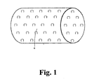
- - La fig. 1
- est une vue en élévation du boitier intermédiaire selon l'invention ;
- - La fig. 2
- est une photo d'ensemble des pièces du boitier intermédiaire de la
figure 1 ; - - La fig. 3
- représente vu de face avant le boitier intermédiaire ;
- - La fig. 4
- représente vus en éclaté les moyens de clampage de la carte électronique ;
- - La fig. 5
- représente vue de dessus la carte électronique et des composants du circuit imprimé ;
- - La fig. 6
- représente éclatés vus de côté la vis de fixation du clamp, le clamp, et la carte électronique ;
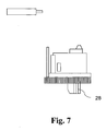
- - La fig. 7
- représente le clampage en place sur les composants de puissance ;
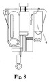
- - La fig. 8
- représente vus de côté de ¾ les composants de puissance.
- - Fig. 1
- is an elevational view of the intermediate case according to the invention;
- - Fig. 2
- is an overall picture of the parts of the intermediate case of the
figure 1 ; - - Fig. 3
- represents front view of the intermediate case;
- - Fig. 4
- shows an exploded clamping means of the electronic card;
- - Fig. 5
- represents a view from above of the electronic card and components of the printed circuit;
- - Fig. 6
- represents exploded seen from the side the fixing screw of the clamp, the clamp, and the electronic card;
- - Fig. 7
- represents the clamping in place on the power components;
- - Fig. 8
- represents from the side of ¾ the power components.
L'invention conçoit représenté sur les figures un système de motorisation 1 pour au moins un ouvrant, un ouvrant mobile muni d'au moins une paire de paumelles, sur des gonds solidaires des parois d'un ouvrage de bâtiment et jouxtant une ouverture telle que fenêtre, porte fenêtre ou analogue, comportant un moteur, un motoréducteur, logé dans un boîtier cylindrique encastrable enveloppé d'un tamis cylindrique de scellement, une carte électronique de commande avec circuit d'arrêt du moteur. Ce système de motorisation comporte un boîtier intermédiaire 2 distinct du boîtier moteur pour loger une carte électronique 3 avec des composants d'alimentation 4 du moteur, associée à une carte électronique cumulant les composants 5 de commandes, de paramétrages, de contrôle, de sécurité et de gestion de tous les services et fonctions autonomes ou dirigées, nécessaires et suffisants pour leur exécution et le fonctionnement sécurisé du système de motorisation 1.The invention conceives represented in the figures a
Le boitier intermédiaire 2 associe un tamis de scellement 6 périphérique de conformité identique à celui du boîtier moteur comme dissipateur de chaleur pour pérenniser la carte électronique 3 d'alimentation. Le boitier intermédiaire 2 est de diamètre identique à celui du boîtier moteur pour réduire l'outillage, simplifier la pose, autoriser le cas échéant sa juxtaposition avec le boîtier moteur dans une unique lumière d'encastrement de l'ouvrage de bâtiment. A cet effet avec une perforatrice et un unique trépan du diamètre du tamis tout un chacun peut soit loger bout à bout dans un unique encastrement et le boitier moteur et le boitier intermédiaire et en cas de commande manuelle suivi de cette dernière. Préférentiellement le boitier intermédiaire est dirigé vers l'intérieur pour être accessible aisément surtout en cas de volets en façades et en hauteurs.The
Le boitier intermédiaire 2 comporte au moins deux gorges 7 longitudinales réalisées dans la paroi externe 8 du boitier intermédiaire 2 pour la réception distinctes des fils d'alimentation en énergie électrique et des moyens filaires de transfert, d'échange de données avec moins un périphérique de commande et ou de contrôle de toutes ou parties des fonctions du moteur. Avantageusement les conducteurs sont protégés par le tamis ; la maintenance comme la pose s'en trouvent grandement facilitées.The
Suivant une autre variante de réalisation, l'invention prévoit encore une réalisation dans les gorges 7 de sections circulaires débouchent sur leur longueur, partiellement ou totalement, sur la paroi externe 8, réalisant ainsi une ouverture longitudinale 9 un canal configuré en C 9 de largeur suffisante pour l'insertion un à un et le maintient de fils d'alimentation en énergie électrique et de moyens filaires de transfert, d'échange de données, et en ce que les lèvres 10 du canal en C 9 et l'écartement de leur ouverture forment retenue et chacune de leur section autorise la réception de plusieurs fils et en ce que les gorges 7 sont de longueur 11 inférieure à celle 12 du boîtier 2 pour réaliser à l'arrière du couvercle 14 de boîtier 2, avec une lumière 13 traversant dans l'épaisseur dudit boîtier, un passage de fils et donc un accès dans le boîtier 2 pour permettre leur branchement sur les composants 4, 5 idoines logés sur au moins une carte 3 et ce faisant permettre une solidarisation jointive du couvercle 14 sur le boîtier 2 et un étanchéité améliorée de l'ensemble. Avantageusement la gorge a deux accès un longitudinal en l'absence du tamis et un accès terminal lorsque le tamis est posé. Les conducteurs se posent ou s'enfilent ce qui présente un confort d'installation et de maintenance. Il n'y a plus de risques de coincer ou de détériores des fils et des connections.According to another alternative embodiment, the invention also provides an embodiment in the
L'invention prévoit encore une réalisation dans laquelle le boîtier 2 comporte sur sa paroi interne 15 deux embases 16 longitudinales rapportées ou moulées avec le boîtier 2. Les embases 16 sont quasi diamétralement opposées pour autoriser une largeur maximale d'au moins un support de circuit imprimé 3 séparant le volume du boîtier 2 en au moins deux sections de volumes suffisants n'imposant aucun sens d'assemblage et ou autorisant de loger tous types de composants électroniques 4, 5 idoines à l'alimentation, l'asservissement et les connexions de tous types de périphériques externes par fils ou par ondes de tout genre.The invention also provides an embodiment in which the
Le boîtier 2 comporte traversant sur son fond 17, une lumière de fixation 18 de la platine d'installation 19 solidarisant la carte 3 sur le dit fond 17 en prenant en étau au moins un composant de puissance d'alimentation 4, générateur de chaleur, pour faire de cet assemblage un dissipateur thermique. Ledit boîtier 2 comporte en outre diamétralement opposé sur sa paroi interne et disposé longitudinalement deux cylindres 20 creux filetés surmoulés avec le boîtier 2, débouchant sur l'ouverture du boîtier sur sa face avant 21 et aptes à recevoir les vis de fixations d'un couvercle 14 de boîtier 2, typiquement, le système de motorisation comporte un boîtier intermédiaire 2 distinct du boîtier moteur dans lequel la platine d'installation 19 solidarisant la carte 3 est conçue avec deux ailes 22, 23 quasi parallèles consécutives solidarisées chacune 22 à l'autre 23 avec l'une de leur extrémité par une aile de liaison 24 de dimension adaptée à la section d'au moins un composant de puissance 4 à clamper sur le fond 17 du boîtier 2. Cette aile de liaison 24 est quasi perpendiculaire aux deux ailes parallèles 22, 23 dont une aile 22 constitue le moyen recevant la vis de fixation 25 sur le fond 17 du boitier 2 sur lequel l'aile 22 s'applique jointivement. La seconde aile 23 comporte un enduit de surface 26 amortisseur de pression et isolant pour ne pas détériorer un quelconque composant 4, 5 soit par effet mécanique soit par conduction électrique. La dite seconde aile 23 pouvant être positionnée non parallèle par rapport à la première 22 lors de la fixation et grâce à la liaison perpendiculaire 24 légèrement élastique et ce suffisamment pour permettre une inclinaison de la seconde aile 23 et réaliser un effort additionnel de solidarisation par contact d'au moins un composant de puissance 4 sur le fond 17 du boîtier 2. En effet, avantageusement, cela assure ainsi au boîtier 2 une bonne dissipation de chaleur. Ce type d'assemblage permet une intervention aisée sur la carte 3 pour son montage dans le boîtier 2 ou pour exemple, de maintenance, par la face avant du boiter 21 en toutes circonstances. Le procédé de solidarisation est réalisé avec une vis 25 de section hexagonale courante, de longueur maximale égale à la profondeur 12 du boitier 2 pour une prise en main et un positionnement aisé lors des interventions de fixation de la platine 19, ou inversement. Son extrémité comporte un filetage 27 adapté à la lumière 18 dudit fond 17 de boitier 2.The
Le support de circuit 3 imprimé a une dimension maximale délimitée par l'écartement des embases 16 du boitier 2 les plans d'extrémités internes 21, 17 du boitier, lequel support de composants 3 est un système ouvert et évolutif comportant des moyens de connexion 29 d'alimentation et ou de transfert de données, une mise à la masse, et des composants 4 d'alimentation et de transformation en basse tension auto régulée, des étages électroniques 5 pour l'apprentissage et l'intelligence électronique, le tout aux fins de commande de l'ouvrant en ouverture ou en fermeture ou en entrebâillement, pour le contrôle et l'ordonnancement des déplacements de l'ouvrant, pour la mise en sécurité de l'ouvrant en cas d'obstacles physiques ou aérauliques ou en cas de disfonctionnement de tous ordres pour la sécurité des personnes et la pérennité de l'installation. Le support de circuit imprimé 3 comporte des étages électroniques 5 autorisant le choix de périphériques externes de commande de toute nature y compris d'étages 5 permettant le codage et l'acceptation de protocoles clients avec des composants de synchronisation des dits périphériques avec le dispositif de motorisation et les autres étages électroniques 5. Il permet d'accéder à tous fonctions et services sans exclusions, support de circuit imprimé 3 comportant des étages électroniques 5 pour l'apprentissage, l'enregistrement et la conservation des paramètres acquis. Le support de circuit imprimé comporte des étages électroniques 5 pour assister certaines fonctions à paramètres avec des moyens d'incrémentation électroniques et de contrôle de diverses puissances autorisées aux fins d'une mise en route et d'une utilisation aisée pour tout utilisateur sans besoins de connaissances particulières et afin de garantir la durée de vie optimum de l'ensemble moteur et dispositif intermédiaire 2.The
L'invention comprend encore d'autres variantes de réalisation ci-dessous :The invention also comprises other variants of embodiment below:
Le circuit électronique 3 comporte des moyens de commande basculants dits « Switch » et organes de commande 28 manuels et directs pour permettre toutes interventions de base à toute opération de service ou de maintenance et autant en cas de disfonctionnement de périphériques, le tout accessible après dépôt du couvercle 17 de boitier 2.The
Un second mode de réalisation selon l'invention, consiste à réduire le diamètre dudit boitier intermédiaire 2 pour permettre son insertion jointive dans le boitier moteur dont la longueur a été adaptée à ces effets d'augmenter la capacité de dissipation de la chaleur d'une part et d'autre part, de réduire les travaux d'installation du dispositif de motorisation à un seul taraudage par moteur, ce qui est avantageux en rénovation et surtout en cas de systèmes de l'art antérieurs installés et de mise à profit des installations filaires existantes.A second embodiment according to the invention consists in reducing the diameter of said
L'avantage est optimum car la motorisation ici ne nécessite plus qu'une connexion d'alimentation lorsque la commande se fait à distance.The advantage is optimum because the motorization here requires only a power connection when the remote control.
L'invention satisfait donc les objectifs de solutions aux problèmes posés et prévoyant l'utilisation d'un boitier intermédiaire 2 conforme à celui du système de motorisations, le boîtier étant distinct d'un boitier de motorisation d'un ensemble ouvrant pivotant articulé sur des gonds pour l'automatisation du système ouvrant complet, avec échanges de données entre le système et des périphériques externes de toute nature, dont principalement des moyens de commande des fonctions acceptant tout codage ou protocole personnalisé client, comportant un boitier hermétique 2 installé avec un tamis 6 de scellement périphérique standardisé à tous les boitiers pour faire dissipateur thermique encastrable dans un ouvrage de bâtiment, lequel boitier 2 comporte un couvercle 17 d'accès au contenu, lequel contenu est au moins un support 3 de circuits électroniques pour l'alimentation transformée et autocontrôlées 4, la mise en route 5, l'apprentissage 5, la mémorisation des paramétrages de fonctionnement et de sécurité 5, le fonctionnement de services utilisateurs 5, le contrôle et l'enregistrement des opérations 5, le tout 4, 5 constituant un système ouvert et évolutif, dont les commandes peuvent être filaires, ou par ondes de toute nature, constituant en tout un système d'automatisation et dissipateur de chaleur 1, d'au moins un ouvrant adapté tant en rénovation qu'en construction neuve, apte à autoriser tous types de périphériques et toutes interventions pour quelques raisons qui soient, et apte à être posé et utilisé par toute personne sans connaissances particulières avec avantageusement tous moyens garantissant sa longévité pour un fonctionnement sécurisé.The invention thus satisfies the objectives of solutions to the problems posed and providing for the use of an intermediate housing 2 corresponding to that of the motorization system, the housing being distinct from a motor housing of a pivoting opening assembly articulated on hinges for the automation of the fully opening system, with data exchange between the system and external peripherals of any kind, mainly control means of functions accepting any coding or customized client protocol, comprising a hermetic box 2 installed with a sieve 6 peripheral sealing standardized to all cases for heat sink embedded in a building structure, which housing 2 comprises a cover 17 to access the contents, which content is at least one support 3 of electronic circuits for the transformed power supply and 4, start-up 5, learning 5, memorizing operating and safety settings 5, the operation of user services 5, the control and recording of operations 5, the whole 4, 5 constituting an open and evolutive system, whose commands can be wired, or by waves of any kind , constituting altogether an automation system and heat sink 1, of at least one suitable opening both in renovation and in new construction, able to authorize all types of peripherals and all interventions for any reasons, and suitable for be placed and used by anyone without special knowledge with advantageously all means ensuring its longevity for secure operation.
Le système de motorisation 1 selon l'invention concerne également l'utilisation pour l'automatisation de la motorisation, entre autres de volets de fenêtres, porte-fenêtre, portes ou analogues dans des ouvrages de bâtiments.The
- 11
- Système de motorisation / EnsembleMotorization System / Set
- 22
- Boitier intermédiaireIntermediate case
- 33
- Carte électronique / Circuits imprimésElectronic Card / Printed Circuit
- 44
- Composants d'alimentation, de puissancePower supply and power components
- 5.5.
- Composants de commande, contrôle, sécurité, gestion, fonctions, ... / Etages électroniquesControl components, control, security, management, functions, ... / Electronic floors
- 6.6.
- Tamis de scellementSealing sieves
- 7.7.
- Gorges longitudinalesLongitudinal gorges
- 8.8.
- Paroi externeOuter wall
- 9.9.
- ouverture longitudinale / Canal en "C"longitudinal opening / channel in "C"
- 10.10.
- LèvresLips
- 11.11.
- Longueur de gorgeThroat length
- 12.12.
- Longueur de boitier / Profondeur de boitierCase Length / Case Depth
- 13.13.
- Ouverture traversante / LumièreThrough-opening / Light
- 14.14.
- CouvercleLid
- 15.15.
- Paroi externeOuter wall
- 16.16.
- EmbasesHeaders
- 17.17.
- Fond de boitierCase back
- 18.18.
- lumière de fixation de la platinefixing light of the turntable
- 19.19.
- Platine d'installation, de fixationPlatinum installation, fixing
- 20.20.
- Cylindres surmoulés filetésThreaded overmolded cylinders
- 21.21.
- Face avant du boitierFront of the case
- 22.22.
- AileWing
- 23.23.
- Seconde aileSecond wing
- 24.24.
- Aile de liaison / Liaison perpendiculaireLinkage wing / perpendicular link
- 25.25.
- Vis de fixation hexagonaleHexagonal fixing screw
- 26.26.
- Enduit de surfaceSurface coating
- 27.27.
- FiletageThread
- 28.28.
- Switch / Organes de commandeSwitch / Ordering Devices
- 29.29.
- Connexionsconnections
Les signes de référence insérés après les caractéristiques techniques mentionnées dans les revendications ont pour seul but de faciliter la compréhension de ces dernières et n'en limitent aucunement la portée.The reference signs inserted after the technical features mentioned in the claims are only intended to facilitate the understanding of the latter and in no way limit the scope.
Claims (9)
- System of motorisation (1) for at least one leaf, an opening leaf fitted with at least one pair of hinge plates on hinge axes integral with the walls of a building structure and next to an opening such as a window, French window or similar, comprising a motor, a gear motor, arranged in a recessable cylindrical housing, enclosed in a cylindrical anchoring screen, an electronic control board with a motor cutout circuit, an intermediate housing (2) separate to the motor housing to accommodate an electronic board (3) with power supply components (4) for the motor, associated with an electronic board with all the command, setting, control, security and management components (5) for all the autonomous or controlled services and functions necessary and sufficient to their execution and the secure functioning of the motorisation system (1) characterised in that the said intermediate housing (2) includes at least two longitudinal grooves (7) formed in the outer wall (8) of the intermediate housing (2) to separately hold the power supply wires and the wire means of transferring and exchanging data with at least one peripheral for commanding and/or controlling all or part of the motor functions.
- System of motorisation (1) according to claim 1 including an intermediate housing (2) separate to the motor housing in which the intermediate housing (2) includes a peripheral anchoring screen (6) of identical conformation to that of the motor housing as a heat sink to increase the life of the electronic supply board (3), and the intermediate housing (2) is of the same diameter as that of the motor housing to reduce the tools needed, simplify installation, allow its juxtaposition, where appropriate, with the motor housing in a single recess in the building structure.
- System of motorisation (1) according to claim 2 including an intermediate housing (2) separate to the motor housing in which the circular section grooves (7) open along their length partially or totally onto the outer wall (8), thus forming a longitudinal opening (9) a C-shaped channel (9) of sufficient width to insert one by one and hold in place the power supply wires and the wire means of transferring and exchanging data, and in which the lips (10) of the C-shaped channel (9) and the width of their opening form a retaining element and each of their sections allows them to receive several wires and in which the grooves (7) are of a length (11) shorter than that (12) of the housing (2) to form at the back of the cover (14) of the housing (2), with an opening (13) passing through the thickness of the said housing, a passage for the wires and therefore an access to the housing (2) to allow them to be connected on the appropriate components (4) (5) housed on at least one board (3) and by doing so to allow the close fitting of the cover (14) on the housing (2) and a better seal for the whole assembly.
- System of motorisation (1) according to claim 1 including an intermediate housing (2) separate to the motor housing in which the housing (2) includes on its inner wall (15) two longitudinal bases (16) fixed onto or moulded into the housing (2), which bases (16) are virtually diametrically opposite each other in order to allow a maximum width of at least one printed circuit (3) holder separating the volume of the housing into at least two sections of sufficient volume not imposing any direction of assembly and/or allowing all types of electronic components (4) (5) to be housed appropriate for the power supply, control and connection of all types of external peripherals controlled by wires or any kind of waves.
- System of motorisation (1) according to claim 1 including an intermediate housing (2) separate to the motor housing in which the housing (2) includes through its back wall (17) an opening for fastening (18) the mounting plate (19) fixing the board (3) onto the said back wall (17) holding as in a vice at least one power component (4), which generates heat, to make this assembly a heat sink, which housing (2) further includes diametrically opposite on its inner wall and placed longitudinally two hollow, threaded cylinders (20) overmoulded with the housing (2), opening onto the opening of the housing in its front wall (21) and adapted to receive the fastening screws for the cover (14) of the housing (2), typically system of motorisation (1) according to claim 1 including an intermediate housing (2) separate to the motor housing in which the mounting plate (19) fixing the board (3) is designed with two flanges (22, 23) virtually parallel, consecutive and attached one (22) to the other (23) with one of their ends by a connecting flange (24) of dimensions adapted to the cross section of at least one power component (4) to be clamped onto the back wall (17) of the housing (2), which connecting flange (24) is virtually perpendicular to the two parallel flanges (22, 23) of which one flange (22) (22) constitutes the means receiving the screw (25) fastening onto the back wall (17) of the housing (2) onto which the flange (22) is closely joined whilst the second flange (23) has a pressure absorbing, insulating surface coating (26) so as not to damage any of the components (4) (5) either by mechanical action or by electrical conduction, the said second flange (23) being able to be positioned non-parallel to the first (22) at the time of fastening and thanks to the perpendicular connection (24) which is slightly elastic and sufficiently so to enable the second flange (23) to be tilted and create an additional joining effort by contact of at least one power component (4) on the back wall (17) of the housing (2) thus ensuring that the housing (2) acts as a heat sink and also allows easy intervention on the board (3) for its fitting in the housing (2) or for example, maintenance, via the front of the housing (21) in all circumstances, this joining process being accomplished with a common hexagonal section screw (25), with a maximum length equal to the depth (12) of the housing (2) for easy handling and positioning during the operation to fix the plate (19), or vice versa, its end including a thread (27) adapted to the opening (18) in the back wall (17) of the housing (2).
- System of motorisation (1) according to claim 4 including an intermediate housing (2) separate to the motor housing in which the maximum dimensions of the printed circuit (3) holder are limited by the space between the bases (16) in the housing (2) and the inner end planes (21, 7) of the housing, which component (3) holder is an open-ended and upgradable system including means of connecting (29) a power supply and/or data transfer device, an earthing device, and power supply and self-monitored low voltage transformation components (4), electronic modules (5) for learning and electronic intelligence, all for the purpose of controlling the opening, partial opening and closing of the leaf, for the control and sequencing of the movements of the leaf, for the safe operation of the leaf in the event of physical or airborne obstacles or in the event of malfunctions of any kind for the safety of people and the long life of the installation, the printed circuit (3) holder including electronic modules (5) allowing the choice of external command peripherals of any nature including modules (5) allowing the encoding and acceptance of customers' protocols with components for synchronising the said peripherals with the motorisation system and the other electronic modules (5) and also allowing access to all functions and services without exception, printed circuit (3) holder including electronic modules (5) for the learning, saving and retention of the settings acquired, printed circuit holder including electronic modules (5) to assist certain functions with settings with electronic means of incrementation and control of various power supplies authorised for the purpose of starting and easy use for any user without any need for any particular knowledge and in order to guarantee the optimum service life of the motor unit and intermediate device (2).
- System of motorisation (1) according to claims 1, 4 or 6, including an intermediate housing (2) separate to the motor housing in which the electronic circuit (3) includes switch-type control means and direct manual controls (28) to allow all basic interventions, service or maintenance operations, and also in the case of the malfunctioning of peripherals, all accessible after removing the cover (17) of the housing (2).
- System of motorisation (1) according to claims 1 to 7 including an intermediate housing (2) separate to the motor housing in which, in a second embodiment, the invention reduces the diameter of the said intermediate housing (2) to enable its joined insertion into the motor housing whose length has been adapted accordingly to increase the heat dissipation capacity on either side, to reduce the work required to install the motorisation system to a single tapping for each motor, which is advantageous in the case of renovation work and above all in prior art systems already installed as the existing wiring installations can be used.
- Use of an intermediate housing (2) conforming to that of the system of motorisation (1) according to any one of claims 1 to 8, the housing being separate to a motor housing for a leaf pivoting on hinge axes for the automation of the complete opening system with the exchanging of data between the system and external peripherals of any nature, including mainly means of controlling functions accepting any encoding or customer's own protocol, including a sealed housing (2) installed with a peripheral anchoring screen (6) standardised for all the housings to serve as a heat sink which can be built into a building structure, which housing (2) includes a cover (17) to access the contents, which contents consist of at least one holder (3) for electronic circuits for the transformed and self-monitored power supply (4), starting (5), learning (5), the storage of the operational and security settings (5), the operation of user functions (5), the control and recording of operations (5), all of which (4) (5) form an open-ended, upgradable system, which may be controlled by wires or waves of any nature, constituting together an automation and heat dissipation system (1), for at least one adapted leaf, both in renovation work and new build situations, adapted to allow all types of peripherals and all interventions for any reason whatever, and able to be installed and used by anyone without any particular knowledge with advantageously all means of guaranteeing its longevity and secure use; for the automation of the motorisation among other things of shutters for windows, French windows, doors or similar on building structures.
Applications Claiming Priority (1)
| Application Number | Priority Date | Filing Date | Title |
|---|---|---|---|
| FR0901872A FR2944550A1 (en) | 2009-04-17 | 2009-04-17 | MOTORIZATION SYSTEM FOR OPENING AND CORRESPONDING USE |
Publications (2)
| Publication Number | Publication Date |
|---|---|
| EP2243915A1 EP2243915A1 (en) | 2010-10-27 |
| EP2243915B1 true EP2243915B1 (en) | 2011-11-16 |
Family
ID=41259993
Family Applications (1)
| Application Number | Title | Priority Date | Filing Date |
|---|---|---|---|
| EP10360019A Active EP2243915B1 (en) | 2009-04-17 | 2010-04-13 | Motorisation system for a leaf and corresponding use |
Country Status (4)
| Country | Link |
|---|---|
| EP (1) | EP2243915B1 (en) |
| AT (1) | ATE533911T1 (en) |
| ES (1) | ES2377294T3 (en) |
| FR (1) | FR2944550A1 (en) |
Family Cites Families (2)
| Publication number | Priority date | Publication date | Assignee | Title |
|---|---|---|---|---|
| FR2902819B1 (en) * | 2006-05-10 | 2009-10-09 | Wimove Sarl | MECHANISM OF MOTORIZED GONDS |
| DE102006049635A1 (en) * | 2006-10-20 | 2008-04-30 | Siemens Ag | Control unit for controlling an electric motor drive unit |
-
2009
- 2009-04-17 FR FR0901872A patent/FR2944550A1/en not_active Withdrawn
-
2010
- 2010-04-13 AT AT10360019T patent/ATE533911T1/en active
- 2010-04-13 ES ES10360019T patent/ES2377294T3/en active Active
- 2010-04-13 EP EP10360019A patent/EP2243915B1/en active Active
Also Published As
| Publication number | Publication date |
|---|---|
| FR2944550A1 (en) | 2010-10-22 |
| EP2243915A1 (en) | 2010-10-27 |
| ATE533911T1 (en) | 2011-12-15 |
| ES2377294T3 (en) | 2012-03-26 |
Similar Documents
| Publication | Publication Date | Title |
|---|---|---|
| FR3000310A1 (en) | ELECTRICAL EQUIPMENT MODULE | |
| FR2916011A1 (en) | TUBULAR ACTUATOR FOR DRIVING A SCREEN AND METHOD FOR MANUFACTURING SUCH ACTUATOR | |
| WO2011001411A1 (en) | Connector for flat conductive strips, particularly flexible luminous strips having light-emitting diodes | |
| EP2016250A1 (en) | Motorised hinge mechanism | |
| EP2243915B1 (en) | Motorisation system for a leaf and corresponding use | |
| EP1710389B1 (en) | Motor drive, particularly for a motorised closing system | |
| EP0908992B1 (en) | Variable cover device for electrical cabling duct | |
| FR2968347A1 (en) | AUTOTRACTIC SLIDING OCCULTATION DEVICE | |
| WO2021161194A1 (en) | Electrical device for the motorisation of roller shutters | |
| FR2957113A1 (en) | Motorized swinging shutter-unit for use in building, has driving mechanism comprising actuator that is placed in interior housing, where mechanism is provided with output axis in direct contact with butt hinge of door leaf | |
| EP1785571B1 (en) | Motorized suspension system and use thereof | |
| EP2304155B1 (en) | Device for holding a winch or a motor of a roller shutter in a winding case, winch and case with such a device | |
| EP1912309B1 (en) | Grouping box and method of using such a box | |
| FR2991369A1 (en) | Modular device for covering joint between wall and frame of carpentry e.g. door, in building, has finishing section intended to be placed facing joint, and rabbet section to be inserted and retained in rabbet formed in edge of frame | |
| FR3122897A1 (en) | Electromagnetic headband device for system for immobilizing a leaf by electromagnetic attraction, more particularly of a door or window leaf | |
| WO2019020897A1 (en) | Multi-outlet block comprising an overhang-protection support element | |
| EP3502394B1 (en) | Assembly for motorising a shutter | |
| FR2839819A1 (en) | Clamp box for hollow closures, used to embed switch or power outlet in this closure in buildings, has pivoting units allowing rotation of clamp | |
| BE1029017B1 (en) | Lighting system integrated into the frame of a door | |
| EP1346941B1 (en) | Cable winding reel | |
| CH703892B1 (en) | electrical device connector. | |
| BE1023588B1 (en) | DOOR MADE OF A BATI AND A VANTAIL WITH A LIGHTING DEVICE | |
| EP1300539B1 (en) | End cap for roller shutter box | |
| FR2896264A1 (en) | TRUNK HOUSING FOR DRIVING MECHANISM WITH A MEANS FOR OPENING / CLOSING AT LEAST ONE FLYING DOOR | |
| EP1403993B1 (en) | Profiled element to be positioned into a dry wall with fastening means to a structural rail |
Legal Events
| Date | Code | Title | Description |
|---|---|---|---|
| PUAI | Public reference made under article 153(3) epc to a published international application that has entered the european phase |
Free format text: ORIGINAL CODE: 0009012 |
|
| AK | Designated contracting states |
Kind code of ref document: A1 Designated state(s): AT BE BG CH CY CZ DE DK EE ES FI FR GB GR HR HU IE IS IT LI LT LU LV MC MK MT NL NO PL PT RO SE SI SK SM TR |
|
| AX | Request for extension of the european patent |
Extension state: AL BA ME RS |
|
| 17P | Request for examination filed |
Effective date: 20101105 |
|
| GRAP | Despatch of communication of intention to grant a patent |
Free format text: ORIGINAL CODE: EPIDOSNIGR1 |
|
| RIC1 | Information provided on ipc code assigned before grant |
Ipc: H05K 5/02 20060101ALI20110719BHEP Ipc: E05F 15/12 20060101AFI20110719BHEP |
|
| GRAS | Grant fee paid |
Free format text: ORIGINAL CODE: EPIDOSNIGR3 |
|
| GRAA | (expected) grant |
Free format text: ORIGINAL CODE: 0009210 |
|
| AK | Designated contracting states |
Kind code of ref document: B1 Designated state(s): AT BE BG CH CY CZ DE DK EE ES FI FR GB GR HR HU IE IS IT LI LT LU LV MC MK MT NL NO PL PT RO SE SI SK SM TR |
|
| REG | Reference to a national code |
Ref country code: GB Ref legal event code: FG4D Free format text: NOT ENGLISH |
|
| REG | Reference to a national code |
Ref country code: CH Ref legal event code: EP |
|
| REG | Reference to a national code |
Ref country code: IE Ref legal event code: FG4D Free format text: LANGUAGE OF EP DOCUMENT: FRENCH |
|
| REG | Reference to a national code |
Ref country code: DE Ref legal event code: R096 Ref document number: 602010000427 Country of ref document: DE Effective date: 20120119 |
|
| REG | Reference to a national code |
Ref country code: NL Ref legal event code: VDEP Effective date: 20111116 |
|
| REG | Reference to a national code |
Ref country code: ES Ref legal event code: FG2A Ref document number: 2377294 Country of ref document: ES Kind code of ref document: T3 Effective date: 20120326 |
|
| LTIE | Lt: invalidation of european patent or patent extension |
Effective date: 20111116 |
|
| PG25 | Lapsed in a contracting state [announced via postgrant information from national office to epo] |
Ref country code: LT Free format text: LAPSE BECAUSE OF FAILURE TO SUBMIT A TRANSLATION OF THE DESCRIPTION OR TO PAY THE FEE WITHIN THE PRESCRIBED TIME-LIMIT Effective date: 20111116 Ref country code: NO Free format text: LAPSE BECAUSE OF FAILURE TO SUBMIT A TRANSLATION OF THE DESCRIPTION OR TO PAY THE FEE WITHIN THE PRESCRIBED TIME-LIMIT Effective date: 20120216 Ref country code: IS Free format text: LAPSE BECAUSE OF FAILURE TO SUBMIT A TRANSLATION OF THE DESCRIPTION OR TO PAY THE FEE WITHIN THE PRESCRIBED TIME-LIMIT Effective date: 20120316 |
|
| PG25 | Lapsed in a contracting state [announced via postgrant information from national office to epo] |
Ref country code: PT Free format text: LAPSE BECAUSE OF FAILURE TO SUBMIT A TRANSLATION OF THE DESCRIPTION OR TO PAY THE FEE WITHIN THE PRESCRIBED TIME-LIMIT Effective date: 20120316 Ref country code: HR Free format text: LAPSE BECAUSE OF FAILURE TO SUBMIT A TRANSLATION OF THE DESCRIPTION OR TO PAY THE FEE WITHIN THE PRESCRIBED TIME-LIMIT Effective date: 20111116 Ref country code: SE Free format text: LAPSE BECAUSE OF FAILURE TO SUBMIT A TRANSLATION OF THE DESCRIPTION OR TO PAY THE FEE WITHIN THE PRESCRIBED TIME-LIMIT Effective date: 20111116 Ref country code: GR Free format text: LAPSE BECAUSE OF FAILURE TO SUBMIT A TRANSLATION OF THE DESCRIPTION OR TO PAY THE FEE WITHIN THE PRESCRIBED TIME-LIMIT Effective date: 20120217 Ref country code: NL Free format text: LAPSE BECAUSE OF FAILURE TO SUBMIT A TRANSLATION OF THE DESCRIPTION OR TO PAY THE FEE WITHIN THE PRESCRIBED TIME-LIMIT Effective date: 20111116 Ref country code: SI Free format text: LAPSE BECAUSE OF FAILURE TO SUBMIT A TRANSLATION OF THE DESCRIPTION OR TO PAY THE FEE WITHIN THE PRESCRIBED TIME-LIMIT Effective date: 20111116 Ref country code: LV Free format text: LAPSE BECAUSE OF FAILURE TO SUBMIT A TRANSLATION OF THE DESCRIPTION OR TO PAY THE FEE WITHIN THE PRESCRIBED TIME-LIMIT Effective date: 20111116 Ref country code: PL Free format text: LAPSE BECAUSE OF FAILURE TO SUBMIT A TRANSLATION OF THE DESCRIPTION OR TO PAY THE FEE WITHIN THE PRESCRIBED TIME-LIMIT Effective date: 20111116 |
|
| REG | Reference to a national code |
Ref country code: IE Ref legal event code: FD4D |
|
| PG25 | Lapsed in a contracting state [announced via postgrant information from national office to epo] |
Ref country code: CY Free format text: LAPSE BECAUSE OF FAILURE TO SUBMIT A TRANSLATION OF THE DESCRIPTION OR TO PAY THE FEE WITHIN THE PRESCRIBED TIME-LIMIT Effective date: 20111116 |
|
| PG25 | Lapsed in a contracting state [announced via postgrant information from national office to epo] |
Ref country code: DK Free format text: LAPSE BECAUSE OF FAILURE TO SUBMIT A TRANSLATION OF THE DESCRIPTION OR TO PAY THE FEE WITHIN THE PRESCRIBED TIME-LIMIT Effective date: 20111116 Ref country code: CZ Free format text: LAPSE BECAUSE OF FAILURE TO SUBMIT A TRANSLATION OF THE DESCRIPTION OR TO PAY THE FEE WITHIN THE PRESCRIBED TIME-LIMIT Effective date: 20111116 Ref country code: BG Free format text: LAPSE BECAUSE OF FAILURE TO SUBMIT A TRANSLATION OF THE DESCRIPTION OR TO PAY THE FEE WITHIN THE PRESCRIBED TIME-LIMIT Effective date: 20120216 Ref country code: SK Free format text: LAPSE BECAUSE OF FAILURE TO SUBMIT A TRANSLATION OF THE DESCRIPTION OR TO PAY THE FEE WITHIN THE PRESCRIBED TIME-LIMIT Effective date: 20111116 Ref country code: IE Free format text: LAPSE BECAUSE OF FAILURE TO SUBMIT A TRANSLATION OF THE DESCRIPTION OR TO PAY THE FEE WITHIN THE PRESCRIBED TIME-LIMIT Effective date: 20111116 Ref country code: EE Free format text: LAPSE BECAUSE OF FAILURE TO SUBMIT A TRANSLATION OF THE DESCRIPTION OR TO PAY THE FEE WITHIN THE PRESCRIBED TIME-LIMIT Effective date: 20111116 |
|
| PG25 | Lapsed in a contracting state [announced via postgrant information from national office to epo] |
Ref country code: RO Free format text: LAPSE BECAUSE OF FAILURE TO SUBMIT A TRANSLATION OF THE DESCRIPTION OR TO PAY THE FEE WITHIN THE PRESCRIBED TIME-LIMIT Effective date: 20111116 Ref country code: IT Free format text: LAPSE BECAUSE OF FAILURE TO SUBMIT A TRANSLATION OF THE DESCRIPTION OR TO PAY THE FEE WITHIN THE PRESCRIBED TIME-LIMIT Effective date: 20111116 |
|
| PLBE | No opposition filed within time limit |
Free format text: ORIGINAL CODE: 0009261 |
|
| STAA | Information on the status of an ep patent application or granted ep patent |
Free format text: STATUS: NO OPPOSITION FILED WITHIN TIME LIMIT |
|
| 26N | No opposition filed |
Effective date: 20120817 |
|
| PG25 | Lapsed in a contracting state [announced via postgrant information from national office to epo] |
Ref country code: MC Free format text: LAPSE BECAUSE OF NON-PAYMENT OF DUE FEES Effective date: 20120430 |
|
| REG | Reference to a national code |
Ref country code: DE Ref legal event code: R097 Ref document number: 602010000427 Country of ref document: DE Effective date: 20120817 |
|
| PG25 | Lapsed in a contracting state [announced via postgrant information from national office to epo] |
Ref country code: MK Free format text: LAPSE BECAUSE OF FAILURE TO SUBMIT A TRANSLATION OF THE DESCRIPTION OR TO PAY THE FEE WITHIN THE PRESCRIBED TIME-LIMIT Effective date: 20111116 |
|
| PG25 | Lapsed in a contracting state [announced via postgrant information from national office to epo] |
Ref country code: FI Free format text: LAPSE BECAUSE OF FAILURE TO SUBMIT A TRANSLATION OF THE DESCRIPTION OR TO PAY THE FEE WITHIN THE PRESCRIBED TIME-LIMIT Effective date: 20111116 |
|
| PG25 | Lapsed in a contracting state [announced via postgrant information from national office to epo] |
Ref country code: MT Free format text: LAPSE BECAUSE OF FAILURE TO SUBMIT A TRANSLATION OF THE DESCRIPTION OR TO PAY THE FEE WITHIN THE PRESCRIBED TIME-LIMIT Effective date: 20111116 |
|
| REG | Reference to a national code |
Ref country code: FR Ref legal event code: TP Owner name: MANTION SAS, FR Effective date: 20140225 |
|
| PG25 | Lapsed in a contracting state [announced via postgrant information from national office to epo] |
Ref country code: TR Free format text: LAPSE BECAUSE OF FAILURE TO SUBMIT A TRANSLATION OF THE DESCRIPTION OR TO PAY THE FEE WITHIN THE PRESCRIBED TIME-LIMIT Effective date: 20111116 |
|
| PG25 | Lapsed in a contracting state [announced via postgrant information from national office to epo] |
Ref country code: SM Free format text: LAPSE BECAUSE OF FAILURE TO SUBMIT A TRANSLATION OF THE DESCRIPTION OR TO PAY THE FEE WITHIN THE PRESCRIBED TIME-LIMIT Effective date: 20111116 Ref country code: LU Free format text: LAPSE BECAUSE OF NON-PAYMENT OF DUE FEES Effective date: 20120413 |
|
| PG25 | Lapsed in a contracting state [announced via postgrant information from national office to epo] |
Ref country code: HU Free format text: LAPSE BECAUSE OF FAILURE TO SUBMIT A TRANSLATION OF THE DESCRIPTION OR TO PAY THE FEE WITHIN THE PRESCRIBED TIME-LIMIT Effective date: 20100413 |
|
| GBPC | Gb: european patent ceased through non-payment of renewal fee |
Effective date: 20140413 |
|
| PG25 | Lapsed in a contracting state [announced via postgrant information from national office to epo] |
Ref country code: GB Free format text: LAPSE BECAUSE OF NON-PAYMENT OF DUE FEES Effective date: 20140413 |
|
| REG | Reference to a national code |
Ref country code: FR Ref legal event code: PLFP Year of fee payment: 7 |
|
| REG | Reference to a national code |
Ref country code: FR Ref legal event code: PLFP Year of fee payment: 8 |
|
| REG | Reference to a national code |
Ref country code: FR Ref legal event code: PLFP Year of fee payment: 9 |
|
| REG | Reference to a national code |
Ref country code: DE Ref legal event code: R082 Ref document number: 602010000427 Country of ref document: DE Representative=s name: TAPPE, UDO, DIPL.-PHYS. DR.RER.NAT., DE |
|
| PGFP | Annual fee paid to national office [announced via postgrant information from national office to epo] |
Ref country code: FR Payment date: 20230405 Year of fee payment: 14 Ref country code: DE Payment date: 20230430 Year of fee payment: 14 Ref country code: CH Payment date: 20230502 Year of fee payment: 14 |
|
| PGFP | Annual fee paid to national office [announced via postgrant information from national office to epo] |
Ref country code: AT Payment date: 20230503 Year of fee payment: 14 |
|
| PGFP | Annual fee paid to national office [announced via postgrant information from national office to epo] |
Ref country code: BE Payment date: 20230424 Year of fee payment: 14 |
|
| PGFP | Annual fee paid to national office [announced via postgrant information from national office to epo] |
Ref country code: ES Payment date: 20230711 Year of fee payment: 14 |