EP2243915B1 - Motorisierungssystem für Öffnungselemente, und entsprechende Anwendung - Google Patents
Motorisierungssystem für Öffnungselemente, und entsprechende Anwendung Download PDFInfo
- Publication number
- EP2243915B1 EP2243915B1 EP10360019A EP10360019A EP2243915B1 EP 2243915 B1 EP2243915 B1 EP 2243915B1 EP 10360019 A EP10360019 A EP 10360019A EP 10360019 A EP10360019 A EP 10360019A EP 2243915 B1 EP2243915 B1 EP 2243915B1
- Authority
- EP
- European Patent Office
- Prior art keywords
- housing
- motor
- motorisation
- electronic
- opening
- Prior art date
- Legal status (The legal status is an assumption and is not a legal conclusion. Google has not performed a legal analysis and makes no representation as to the accuracy of the status listed.)
- Active
Links
Images


Classifications
-
- E—FIXED CONSTRUCTIONS
- E05—LOCKS; KEYS; WINDOW OR DOOR FITTINGS; SAFES
- E05F—DEVICES FOR MOVING WINGS INTO OPEN OR CLOSED POSITION; CHECKS FOR WINGS; WING FITTINGS NOT OTHERWISE PROVIDED FOR, CONCERNED WITH THE FUNCTIONING OF THE WING
- E05F15/00—Power-operated mechanisms for wings
- E05F15/60—Power-operated mechanisms for wings using electrical actuators
- E05F15/603—Power-operated mechanisms for wings using electrical actuators using rotary electromotors
- E05F15/611—Power-operated mechanisms for wings using electrical actuators using rotary electromotors for swinging wings
- E05F15/614—Power-operated mechanisms for wings using electrical actuators using rotary electromotors for swinging wings operated by meshing gear wheels, one of which being mounted at the wing pivot axis; operated by a motor acting directly on the wing pivot axis
-
- E—FIXED CONSTRUCTIONS
- E05—LOCKS; KEYS; WINDOW OR DOOR FITTINGS; SAFES
- E05F—DEVICES FOR MOVING WINGS INTO OPEN OR CLOSED POSITION; CHECKS FOR WINGS; WING FITTINGS NOT OTHERWISE PROVIDED FOR, CONCERNED WITH THE FUNCTIONING OF THE WING
- E05F11/00—Man-operated mechanisms for operating wings, including those which also operate the fastening
- E05F11/36—Man-operated mechanisms for operating wings, including those which also operate the fastening specially designed for passing through a wall
Definitions
- the present invention relates to a motorization system and its use for at least one opening a mobile opening provided with at least one pair of hinges on hinges secured to the walls of a building structure and adjacent to an opening such as window, door window or the like, comprising a motor, a geared motor, housed in a cylindrical casing embedded in a cylindrical sealing sieve, an electronic control card with an engine stop circuit for using an intermediate casing distinct from a motor housing of a hinged pivoting assembly articulated on hinges for the automation of the complete opening system, with data exchanges between the system and external peripherals of any kind, mainly control means of the functions accepting any coding or protocol custom customer, featuring a sealed case installed with a standard peripheral sealing sieve to all housings for heat sink embedded in a building structure, which housing includes a content access cover, which content is at least one electronic circuit support for the transformed power supply and self-controlled, start-up, learning, storage of operating and safety settings, operation of user services, control and recording of operations, all as an open and scalable system, whose commands
- This document D1 teaches a motorization system for at least one opening, a mobile opening with at least one pair of hinges, on hinges integral with the walls of a building structure and adjacent to an opening such as window, French window or the like, comprising a motor (30), a geared motor housed in a cylindrical insert housing wrapped with a cylindrical sealing screen, an electronic control card with an engine stop circuit, said motorization system comprising an intermediate housing separate from the motor housing for housing an electronic card with power supply components of the engine, associated with an electronic card combining the components of commands, settings, control, security and management of all services and autonomous or directed functions necessary and sufficient for their execution and the safe operation of the motorization system.
- the invention aims to solve these problems by reducing the work of buildings to one or two drilling operations against four previously and making the secure system suitable for consideration by anyone considering to undertake such engines alone.
- the invention also aims to take advantage of the existing in terms of conductors son while reducing embedding and bleeding and tools.
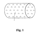
- the invention conceives represented in the figures a motorization system 1 for at least one opening, a mobile opening provided with at least one pair of hinges, on integral hinges of the walls of a building structure and adjoining an opening such as window, window-door or the like, comprising a motor, a gearmotor, housed in a cylindrical recessed casing wrapped with a cylindrical sealing sieve, an electronic control card with an engine stop circuit.
- This drive system comprises an intermediate housing 2 separate from the motor housing for housing an electronic card 3 with power supply components 4 of the engine, associated with an electronic card combining the components 5 controls, settings, control, safety and security. management of all services and autonomous or directed functions, necessary and sufficient for their execution and the safe operation of the engine system 1.
- the intermediate housing 2 combines a sealing sieve 6 peripheral compliance identical to that of the motor housing as a heat sink to perpetuate the electronic card 3 supply.
- the intermediate housing 2 is of identical diameter to that of the motor housing to reduce the tooling, simplify installation, allow where appropriate its juxtaposition with the motor housing in a single recessed light of the building structure.
- everyone can either house end to end in a single recess and the engine housing and the intermediate housing and in case of manual control followed by the latter.
- the intermediate housing is directed inwards to be easily accessible especially in case of shutters facades and heights.
- the intermediate housing 2 comprises at least two longitudinal grooves 7 made in the outer wall 8 of the intermediate housing 2 for separate reception of the electrical power supply son and wired means for transferring data exchange with less than one peripheral device. control and / or control of all or parts of the engine functions.
- the conductors are protected by the screen; maintenance and installation are greatly facilitated.
- the invention also provides an embodiment in the grooves 7 of circular sections open on their length, partially or totally, on the outer wall 8, thus providing a longitudinal opening 9 a channel configured in width C 9 sufficient for one-to-one insertion and maintains electrical power supply son and wired means for transfer, data exchange, and in that the lips 10 of the channel 9 and the spacing of their opening form restraint and each of their section allows the reception of several son and in that the grooves 7 are 11 shorter than the length 12 of the housing 2 to achieve the rear of the housing cover 14, with a light 13 passing through in the thickness of said housing, a passage of son and therefore an access in the housing 2 to allow their connection to the components 4, 5 idoines housed on at least one card 3 and thereby p make sure that the cover 14 is firmly joined to the casing 2 and that the assembly has improved sealing.
- the groove has two longitudinal accesses in the absence of the screen and a terminal access when the screen is placed. The drivers settle or slip on which presents a comfort of installation and maintenance.
- the invention also provides an embodiment in which the housing 2 comprises on its inner wall 15 two longitudinal bases 16 reported or molded with the housing 2.
- the bases 16 are substantially diametrically opposed to allow a maximum width of at least one circuit support printed 3 separating the volume of the housing 2 into at least two sections of sufficient volumes not imposing any sense of assembly and or allowing to accommodate all types of electronic components 4, 5 suitable for supply, control and connections of all types of external devices by wires or waves of any kind.
- the casing 2 includes, through its bottom 17, a fixing slot 18 of the installation plate 19 solidarizing the card 3 on the said bottom 17 by clamping at least one power supply component 4, a heat generator, to make this assembly a heat sink.
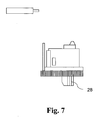
- Said housing 2 further comprises diametrically opposed on its inner wall and disposed longitudinally two threaded hollow cylinders 20 overmolded with the housing 2, opening on the opening of the housing on its front face 21 and adapted to receive the fastening screws of a cover 14 of housing 2, typically, the motorization system comprises an intermediate housing 2 separate from the motor housing in which the installation plate 19 solidarisant the card 3 is designed with two wings 22, 23 substantially parallel consecutive each secured to the other 22 23 with one of their end by a connecting wing 24 of dimension adapted to the section of at least one power component 4 to clamper on the bottom 17 of the housing 2.
- This connecting wing 24 is almost perpendicular to the two wings parallel 22, 23 including a wing 22 is the means receiving the fixing screw 25 on the bottom 17 of the housing 2 on which the flange 22 is applied contiguously.
- the second wing 23 comprises a surface coating 26 and pressure damping insulator not to damage any component 4, 5 either by mechanical effect or by electrical conduction.
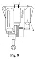
- Said second wing 23 can be positioned non-parallel with respect to the first 22 during attachment and thanks to the perpendicular connection 24 slightly elastic enough to allow an inclination of the second flange 23 and realize an additional force of contact fastening at least one power component 4 on the bottom 17 of the housing 2. In fact, advantageously, this ensures the housing 2 good heat dissipation.
- This type of assembly allows easy intervention on the card 3 for its mounting in the housing 2 or for example, maintenance, by the front of the box 21 in all circumstances.
- the joining process is carried out with a screw 25 of common hexagonal section, of maximum length equal to the depth 12 of the housing 2 for easy handling and easy positioning during fixing operations of the plate 19, or vice versa.
- Its end comprises a thread 27 adapted to the light 18 of said bottom 17 of housing 2.
- the circuit support 3 printed has a maximum dimension delimited by the spacing of the bases 16 of the housing 2 the inner end planes 21, 17 of the housing, which component support 3 is an open and scalable system comprising connecting means 29 power supply and / or data transfer, an upgrade to the mass, and components 4 supply and transformation in low voltage self-regulated electronic stages 5 for learning and electronic intelligence, all for the purpose of controlling the opening opening or closing or closing half opening, for the control and the sequencing of the displacements of the opening, for the security of the opening in the event of physical or a Vogellic obstacles or in case of malfunction of all orders for the safety of the people and the durability of installation.
- the printed circuit support 3 comprises electronic stages 5 allowing the choice of external control peripherals of any kind including stages 5 allowing the coding and the acceptance of client protocols with synchronization components of said peripherals with the device of Motorization and the other electronic stages 5. It provides access to all functions and services without exclusions, circuit board support 3 comprising electronic stages 5 for learning, recording and preservation of acquired parameters.
- the printed circuit support comprises electronic stages 5 to assist certain parameterized functions with electronic incrementation and control means of various powers allowed for easy start-up and use for any user without need for special knowledge and in order to guarantee the optimum service life of the engine and intermediate device 2.
- the electronic circuit 3 comprises tilting control means called “Switch” and control members 28 manual and direct to allow any basic operations to any service or maintenance operation and as much in case of malfunction of devices, all accessible after filing cover 17 of housing 2.
- Switch tilting control means
- control members 28 manual and direct to allow any basic operations to any service or maintenance operation and as much in case of malfunction of devices, all accessible after filing cover 17 of housing 2.
- a second embodiment according to the invention consists in reducing the diameter of said intermediate housing 2 to allow its contiguous insertion into the motor housing whose length has been adapted to these effects to increase the heat dissipation capacity of a on the one hand and on the other hand, to reduce the installation work of the motorization device to a single threading by motor, which is advantageous in renovation and especially in the case of prior art systems installed and taking advantage of the facilities existing wireline.
- the invention thus satisfies the objectives of solutions to the problems posed and providing for the use of an intermediate housing 2 corresponding to that of the motorization system, the housing being distinct from a motor housing of a pivoting opening assembly articulated on hinges for the automation of the fully opening system, with data exchange between the system and external peripherals of any kind, mainly control means of functions accepting any coding or customized client protocol, comprising a hermetic box 2 installed with a sieve 6 peripheral sealing standardized to all cases for heat sink embedded in a building structure, which housing 2 comprises a cover 17 to access the contents, which content is at least one support 3 of electronic circuits for the transformed power supply and 4, start-up 5, learning 5, memorizing operating and safety settings 5, the operation of user services 5, the control and recording of operations 5, the whole 4, 5 constituting an open and evolutive system, whose commands can be wired, or by waves of any kind , constituting altogether an automation system and heat sink 1, of at least one suitable opening both in renovation and in new construction, able to authorize all types of peripherals and all interventions for any
- the engine system 1 also relates to the use for the automation of the engine, including windows shutters, French windows, doors or the like in building structures.
Claims (9)
- Motorisierungssystem (1) für mindestens ein Öffnungselement, ein bewegliches Öffnungselement mit mindestens einem Paar Türangeln, auf Türanschlägen, die fest mit den Wandungen eines Bauwerks verbunden sind und direkt an eine Öffnung wie ein Fenster, eine Balkon- oder Terrassentür oder dergleichen angrenzen, welches einen Motor und ein Untersetzungsgetriebe aufweist, das in einem einlassbaren zylinderförmigen Gehäuse angeordnet und von einem zylinderförmigen Abschlusssieb umschlossen ist, sowie eine elektronische Steuerungskarte mit einer Schaltung zum Abschalten des Motors, sowie ein vom Motorgehäuse getrenntes zwischengeschaltetes Gehäuse (2) für zur Unterbringung einer Elektronikkarte (3) mit Bauteilen für die Stromversorgung (4) des Motors, welche einer Elektronikkarte zugeordnet ist, in welcher die Bauelemente (5) für die Steuerung, die Erkennung von Kennwerten, die Ansteuerung, die Sicherheit und die Verwaltung aller autonomen oder gelenkten Betriebsformen und Funktionen zusammengefasst sind, die für deren Ausführung und die abgesicherte Funktionsweise des Motorisierungssystems erforderlich und ausreichend sind, dadurch gekennzeichnet, dass das zwischengeschaltete Gehäuse (2) mindestens zwei in Längsrichtung verlaufende Auskehlungen (7) aufweist, die in der Außenwandung (8) des zwischengeschalteten Gehäuses (2) für die getrennte Aufnahme von Stromversorgungsleitungen und von drahtförmigen Übertragungseinrichtungen, für den Datenaustausch mit mindestens einem Steuergerät in der Peripherie und/oder Geräten zur Ansteuerung aller Funktionen des Motor oder eines Teils derselben ausgebildet sind.
- Motorisierungssystem (1) nach Anspruch 1, welches ein vom Motorgehäuse getrenntes zwischengeschaltetes Gehäuse (2) aufweist, bei welchem das zwischengeschaltete Gehäuse (2) ein peripheres Abschlusssieb (6) mit identischer Formausbildung dem Motorgehäuse als Wärmetauscher für die lange Lebensdauer der Elektronikkarte (3) zuordnet und das zwischengeschaltete Gehäuse (2) einen Durchmesser aufweist, der zur Reduzierung der Werkzeugausrüstung, zur Vereinfachung des Einbaus, gegebenenfalls zur Ermöglichung der Anordnung direkt neben dem Motorgehäuse in einer einzigen Einbauöffnung in dem Bauwerk identisch mit dem Durchmesser des Motorgehäuses ist.
- Motorisierungssystem (1) nach Anspruch 2, welches ein vom Motorgehäuse getrenntes zwischengeschaltetes Gehäuse (2) aufweist, bei welchem die Auskehlungen (7) mit kreisförmigem Querschnitt über ihre Länge teilweise oder insgesamt zur Außenwandung (8) münden und somit eine Längsöffnung (9) in einem Kanal ausbilden, der C-förmig (9) ist und eine ausreichende Breite zum Einführen von Stromversorgungsleitungen nach einander und zu deren Halterung besitzt, sowie von drahtförmigen Einrichtungen für die Übertragung von Daten und für den Datenaustausch, und dadurch gekennzeichnet, dass die Lippen (10) des C-förmigen Kanals (9) und die Beabstandung ihrer Öffnung eine Halteeinrichtung bilden und ihr jeweiliger Querschnitt die Aufnahme von mehreren Leitungen gestattet, und dass die Auskehlungen (7) eine Länge (11) besitzen, die kleiner als die Länge (11) des Gehäuses (2) ist, um so die Rückseite des Gehäuses (2) unter Ausbildung einer Längsöffnung (13) zu bilden, welche durch die Dicke des Gehäuses hindurch geht, sowie einen Durchlass für die Leitungen und somit einen Zugang in das Gehäuse (2) zu ermöglichen, um so deren Anschluss auf geeigneten Bauelementen (4) (5) auf mindestens einer Karte (3) zu gestatteten, und zwar so, dass es möglich wird, eine feste anstoßende Verbindung des Deckels (14) auf dem Gehäuse (2) und eine bessere Abdichtung der gesamten Baugruppe zu gestatten.
- Motorisierungssystem (1) nach Anspruch 1, welches ein vom Motorgehäuse getrenntes zwischengeschaltetes Gehäuse (2) aufweist, bei welchem das Gehäuse (2) auf seiner Innenwandung (15) zwei in Längsrichtung verlaufende Sockel (19) aufweist, die an dem Gehäuse (2) angesetzt oder angeformt sind, wobei die Sockel (16) sozusagen diametral einander gegenüber liegen, um eine maximale Breite von mindestens einem Träger eines Trägers einer gedruckten Schaltung (3) zu ermöglichen, wobei der Raum des Gehäuses (2) in mindestens zwei Raumabschnitte von ausreichendem Volumen getrennt wird, und dabei keinerlei Montagerichtung zwingend wird oder die Aufnahme von elektronischen Bauelementen (4) (5) jedweder Art möglich wird, die zur Versorgung, Ansteuerung und die Anschlüsse jedweder Art von externen Peripheriegeräten in verdrahteter Form oder mittels Wellen jeglicher Art geeignet sind.
- Motorisierungssystem (1) nach Anspruch 1, welches ein vom Motorgehäuse getrenntes zwischengeschaltetes Gehäuse (2) aufweist, bei welchem das Gehäuse (2) eine langgestreckte Öffnung (18) für die Befestigung der Installationsplatine (19) aufweist, welche durch den Boden (17) geführt ist, wobei die Platine die Karte (3) auf dem Boden (17) fest verbindet und dabei schraubstockartig mindestens ein Bauelement für die Versorgungsspannung (4), einen Wärmeerzeuger, um aus diesem Verbund einen Wärmeableiter zu machen, wobei das Gehäuse (2) außerdem diametral entgegengesetzt auf seiner Innenwandung in Längsrichtung angeordnet zwei hohe Zylinder (20) mit Gewinde aufweist, die auf dem Gehäuse (2) überformt sind und zur Öffnung des Gehäuses hin auf dessen Vorderseite (21) münden und zur Aufnahme von Befestigungsschrauben eines Deckels (14) des Gehäuses (2) geeignet sind, wobei im typischen Fall das Motorisierungssystem (1) ein vom Motorgehäuse getrenntes zwischengeschaltetes Gehäuse (2) aufweist, bei welchem die Installationsplatine (19), welche die Karte (3) fest verbindet, mit zwei sozusagen parallelen Flanschen (22, 23) ausgelegt ist, die auf einander folgen und jeweils mit einem ihrer Enden mittels eines Verbindungsflansches (24) fest mit einander verbunden sind, wobei dieser Verbindungsflansch eine an den Querschnitt von mindestens einem Leistungsbauteil (4) angepasst ist, das auf dem Boden (17) des Gehäuses (2) festzuspannen ist, wobei der Verbindungsflansch (24) quasi senkrecht zu den beiden parallelen Flanschen (22, 23) steht, von denen ein Flansch (22) die Einrichtung zur Aufnahme der Befestigungsschraube (25) auf dem Boden (17) des Gehäuses (2) darstellt, auf dem sich der Flansch (22) anstoßen abstützt, während der zweite Flansch (23) einen Oberflächenaufstrich (26) aufweist, welcher den Druck dämpft und isolierend wirkt, damit nicht irgendein Bauteil (4, 5) durch mechanische Einwirkung oder elektrische Leitung beschädigt wird, wobei der zweite Flansch (23) in einer Lage positioniert werden kann, die während der Befestigung nicht parallel zum ersten Flansch (22) verläuft und damit dank der senkrechten leicht elastischen Verbindung (24) in ausreichendem Maß eine Schrägstellung des zweiten Flansches (23) ermöglicht wird und eine zusätzliche Kraft zur festen Verbindung durch Kontakt von mindestens einem Leistungsbauteil (4) auf dem Boden (17) des Gehäuses (2) realisiert wird und somit ein Gehäuse (2) als Wärmeableiter gewährleistet wird und auch eine vereinfachte Möglichkeit zu Eingriffen auf der Karte (3) zu deren Montage in dem Gehäuse (2) oder beispielsweise zur Wartung über die Vorderseite des Gehäuses (21) unter allen Umständen geschaffen wird, wobei dieses Verfahren zur festen Verbindung mit einer Schraube (25) mit regelmäßigem sechseckigem Querschnitt ausgeführt wird, deren größte Länge gleich der Tiefe (12) des Gehäuses (2) zum Erfassen mit der Hand und für eine vereinfachte Positionierung bei Eingriffen zur Befestigung der Platine (19) ist oder umgekehrt deren Ende ein Gewinde (27) aufweist, das an die langgestreckte Öffnung (18) im Boden (17) des Gehäuses (2) angepasst ist.
- Motorisierungssystem (1) nach Anspruch 4, welches ein vom Motorgehäuse getrenntes zwischengeschaltetes Gehäuse (2) aufweist, bei welchem der Träger mit der gedruckten Schaltung (3) eine maximale Größe aufweist, die durch den Abstand der Sockel (16) des Gehäuses (2) von den Ebenen der innen liegenden Enden (21, 7) des Gehäuses begrenzt ist, wobei der Bauteilträger (3) ein offenes System mit Entwicklungspotential darstellt und Einrichtungen für die elektrische Verbindung (29) zur Versorgung oder für die Datenübertragung, eine Erdung und Bauelemente (4) zur Versorgung und selbstgeregelte Umwandlung in Niederspannung sowie Elektronikstufen (5) für Lernfunktionen und die elektronische Intelligenz aufweist, wobei diese Einrichtungen insgesamt zum Zwecke der Steuerung des Öffnungsteils zum Öffnen oder Schließen oder Offenstehen, zur Ansteuerung und Vorbereitung der Verlagerungen des Öffnungsteils, zur Absicherung des Öffnungsteils im Falle physikalischer oder lufttechnischer Hindernisse oder im Falle von Funktionsstörungen jeglicher Größenordnung für die Sicherheit von Personen und die fortgesetzte Funktionsfähigkeit der Anlage vorgesehen sind, wobei der Träger (3) für die gedruckte Schaltung Elektronikstufen (5) aufweist, welche die Auswahl externer Peripheriegeräte zur Steuerung jedweder Art aufweist, einschließlich von Stufen (5), welche die Kodierung und Annahme von Kundenprotokollen mit Bauelementen zur Synchronisierung der peripheren Geräte mit der Motorisierungsvorrichtung und den anderen Elektronikstufen (5) gestatten und darüber hinaus den Zugriff auf alle Funktionen und Dienste, ohne Ausschlüsse, ermöglichen, wobei der Träger (3) mit der gedruckten Schaltung Elektronikstufen (5) für eine Lernfunktion, die Registrierung und Speicherung von erfassten Parametern aufweist, wobei der Träger mit der gedruckten Schaltung Elektronikstufen (5) zur Unterstützung bestimmter Funktionen mit Parametern aufweist, mit elektronischen Einrichtungen zur Hochschaltung und zur Steuerung verschiedener zulässiger Leistungsstufen zur Inbetriebnahme und vereinfachten Verwendung für jeden Benutzer ohne Erfordernis spezieller Kenntnisse, und um die optimale Lebensdauer der gesamten Baugruppe aus Motor und zwischengeschalteter Vorrichtung (2) zu gewährleisten.
- Motorisierungssystem (1) nach den Ansprüchen 1, 4 oder 6, welches ein vom Motorgehäuse getrenntes zwischengeschaltetes Gehäuse (2) aufweist, bei welchem die elektronische Schaltung (3) Einrichtungen zur kippbaren Steuerung, sogenannten "Switches" aufweist, sowie Betätigungselemente (28) zur manuellen und direkten Betätigung, um jegliche Grundeingriffe bei jeder Service- oder Wartungsarbeit und vor allem bei Funktionsstörungen an den Peripheriegeräten zu ermöglichen, wobei das gesamte System nach dem Ablegen des Deckels (17) des Gehäuses (2) zugänglich ist.
- Motorisierungssystem (1) nach einem der Ansprüche 1 bis 7, welches ein vom Motorgehäuse getrenntes zwischengeschaltetes Gehäuse (2) aufweist, bei welchem in einer zweiten Ausführungsform die Erfindung den Durchmesser des zwischengeschalteten Gehäuses (2) verringert, um so dessen Einsetzen bzw. Anschließen in dem Motorgehäuse zu ermöglichen, dessen Länge zu diesem Zweck angepasst wurde, um so die Wärmeabstrahlfähigkeit zu beiden Seiten zu erhöhen, um die Arbeiten beim Einbau der Motorisierungseinrichtung auf das motorisierte Schneiden eines einzigen Innengewindes zu verringern, was bei Renovierung und vor allem bei bereits eingebauten Systemen nach dem Stand der Technik und zur Nutzung schon vorhandener Drahtinstallationen von Vorteil ist.
- Verwendung eines zwischengeschalteten Gehäuses (2) entsprechend dem zwischengeschalteten Gehäuse bei dem Motorisierungssystem (1) nach den Ansprüchen 1 bis 8, wobei das Gehäuse getrennt von einem Motorisierungsgehäuse einer Baugruppe zum Öffnen unter Verschwenken vorgesehen ist, die auf Angeln zur Automatisierung des gesamten Öffnungssystems angelenkt ist, mit Datenaustausch zwischen dem System und externen peripheren Geräten jedweder Art, deren Einrichtungen zu Steuerung der Funktionen in erster Linie jegliche personalisierte Kodierung eines Kunden oder jedwedes personalisiertes Kundenprotokoll akzeptieren, welches ein mit einem peripheren zylinderförmigen Abschlusssieb eingebautes hermetisch abgeschlossenes Gehäuse (2) aufweist, das für alle Gehäuse standardisiert ist, um einen einlassbaren Wärmeableiter in einem Bauwerk zu bilden, wobei das Gehäuse (2) einen Deckel (17) für den Zugriff zu seinem Inhalt aufweist, der mindestens aus einem Träger (3) für elektronische Schaltungen für die transformierte und selbstgeregelte Stromversorgung (4), die Inbetriebnahme (5), eine Lernfunktion (5), die Abspeicherung von Betriebsparametern und Sicherheitsparametern (5), den Betrieb von Benutzerdiensten (5), die Steuerung und Aufzeichnung von Arbeitsgängen (5) besteht, wobei diese in ihrer Gesamtheit (4) (5) ein offenes und entwicklungsfähiges System bilden, deren Ansteuerungen über Drahtverbindungen oder über Wellen jedweder Art sein können und insgesamt ein System zur Automatisierung und zur Wärmeabstrahlung (1) für mindestens ein Öffnungselement bilden, das sowohl bei Renovierung als auch bei Neubau einsetzbar und in der Lage ist, alle Arten von peripheren Geräten und von jeglichen Eingriffen aus welchen Gründen auch immer zu gestatten und von jedermann ohne besondere Kenntnisse in vorteilhafter Weise eingebaut und eingesetzt werden kann, wobei alle Einrichtungen die lange Lebensdauer für einen sicheren Betrieb gewährleisten, zur Automatisierung der Motorisierung unter anderem von Fensterläden, Balkon- und Terrassentüren, Türen oder ähnlichen Bauteilen in Bauwerken.
Applications Claiming Priority (1)
| Application Number | Priority Date | Filing Date | Title |
|---|---|---|---|
| FR0901872A FR2944550A1 (fr) | 2009-04-17 | 2009-04-17 | Systeme de motorisation pour ouvrant et utilisation correspondante |
Publications (2)
| Publication Number | Publication Date |
|---|---|
| EP2243915A1 EP2243915A1 (de) | 2010-10-27 |
| EP2243915B1 true EP2243915B1 (de) | 2011-11-16 |
Family
ID=41259993
Family Applications (1)
| Application Number | Title | Priority Date | Filing Date |
|---|---|---|---|
| EP10360019A Active EP2243915B1 (de) | 2009-04-17 | 2010-04-13 | Motorisierungssystem für Öffnungselemente, und entsprechende Anwendung |
Country Status (4)
| Country | Link |
|---|---|
| EP (1) | EP2243915B1 (de) |
| AT (1) | ATE533911T1 (de) |
| ES (1) | ES2377294T3 (de) |
| FR (1) | FR2944550A1 (de) |
Family Cites Families (2)
| Publication number | Priority date | Publication date | Assignee | Title |
|---|---|---|---|---|
| FR2902819B1 (fr) * | 2006-05-10 | 2009-10-09 | Wimove Sarl | Mecanisme de gonds motorises |
| DE102006049635A1 (de) * | 2006-10-20 | 2008-04-30 | Siemens Ag | Steuereinheit zum Steuern einer elektromotorischen Antriebseinheit |
-
2009
- 2009-04-17 FR FR0901872A patent/FR2944550A1/fr not_active Withdrawn
-
2010
- 2010-04-13 ES ES10360019T patent/ES2377294T3/es active Active
- 2010-04-13 EP EP10360019A patent/EP2243915B1/de active Active
- 2010-04-13 AT AT10360019T patent/ATE533911T1/de active
Also Published As
| Publication number | Publication date |
|---|---|
| ATE533911T1 (de) | 2011-12-15 |
| EP2243915A1 (de) | 2010-10-27 |
| ES2377294T3 (es) | 2012-03-26 |
| FR2944550A1 (fr) | 2010-10-22 |
Similar Documents
| Publication | Publication Date | Title |
|---|---|---|
| FR3000310A1 (fr) | Module d'appareillage electrique | |
| FR2916011A1 (fr) | Actionneur tubulaire d'entrainement d'un ecran et procede de fabrication d'un tel actionneur | |
| EP2449636A1 (de) | Steckverbinder für flache leitfähige streifen, insbesondere flexible leuchtstreifen mit leds | |
| EP2016250A1 (de) | Motorisierter scharniermechanismus | |
| EP2243915B1 (de) | Motorisierungssystem für Öffnungselemente, und entsprechende Anwendung | |
| EP1710389B1 (de) | Motorantriebsvorrichtung, insbesondere für eine motorisierten Verschlusseinrichtung | |
| EP0908992B1 (de) | Vorrichtung zur variablen Abdeckung von elektrischen kabelführungen | |
| EP1059409B1 (de) | Antriebsgetriebe für Schlossnuss | |
| FR2991369A1 (fr) | Dispositif modulaire de recouvrement d'un joint | |
| FR2968347A1 (fr) | Dispositif d'occultation coulissant autotracte | |
| WO2021161194A1 (fr) | Dispositif électrique pour la motorisation de volets roulants | |
| FR2957113A1 (fr) | Bloc volet battant motorise | |
| EP2304155B1 (de) | Haltevorrichtung für winde oder motor eines rollladens in einem aufrollgehäuse, winde und gehäuse mit derartiger vorrichtung | |
| EP1912309B1 (de) | Gruppiergehäuse und derartige Verwendung | |
| FR3122897A1 (fr) | Dispositif de bandeau électromagnétique pour système d’immobilisation de battant par attraction électromagnétique, plus particulièrement de battant de porte ou fenêtre | |
| WO2019020897A1 (fr) | Bloc multi-appareillages avec élément d'appui anti porte-à-faux | |
| EP3502394B1 (de) | Motorisierungsanlage für fensterladen | |
| FR2839819A1 (fr) | Boitier a brides pour cloisons creuses | |
| BE1029017B1 (fr) | Système d'éclairage intégré au dormant d'une porte | |
| CH703892B1 (fr) | Connecteur pour appareil électrique. | |
| BE1023588B1 (fr) | Porte formee d'un bati et d'un vantail dote d'un dispositif d'eclairage | |
| EP1785571A2 (de) | Motorisiertes Aufhängungssystem und dessen Verwendung | |
| EP1300539B1 (de) | Endverschlusskappe für einen Rolladenkasten | |
| FR2896264A1 (fr) | Boitier coffre pour mecanisme d'entrainement d'un moyen d'ouverture/fermeture d'au moins un volet battant | |
| EP1403993B1 (de) | Profilelement zum Einbau in einer Wand mit Befestigungsmitteln an einer Strukturschiene |
Legal Events
| Date | Code | Title | Description |
|---|---|---|---|
| PUAI | Public reference made under article 153(3) epc to a published international application that has entered the european phase |
Free format text: ORIGINAL CODE: 0009012 |
|
| AK | Designated contracting states |
Kind code of ref document: A1 Designated state(s): AT BE BG CH CY CZ DE DK EE ES FI FR GB GR HR HU IE IS IT LI LT LU LV MC MK MT NL NO PL PT RO SE SI SK SM TR |
|
| AX | Request for extension of the european patent |
Extension state: AL BA ME RS |
|
| 17P | Request for examination filed |
Effective date: 20101105 |
|
| GRAP | Despatch of communication of intention to grant a patent |
Free format text: ORIGINAL CODE: EPIDOSNIGR1 |
|
| RIC1 | Information provided on ipc code assigned before grant |
Ipc: H05K 5/02 20060101ALI20110719BHEP Ipc: E05F 15/12 20060101AFI20110719BHEP |
|
| GRAS | Grant fee paid |
Free format text: ORIGINAL CODE: EPIDOSNIGR3 |
|
| GRAA | (expected) grant |
Free format text: ORIGINAL CODE: 0009210 |
|
| AK | Designated contracting states |
Kind code of ref document: B1 Designated state(s): AT BE BG CH CY CZ DE DK EE ES FI FR GB GR HR HU IE IS IT LI LT LU LV MC MK MT NL NO PL PT RO SE SI SK SM TR |
|
| REG | Reference to a national code |
Ref country code: GB Ref legal event code: FG4D Free format text: NOT ENGLISH |
|
| REG | Reference to a national code |
Ref country code: CH Ref legal event code: EP |
|
| REG | Reference to a national code |
Ref country code: IE Ref legal event code: FG4D Free format text: LANGUAGE OF EP DOCUMENT: FRENCH |
|
| REG | Reference to a national code |
Ref country code: DE Ref legal event code: R096 Ref document number: 602010000427 Country of ref document: DE Effective date: 20120119 |
|
| REG | Reference to a national code |
Ref country code: NL Ref legal event code: VDEP Effective date: 20111116 |
|
| REG | Reference to a national code |
Ref country code: ES Ref legal event code: FG2A Ref document number: 2377294 Country of ref document: ES Kind code of ref document: T3 Effective date: 20120326 |
|
| LTIE | Lt: invalidation of european patent or patent extension |
Effective date: 20111116 |
|
| PG25 | Lapsed in a contracting state [announced via postgrant information from national office to epo] |
Ref country code: LT Free format text: LAPSE BECAUSE OF FAILURE TO SUBMIT A TRANSLATION OF THE DESCRIPTION OR TO PAY THE FEE WITHIN THE PRESCRIBED TIME-LIMIT Effective date: 20111116 Ref country code: NO Free format text: LAPSE BECAUSE OF FAILURE TO SUBMIT A TRANSLATION OF THE DESCRIPTION OR TO PAY THE FEE WITHIN THE PRESCRIBED TIME-LIMIT Effective date: 20120216 Ref country code: IS Free format text: LAPSE BECAUSE OF FAILURE TO SUBMIT A TRANSLATION OF THE DESCRIPTION OR TO PAY THE FEE WITHIN THE PRESCRIBED TIME-LIMIT Effective date: 20120316 |
|
| PG25 | Lapsed in a contracting state [announced via postgrant information from national office to epo] |
Ref country code: PT Free format text: LAPSE BECAUSE OF FAILURE TO SUBMIT A TRANSLATION OF THE DESCRIPTION OR TO PAY THE FEE WITHIN THE PRESCRIBED TIME-LIMIT Effective date: 20120316 Ref country code: HR Free format text: LAPSE BECAUSE OF FAILURE TO SUBMIT A TRANSLATION OF THE DESCRIPTION OR TO PAY THE FEE WITHIN THE PRESCRIBED TIME-LIMIT Effective date: 20111116 Ref country code: SE Free format text: LAPSE BECAUSE OF FAILURE TO SUBMIT A TRANSLATION OF THE DESCRIPTION OR TO PAY THE FEE WITHIN THE PRESCRIBED TIME-LIMIT Effective date: 20111116 Ref country code: GR Free format text: LAPSE BECAUSE OF FAILURE TO SUBMIT A TRANSLATION OF THE DESCRIPTION OR TO PAY THE FEE WITHIN THE PRESCRIBED TIME-LIMIT Effective date: 20120217 Ref country code: NL Free format text: LAPSE BECAUSE OF FAILURE TO SUBMIT A TRANSLATION OF THE DESCRIPTION OR TO PAY THE FEE WITHIN THE PRESCRIBED TIME-LIMIT Effective date: 20111116 Ref country code: SI Free format text: LAPSE BECAUSE OF FAILURE TO SUBMIT A TRANSLATION OF THE DESCRIPTION OR TO PAY THE FEE WITHIN THE PRESCRIBED TIME-LIMIT Effective date: 20111116 Ref country code: LV Free format text: LAPSE BECAUSE OF FAILURE TO SUBMIT A TRANSLATION OF THE DESCRIPTION OR TO PAY THE FEE WITHIN THE PRESCRIBED TIME-LIMIT Effective date: 20111116 Ref country code: PL Free format text: LAPSE BECAUSE OF FAILURE TO SUBMIT A TRANSLATION OF THE DESCRIPTION OR TO PAY THE FEE WITHIN THE PRESCRIBED TIME-LIMIT Effective date: 20111116 |
|
| REG | Reference to a national code |
Ref country code: IE Ref legal event code: FD4D |
|
| PG25 | Lapsed in a contracting state [announced via postgrant information from national office to epo] |
Ref country code: CY Free format text: LAPSE BECAUSE OF FAILURE TO SUBMIT A TRANSLATION OF THE DESCRIPTION OR TO PAY THE FEE WITHIN THE PRESCRIBED TIME-LIMIT Effective date: 20111116 |
|
| PG25 | Lapsed in a contracting state [announced via postgrant information from national office to epo] |
Ref country code: DK Free format text: LAPSE BECAUSE OF FAILURE TO SUBMIT A TRANSLATION OF THE DESCRIPTION OR TO PAY THE FEE WITHIN THE PRESCRIBED TIME-LIMIT Effective date: 20111116 Ref country code: CZ Free format text: LAPSE BECAUSE OF FAILURE TO SUBMIT A TRANSLATION OF THE DESCRIPTION OR TO PAY THE FEE WITHIN THE PRESCRIBED TIME-LIMIT Effective date: 20111116 Ref country code: BG Free format text: LAPSE BECAUSE OF FAILURE TO SUBMIT A TRANSLATION OF THE DESCRIPTION OR TO PAY THE FEE WITHIN THE PRESCRIBED TIME-LIMIT Effective date: 20120216 Ref country code: SK Free format text: LAPSE BECAUSE OF FAILURE TO SUBMIT A TRANSLATION OF THE DESCRIPTION OR TO PAY THE FEE WITHIN THE PRESCRIBED TIME-LIMIT Effective date: 20111116 Ref country code: IE Free format text: LAPSE BECAUSE OF FAILURE TO SUBMIT A TRANSLATION OF THE DESCRIPTION OR TO PAY THE FEE WITHIN THE PRESCRIBED TIME-LIMIT Effective date: 20111116 Ref country code: EE Free format text: LAPSE BECAUSE OF FAILURE TO SUBMIT A TRANSLATION OF THE DESCRIPTION OR TO PAY THE FEE WITHIN THE PRESCRIBED TIME-LIMIT Effective date: 20111116 |
|
| PG25 | Lapsed in a contracting state [announced via postgrant information from national office to epo] |
Ref country code: RO Free format text: LAPSE BECAUSE OF FAILURE TO SUBMIT A TRANSLATION OF THE DESCRIPTION OR TO PAY THE FEE WITHIN THE PRESCRIBED TIME-LIMIT Effective date: 20111116 Ref country code: IT Free format text: LAPSE BECAUSE OF FAILURE TO SUBMIT A TRANSLATION OF THE DESCRIPTION OR TO PAY THE FEE WITHIN THE PRESCRIBED TIME-LIMIT Effective date: 20111116 |
|
| PLBE | No opposition filed within time limit |
Free format text: ORIGINAL CODE: 0009261 |
|
| STAA | Information on the status of an ep patent application or granted ep patent |
Free format text: STATUS: NO OPPOSITION FILED WITHIN TIME LIMIT |
|
| 26N | No opposition filed |
Effective date: 20120817 |
|
| PG25 | Lapsed in a contracting state [announced via postgrant information from national office to epo] |
Ref country code: MC Free format text: LAPSE BECAUSE OF NON-PAYMENT OF DUE FEES Effective date: 20120430 |
|
| REG | Reference to a national code |
Ref country code: DE Ref legal event code: R097 Ref document number: 602010000427 Country of ref document: DE Effective date: 20120817 |
|
| PG25 | Lapsed in a contracting state [announced via postgrant information from national office to epo] |
Ref country code: MK Free format text: LAPSE BECAUSE OF FAILURE TO SUBMIT A TRANSLATION OF THE DESCRIPTION OR TO PAY THE FEE WITHIN THE PRESCRIBED TIME-LIMIT Effective date: 20111116 |
|
| PG25 | Lapsed in a contracting state [announced via postgrant information from national office to epo] |
Ref country code: FI Free format text: LAPSE BECAUSE OF FAILURE TO SUBMIT A TRANSLATION OF THE DESCRIPTION OR TO PAY THE FEE WITHIN THE PRESCRIBED TIME-LIMIT Effective date: 20111116 |
|
| PG25 | Lapsed in a contracting state [announced via postgrant information from national office to epo] |
Ref country code: MT Free format text: LAPSE BECAUSE OF FAILURE TO SUBMIT A TRANSLATION OF THE DESCRIPTION OR TO PAY THE FEE WITHIN THE PRESCRIBED TIME-LIMIT Effective date: 20111116 |
|
| REG | Reference to a national code |
Ref country code: FR Ref legal event code: TP Owner name: MANTION SAS, FR Effective date: 20140225 |
|
| PG25 | Lapsed in a contracting state [announced via postgrant information from national office to epo] |
Ref country code: TR Free format text: LAPSE BECAUSE OF FAILURE TO SUBMIT A TRANSLATION OF THE DESCRIPTION OR TO PAY THE FEE WITHIN THE PRESCRIBED TIME-LIMIT Effective date: 20111116 |
|
| PG25 | Lapsed in a contracting state [announced via postgrant information from national office to epo] |
Ref country code: SM Free format text: LAPSE BECAUSE OF FAILURE TO SUBMIT A TRANSLATION OF THE DESCRIPTION OR TO PAY THE FEE WITHIN THE PRESCRIBED TIME-LIMIT Effective date: 20111116 Ref country code: LU Free format text: LAPSE BECAUSE OF NON-PAYMENT OF DUE FEES Effective date: 20120413 |
|
| PG25 | Lapsed in a contracting state [announced via postgrant information from national office to epo] |
Ref country code: HU Free format text: LAPSE BECAUSE OF FAILURE TO SUBMIT A TRANSLATION OF THE DESCRIPTION OR TO PAY THE FEE WITHIN THE PRESCRIBED TIME-LIMIT Effective date: 20100413 |
|
| GBPC | Gb: european patent ceased through non-payment of renewal fee |
Effective date: 20140413 |
|
| PG25 | Lapsed in a contracting state [announced via postgrant information from national office to epo] |
Ref country code: GB Free format text: LAPSE BECAUSE OF NON-PAYMENT OF DUE FEES Effective date: 20140413 |
|
| REG | Reference to a national code |
Ref country code: FR Ref legal event code: PLFP Year of fee payment: 7 |
|
| REG | Reference to a national code |
Ref country code: FR Ref legal event code: PLFP Year of fee payment: 8 |
|
| REG | Reference to a national code |
Ref country code: FR Ref legal event code: PLFP Year of fee payment: 9 |
|
| REG | Reference to a national code |
Ref country code: DE Ref legal event code: R082 Ref document number: 602010000427 Country of ref document: DE Representative=s name: TAPPE, UDO, DIPL.-PHYS. DR.RER.NAT., DE |
|
| PGFP | Annual fee paid to national office [announced via postgrant information from national office to epo] |
Ref country code: FR Payment date: 20230405 Year of fee payment: 14 Ref country code: DE Payment date: 20230430 Year of fee payment: 14 Ref country code: CH Payment date: 20230502 Year of fee payment: 14 |
|
| PGFP | Annual fee paid to national office [announced via postgrant information from national office to epo] |
Ref country code: AT Payment date: 20230503 Year of fee payment: 14 |
|
| PGFP | Annual fee paid to national office [announced via postgrant information from national office to epo] |
Ref country code: BE Payment date: 20230424 Year of fee payment: 14 |
|
| PGFP | Annual fee paid to national office [announced via postgrant information from national office to epo] |
Ref country code: ES Payment date: 20230711 Year of fee payment: 14 |