EP2243209B1 - A rotor for an electrical machin - Google Patents
A rotor for an electrical machin Download PDFInfo
- Publication number
- EP2243209B1 EP2243209B1 EP09700730.6A EP09700730A EP2243209B1 EP 2243209 B1 EP2243209 B1 EP 2243209B1 EP 09700730 A EP09700730 A EP 09700730A EP 2243209 B1 EP2243209 B1 EP 2243209B1
- Authority
- EP
- European Patent Office
- Prior art keywords
- rotor
- magnets
- radially
- rotor portion
- apertures
- Prior art date
- Legal status (The legal status is an assumption and is not a legal conclusion. Google has not performed a legal analysis and makes no representation as to the accuracy of the status listed.)
- Active
Links
Images


Classifications
-
- H—ELECTRICITY
- H02—GENERATION; CONVERSION OR DISTRIBUTION OF ELECTRIC POWER
- H02K—DYNAMO-ELECTRIC MACHINES
- H02K1/00—Details of the magnetic circuit
- H02K1/06—Details of the magnetic circuit characterised by the shape, form or construction
- H02K1/22—Rotating parts of the magnetic circuit
- H02K1/27—Rotor cores with permanent magnets
- H02K1/2793—Rotors axially facing stators
- H02K1/2795—Rotors axially facing stators the rotor consisting of two or more circumferentially positioned magnets
-
- H—ELECTRICITY
- H02—GENERATION; CONVERSION OR DISTRIBUTION OF ELECTRIC POWER
- H02K—DYNAMO-ELECTRIC MACHINES
- H02K1/00—Details of the magnetic circuit
- H02K1/06—Details of the magnetic circuit characterised by the shape, form or construction
- H02K1/22—Rotating parts of the magnetic circuit
- H02K1/28—Means for mounting or fastening rotating magnetic parts on to, or to, the rotor structures
- H02K1/30—Means for mounting or fastening rotating magnetic parts on to, or to, the rotor structures using intermediate parts, e.g. spiders
Definitions
- This invention relates to a rotor for an axial-flux electrical machine. More particularly, but not exclusively, this invention relates to a rotor for an axial-flux electrical machine for use in a hybrid vehicle or a purely electric vehicle.
- Hybrid vehicles are vehicles in which two power sources, for example an internal combustion engine and an electric motor, play a part in supplying power for use in automotive propulsion.
- both the engine and the motor are connectable to driveline components for supplying rotary power to wheels for driving the vehicle.
- the motor is connectable to the driveline components for supplying the rotary power; and the engine is used only as a prime mover for driving a generator which generates the electrical power needed to operate the motor.
- Examples of existing hybrid vehicles include passenger cars (sometimes referred to as "automobiles"), vans, buses and light trucks.
- automobiles vans, buses and light trucks.
- the aperture may be an aperture completely through the rotor from one side to the other.
- the aperture may be a blind aperture, such as a recess.
- Material of the rotor may also abut each magnet so as to locate the magnet substantially axially in at least one axial direction. Material of the rotor may abut each magnet so as to locate the magnet substantially axially in both axial directions. Material of the rotor may also abut each magnet so as to locate the magnet substantially radially in one, at least one, or both, radial directions.
- the rotor may be formed of more than one piece.
- the rotor may include a first rotor portion and a second rotor portion.
- the arrangement may be such that fitting the second rotor portion to the first rotor portion, with the magnets therebetween, locates the magnets therebetween substantially tangentially, substantially radially and substantially axially in at least one axial direction.
- the first and second rotor portions may be arranged to encase the magnets therebetween axially.
- Each rotor portion may include apertures therethrough, each aperture sized to receive a respective magnet.
- Each rotor portion may be provided with abutment means adjacent the aperture to abut a magnet received therein so as to prevent it passing through the aperture.
- the abutment means may be adjacent one face of the respective rotor portion.
- the abutment means may serve to narrow the aperture.
- the abutment means may include at least one lip.
- the first and second rotor portions may be arranged to encase the magnets therebetween radially.
- the first rotor portion may be arranged to abut the magnets in substantially both circumferential directions and one radial direction.
- the second rotor portion may be arranged to abut at least some of the magnets substantially in the other radial direction.
- the first rotor portion may have the apertures formed therein.
- the second rotor portion may be a substantially annular portion, or a segment of a substantially annular portion, that is arranged to surround all, or a segment of, the first portion with the magnets received therein.
- the second rotor portion may be formed of tape wound around the first rotor portion.
- the second rotor portion may be provided by a retaining ring.
- the retaining ring may be of the same material as the first rotor potion.
- the magnets and/or the first portion may be provided with structure that locates the magnets axially.
- the magnets and the first portion may be provided with cooperating structure that cooperates to locate the magnets radially.
- the structure On the first portion, the structure may be provided in one or more side walls of the apertures. On the magnets, the structure may be provided in one or more side walls thereof.
- the cooperating structure may include a tongue-and-groove arrangement.
- Two magnets may be received in each aperture.
- the two magnets may be axially juxtaposed.
- the rotor may be arranged to receive a first one of the two magnets in a first axial direction and a second one of the two magnets in a second axial direction.
- One or more sidewalls of each aperture may include an abutment against which one or both of the respective magnets abuts when received in the aperture.
- the abutment may be a lip.
- the two magnets in each aperture may be magnetised so as to attract one another, thereby providing axial location.
- the magnets may be magnetised such that one of each magnet in each aperture has a North-seeking pole facing axially inwards and the respective other magnet has a South-seeking pole facing axially inwards.
- Each magnet may be fixed on the rotor by an adhesive material provided between each magnet and material of the rotor.
- the adhesive material may be a glue.
- Each magnet may be flush with surrounding material of the rotor on one or each side of the rotor.
- the rotor may be of a magnetically and/or electrically insulating material. This assists in avoiding losses in the rotor, such as losses due to eddy currents, and assists in avoiding magnetic short circuits in the flux path.
- the rotor may be of a heat insulating material and may be resistant to high temperatures.
- the rotor may be of a composite material.
- the rotor may be a substantially flat disc with apertures formed therein, each aperture sized to receive a respective magnet.
- each magnet fits in the respective aperture such that surrounding material of the rotor acts to locate the magnet radially, in one or both radial directions, and circumferentially.
- the amount of magnetised material at angular locations of the rotor, for a given rotor thickness is maximised.
- the strength of the excitation field set up by the permanent magnets is maximised for a given rotor thickness, thereby increasing the power density.
- an axial-flux electrical machine having at least one rotor according to the first aspect.
- FIG. 1 shows a rotor 200 for use in an axial-flux electrical machine.
- the rotor 200 is a generally flat, thin, disc. It is formed from a composite material, which, in this embodiment, is a glass-fibre-and-resin-based cross-laminated material.
- the composite material is a good electrical insulator and a good thermal insulator.
- the rotor 200 has a central, round, aperture 210 through it.
- a series of smaller apertures 215 are formed through the rotor 200 in positions adjacent the central aperture 210 and so as to form, collectively, a ring around the central aperture 210 that is concentric with the central aperture 210 about the rotational axis of the rotor 200.
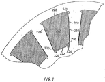
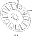
- the rotor 200 of Figure 1 includes twelve apertures 220 therethrough, each aperture being shaped like a segment of a flattened, planar, ring. Each of these apertures 220 is arranged adjacent the radially-outer edge of the rotor 200, and so as to be concentric therewith.
- the twelve apertures 220 are distributed around the rotor 200 with constant angular pitch. As is shown in Figure 2 , each of the twelve apertures 220 has two concentric arcuate sidewalls 222, concentric with the rotor 200, and two straight sidewalls 224 in-between the arcuate sides and extending radially.
- sidewalls of the apertures 220 are slightly recessed along much of their length with respect to the ends of the sidewalls. This is true of the radially-innermost of the arcuate sidewalls 222 and the two radial sidewalls 224. Thus, there are projecting surfaces 226 towards the ends of each of the sidewalls 222, 224 that are slightly recessed. It is envisaged that the twelve apertures 220 be formed in the rotor 200 by milling.
- a permanent magnet 230 is provided in each of the twelve apertures 220.
- the magnets 230 are also shaped as segments of a flattened, planar, ring, with two arcuate and concentric sides and two straight and radially-extending sides therebetween.
- Figure 2 it should be noted, however, that, in this embodiment, none of the sides of the magnets 230 are recessed.
- the magnets 230 are further sized and shaped such that each fits in one of the ring-segment apertures 220 such that sides of the magnets 230 are abutted by the projecting surfaces 226, and the radially-outermost arcuate side of each magnet 230 is abutted by structure of the rotor 200 defining the radially-outermost arcuate sidewall of the respective aperture 220.
- each magnet 230 is located radially and circumferentially with respect to the rotor 200. It will be appreciated that this arrangement gives rise to gaps between the sides of the magnets 230 and the recessed parts of sides of the apertures 220.
- An adhesive material which in this embodiment is glue (not shown in the drawings), is provided in these gaps to provide adhesion between the magnets 230 and surrounding structure of the rotor 200. This retains the magnets 230 axially with respect to the rotor 200.
- the magnets are of a thickness such that surfaces of the magnets are flush with each side of the rotor 200 when positioned in the apertures 220 therethrough.
- the magnets 230 are mounted on the rotor such that each has its polarities reversed with respect to its two immediate neighbours. Each magnet has two principle pole surfaces, these are the surfaces that are flush with the surfaces of the rotor 200.
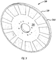
- Figure 3 shows a rotor arrangement 100 of a second embodiment that is made up of a rotor disc 110 and a series of magnets 120.
- the assembled arrangement 100 is similar in size and shape to that of the first embodiment described with reference to Figure 1 and Figure 2 . Indeed, it is envisaged that the arrangement of the second embodiment is an alternative to that of the first embodiment and may be substituted therefor in an electrical machine.
- the rotor disc 110 of this second embodiment is similar to that of the first embodiment in being formed of the same composite material and having a central aperture 112 together with a series of holes therearound 115.
- the rotor disc 110 is also similar in having twelve apertures 120 therethrough that are arranged adjacent the radially-outer edge of the rotor 110.
- the twelve apertures 120 in the rotor 110 of this embodiment are, again, similarly shaped to those of the first embodiment, but differ in certain important respects
- the rotor disc 110 of this embodiment differs, however, in that it is formed of two rotor portions 130, 140.
- Each of the two portions 130, 140 is a flat disc that fits together with the other axially: it is as if a single disc has been sliced in two to give two similar, but thinner, discs.
- FIG 4 shows a first one of the rotor portions 130 in more detail.
- each of the twelve apertures 120 that is adjacent the radially outer edge of the rotor portion 130 is shaped generally like a segment from a flattened, planar, ring: that is, each segment has radially outer 121 and inner 122 sidewalls that are arcuate and concentric, with radial sidewalls 123 extending therebetween.
- An arcuate recess 124 is provided at each end of each of the radial sidewalls 123.
- the apertures are formed by milling, these recesses are to accommodate right-angled edges of the magnets (not shown in Figure 4 ).
- each of the sidewalls 121, 122, 123 projects slightly into the aperture 120 where the sidewalls 121, 122, 123 meet the axially-outer face of the rotor portion 130 (as opposed to the face that lies against the second rotor portion 140 when the two are placed together).
- the sidewalls 121, 122, 123 project so as to form a lip 125 that is flush with the outer face of the rotor portion 120 and that extends around the opening of the aperture 120 so as to narrow that aperture 120.
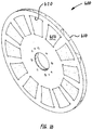
- FIG. 5 shows the second rotor portion 140 in more detail.
- the second rotor portion 140 is the similar to the first 130, but is thinner in an axial direction. It will therefore be appreciated that the second rotor portion also has a lip 145 that extends around the opening of the each aperture 120 and that is flush with the axially-outer face of the second rotor portion 140.
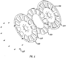
- Figure 6 shows the two rotor portions 130, 140 axially spaced apart from each other.
- the rotor arrangement 100 also includes twelve magnets 150 that are shaped as the magnets of the first embodiment.
- the magnets 150 of this embodiment are sized and shaped to fit within the apertures 120 formed in the first 130 and second 140 rotor portions.
- the magnets 150 fit within the portions such that they are abutted (with respect to the axis of rotation of the rotor) circumferentially and radially by the sidewalls 121, 122, 123 of the two rotor portions 130, 140 to locate the magnets 150 circumferentially and radially; and axially by the lips 135, 145 of the rotor portions 130, 140 when these two rotor portions 130, 140 are brought together to locate the magnets 150 axially.
- the second rotor portion 140 includes a plurality of bolt holes 147 adjacent the radially outer edge thereof.
- the first rotor portion 130 includes a plurality of corresponding holes 137 that are threaded to receive a respective bolt 160.
- the two rotor portions 130, 140 are fixed together by fitting a respective bolt 160 through each bolt hole 147 into a respective one of the threaded holes 137.
- the reason for the first rotor portion 130 being thicker than the second rotor portion 140 in the present embodiment is to allow the threaded holes 137 to be of sufficient length to retain the bolts 160.
- the relative thicknesses of the first 130 and second 140 rotor portions may differ.
- Figure 7 shows a rotor arrangement 300 of a third embodiment.
- the rotor 310 of this embodiment is formed of a first rotor portion 330 and a second rotor portion 340.
- the two rotor portions 330, 340 fit together in a radial direction, rather than an axial direction.
- Figure 8 shows the first rotor portion 330 in more detail.
- the first rotor portion is similar to that of the first embodiment, but differs in two respects.
- the first rotor portion 330 lacks the radially-outer part thereof that provides the radially-outer arcuate sidewall of each of the magnet-receiving apertures through the rotor of the first embodiment.
- the first rotor part 330 of this embodiment provides only a radially-inner arcuate sidewall 322 and two radial sidewalls 323 extending radially outwards therefrom, each with an arcuate recess 324 at the radially inner end only thereof.
- the first rotor portion 330 therefore resembles a "spider", in the engineering sense of that word.
- a projecting ridge 325 projects from the middle of each of the radially-extending sidewalls 323 and extends along the length of each of those sidewalls.
- Figure 9 shows a representative one of twelve magnets 350 of the rotor assembly 300 of this third embodiment.
- the magnet 350 is as those of the first and second embodiments but differs in having a groove 355 formed in each of the radially-extending sidewalls 352 thereof.
- Each groove 355 is formed in the middle of each of the radially-extending sidewalls 352 and runs the length thereof.
- the magnets 350 are slotted into the apertures through the first rotor portion 330, with each projecting ridge 325 of the first rotor portion 330 fitting into a respective groove.
- Adhesive tape reinforced with wire is then wound repeatedly around the radially outer edge of the first rotor portion 330 to form the second rotor portion 340.
- the first rotor portion 330 and the second rotor portion cooperate to locate the magnets 350 radially.
- Circumferential and axial location is provided by the first rotor portion 330, with the projecting ridges 325 of the first rotor portion 330 and cooperating grooves 355 in the magnets providing the axial location by virtue of a tongue-and-groove type arrangement.
- the second rotor portion 340 could be a ring of composite material formed by laying-up appropriate material on a forming mandrel. The ring would then be fitted to the outside of the first rotor portion 330 and glued in place. It is envisaged that the ring could be shrink-fitted to the outside of the first rotor portion 330 by heating the ring such that it can be fitted and then allowing it to cool into a tight fit around the first rotor portion 330. When heated, the ring may or may not be an interference fit. Alternatively, the ring could be press-fitted to the outside of the first rotor portion 330 without first heating the ring.
- FIG 10 shows a rotor arrangement 400 of a fourth embodiment.
- the rotor 410 is formed as a single portion, but there are two magnets 450 in each magnet-receiving aperture therethrough 420.
- the general arrangement is shown in Figure 11 , with more detail being shown in Figure 12 and Figure 13 .
- the rotor 410 of this embodiment is generally the same that the first rotor portion 130 of the second embodiment, but differs in lacking the lip 150 of that first rotor portion 130 and instead including projecting ridges 425 along the radially-extending sidewalls 423 of the apertures 420 through the rotor 410.
- the ridges 425 extend along the middle of the radially-extending sidewalls 423, between ends thereof, and thus are similar to those 325 of the third embodiment.
- each magnet 450 of the rotor arrangement 400 of this embodiment is geometrically the same as the other.
- Each magnet 450 is shaped generally as the magnets of the first and second embodiments, but differs in being slightly less that half the thickness (in an axial direction) and having a recess 455 formed along each radially-extending edge of one face only.
- the magnets 450 are geometrically the same, each of the two magnets 450 that is received in the same aperture 420 is magnetised differently.
- One of the magnets 450 is magnetised such that the face along which the recesses 455 extend is a North-seeking pole.
- the other of the magnets 450 is magnetised such that the face along with the recesses 455 extend is a South-seeking pole.
- two differently-magnetised magnets 450 are fitted into each aperture 420 in the rotor 410.
- a first one of the two magnets 450 is introduced into the aperture 420 from one side of the rotor 410 such that the projecting ridge 425 fits into the recess to locate the portion 450.
- the other magnet 450 is fitted in the same way from the other side of the rotor 410.
- magnetic attraction between the magnets 450 holds the magnets in place.
- the arrangement is such that there is a small axial gap between the two magnets 450 in each aperture.
- the magnetic attraction causes each of the two magnets 450 to abut the projecting ridge 425.
- the small axial gap would be of the order of 10 microns. It is generally preferred that any gap between the two magnets 450 be minimised in order to encourage the passage of magnetic flux between the two magnets 450.
- the rotor 410 provides radial and circumferential location of the magnets 450 and also locates each of the magnets 450 in one of the two possible axial directions.
- the dimensions of the magnets 450 and the rotor 410 would be such that the magnets 450 also abut the projecting ridge 425, but this depends on the relevant manufacturing tolerances.
- an adhesive such as glue
- glue may be provided between the two magnets 450 in the same aperture 420 such that the adhesive at least partly serves to hold the two magnets 450 together.
- An adhesive that has vibration-absorption properties such as glue that cures to become resiliently deformable, may be used in order to absorb vibrations.
- the rotor arrangements described above are for use in an electrical machine that is suited to high power applications.
- the electrical machine may be suited to use as a generator in a diesel-electric generator set in a large hybrid-vehicle such as a tram or a bus.
- the electrical machine may also be suited to use as a motor in such a vehicle for providing automotive mechanical power.
- the rotor disc arrangements described above are modified so as to be capable of use in an electrical machine that can be operated as an eddy current motor.
- the rotor discs described above would be replaced by a disc formed at least partly of an electrically conductive material. Applying a varying current to the stator winding would cause the machine to operate as an eddy current motor. Applying a constant would acts to brake the machine.
- the conductive material may be arranged to channel the current induced therein. This may be done by the provision of slots in the conductive material of the replacement rotor. The slots may be radial. In other words, the rotor could form an equivalent of the squirrel cage sometimes used in radial electrical machines.
- the magnets 450 may be "split" (that is may be made up of a plurality of magnet portions that interface one another) other than in the plane of the rotor in order to reduce eddy currents induced therein.
- the magnets may be split in a substantially axial-radial plane or may be split in a substantially axial-tangential plane.
- Each magnet may be split in this way so as to be made up of two, three or more magnet portions.
- the portions may be joined to each other by an adhesive, such as glue, that is preferably electrically insulating.
- the portions may be located relative to each other in the rotor by abutments formed in material of the rotor that serve to space the portions from each other.
Landscapes
- Engineering & Computer Science (AREA)
- Power Engineering (AREA)
- Permanent Field Magnets Of Synchronous Machinery (AREA)
- Iron Core Of Rotating Electric Machines (AREA)
- Permanent Magnet Type Synchronous Machine (AREA)
Applications Claiming Priority (2)
| Application Number | Priority Date | Filing Date | Title |
|---|---|---|---|
| GBGB0800225.5A GB0800225D0 (en) | 2008-01-07 | 2008-01-07 | A rotor for an electrical machine |
| PCT/GB2009/000032 WO2009087376A2 (en) | 2008-01-07 | 2009-01-07 | A rotor for an electrical machin |
Publications (2)
| Publication Number | Publication Date |
|---|---|
| EP2243209A2 EP2243209A2 (en) | 2010-10-27 |
| EP2243209B1 true EP2243209B1 (en) | 2017-03-15 |
Family
ID=39111212
Family Applications (1)
| Application Number | Title | Priority Date | Filing Date |
|---|---|---|---|
| EP09700730.6A Active EP2243209B1 (en) | 2008-01-07 | 2009-01-07 | A rotor for an electrical machin |
Country Status (6)
| Country | Link |
|---|---|
| US (1) | US8624456B2 (enExample) |
| EP (1) | EP2243209B1 (enExample) |
| JP (1) | JP2011509064A (enExample) |
| CN (1) | CN101919140B (enExample) |
| GB (2) | GB0800225D0 (enExample) |
| WO (1) | WO2009087376A2 (enExample) |
Families Citing this family (44)
| Publication number | Priority date | Publication date | Assignee | Title |
|---|---|---|---|---|
| ITMO20110252A1 (it) * | 2011-09-30 | 2013-03-31 | Montanari Giulio & C S R L | Rotore a magneti permanenti per macchina elettrica rotativa |
| JP2013162677A (ja) * | 2012-02-07 | 2013-08-19 | Denso Corp | アキシャルギャップ型回転電機および車輪 |
| FR2996377B1 (fr) * | 2012-10-03 | 2016-07-22 | Renault Sas | Rotor pour machine electrique |
| DE202012012228U1 (de) | 2012-12-20 | 2013-02-01 | Klaus-Dieter Nies | Rotor für eine Maschinenwelle einer Elektrischen Axialflussmaschine |
| GB2511320A (en) * | 2013-02-27 | 2014-09-03 | Yasa Motors Ltd | Axial flux motor |
| DE202013006718U1 (de) | 2013-07-26 | 2013-08-20 | Klaus-Dieter Nies | Rotor für eine Maschinenwelle einer elektrischen Axialflussmaschine |
| JP6255231B2 (ja) * | 2013-12-11 | 2017-12-27 | 株式会社ダイナックス | アキシャルギャップモータ |
| EP3271998A4 (en) * | 2014-03-21 | 2018-12-05 | Evans Electric Pty Limited | Rotor for an electrical machine |
| JP6137019B2 (ja) * | 2014-03-28 | 2017-05-31 | マツダ株式会社 | アキシャルギャップ型回転電機 |
| DE102015208281A1 (de) | 2015-05-05 | 2016-11-10 | Robert Bosch Gmbh | Rotor für Axialflussmaschine |
| DE102015220124A1 (de) | 2015-10-15 | 2017-04-20 | Robert Bosch Gmbh | Rotor für Scheibenläufermaschine |
| CN109314436B (zh) * | 2016-04-13 | 2020-10-27 | 詹尼斯机器人移动技术加拿大公司 | 包括径向内推力轴承和径向外推力轴承的轴向通量电机 |
| DE102016214760B4 (de) | 2016-04-28 | 2018-03-01 | Mtu Friedrichshafen Gmbh | Verfahren zum Betrieb einer Brennkraftmaschine, Einrichtung zum Steuern und/oder Regeln einer Brennkraftmaschine, Einspritzsystem und Brennkraftmaschine |
| JP6700596B2 (ja) | 2016-06-21 | 2020-05-27 | 株式会社デンソー | アキシャルギャップモータ用ロータ及びアキシャルギャップモータ |
| FR3064423B1 (fr) * | 2017-03-22 | 2019-11-15 | Whylot Sas | Rotor pour moteur ou generatrice electromagnetique a structure alveolaire comportant des alveoles pour le logement d'aimants respectifs |
| PL233865B1 (pl) * | 2017-07-28 | 2019-12-31 | Equelo Spolka Z Ograniczona Odpowiedzialnoscia | Maszyna elektryczna |
| CN107492962A (zh) * | 2017-08-31 | 2017-12-19 | 杭州中豪电动科技股份有限公司 | 一种盘式电机的磁钢固定结构 |
| CN107482813A (zh) * | 2017-10-10 | 2017-12-15 | 武汉索特南洋电机有限公司 | 盘式电机转子结构及盘式电机 |
| JP2019161723A (ja) * | 2018-03-08 | 2019-09-19 | 株式会社日立産機システム | アキシャルギャップ型回転電機 |
| DE102018210164B3 (de) * | 2018-06-22 | 2019-09-26 | Hs Products Engineering Gmbh | Verfahren zur Herstellung eines Läufers für einen Elektroflachmotor, Läufer und Elektroflachmotor |
| CN108808921B (zh) * | 2018-08-31 | 2024-02-27 | 上海盘毂动力科技股份有限公司 | 一种盘式转子及盘式电机 |
| FR3086465B1 (fr) * | 2018-09-24 | 2021-05-21 | Whylot Sas | Rotor pour moteur ou generatrice electromagnetique avec corps de moyeu et branches en couches de composite avec fibres d'orientations differentes |
| US10892654B2 (en) * | 2018-11-09 | 2021-01-12 | Shenzhen Shanxiang Intelligent Technology Enterprise | Axial magnetic field motor with grain-oriented silicon steel sheets |
| CN109639005A (zh) * | 2019-01-25 | 2019-04-16 | 三门峡速达交通节能科技股份有限公司 | 车辆、盘式电机的转子及盘式电机 |
| CN110350747A (zh) * | 2019-03-08 | 2019-10-18 | 贵州航天林泉电机有限公司 | 一种轴向磁通电机转子结构 |
| JP7212587B2 (ja) * | 2019-06-20 | 2023-01-25 | 株式会社日立産機システム | アキシャルギャップ型回転電機 |
| DE102019124185A1 (de) * | 2019-09-10 | 2021-03-11 | Schaeffler Technologies AG & Co. KG | Elektromotor, Rotor und Verfahren zur Magnetbefestigung in einem Rotor |
| CN110707845A (zh) * | 2019-09-18 | 2020-01-17 | 广州通达汽车电气股份有限公司 | 转子结构及电机 |
| EP3832860A1 (en) | 2019-12-05 | 2021-06-09 | Phi-Power AG | Single sided axial flux electrical machine with additional passive stator |
| CN111211630B (zh) * | 2020-01-21 | 2021-02-19 | 杭州中豪电动科技有限公司 | 盘式电机转子 |
| CN111181337B (zh) * | 2020-02-26 | 2021-12-21 | 安徽美芝精密制造有限公司 | 转子总成及其装配方法、电机和电动车辆 |
| FR3107999B1 (fr) | 2020-03-06 | 2023-06-23 | Renault Sas | Rotor pour machine électromagnétique à flux axial |
| FR3112907B1 (fr) | 2020-07-27 | 2025-02-14 | Conseil & Technique | Rotor à structure composite pour machine électrique à flux axial |
| CN112018916B (zh) * | 2020-08-24 | 2021-06-25 | 上海盘毂动力科技股份有限公司 | 盘式电机的转子结构 |
| JP7667317B2 (ja) * | 2021-02-08 | 2025-04-22 | マグエレック プロパルション リミテッド | アキシアルフラックスモータ用ロータ及び製造方法 |
| FR3121295B1 (fr) * | 2021-03-24 | 2023-09-01 | Renault Sas | rotor pour machine électrique à flux axial, des procédés d’assemblage et de démontage d’un tel rotor |
| WO2022252046A1 (zh) * | 2021-05-31 | 2022-12-08 | 华为数字能源技术有限公司 | 一种电机转子、驱动电机和电动汽车 |
| CN113300515B (zh) * | 2021-06-11 | 2022-11-15 | 山东大学 | 包含切向磁体结构的盘式轴向磁场永磁无刷电机结构及其方法 |
| CN118613378A (zh) | 2021-12-03 | 2024-09-06 | 奥美尼传动系统技术有限责任公司 | 双速变速箱 |
| CN115664075A (zh) * | 2022-03-30 | 2023-01-31 | 湖州龙浩汽车零部件有限公司 | 一种新能源驱动电机转子结构 |
| DE102023113760A1 (de) * | 2023-05-25 | 2024-11-28 | Schaeffler Technologies AG & Co. KG | Rotor |
| EP4485754A1 (de) * | 2023-06-27 | 2025-01-01 | dormakaba Deutschland GmbH | Permanentmagnetanordnung, axialflussmaschine und elektromechanischer antrieb |
| WO2025205839A1 (ja) * | 2024-03-26 | 2025-10-02 | ニデック株式会社 | モータ |
| WO2025208125A1 (en) * | 2024-03-29 | 2025-10-02 | Conifer Systems, Inc. | Rotor design for high-speed applications using segmented magnets |
Family Cites Families (22)
| Publication number | Priority date | Publication date | Assignee | Title |
|---|---|---|---|---|
| US3909645A (en) * | 1974-07-10 | 1975-09-30 | Singer Co | Permanent magnet motor-tachometer having a single non-ferrous armature wound with two mutually-insulated windings each connected to a separate commutator |
| FR2279246A1 (fr) | 1974-07-19 | 1976-02-13 | Cem Comp Electro Mec | Perfectionnements a la construction de machines electriques tournantes |
| US4104552A (en) * | 1976-03-04 | 1978-08-01 | Merkle-Korff Gear Co. | Synchronous motor structure |
| IT1198556B (it) * | 1983-04-15 | 1988-12-21 | Giampiero Tassinario | Motore a corrente continua senza collettore a commutazione elettronica |
| US4587450A (en) * | 1984-01-06 | 1986-05-06 | Sanyei Corporation | Synchronous motor rotor |
| US4588914A (en) * | 1984-06-05 | 1986-05-13 | Westinghouse Electric Corp. | Permanent magnet rotor for high speed motors and generators |
| JPS6260451A (ja) | 1985-09-06 | 1987-03-17 | Nissan Motor Co Ltd | 永久磁石界磁デイスク型同期機 |
| JPS62213540A (ja) | 1986-03-14 | 1987-09-19 | Nissan Motor Co Ltd | 交流発電機 |
| JPH0349545A (ja) | 1989-07-17 | 1991-03-04 | Toyota Motor Corp | 永久磁石形同期モータ |
| US5063318A (en) * | 1989-08-25 | 1991-11-05 | Sundstrand Corporation | Preloaded permanent magnet rotor assembly |
| US4996457A (en) * | 1990-03-28 | 1991-02-26 | The United States Of America As Represented By The United States Department Of Energy | Ultra-high speed permanent magnet axial gap alternator with multiple stators |
| GB2275371A (en) | 1993-02-11 | 1994-08-24 | Westcombe International Limite | An electronically commutated electric motor |
| JPH07203645A (ja) * | 1993-12-30 | 1995-08-04 | Mabuchi Motor Co Ltd | 小型モータ及びその回転子の製造方法 |
| KR0160930B1 (ko) | 1996-01-06 | 1998-12-01 | 유환덕 | 전속도 무단변속기 |
| US6373162B1 (en) * | 1999-11-11 | 2002-04-16 | Ford Global Technologies, Inc. | Permanent magnet electric machine with flux control |
| JP4193685B2 (ja) * | 2003-12-15 | 2008-12-10 | 日産自動車株式会社 | アキシャルギャップモータ構造 |
| CN1314184C (zh) * | 2004-04-19 | 2007-05-02 | 台达电子工业股份有限公司 | 马达 |
| US7586232B2 (en) * | 2005-04-26 | 2009-09-08 | Industrial Design Laboratories, Inc | Flat radially interacting electric drive and a method of the manufacturing the same |
| JP2007037210A (ja) | 2005-07-22 | 2007-02-08 | Nissan Motor Co Ltd | 回転電機の回転子 |
| JP5277514B2 (ja) * | 2005-12-15 | 2013-08-28 | 日産自動車株式会社 | 回転電機の磁石付き回転子コアの製造方法 |
| JP4169055B2 (ja) | 2006-07-14 | 2008-10-22 | ダイキン工業株式会社 | 回転電機 |
| US8598761B2 (en) | 2007-05-03 | 2013-12-03 | In Motion Technologies Pty., Ltd. | Rotor magnet positioning device |
-
2008
- 2008-01-07 GB GBGB0800225.5A patent/GB0800225D0/en not_active Ceased
-
2009
- 2009-01-07 US US12/811,979 patent/US8624456B2/en active Active
- 2009-01-07 JP JP2010541100A patent/JP2011509064A/ja active Pending
- 2009-01-07 WO PCT/GB2009/000032 patent/WO2009087376A2/en not_active Ceased
- 2009-01-07 GB GB0900202A patent/GB2456067B/en active Active
- 2009-01-07 EP EP09700730.6A patent/EP2243209B1/en active Active
- 2009-01-07 CN CN200980102183.5A patent/CN101919140B/zh active Active
Non-Patent Citations (1)
| Title |
|---|
| None * |
Also Published As
| Publication number | Publication date |
|---|---|
| US8624456B2 (en) | 2014-01-07 |
| GB0800225D0 (en) | 2008-02-13 |
| JP2011509064A (ja) | 2011-03-17 |
| CN101919140B (zh) | 2013-02-13 |
| WO2009087376A3 (en) | 2010-02-11 |
| US20110006631A1 (en) | 2011-01-13 |
| WO2009087376A2 (en) | 2009-07-16 |
| EP2243209A2 (en) | 2010-10-27 |
| GB0900202D0 (en) | 2009-02-11 |
| GB2456067B (en) | 2011-05-11 |
| GB2456067A (en) | 2009-07-08 |
| CN101919140A (zh) | 2010-12-15 |
Similar Documents
| Publication | Publication Date | Title |
|---|---|---|
| EP2243209B1 (en) | A rotor for an electrical machin | |
| US8022593B2 (en) | Electrical machine | |
| CN107465321B (zh) | 用于车辆的绕线转子同步电动机 | |
| US7834512B2 (en) | Automotive alternator including annular core having protrusions and recesses alternately formed on its outer surface | |
| US7906883B2 (en) | Axial gap motor | |
| US10148145B2 (en) | Rotor structure of wound rotor driving motor | |
| US12362614B2 (en) | Rotor for an axial flux motor | |
| CN101809846A (zh) | 轴向间隙型电动机 | |
| WO2011045860A1 (ja) | 回転電機の冷却構造 | |
| CN107925289A (zh) | 定子线圈、配备定子线圈的定子、以及配备定子的旋转电机 | |
| US20240120784A1 (en) | Rotor, motor, powertrain, and vehicle | |
| CN108092465B (zh) | 电机的旋转变压器的安装结构 | |
| CN109904941A (zh) | 用于车辆的驱动电动机 | |
| KR101930090B1 (ko) | 차량용 모터 | |
| CN104734444A (zh) | 用于驱动马达的转子固定单元 | |
| US12301060B2 (en) | Rotors for electric motors | |
| JP2021100333A (ja) | 電動機およびこの電動機を備えた車両用動力装置、発電機およびこの発電機を備えた発電機付車輪用軸受 | |
| CN119968763A (zh) | 转子、用于生产转子的制造组件、用于生产转子的方法以及电机 | |
| KR20160051580A (ko) | 영구자석 모터 | |
| CN117121348A (zh) | 电机 | |
| CN116707174A (zh) | 包括带有smc部件和具有锁定机构的层压部件的混合定子芯的轴向磁通电机 | |
| US12597816B2 (en) | Rotor, permanent magnet motor and powertrain | |
| US20250088047A1 (en) | Electrical machine | |
| US11901771B2 (en) | Rotating electric machine | |
| CN120226240A (zh) | 电动轴向通量型机器 |
Legal Events
| Date | Code | Title | Description |
|---|---|---|---|
| PUAI | Public reference made under article 153(3) epc to a published international application that has entered the european phase |
Free format text: ORIGINAL CODE: 0009012 |
|
| 17P | Request for examination filed |
Effective date: 20100806 |
|
| AK | Designated contracting states |
Kind code of ref document: A2 Designated state(s): AT BE BG CH CY CZ DE DK EE ES FI FR GB GR HR HU IE IS IT LI LT LU LV MC MK MT NL NO PL PT RO SE SI SK TR |
|
| AX | Request for extension of the european patent |
Extension state: AL BA RS |
|
| DAX | Request for extension of the european patent (deleted) | ||
| 17Q | First examination report despatched |
Effective date: 20151208 |
|
| RAP1 | Party data changed (applicant data changed or rights of an application transferred) |
Owner name: GKN EVO EDRIVE SYSTEMS LIMITED |
|
| GRAP | Despatch of communication of intention to grant a patent |
Free format text: ORIGINAL CODE: EPIDOSNIGR1 |
|
| INTG | Intention to grant announced |
Effective date: 20160923 |
|
| GRAS | Grant fee paid |
Free format text: ORIGINAL CODE: EPIDOSNIGR3 |
|
| GRAA | (expected) grant |
Free format text: ORIGINAL CODE: 0009210 |
|
| AK | Designated contracting states |
Kind code of ref document: B1 Designated state(s): AT BE BG CH CY CZ DE DK EE ES FI FR GB GR HR HU IE IS IT LI LT LU LV MC MK MT NL NO PL PT RO SE SI SK TR |
|
| REG | Reference to a national code |
Ref country code: CH Ref legal event code: EP Ref country code: GB Ref legal event code: FG4D |
|
| REG | Reference to a national code |
Ref country code: IE Ref legal event code: FG4D |
|
| REG | Reference to a national code |
Ref country code: AT Ref legal event code: REF Ref document number: 876470 Country of ref document: AT Kind code of ref document: T Effective date: 20170415 |
|
| REG | Reference to a national code |
Ref country code: DE Ref legal event code: R096 Ref document number: 602009044732 Country of ref document: DE |
|
| REG | Reference to a national code |
Ref country code: NL Ref legal event code: MP Effective date: 20170315 |
|
| REG | Reference to a national code |
Ref country code: LT Ref legal event code: MG4D |
|
| PG25 | Lapsed in a contracting state [announced via postgrant information from national office to epo] |
Ref country code: FI Free format text: LAPSE BECAUSE OF FAILURE TO SUBMIT A TRANSLATION OF THE DESCRIPTION OR TO PAY THE FEE WITHIN THE PRESCRIBED TIME-LIMIT Effective date: 20170315 Ref country code: HR Free format text: LAPSE BECAUSE OF FAILURE TO SUBMIT A TRANSLATION OF THE DESCRIPTION OR TO PAY THE FEE WITHIN THE PRESCRIBED TIME-LIMIT Effective date: 20170315 Ref country code: GR Free format text: LAPSE BECAUSE OF FAILURE TO SUBMIT A TRANSLATION OF THE DESCRIPTION OR TO PAY THE FEE WITHIN THE PRESCRIBED TIME-LIMIT Effective date: 20170616 Ref country code: NO Free format text: LAPSE BECAUSE OF FAILURE TO SUBMIT A TRANSLATION OF THE DESCRIPTION OR TO PAY THE FEE WITHIN THE PRESCRIBED TIME-LIMIT Effective date: 20170615 Ref country code: LT Free format text: LAPSE BECAUSE OF FAILURE TO SUBMIT A TRANSLATION OF THE DESCRIPTION OR TO PAY THE FEE WITHIN THE PRESCRIBED TIME-LIMIT Effective date: 20170315 |
|
| REG | Reference to a national code |
Ref country code: AT Ref legal event code: MK05 Ref document number: 876470 Country of ref document: AT Kind code of ref document: T Effective date: 20170315 |
|
| PG25 | Lapsed in a contracting state [announced via postgrant information from national office to epo] |
Ref country code: BG Free format text: LAPSE BECAUSE OF FAILURE TO SUBMIT A TRANSLATION OF THE DESCRIPTION OR TO PAY THE FEE WITHIN THE PRESCRIBED TIME-LIMIT Effective date: 20170615 Ref country code: SE Free format text: LAPSE BECAUSE OF FAILURE TO SUBMIT A TRANSLATION OF THE DESCRIPTION OR TO PAY THE FEE WITHIN THE PRESCRIBED TIME-LIMIT Effective date: 20170315 Ref country code: LV Free format text: LAPSE BECAUSE OF FAILURE TO SUBMIT A TRANSLATION OF THE DESCRIPTION OR TO PAY THE FEE WITHIN THE PRESCRIBED TIME-LIMIT Effective date: 20170315 |
|
| PG25 | Lapsed in a contracting state [announced via postgrant information from national office to epo] |
Ref country code: NL Free format text: LAPSE BECAUSE OF FAILURE TO SUBMIT A TRANSLATION OF THE DESCRIPTION OR TO PAY THE FEE WITHIN THE PRESCRIBED TIME-LIMIT Effective date: 20170315 |
|
| PG25 | Lapsed in a contracting state [announced via postgrant information from national office to epo] |
Ref country code: CZ Free format text: LAPSE BECAUSE OF FAILURE TO SUBMIT A TRANSLATION OF THE DESCRIPTION OR TO PAY THE FEE WITHIN THE PRESCRIBED TIME-LIMIT Effective date: 20170315 Ref country code: AT Free format text: LAPSE BECAUSE OF FAILURE TO SUBMIT A TRANSLATION OF THE DESCRIPTION OR TO PAY THE FEE WITHIN THE PRESCRIBED TIME-LIMIT Effective date: 20170315 Ref country code: RO Free format text: LAPSE BECAUSE OF FAILURE TO SUBMIT A TRANSLATION OF THE DESCRIPTION OR TO PAY THE FEE WITHIN THE PRESCRIBED TIME-LIMIT Effective date: 20170315 Ref country code: SK Free format text: LAPSE BECAUSE OF FAILURE TO SUBMIT A TRANSLATION OF THE DESCRIPTION OR TO PAY THE FEE WITHIN THE PRESCRIBED TIME-LIMIT Effective date: 20170315 Ref country code: ES Free format text: LAPSE BECAUSE OF FAILURE TO SUBMIT A TRANSLATION OF THE DESCRIPTION OR TO PAY THE FEE WITHIN THE PRESCRIBED TIME-LIMIT Effective date: 20170315 Ref country code: EE Free format text: LAPSE BECAUSE OF FAILURE TO SUBMIT A TRANSLATION OF THE DESCRIPTION OR TO PAY THE FEE WITHIN THE PRESCRIBED TIME-LIMIT Effective date: 20170315 |
|
| PG25 | Lapsed in a contracting state [announced via postgrant information from national office to epo] |
Ref country code: IS Free format text: LAPSE BECAUSE OF FAILURE TO SUBMIT A TRANSLATION OF THE DESCRIPTION OR TO PAY THE FEE WITHIN THE PRESCRIBED TIME-LIMIT Effective date: 20170715 Ref country code: PT Free format text: LAPSE BECAUSE OF FAILURE TO SUBMIT A TRANSLATION OF THE DESCRIPTION OR TO PAY THE FEE WITHIN THE PRESCRIBED TIME-LIMIT Effective date: 20170717 Ref country code: PL Free format text: LAPSE BECAUSE OF FAILURE TO SUBMIT A TRANSLATION OF THE DESCRIPTION OR TO PAY THE FEE WITHIN THE PRESCRIBED TIME-LIMIT Effective date: 20170315 |
|
| REG | Reference to a national code |
Ref country code: DE Ref legal event code: R097 Ref document number: 602009044732 Country of ref document: DE |
|
| REG | Reference to a national code |
Ref country code: FR Ref legal event code: PLFP Year of fee payment: 10 |
|
| PLBE | No opposition filed within time limit |
Free format text: ORIGINAL CODE: 0009261 |
|
| STAA | Information on the status of an ep patent application or granted ep patent |
Free format text: STATUS: NO OPPOSITION FILED WITHIN TIME LIMIT |
|
| PG25 | Lapsed in a contracting state [announced via postgrant information from national office to epo] |
Ref country code: DK Free format text: LAPSE BECAUSE OF FAILURE TO SUBMIT A TRANSLATION OF THE DESCRIPTION OR TO PAY THE FEE WITHIN THE PRESCRIBED TIME-LIMIT Effective date: 20170315 |
|
| 26N | No opposition filed |
Effective date: 20171218 |
|
| PG25 | Lapsed in a contracting state [announced via postgrant information from national office to epo] |
Ref country code: SI Free format text: LAPSE BECAUSE OF FAILURE TO SUBMIT A TRANSLATION OF THE DESCRIPTION OR TO PAY THE FEE WITHIN THE PRESCRIBED TIME-LIMIT Effective date: 20170315 |
|
| REG | Reference to a national code |
Ref country code: CH Ref legal event code: PL |
|
| PG25 | Lapsed in a contracting state [announced via postgrant information from national office to epo] |
Ref country code: LU Free format text: LAPSE BECAUSE OF NON-PAYMENT OF DUE FEES Effective date: 20180107 |
|
| REG | Reference to a national code |
Ref country code: IE Ref legal event code: MM4A |
|
| REG | Reference to a national code |
Ref country code: BE Ref legal event code: MM Effective date: 20180131 |
|
| PG25 | Lapsed in a contracting state [announced via postgrant information from national office to epo] |
Ref country code: CH Free format text: LAPSE BECAUSE OF NON-PAYMENT OF DUE FEES Effective date: 20180131 Ref country code: BE Free format text: LAPSE BECAUSE OF NON-PAYMENT OF DUE FEES Effective date: 20180131 Ref country code: LI Free format text: LAPSE BECAUSE OF NON-PAYMENT OF DUE FEES Effective date: 20180131 |
|
| PG25 | Lapsed in a contracting state [announced via postgrant information from national office to epo] |
Ref country code: IE Free format text: LAPSE BECAUSE OF NON-PAYMENT OF DUE FEES Effective date: 20180107 |
|
| PG25 | Lapsed in a contracting state [announced via postgrant information from national office to epo] |
Ref country code: MC Free format text: LAPSE BECAUSE OF FAILURE TO SUBMIT A TRANSLATION OF THE DESCRIPTION OR TO PAY THE FEE WITHIN THE PRESCRIBED TIME-LIMIT Effective date: 20170315 |
|
| PG25 | Lapsed in a contracting state [announced via postgrant information from national office to epo] |
Ref country code: MT Free format text: LAPSE BECAUSE OF NON-PAYMENT OF DUE FEES Effective date: 20180107 |
|
| PG25 | Lapsed in a contracting state [announced via postgrant information from national office to epo] |
Ref country code: TR Free format text: LAPSE BECAUSE OF FAILURE TO SUBMIT A TRANSLATION OF THE DESCRIPTION OR TO PAY THE FEE WITHIN THE PRESCRIBED TIME-LIMIT Effective date: 20170315 |
|
| PG25 | Lapsed in a contracting state [announced via postgrant information from national office to epo] |
Ref country code: HU Free format text: LAPSE BECAUSE OF FAILURE TO SUBMIT A TRANSLATION OF THE DESCRIPTION OR TO PAY THE FEE WITHIN THE PRESCRIBED TIME-LIMIT; INVALID AB INITIO Effective date: 20090107 |
|
| PG25 | Lapsed in a contracting state [announced via postgrant information from national office to epo] |
Ref country code: MK Free format text: LAPSE BECAUSE OF NON-PAYMENT OF DUE FEES Effective date: 20170315 Ref country code: CY Free format text: LAPSE BECAUSE OF FAILURE TO SUBMIT A TRANSLATION OF THE DESCRIPTION OR TO PAY THE FEE WITHIN THE PRESCRIBED TIME-LIMIT Effective date: 20170315 |
|
| REG | Reference to a national code |
Ref country code: FR Ref legal event code: PLFP Year of fee payment: 15 |
|
| PGFP | Annual fee paid to national office [announced via postgrant information from national office to epo] |
Ref country code: GB Payment date: 20260122 Year of fee payment: 18 |
|
| PGFP | Annual fee paid to national office [announced via postgrant information from national office to epo] |
Ref country code: DE Payment date: 20260120 Year of fee payment: 18 |
|
| PGFP | Annual fee paid to national office [announced via postgrant information from national office to epo] |
Ref country code: IT Payment date: 20260130 Year of fee payment: 18 |
|
| PGFP | Annual fee paid to national office [announced via postgrant information from national office to epo] |
Ref country code: FR Payment date: 20260123 Year of fee payment: 18 |