EP2241421A1 - Dispositif pour portionner des aliments - Google Patents
Dispositif pour portionner des aliments Download PDFInfo
- Publication number
- EP2241421A1 EP2241421A1 EP20100006821 EP10006821A EP2241421A1 EP 2241421 A1 EP2241421 A1 EP 2241421A1 EP 20100006821 EP20100006821 EP 20100006821 EP 10006821 A EP10006821 A EP 10006821A EP 2241421 A1 EP2241421 A1 EP 2241421A1
- Authority
- EP
- European Patent Office
- Prior art keywords
- portioning
- chamber
- press
- plate
- pressing
- Prior art date
- Legal status (The legal status is an assumption and is not a legal conclusion. Google has not performed a legal analysis and makes no representation as to the accuracy of the status listed.)
- Granted
Links
Images


Classifications
-
- B—PERFORMING OPERATIONS; TRANSPORTING
- B26—HAND CUTTING TOOLS; CUTTING; SEVERING
- B26D—CUTTING; DETAILS COMMON TO MACHINES FOR PERFORATING, PUNCHING, CUTTING-OUT, STAMPING-OUT OR SEVERING
- B26D7/00—Details of apparatus for cutting, cutting-out, stamping-out, punching, perforating, or severing by means other than cutting
- B26D7/01—Means for holding or positioning work
- B26D7/02—Means for holding or positioning work with clamping means
-
- B—PERFORMING OPERATIONS; TRANSPORTING
- B26—HAND CUTTING TOOLS; CUTTING; SEVERING
- B26D—CUTTING; DETAILS COMMON TO MACHINES FOR PERFORATING, PUNCHING, CUTTING-OUT, STAMPING-OUT OR SEVERING
- B26D2210/00—Machines or methods used for cutting special materials
- B26D2210/02—Machines or methods used for cutting special materials for cutting food products, e.g. food slicers
- B26D2210/04—Machines or methods used for cutting special materials for cutting food products, e.g. food slicers controlling the volume by pressing the food product, e.g. meat to a predetermined shape before cutting
-
- B—PERFORMING OPERATIONS; TRANSPORTING
- B26—HAND CUTTING TOOLS; CUTTING; SEVERING
- B26D—CUTTING; DETAILS COMMON TO MACHINES FOR PERFORATING, PUNCHING, CUTTING-OUT, STAMPING-OUT OR SEVERING
- B26D7/00—Details of apparatus for cutting, cutting-out, stamping-out, punching, perforating, or severing by means other than cutting
- B26D7/18—Means for removing cut-out material or waste
- B26D7/1818—Means for removing cut-out material or waste by pushing out
-
- Y—GENERAL TAGGING OF NEW TECHNOLOGICAL DEVELOPMENTS; GENERAL TAGGING OF CROSS-SECTIONAL TECHNOLOGIES SPANNING OVER SEVERAL SECTIONS OF THE IPC; TECHNICAL SUBJECTS COVERED BY FORMER USPC CROSS-REFERENCE ART COLLECTIONS [XRACs] AND DIGESTS
- Y10—TECHNICAL SUBJECTS COVERED BY FORMER USPC
- Y10T—TECHNICAL SUBJECTS COVERED BY FORMER US CLASSIFICATION
- Y10T83/00—Cutting
- Y10T83/202—With product handling means
- Y10T83/2066—By fluid current
- Y10T83/207—By suction means
Definitions
- the invention relates to a device for portioning food, in particular meat.
- Such devices are used to cut food into portions, for example in the form of slices, the same weight and / or thickness.
- the foods include, for example, fresh meat, sausage, ham, cheese, vegetables or baked goods.
- Known devices for slicing sausage or cheese are also referred to as slicers. Sausage or cheese differs from freshly grown meat because of its consistency in that the corresponding loaves have a solid shape with a volume determined by the production.
- the slicers are therefore equipped with a device for holding the loaves during slicing of the slices.
- pieces of fresh grown meat do not have a solid shape or volume, unless frozen or frozen. For portioning such pieces of meat it is therefore not enough to keep the pieces of meat as in known slicers.
- Portioning devices therefore have a pressing chamber in which the piece of meat is first compressed. After completion of the pressing process, the volume which fills the piece of meat is known. This is used during the subsequent portioning.
- Portioning devices for freshly grown meat are used, for example, in commercial kitchens, in the production of compiled and pre-packaged menus and machine packaging of sliced foods. From a piece of fresh, aged meat or another piece of food individual portions, especially quick pieces of meat, such as schnitzel, steaks or medallions are separated. It is important that the individual portions have a predetermined weight and optionally a predetermined thickness. The slices must be portioned as precisely as possible so that they coincide in their cooking time, the individual portions are not too different and the weight can be stated on a preprinted pack.
- a device for portioning food with an inserting drum having a plurality of pressing chambers and a portioning drum having a plurality of portioning chambers is known.
- the piece of food is compressed in a pressing chamber by means of a side cover and a press ram and pressed into a portioning chamber.
- the portion located in the portioning chamber is separated from the piece of meat by means of a knife movable between the pressing chamber and the portioning chamber, and the portion is removed from the portioning chamber.
- the portioning drum is rotated.
- another portioning chamber of the portioning drum comes in extension of the pressing chamber.
- the other Portionierhunt can be filled again with the food. This process is repeated until the entire food is divided into portions.
- another piece of food can be placed in a second pressing chamber of the inserting drum. If the first piece of food is completely divided into portions, the loading drum is rotated. The portioning can then be continued with the second piece of food. In the now empty pressing chamber can be inserted again a piece of food.
- the slices in the known device after portioning can not be further processed automatically, for example, broken into cubes or strips or provided with a necessary for Cordonbleu Schnitzel section.
- the device according to the invention with the features of claim 1 is characterized in that an ejection element is arranged on the Portionierplatte to eject a separated disc from a Portionierhunt.
- the ejection element is arranged on that side of the portioning plate which faces away from the pressing chamber.
- the ejection element is provided at the position where the separated slices are deposited on a conveyor or in a container.
- the ejection element aids in the process of detaching a severed slice from a portioning chamber.
- a mold or trough is arranged whose cross-section coincides with the cross-section of the portioning chambers.
- a separated slices from a portioning chamber is pressed into the mold. While the portioning plate is moved to cut off another portion of one piece and to deliver another separated disc, the held in the form of disc remains in position and can optionally be further processed. It can be exploited that the portion is fixed in the mold. This is for the further processing of the portion of advantage, since the portion of the tools or tools used for processing can not escape in the form. In the form, for example, the portion can be cut and / or provided with further ingredients.
- an ejection element On the portioning plate, an ejection element is arranged which ejects one or more separated portions from the portioning chamber.
- This is, for example, a stamp that enters the portioning chamber from one side and displaces the portions from the portioning chamber. This speeds up the process of ejecting one or more portions from the portioning chamber.
- a mold On the side facing away from the ejection element of the portioning plate, a mold is arranged whose cross-section coincides with the cross-section of the portioning chambers.
- the ejection element ensures that the separated portion is transferred in the form predetermined by the Portionierhunt to an additional form.
- the further processing or processing of the portion can be done.
- the mold may be equipped with a plurality of blades for cutting cubes or strips. The portion is thus divided during ejection from the portioning chamber into further small sections. This is done in a single operation without the need for additional stations. Furthermore, during the further processing and processing of the portion, the portioning process can be continued.
- cutting tools such as knives, blades or blades are arranged in or on the form to cut the portion arranged in the form in strips or cubes or to produce an incised pocket.
- Ingredients can be filled into the portion, for example, with a schnitzel cordon butter and ham.
- the cutting tools can either be fixed or movable in or on the mold. For cutting a relative movement between the portion to be cut and the cutting tool is necessary. If the cutting tool is stationarily arranged in or on the mold, the cutting takes place when the portion is introduced into the mold and / or when the portion is removed from the mold. If the cutting tool is arranged movably on the mold, the cutting can also take place during the stay of the portion in the mold.
- the mold is equipped with a guide for the movable cutting tool. This may, for example, be a slot in the mold.
- the mold is arranged in spatial distance from the pressing unit. It does not hinder the process of portioning and slicing the individual portions.
- the deposition of the separated portions in the mold and optionally the further processing of the portion in the mold takes place only when the cutting operation is completed. At the same time as depositing a portion in the mold, another portion of the piece can be cut off at the press unit.
- the chamber bottom to adjust the depth of the portioning chamber is arranged displaceably. In this way, portions of different thickness can be produced.
- a collecting container for collecting a plurality of portions is arranged on the portioning plate on the side facing away from the pressing unit.
- the cross-section of the collecting container coincides with the cross section of the Portionierhuntn.
- the chamber bottom of the portioning chamber is displaceable in the collecting container. This allows the cutting of several portions and collection of the portions before they are ejected from the portioning chamber.
- the collection container is movable together with the portioning plate, so that both parts can be transferred together to an ejection position, while the portioning process is continued with another portioning chamber of the portioning plate.
- the chamber bottom of the portioning chamber is equipped with channels for sucking and / or expelling air or other gases.
- the device has pins whose cross-section coincides with the cross-section of the channels or is slightly smaller.
- a pin drive is provided which retracts the pins in a certain position of the portioning plate in the channels and thereby freed the channels of impurities. Such cleaning may be performed automatically after a predetermined number of servings or as needed.
- the pressing unit is vertically aligned.
- the pressing chambers extend in their longitudinal direction in the vertical direction.
- the press ram is arranged on the underside of the press unit.
- the cutting element is located at the top of the pressing unit.
- the portioning plate is arranged above the cutting element.
- This arrangement is characterized in that the press chambers can be conveniently filled from the top with a piece of food.
- the opening of the pressing chamber, accessible from above, is at a comfortable height for the user.
- the feed through the Press stamp is from bottom to top.
- the portions separated from the piece are transferred on the knife together with the Portionierhunt in an ejection position.
- the portioning chamber is released downwards.
- a top-mounted ejection element the separated portion is pressed down and falls onto a conveyor or transport device or a container in which the separated portions are collected.
- one or more transport means are arranged below the Portionierplatte to take over the separated portions and to transport.
- a round portioning plate with, for example, four portioning chambers for example, three positions for depositing a separated portion are possible in addition to the position of the actual portioning process. Each of these positions can be assigned to a separate transport device. In this way, portions can be stored on different transport devices depending on their weight or quality.
- the portioning plate is arranged rotatably about an axis. It also has an even number of Portionierhuntn, which are all arranged at the same radial distance from the axis and at the same angular distance from one another in the portioning.
- the rotatable arrangement of the portioning plate has the advantage that the portioning plate can be moved faster than in a displaceable arrangement. This leads to shorter cycle times. If all the portioning chambers in the portioning plate have the same radial distance from the axis, and if the number of portioning chambers is even, then the portioning and cutting and depositing of separated portions at different conveying devices can take place simultaneously. This increases the cycle time of the device.
- the pressing unit and the portioning plate are rotatable about two parallel, spatially separated axes.
- the rotatable arrangement ensures that the movement of the pressing unit and the portioning plate can proceed faster than with a displaceable arrangement.
- Two spatially separated axes mean that the press unit and the portioning plate do not interfere with each other in their movements, and that the ejection or removal of the separated portions from the portioning chambers of the portioning carried out at a distance from the pressing unit and thus sufficient space for the transport of separated portions is available.
- Parallel axes are advantageous because the cut is usually perpendicular to the direction of advance of the piece in the press chamber and the press chambers are arranged with their longitudinal axis parallel to the axis of the press unit.
- the pressing die and / or the chamber bottom are equipped with a force sensor.
- the force is measured, with which the piece presses against the ram to vice versa. The same applies to the chamber floor.
- This measured force is input to the servo drive control.
- the press die and / or the chamber bottom are equipped with a displacement or position sensor. While the displacement sensor measures a distance traveled by the ram or chamber bottom, the position sensor determines the absolute position of the ram or chamber bottom relative to a predetermined zero point. The value measured by the sensor is input to the servo drive control.
- FIGS. 1 and 2 a device for portioning meat is shown in two different perspective views.
- the device essentially consists of a press unit 1, a portioning plate 2 and a knife rotatably arranged between the pressing unit and the portioning plate.
- the knife is in the perspective view according to FIG. 1 and 2 not visible.
- the press unit 1 has two press chambers 3a and 3b which are delimited by a respective press chamber housing 4a and 4b and one closure element 5a and 5b each.
- the pressing chamber 3a is below the portioning plate 2 and is therefore not visible. This also applies to the closure element 5a of the pressing chamber 3a. Only the compression chamber housing 4a is partially visible.
- the press unit 1 is driven by a press unit drive for rotation.
- the pressing unit 1 occupies essentially two positions. In a first in the FIGS. 1 and 2 As shown, the first pressing chamber 3a is located below the portioning plate 2 and the second pressing chamber 3b is at the maximum distance from the portioning plate 2. In this setting, the piece of meat located in this pressing chamber 3a is divided into portions. The second pressing chamber 3b is not covered by the portioning plate 2 and therefore freely accessible from above. In it a piece of meat can be introduced from above. In order to facilitate the insertion, the closure element 5b is pulled out of the compression chamber housing 4b so far that the Cross section of the pressing chamber 3b has its largest possible initial setting.
- the closing element 5b is pushed into the pressing chamber housing 4b with the aid of a closing element drive 7 in order to reduce the cross section of the pressing chamber 3b.
- a force sensor not shown in the drawing, thereby determines the force with which the piece of meat counteracts the closure element drive 7.
- the closure element 5b is locked in position.
- the corresponding to the relevant setting of the closure element 5b cross section of the pressing chamber is determined by a, also not recognizable in the drawing displacement sensor.
- the pressing unit 1 is rotated and the second portioning chamber 3b filled with a piece of meat is moved under the portioning plate 2.
- the first pressing chamber 3a is now empty and can be refilled with a piece of meat. This is done in the same way as described above.
- the displacement of the closure elements 5 a and 5 b can take place before, during or after the rotation of the press unit 1.
- the two press chambers 3a and 3b are identical.
- a pressing ram 8 is inserted from below into the pressing chamber 3a or 3b arranged below the portioning plate 2.
- the punch can also be referred to as a plunger. He is in the FIGS. 1 and 2 not visible. He is in the FIGS. 3 to 7 and 15 shown.
- the pressing ram 8 pushes the meat from the bottom upwards into a portioning chamber 9 of the portioning plate 2 arranged above the pressing chamber 3a or 3b.
- the portioning plate 2 is equipped with a total of 4 portioning chambers 9. Above the position at which a pressing chamber 3a or 3b can be brought into coincidence with a portioning chamber 9, a chamber bottom 10 is arranged to be displaceable in the vertical direction. To the Moving the chamber bottom 10, a chamber floor drive 11 is provided.
- the chamber bottom 10 is inserted from above into a portioning chamber 9.
- the thickness and thus the weight of a portion depends on how far or how deep the bottom of the chamber protrudes into the portioning chamber.
- the weight of the portions and their thickness is thus adjustable over the position of the chamber bottom 10.
- the piece of meat is pressed from below through the press ram 8 into the portioning chamber 9 closed by the chamber bottom 10, so that the meat fills the entire portioning chamber.
- the press ram 8 and the chamber bottom 10 press against each other.
- the portion, which is located in the portioning chamber 9 is cut by a knife, not shown, from the piece of meat.
- a knife not shown
- the chamber bottom 10 is pulled upwards by the chamber bottom drive 11, so that the portioning plate 2 can be rotated by the portioning plate drive 12.
- the rotation in this case by 90 °, 180 ° or 270 °. This depends on the quality of the portion.
- End pieces of the meat piece which have a lower weight than the predetermined target weight, for example, can be separated from the remaining portions.
- the knife not visible in the drawing, is rotated together with the portioning plate 2 until the separated portion is above the intended ejection position. Subsequently, the knife is returned to its original position above the pressing chamber to cut off the next portion.
- the portioning chamber 9 is now open at the bottom. With the aid of a punch-like ejection element 13, the separated portion is pushed down out of the portioning chamber 9 and falls into a container 14, which is moved by a transport device 15.
- a second punch-like Ausforcestelement 16 is located above a second transport means 17. Both ejectors 13 and 16 are equipped with drives 18 and 19.
- the associated closing element 5a or 5b is pulled out of the pressing chamber housing 4a or 4b, so that the cross section of the pressing chamber increases again and the insertion of a piece of meat is relieved.
- the position and the force of the closure element 5a or 5b are continuously detected not only when a new piece of meat is inserted, but also during the portioning process. If the force decreases or increases due to the shape of the piece of meat during the portioning operation, the position of the closure element can be adjusted during the portioning process.
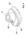
- FIGS. 3 to 7 show the press stamp in different views.
- the press stamp has a holder 20, on which a in FIG. 15 recognizable press-rod 39 can be fixed, which the movement of a in the Figures 14 and 15 recognizable press ram drive 38 transmits to the ram.
- the press ram 8 further has two ram elements 21 and 22, which are each equipped with finger-like projections 23.
- the first ram member 21 is fixedly connected to the holder 20.
- the second press-stamp element 22 is displaceable relative to the first press-stamp element.
- the second punch member 22 is this in an in FIG. 6 recognizable slot of the ram 8 out.
- the guide is also reinforced by the finger-like extensions 23, with which the two press-stamp elements 21 and 22 engage with each other.
- the finger-like extensions 23 of the two punch elements and the distances between the finger-like extensions 23 are formed identically in both punch elements 21, 22.
- the two pressing die elements 21 and 22 are covered by a plate 24.
- two pins 25 are slidably mounted. They are supported by springs, not visible in the drawing, on the second ram element 22. The springs push the two pins 25 to the outside. They ensure that without the action of an external force, the two press-stamp elements 21 and 22 in the starting position according to FIG. 4 have the greatest possible distance. Only by the action of an external force can they enter the in FIG.
- the chamber bottom 10 is shown, which is adjustable with respect to its chamber bottom surface just like the press ram.
- the structure of the chamber bottom with a holder 26, two chamber bottom elements 27 and 28, finger-like extensions 29, a plate 30 and pins 31 corresponds to the structure of the press ram.
- the functionality is identical.
- the force which presses the two chamber bottom elements 27 and 28 together is exerted on the chamber bottom 10 by the portioning chamber 9.
- the chamber bottom is additionally equipped with channels 32 and ports 33 to extract air from the portioning chamber or to introduce compressed air.
- the suction of air favors the complete filling of the portioning chamber with meat.
- the introduction of compressed air promotes the ejection of a portion from the portioning chamber.
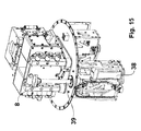
- FIG. 13 shows the portioning plate 2 with two ejection elements 13 and 16, a drive 34 for the knife, and the portioning plate drive 12 and additional molds 35 below the portioning plate 2, with which a portion can be divided into cubes.
- Each of the two molds 35 is equipped with a gate of several blades.
- the two ejection elements 13 and 16 press a portion disposed in a portioning chamber 9 down into the molds 35, whereby the portion is cut into cubes. The cubes then fall down and are sent for further processing.
- FIG. 14 shows the device in a similar view as in FIG. 1 , In contrast to FIG. 1 is the second conveyor 36 formed only half as long, the second conveyor 17 in FIG. 1 , In addition, the press unit 1 without pressing unit drive housing 6 is shown. Because of this, are in FIG. 14 the drive 37 for rotating the press unit 1 and the ram drive 38 can be seen. It is the punch drive 38 is a servo drive with an electric motor.
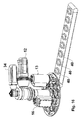
- FIG. 15 shows a section FIG. 14 , In the section, only the pressing unit 1 is shown.
- the pressing chamber housing 4b and the closing element 5b are missing, so that the pressing ram 8 with the pressing ram bar 39 can be seen.
- the press ram rod 39 transmits the stroke of the ram drive 38 to the ram 8.
- FIG. 16 shows a further embodiment of molds 40, in which a portion can be stored after cutting by the portioning and a discharge element 13.
- the molds 40 do not contain cutting tools.
Landscapes
- Life Sciences & Earth Sciences (AREA)
- Forests & Forestry (AREA)
- Engineering & Computer Science (AREA)
- Mechanical Engineering (AREA)
- Meat, Egg Or Seafood Products (AREA)
- Beans For Foods Or Fodder (AREA)
- Manufacturing And Processing Devices For Dough (AREA)
- Control And Other Processes For Unpacking Of Materials (AREA)
- General Preparation And Processing Of Foods (AREA)
- Processing Of Meat And Fish (AREA)
- Formation And Processing Of Food Products (AREA)
Applications Claiming Priority (2)
| Application Number | Priority Date | Filing Date | Title |
|---|---|---|---|
| DE102007021509 | 2007-05-04 | ||
| EP20080758005 EP2144735B1 (fr) | 2007-05-04 | 2008-05-05 | Dispositif de coupe en portions de produits alimentaires |
Related Parent Applications (1)
| Application Number | Title | Priority Date | Filing Date |
|---|---|---|---|
| EP08758005.6 Division | 2008-05-05 |
Publications (2)
| Publication Number | Publication Date |
|---|---|
| EP2241421A1 true EP2241421A1 (fr) | 2010-10-20 |
| EP2241421B1 EP2241421B1 (fr) | 2012-07-11 |
Family
ID=39766831
Family Applications (3)
| Application Number | Title | Priority Date | Filing Date |
|---|---|---|---|
| EP20100006820 Active EP2248641B1 (fr) | 2007-05-04 | 2008-05-05 | Dispositif et méthode pour portionner des aliments |
| EP20080758005 Active EP2144735B1 (fr) | 2007-05-04 | 2008-05-05 | Dispositif de coupe en portions de produits alimentaires |
| EP20100006821 Active EP2241421B1 (fr) | 2007-05-04 | 2008-05-05 | Dispositif pour portionner des aliments |
Family Applications Before (2)
| Application Number | Title | Priority Date | Filing Date |
|---|---|---|---|
| EP20100006820 Active EP2248641B1 (fr) | 2007-05-04 | 2008-05-05 | Dispositif et méthode pour portionner des aliments |
| EP20080758005 Active EP2144735B1 (fr) | 2007-05-04 | 2008-05-05 | Dispositif de coupe en portions de produits alimentaires |
Country Status (8)
| Country | Link |
|---|---|
| US (1) | US8622727B2 (fr) |
| EP (3) | EP2248641B1 (fr) |
| AT (2) | ATE546264T1 (fr) |
| DE (2) | DE502008002815D1 (fr) |
| DK (1) | DK2144735T3 (fr) |
| ES (2) | ES2381438T3 (fr) |
| PL (2) | PL2248641T3 (fr) |
| WO (1) | WO2008135025A2 (fr) |
Cited By (1)
| Publication number | Priority date | Publication date | Assignee | Title |
|---|---|---|---|---|
| EP3542979A1 (fr) * | 2018-03-19 | 2019-09-25 | TVI Entwicklung und Produktion GmbH | Procédé de pressage et, en particulier ensuite de découpe de meules élastiques, en particulier de pâtons de viande et machine de coupe correspondante |
Families Citing this family (4)
| Publication number | Priority date | Publication date | Assignee | Title |
|---|---|---|---|---|
| DE102009054081B4 (de) * | 2009-11-20 | 2012-03-22 | Thomas Völkl | Würfelschneider |
| US20130337135A1 (en) * | 2012-06-13 | 2013-12-19 | Michael F. Vieira | Apparatuses for producing food products from fish and chicken shims and associated systems and methods |
| US10849329B2 (en) * | 2016-02-08 | 2020-12-01 | Angela Marie Hotz | Hamburger press patty express |
| DE102018132899B3 (de) * | 2018-12-19 | 2020-03-26 | Martin Bergmann | Magazinrevolvereinrichtung für Portioniermaschine |
Citations (3)
| Publication number | Priority date | Publication date | Assignee | Title |
|---|---|---|---|---|
| US6383068B1 (en) * | 1998-04-09 | 2002-05-07 | Tyson Foods, Inc. | Food portioning apparatus and method |
| DE10304773A1 (de) | 2003-02-05 | 2004-08-19 | Maja-Maschinenfabrik Hermann Schill Gmbh & Co. Kg | Vorrichtung und Verfahren zum Portionieren eines Lebensmittelstücks |
| DE102004041915A1 (de) * | 2004-08-30 | 2006-03-16 | Völkl, Thomas | Vorrichtung und Verfahren zum Portionieren |
Family Cites Families (48)
| Publication number | Priority date | Publication date | Assignee | Title |
|---|---|---|---|---|
| US3687067A (en) * | 1969-11-20 | 1972-08-29 | Bettcher Industries | Food press |
| US3648600A (en) * | 1970-03-02 | 1972-03-14 | Jaccard Corp | Meat-pressing apparatus |
| US3943601A (en) * | 1970-04-27 | 1976-03-16 | Kuhlman Harvey G | Moldable food depositing apparatus |
| US3683797A (en) * | 1970-08-27 | 1972-08-15 | Bettcher Industries | Food press |
| US3724026A (en) * | 1970-10-30 | 1973-04-03 | Armour & Co | Producing molded meat sticks |
| US3704665A (en) * | 1971-04-21 | 1972-12-05 | Bettcher Industries | Food press and dies |
| US3753398A (en) * | 1971-08-20 | 1973-08-21 | Cashin System | Meat press |
| US3756231A (en) * | 1971-10-18 | 1973-09-04 | H Ross | Meat-forming press |
| USRE30096E (en) * | 1972-01-24 | 1979-09-18 | Formax, Inc. | Food patty molding machine |
| US3887964A (en) * | 1972-01-24 | 1975-06-10 | Formax Inc | Food patty molding machine |
| CA965753A (en) * | 1972-09-01 | 1975-04-08 | A.B.R. Food Machinery (Canada) Limited | Meat packaging and pressing apparatus |
| US3992734A (en) * | 1973-05-03 | 1976-11-23 | Agence Nationale De Valorisation De La Recherche (Anvar) | Boning meat |
| US4043728A (en) * | 1975-10-06 | 1977-08-23 | Hollymatic Corporation | Molding apparatus |
| US4037827A (en) * | 1975-12-15 | 1977-07-26 | F.P.E.C. Corporation | Food product mixer with an improved door mechanism |
| US4057874A (en) * | 1976-03-26 | 1977-11-15 | Walker Jr Fred T | Food pattie molding tool |
| US4113415A (en) * | 1976-11-01 | 1978-09-12 | Hollymatic Corporation | Molding apparatus |
| US4229859A (en) * | 1978-05-01 | 1980-10-28 | Gagliardi Bros., Inc. | Meat patty processing method and apparatus |
| US4276318A (en) * | 1978-11-09 | 1981-06-30 | Armour And Company | Apparatus and method for molding meat patties |
| US4193167A (en) * | 1978-11-09 | 1980-03-18 | Armour And Company | Apparatus for molding meat patties |
| US4302868A (en) * | 1979-10-22 | 1981-12-01 | Hollymatic Corporation | Molding apparatus |
| US4483046A (en) * | 1980-08-21 | 1984-11-20 | Briddell Charles D | Crab meat processing machine |
| US4516291A (en) * | 1983-05-31 | 1985-05-14 | Goldberger Foods Inc. | Apparatus and process for forming meat patties |
| US4646385A (en) * | 1985-02-04 | 1987-03-03 | C. D. Briddell Inc. | Methods and apparatus for forming loose meat into lumps |
| JPS61282063A (ja) * | 1985-06-10 | 1986-12-12 | Kibun Kk | 食品押出成形装置 |
| EP0245294A1 (fr) * | 1985-10-31 | 1987-11-19 | Walter Bächtold | Dispositif pour la fabrication de produits formes a base de viande |
| US4807524A (en) * | 1986-03-25 | 1989-02-28 | Kabushiki Kaisha Ikeuchi Tekkosho | Method and apparatus for producing a food product |
| US4735031A (en) * | 1986-09-12 | 1988-04-05 | Langen Research B.V. | Apparatus for packing and processing a meat product |
| ES2036204T3 (es) * | 1986-09-22 | 1993-05-16 | Langen Research B.V. | Metodo y dispositivo para deshuesar porciones de carne. |
| DE3705118C2 (de) | 1987-02-18 | 1995-12-21 | Toni Reifenhaeuser | Verfahren und Vorrichtung zum Schneiden eines Fleischstückes |
| DE3729061A1 (de) | 1987-08-31 | 1989-03-09 | Glass Horst | Verfahren und vorrichtung zum schneiden von lebensmittelstraengen |
| US5030164A (en) * | 1989-09-12 | 1991-07-09 | Hollymatic Corporation | Method and machine for making food patties |
| US5021025A (en) * | 1989-09-12 | 1991-06-04 | Wagner Richard C | Method and machine for making food patties |
| EP0539603A4 (en) * | 1991-05-13 | 1994-07-06 | Hitec Co Ltd | Device for making ham or the like |
| US5445512A (en) * | 1994-01-27 | 1995-08-29 | Marlen Research Corporation | Segmented piston face plate assembly for patty forming apparatus |
| US5569070A (en) * | 1995-06-07 | 1996-10-29 | Smith; Jeffrey P. | Controlled volume meat apportioner |
| US5655436A (en) * | 1996-08-29 | 1997-08-12 | Progressive Technology Of Manitowoc, Inc. | Food patty molding machine |
| US5730650A (en) * | 1996-08-29 | 1998-03-24 | Progressive Technology Of Wisconsin, Inc. | Food patty molding machine |
| FR2754207B1 (fr) * | 1996-10-07 | 1998-11-06 | Emsens Michel | Machine pour le decoupage en morceaux calibres de produits alimentaires |
| DE19806561C2 (de) * | 1998-02-17 | 2000-04-27 | Thomas Voelkl | Kalibrierschneidvorrichtung |
| JP3365758B2 (ja) * | 2000-05-09 | 2003-01-14 | 株式会社タカミ | 食肉切断機及び食肉切断方法 |
| ITRE20020010A1 (it) | 2002-02-01 | 2003-08-01 | Giorgio Grasselli | Metodo e dispositivo per tagliare pezzi di carne in fette di ugual peso. |
| US6688961B2 (en) * | 2002-02-07 | 2004-02-10 | Jeffrey P. Smith | Poultry breast meat apportioning method |
| US6921326B2 (en) * | 2002-02-07 | 2005-07-26 | Jeffrey P. Smith | Poultry breast meat apportioning method |
| US20090255419A1 (en) * | 2002-11-08 | 2009-10-15 | Kirsch Sam A | Method and apparatus for making a flaky meat product |
| US7204748B2 (en) * | 2004-10-29 | 2007-04-17 | Remington Holdings Llc | Poultry breast portion sizing apparatus |
| US8616099B2 (en) | 2005-05-19 | 2013-12-31 | Marel Hf | Portioning of food stuff |
| WO2008091949A2 (fr) * | 2007-01-23 | 2008-07-31 | Formax, Inc. | Machine à mouler des galettes alimentaires |
| US8029265B2 (en) * | 2008-03-28 | 2011-10-04 | Progressive International Corporation | Burger press |
-
2008
- 2008-05-05 PL PL10006820T patent/PL2248641T3/pl unknown
- 2008-05-05 DK DK08758005T patent/DK2144735T3/da active
- 2008-05-05 WO PCT/DE2008/000744 patent/WO2008135025A2/fr active Application Filing
- 2008-05-05 US US12/598,863 patent/US8622727B2/en not_active Expired - Fee Related
- 2008-05-05 ES ES10006820T patent/ES2381438T3/es active Active
- 2008-05-05 AT AT10006820T patent/ATE546264T1/de active
- 2008-05-05 ES ES08758005T patent/ES2361086T3/es active Active
- 2008-05-05 EP EP20100006820 patent/EP2248641B1/fr active Active
- 2008-05-05 EP EP20080758005 patent/EP2144735B1/fr active Active
- 2008-05-05 EP EP20100006821 patent/EP2241421B1/fr active Active
- 2008-05-05 PL PL08758005T patent/PL2144735T3/pl unknown
- 2008-05-05 DE DE200850002815 patent/DE502008002815D1/de active Active
- 2008-05-05 DE DE102008022173A patent/DE102008022173A1/de not_active Withdrawn
- 2008-05-05 AT AT08758005T patent/ATE500935T1/de active
Patent Citations (3)
| Publication number | Priority date | Publication date | Assignee | Title |
|---|---|---|---|---|
| US6383068B1 (en) * | 1998-04-09 | 2002-05-07 | Tyson Foods, Inc. | Food portioning apparatus and method |
| DE10304773A1 (de) | 2003-02-05 | 2004-08-19 | Maja-Maschinenfabrik Hermann Schill Gmbh & Co. Kg | Vorrichtung und Verfahren zum Portionieren eines Lebensmittelstücks |
| DE102004041915A1 (de) * | 2004-08-30 | 2006-03-16 | Völkl, Thomas | Vorrichtung und Verfahren zum Portionieren |
Cited By (2)
| Publication number | Priority date | Publication date | Assignee | Title |
|---|---|---|---|---|
| EP3542979A1 (fr) * | 2018-03-19 | 2019-09-25 | TVI Entwicklung und Produktion GmbH | Procédé de pressage et, en particulier ensuite de découpe de meules élastiques, en particulier de pâtons de viande et machine de coupe correspondante |
| US11213037B2 (en) | 2018-03-19 | 2022-01-04 | TVI Entwicklung & Produktion GmbH | Process for cutting elastic strands, in particular meat strands and cutting machine therefor |
Also Published As
| Publication number | Publication date |
|---|---|
| EP2144735A2 (fr) | 2010-01-20 |
| WO2008135025A2 (fr) | 2008-11-13 |
| US8622727B2 (en) | 2014-01-07 |
| ATE546264T1 (de) | 2012-03-15 |
| EP2248641A1 (fr) | 2010-11-10 |
| ES2361086T3 (es) | 2011-06-13 |
| ES2381438T3 (es) | 2012-05-28 |
| ATE500935T1 (de) | 2011-03-15 |
| PL2248641T3 (pl) | 2012-07-31 |
| DE502008002815D1 (de) | 2011-04-21 |
| EP2248641B1 (fr) | 2012-02-22 |
| WO2008135025A3 (fr) | 2010-05-14 |
| DE102008022173A1 (de) | 2008-11-06 |
| US20110159162A1 (en) | 2011-06-30 |
| PL2144735T3 (pl) | 2011-07-29 |
| DK2144735T3 (da) | 2011-06-20 |
| EP2241421B1 (fr) | 2012-07-11 |
| EP2144735B1 (fr) | 2011-03-09 |
Similar Documents
| Publication | Publication Date | Title |
|---|---|---|
| EP3448641B1 (fr) | Trancheuse et procédé pour trancher des boudins élastiques, en particulier des boudins de viande | |
| EP2532493B1 (fr) | Machine de mise en portion | |
| EP1819489B1 (fr) | Dispositif et procede de division en portions | |
| EP2324973B1 (fr) | Dispositif de coupe en dés | |
| EP1056573B1 (fr) | Dispositif de coupe calibree | |
| EP2241421B1 (fr) | Dispositif pour portionner des aliments | |
| EP1445078B1 (fr) | Dispositif ainsi que procédé pour débiter un produit alimentaire | |
| EP2107962B1 (fr) | Dispositif et procede de division en portions | |
| EP1003631B1 (fr) | Dispositif permettant de couper un morceau de viande en portions | |
| EP2227964B1 (fr) | Dispositif et procédé de mise en portions | |
| EP0237715B1 (fr) | Dispositif pour couper des produits alimentaires | |
| EP0306012A2 (fr) | Méthode et appareil pour couper des produits alimentaires | |
| DE19921047A1 (de) | Vorrichtung zum Portionieren eines Fleischstücks | |
| DE2312107A1 (de) | Schneidvorrichtung fuer grosstueckige weiche lebensmittel, wie speck oder fleisch | |
| DE102004006631A1 (de) | Vorrichtung und Verfahren zum Herstellen von Canape |
Legal Events
| Date | Code | Title | Description |
|---|---|---|---|
| PUAI | Public reference made under article 153(3) epc to a published international application that has entered the european phase |
Free format text: ORIGINAL CODE: 0009012 |
|
| AC | Divisional application: reference to earlier application |
Ref document number: 2144735 Country of ref document: EP Kind code of ref document: P |
|
| AK | Designated contracting states |
Kind code of ref document: A1 Designated state(s): AT BE BG CH CY CZ DE DK EE ES FI FR GB GR HR HU IE IS IT LI LT LU LV MC MT NL NO PL PT RO SE SI SK TR |
|
| 17P | Request for examination filed |
Effective date: 20110118 |
|
| 17Q | First examination report despatched |
Effective date: 20110908 |
|
| REG | Reference to a national code |
Ref country code: DE Ref legal event code: R079 Ref document number: 502008007714 Country of ref document: DE Free format text: PREVIOUS MAIN CLASS: B26D0007060000 Ipc: B26D0007020000 |
|
| GRAP | Despatch of communication of intention to grant a patent |
Free format text: ORIGINAL CODE: EPIDOSNIGR1 |
|
| RIC1 | Information provided on ipc code assigned before grant |
Ipc: B26D 7/02 20060101AFI20111213BHEP Ipc: B26D 7/06 20060101ALI20111213BHEP |
|
| GRAS | Grant fee paid |
Free format text: ORIGINAL CODE: EPIDOSNIGR3 |
|
| GRAA | (expected) grant |
Free format text: ORIGINAL CODE: 0009210 |
|
| AC | Divisional application: reference to earlier application |
Ref document number: 2144735 Country of ref document: EP Kind code of ref document: P |
|
| AK | Designated contracting states |
Kind code of ref document: B1 Designated state(s): AT BE BG CH CY CZ DE DK EE ES FI FR GB GR HR HU IE IS IT LI LT LU LV MC MT NL NO PL PT RO SE SI SK TR |
|
| REG | Reference to a national code |
Ref country code: GB Ref legal event code: FG4D Free format text: NOT ENGLISH |
|
| REG | Reference to a national code |
Ref country code: CH Ref legal event code: EP |
|
| REG | Reference to a national code |
Ref country code: AT Ref legal event code: REF Ref document number: 565852 Country of ref document: AT Kind code of ref document: T Effective date: 20120715 |
|
| REG | Reference to a national code |
Ref country code: IE Ref legal event code: FG4D Free format text: LANGUAGE OF EP DOCUMENT: GERMAN |
|
| REG | Reference to a national code |
Ref country code: DE Ref legal event code: R096 Ref document number: 502008007714 Country of ref document: DE Effective date: 20120906 |
|
| REG | Reference to a national code |
Ref country code: NL Ref legal event code: VDEP Effective date: 20120711 |
|
| REG | Reference to a national code |
Ref country code: LT Ref legal event code: MG4D Effective date: 20120711 |
|
| PG25 | Lapsed in a contracting state [announced via postgrant information from national office to epo] |
Ref country code: FI Free format text: LAPSE BECAUSE OF FAILURE TO SUBMIT A TRANSLATION OF THE DESCRIPTION OR TO PAY THE FEE WITHIN THE PRESCRIBED TIME-LIMIT Effective date: 20120711 Ref country code: LT Free format text: LAPSE BECAUSE OF FAILURE TO SUBMIT A TRANSLATION OF THE DESCRIPTION OR TO PAY THE FEE WITHIN THE PRESCRIBED TIME-LIMIT Effective date: 20120711 Ref country code: HR Free format text: LAPSE BECAUSE OF FAILURE TO SUBMIT A TRANSLATION OF THE DESCRIPTION OR TO PAY THE FEE WITHIN THE PRESCRIBED TIME-LIMIT Effective date: 20120711 Ref country code: CY Free format text: LAPSE BECAUSE OF FAILURE TO SUBMIT A TRANSLATION OF THE DESCRIPTION OR TO PAY THE FEE WITHIN THE PRESCRIBED TIME-LIMIT Effective date: 20120711 Ref country code: NO Free format text: LAPSE BECAUSE OF FAILURE TO SUBMIT A TRANSLATION OF THE DESCRIPTION OR TO PAY THE FEE WITHIN THE PRESCRIBED TIME-LIMIT Effective date: 20121011 Ref country code: IS Free format text: LAPSE BECAUSE OF FAILURE TO SUBMIT A TRANSLATION OF THE DESCRIPTION OR TO PAY THE FEE WITHIN THE PRESCRIBED TIME-LIMIT Effective date: 20121111 |
|
| PG25 | Lapsed in a contracting state [announced via postgrant information from national office to epo] |
Ref country code: PL Free format text: LAPSE BECAUSE OF FAILURE TO SUBMIT A TRANSLATION OF THE DESCRIPTION OR TO PAY THE FEE WITHIN THE PRESCRIBED TIME-LIMIT Effective date: 20120711 Ref country code: SE Free format text: LAPSE BECAUSE OF FAILURE TO SUBMIT A TRANSLATION OF THE DESCRIPTION OR TO PAY THE FEE WITHIN THE PRESCRIBED TIME-LIMIT Effective date: 20120711 Ref country code: GR Free format text: LAPSE BECAUSE OF FAILURE TO SUBMIT A TRANSLATION OF THE DESCRIPTION OR TO PAY THE FEE WITHIN THE PRESCRIBED TIME-LIMIT Effective date: 20121012 Ref country code: SI Free format text: LAPSE BECAUSE OF FAILURE TO SUBMIT A TRANSLATION OF THE DESCRIPTION OR TO PAY THE FEE WITHIN THE PRESCRIBED TIME-LIMIT Effective date: 20120711 Ref country code: LV Free format text: LAPSE BECAUSE OF FAILURE TO SUBMIT A TRANSLATION OF THE DESCRIPTION OR TO PAY THE FEE WITHIN THE PRESCRIBED TIME-LIMIT Effective date: 20120711 Ref country code: PT Free format text: LAPSE BECAUSE OF FAILURE TO SUBMIT A TRANSLATION OF THE DESCRIPTION OR TO PAY THE FEE WITHIN THE PRESCRIBED TIME-LIMIT Effective date: 20121112 |
|
| PG25 | Lapsed in a contracting state [announced via postgrant information from national office to epo] |
Ref country code: NL Free format text: LAPSE BECAUSE OF FAILURE TO SUBMIT A TRANSLATION OF THE DESCRIPTION OR TO PAY THE FEE WITHIN THE PRESCRIBED TIME-LIMIT Effective date: 20120711 |
|
| PG25 | Lapsed in a contracting state [announced via postgrant information from national office to epo] |
Ref country code: RO Free format text: LAPSE BECAUSE OF FAILURE TO SUBMIT A TRANSLATION OF THE DESCRIPTION OR TO PAY THE FEE WITHIN THE PRESCRIBED TIME-LIMIT Effective date: 20120711 Ref country code: EE Free format text: LAPSE BECAUSE OF FAILURE TO SUBMIT A TRANSLATION OF THE DESCRIPTION OR TO PAY THE FEE WITHIN THE PRESCRIBED TIME-LIMIT Effective date: 20120711 Ref country code: DK Free format text: LAPSE BECAUSE OF FAILURE TO SUBMIT A TRANSLATION OF THE DESCRIPTION OR TO PAY THE FEE WITHIN THE PRESCRIBED TIME-LIMIT Effective date: 20120711 Ref country code: CZ Free format text: LAPSE BECAUSE OF FAILURE TO SUBMIT A TRANSLATION OF THE DESCRIPTION OR TO PAY THE FEE WITHIN THE PRESCRIBED TIME-LIMIT Effective date: 20120711 Ref country code: ES Free format text: LAPSE BECAUSE OF FAILURE TO SUBMIT A TRANSLATION OF THE DESCRIPTION OR TO PAY THE FEE WITHIN THE PRESCRIBED TIME-LIMIT Effective date: 20121022 |
|
| PLBE | No opposition filed within time limit |
Free format text: ORIGINAL CODE: 0009261 |
|
| STAA | Information on the status of an ep patent application or granted ep patent |
Free format text: STATUS: NO OPPOSITION FILED WITHIN TIME LIMIT |
|
| PG25 | Lapsed in a contracting state [announced via postgrant information from national office to epo] |
Ref country code: SK Free format text: LAPSE BECAUSE OF FAILURE TO SUBMIT A TRANSLATION OF THE DESCRIPTION OR TO PAY THE FEE WITHIN THE PRESCRIBED TIME-LIMIT Effective date: 20120711 Ref country code: IT Free format text: LAPSE BECAUSE OF FAILURE TO SUBMIT A TRANSLATION OF THE DESCRIPTION OR TO PAY THE FEE WITHIN THE PRESCRIBED TIME-LIMIT Effective date: 20120711 |
|
| 26N | No opposition filed |
Effective date: 20130412 |
|
| PG25 | Lapsed in a contracting state [announced via postgrant information from national office to epo] |
Ref country code: BG Free format text: LAPSE BECAUSE OF FAILURE TO SUBMIT A TRANSLATION OF THE DESCRIPTION OR TO PAY THE FEE WITHIN THE PRESCRIBED TIME-LIMIT Effective date: 20121011 |
|
| REG | Reference to a national code |
Ref country code: DE Ref legal event code: R097 Ref document number: 502008007714 Country of ref document: DE Effective date: 20130412 |
|
| BERE | Be: lapsed |
Owner name: MAJA-MASCHINENFABRIK HERMANN SCHILL G.M.B.H. & CO. Effective date: 20130531 |
|
| PG25 | Lapsed in a contracting state [announced via postgrant information from national office to epo] |
Ref country code: MC Free format text: LAPSE BECAUSE OF FAILURE TO SUBMIT A TRANSLATION OF THE DESCRIPTION OR TO PAY THE FEE WITHIN THE PRESCRIBED TIME-LIMIT Effective date: 20120711 |
|
| REG | Reference to a national code |
Ref country code: CH Ref legal event code: PL |
|
| GBPC | Gb: european patent ceased through non-payment of renewal fee |
Effective date: 20130505 |
|
| PG25 | Lapsed in a contracting state [announced via postgrant information from national office to epo] |
Ref country code: LI Free format text: LAPSE BECAUSE OF NON-PAYMENT OF DUE FEES Effective date: 20130531 Ref country code: CH Free format text: LAPSE BECAUSE OF NON-PAYMENT OF DUE FEES Effective date: 20130531 |
|
| REG | Reference to a national code |
Ref country code: IE Ref legal event code: MM4A |
|
| PG25 | Lapsed in a contracting state [announced via postgrant information from national office to epo] |
Ref country code: BE Free format text: LAPSE BECAUSE OF NON-PAYMENT OF DUE FEES Effective date: 20130531 |
|
| PG25 | Lapsed in a contracting state [announced via postgrant information from national office to epo] |
Ref country code: IE Free format text: LAPSE BECAUSE OF NON-PAYMENT OF DUE FEES Effective date: 20130505 Ref country code: GB Free format text: LAPSE BECAUSE OF NON-PAYMENT OF DUE FEES Effective date: 20130505 |
|
| REG | Reference to a national code |
Ref country code: AT Ref legal event code: MM01 Ref document number: 565852 Country of ref document: AT Kind code of ref document: T Effective date: 20130505 |
|
| PG25 | Lapsed in a contracting state [announced via postgrant information from national office to epo] |
Ref country code: AT Free format text: LAPSE BECAUSE OF NON-PAYMENT OF DUE FEES Effective date: 20130505 |
|
| PG25 | Lapsed in a contracting state [announced via postgrant information from national office to epo] |
Ref country code: MT Free format text: LAPSE BECAUSE OF FAILURE TO SUBMIT A TRANSLATION OF THE DESCRIPTION OR TO PAY THE FEE WITHIN THE PRESCRIBED TIME-LIMIT Effective date: 20120711 |
|
| PG25 | Lapsed in a contracting state [announced via postgrant information from national office to epo] |
Ref country code: TR Free format text: LAPSE BECAUSE OF FAILURE TO SUBMIT A TRANSLATION OF THE DESCRIPTION OR TO PAY THE FEE WITHIN THE PRESCRIBED TIME-LIMIT Effective date: 20120711 |
|
| PG25 | Lapsed in a contracting state [announced via postgrant information from national office to epo] |
Ref country code: LU Free format text: LAPSE BECAUSE OF NON-PAYMENT OF DUE FEES Effective date: 20130505 Ref country code: HU Free format text: LAPSE BECAUSE OF FAILURE TO SUBMIT A TRANSLATION OF THE DESCRIPTION OR TO PAY THE FEE WITHIN THE PRESCRIBED TIME-LIMIT; INVALID AB INITIO Effective date: 20080505 |
|
| REG | Reference to a national code |
Ref country code: FR Ref legal event code: PLFP Year of fee payment: 9 |
|
| REG | Reference to a national code |
Ref country code: FR Ref legal event code: PLFP Year of fee payment: 10 |
|
| REG | Reference to a national code |
Ref country code: FR Ref legal event code: PLFP Year of fee payment: 11 |
|
| P01 | Opt-out of the competence of the unified patent court (upc) registered |
Effective date: 20230514 |
|
| PGFP | Annual fee paid to national office [announced via postgrant information from national office to epo] |
Ref country code: FR Payment date: 20230420 Year of fee payment: 16 Ref country code: DE Payment date: 20230419 Year of fee payment: 16 |