EP2239775B1 - Kühlkörper mit verteilter und integrierter Strahlkühlung - Google Patents
Kühlkörper mit verteilter und integrierter Strahlkühlung Download PDFInfo
- Publication number
- EP2239775B1 EP2239775B1 EP10158793.9A EP10158793A EP2239775B1 EP 2239775 B1 EP2239775 B1 EP 2239775B1 EP 10158793 A EP10158793 A EP 10158793A EP 2239775 B1 EP2239775 B1 EP 2239775B1
- Authority
- EP
- European Patent Office
- Prior art keywords
- fins
- heat sink
- array
- jets
- fan
- Prior art date
- Legal status (The legal status is an assumption and is not a legal conclusion. Google has not performed a legal analysis and makes no representation as to the accuracy of the status listed.)
- Not-in-force
Links
- 238000001816 cooling Methods 0.000 title claims description 27
- 239000011149 active material Substances 0.000 claims description 34
- 239000012530 fluid Substances 0.000 claims description 26
- 238000004891 communication Methods 0.000 claims description 4
- 239000012080 ambient air Substances 0.000 description 11
- 239000000463 material Substances 0.000 description 10
- 239000003570 air Substances 0.000 description 5
- 230000008859 change Effects 0.000 description 4
- 238000012546 transfer Methods 0.000 description 4
- 239000002131 composite material Substances 0.000 description 3
- 238000013461 design Methods 0.000 description 3
- 239000002184 metal Substances 0.000 description 3
- 229910052751 metal Inorganic materials 0.000 description 3
- 150000002739 metals Chemical class 0.000 description 3
- RYGMFSIKBFXOCR-UHFFFAOYSA-N Copper Chemical compound [Cu] RYGMFSIKBFXOCR-UHFFFAOYSA-N 0.000 description 2
- 238000013459 approach Methods 0.000 description 2
- 229920001940 conductive polymer Polymers 0.000 description 2
- 229910052802 copper Inorganic materials 0.000 description 2
- 239000010949 copper Substances 0.000 description 2
- 230000008878 coupling Effects 0.000 description 2
- 238000010168 coupling process Methods 0.000 description 2
- 238000005859 coupling reaction Methods 0.000 description 2
- 230000004941 influx Effects 0.000 description 2
- 239000004033 plastic Substances 0.000 description 2
- 229920003023 plastic Polymers 0.000 description 2
- 230000004044 response Effects 0.000 description 2
- 125000006850 spacer group Chemical group 0.000 description 2
- 229910001369 Brass Inorganic materials 0.000 description 1
- 229920000049 Carbon (fiber) Polymers 0.000 description 1
- 239000000853 adhesive Substances 0.000 description 1
- 230000001070 adhesive effect Effects 0.000 description 1
- 230000004075 alteration Effects 0.000 description 1
- 229910052782 aluminium Inorganic materials 0.000 description 1
- XAGFODPZIPBFFR-UHFFFAOYSA-N aluminium Chemical compound [Al] XAGFODPZIPBFFR-UHFFFAOYSA-N 0.000 description 1
- 238000003491 array Methods 0.000 description 1
- 238000005452 bending Methods 0.000 description 1
- 239000010951 brass Substances 0.000 description 1
- 238000005219 brazing Methods 0.000 description 1
- 239000004917 carbon fiber Substances 0.000 description 1
- 229910010293 ceramic material Inorganic materials 0.000 description 1
- 238000005094 computer simulation Methods 0.000 description 1
- 239000004020 conductor Substances 0.000 description 1
- 230000008602 contraction Effects 0.000 description 1
- 229920001971 elastomer Polymers 0.000 description 1
- 239000000806 elastomer Substances 0.000 description 1
- 239000000835 fiber Substances 0.000 description 1
- 230000037406 food intake Effects 0.000 description 1
- 239000003292 glue Substances 0.000 description 1
- 239000007769 metal material Substances 0.000 description 1
- VNWKTOKETHGBQD-UHFFFAOYSA-N methane Chemical compound C VNWKTOKETHGBQD-UHFFFAOYSA-N 0.000 description 1
- 238000000034 method Methods 0.000 description 1
- 230000005012 migration Effects 0.000 description 1
- 238000013508 migration Methods 0.000 description 1
- 230000003534 oscillatory effect Effects 0.000 description 1
- 229920000642 polymer Polymers 0.000 description 1
- 229910001285 shape-memory alloy Inorganic materials 0.000 description 1
- 239000010935 stainless steel Substances 0.000 description 1
- 229910001220 stainless steel Inorganic materials 0.000 description 1
- 238000006467 substitution reaction Methods 0.000 description 1
- 239000013598 vector Substances 0.000 description 1
- 239000002918 waste heat Substances 0.000 description 1
Images


Classifications
-
- H—ELECTRICITY
- H01—ELECTRIC ELEMENTS
- H01L—SEMICONDUCTOR DEVICES NOT COVERED BY CLASS H10
- H01L23/00—Details of semiconductor or other solid state devices
- H01L23/34—Arrangements for cooling, heating, ventilating or temperature compensation ; Temperature sensing arrangements
- H01L23/46—Arrangements for cooling, heating, ventilating or temperature compensation ; Temperature sensing arrangements involving the transfer of heat by flowing fluids
- H01L23/467—Arrangements for cooling, heating, ventilating or temperature compensation ; Temperature sensing arrangements involving the transfer of heat by flowing fluids by flowing gases, e.g. air
-
- H—ELECTRICITY
- H01—ELECTRIC ELEMENTS
- H01L—SEMICONDUCTOR DEVICES NOT COVERED BY CLASS H10
- H01L2924/00—Indexing scheme for arrangements or methods for connecting or disconnecting semiconductor or solid-state bodies as covered by H01L24/00
- H01L2924/0001—Technical content checked by a classifier
- H01L2924/0002—Not covered by any one of groups H01L24/00, H01L24/00 and H01L2224/00
Definitions
- the invention relates generally to thermal management systems, and more particularly to thermal management systems for use in embedded environments.
- US 2004/0190305 A1 relates to an LED light assembly having active cooling.
- the heat sink includes a base for thermal connection to at least one heated object.
- the heat sink further includes an array of fins thermally coupled to the base. Respective ones of at least a subset of the fins comprise a synthetic jet configured to eject an ambient fluid into an ambient environment of the fins and base.
- the heat sink includes a base for thermal connection to at least one heated object, and an array of fins thermally coupled to the base.
- the heat sink further includes multiple synthetic jets coupled to respective ones of the fins and configured to eject an ambient fluid into an ambient environment of the fins and base.
- the synthetic jets are provided for at least a subset of the fins.
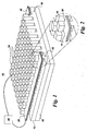
- FIGS. 1 and 2 illustrate a heat sink 10 with distributed jet cooling.
- the heat sink comprises a base 12 for thermal connection to at least one heated object 20.
- the heated object 20 may be any object requiring cooling, non-limiting examples of which include high power processors and power electronics.
- the base 12 base plate or sink plate
- the heat sink 10 further includes an array of fins 14 thermally coupled to the base. The fins may be arranged in a two-dimensional array of "pin fins" as shown, for example in FIG 1 .
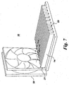
- the fins 14 may take the form of a one-dimensional array of "plate fins" defining slots between them, as shown for example in FIGS. 7 and 8 . Briefly, the heat from the heated object 20 is transferred into the base 12, which in turn transfers heat into the fins 14. The fins 14 increase the surface area for heat transfer for cooling the heated body 20.
- the heat sink 10 further includes at least one multi-orifice synthetic jet 30 disposed on a side 15, 16 of the array of fins.
- multiple single jets are disposed on the respective side 15, 16 of the array of fins.
- the multiple single jets are similar to the multi-orifice synthetic jets discussed herein, except that that the single jets include a single orifice.
- each of the multi-orifice synthetic jets 30 comprises a first flexible structure 32, a second flexible structure 34, at least one active material 36 coupled to at least one of the first and second flexible structures, and a compliant wall 38 positioned between the first and second flexible structures and defining a chamber. As indicated in FIG.
- the compliant wall defines multiple orifices 39 for facilitating fluid communication between the chamber and an ambient environment of the fins 14. It should be noted that the number of orifices shown in FIG. 3 is merely illustrative and is non-limiting.
- the compliant wall 38 comprises an elastomer.
- Other example materials for the compliant wall 38 include, without limitation, polymers, glues, adhesives, metals, and composites.
- the active material 36 is positioned on both of the first and second flexible structures 32, 34. It should be noted that the locations of the active materials 36 on the flexible structures 32, 34 shown in the figures are purely illustrative, and the invention is not limited to any specific locations of active materials.
- the active material is coextensive with the respective flexible structure. In other embodiments, the active material extends over only a portion of the flexible structure.
- the active material can take the form of a single continuous portion. Alternatively, multiple discontinuous portions of the active material can be employed to actuate respective ones of the flexible structures.
- a suitable active material is one, which is capable of creating stress resulting from an electrical stimulus.
- suitable active material examples include piezoelectric material, magnetostrictive material (magnetic fields from coils attract/oppose one another), shape-memory alloy, and motor imbalance (motor with a mass imbalance creates oscillatory motion).
- suitable active materials include bimorph piezoelectric configurations, where two piezo layers are energized out of phase to produce bending; thunder configurations, where one piezo layer is disposed on a prestressed stainless steel shim; buzzer element configurations, where one piezo layer is disposed on a brass shim; and MFC configurations, where a piezo fiber composite on a flexible circuit is bonded to a shim.
- the active material may incorporate a ceramic material.
- the heat sink 10 may comprise a stack 60 of the single or multi-orifice synthetic jets 30. Similar to the arrangement described with reference to FIGS. 1 and 2 , the stack 60 is disposed on one of the sides 15, 16 of the array of fins 14. Although FIG. 4 depicts a stack of two multi-orifice synthetic jets, the stack 60 may include any number of synthetic jets depending on the cooling application (for example, on the fin 14 height).
- the synthetic jets 30 may be separated by a spacer 42, as indicated in FIG. 4 . In one non-limiting example, the spacer 42 comprises plastic.
- a synthetic jet driver 40 is provided to apply an electrical current to the at least one active material 36, to form streams of ambient air.
- the synthetic jet driver 40 can be electrically coupled to the active material 136 using wires or flexible interconnects, for example.
- electrical current from synthetic jet driver 40 is received by the active material, and transformed into mechanical energy.
- the active material 36 creates stress on the flexible walls 32, 34, causing them to flex inwardly, resulting in a chamber volume change and an influx of ambient air into the chamber 70, and then outwardly, thereby ejecting the ambient air from the chambers 70 via the orifices 39.
- FIG. 5 the active material 36 creates stress on the flexible walls 32, 34, causing them to flex inwardly, resulting in a chamber volume change and an influx of ambient air into the chamber 70, and then outwardly, thereby ejecting the ambient air from the chambers 70 via the orifices 39.
- the synthetic jet driver 40 may be co-located with the other heat sink elements or may be remotely located.
- the current may be provided as a sine wave, a square wave, a triangular wave, or any other suitable waveform, and it should be appreciated that the current is not to be limited to any specific waveform. However, it has been found that currents having lower harmonics, such as, for example, a sine wave, may be used to provide a quieter synthetic jet 30.
- the voltage level for the electrical current may be between 1 and 150 volts but is not so limited.
- the frequency of the current may be between 2 and 300 hertz for embodiments requiring reduced noise, and between 300 hertz and 15 kilohertz for embodiments that do not require reduced noise levels.
- the heat sink 10 comprises multiple multi-orifice synthetic jets 30 disposed on respective sides 15, 16 of the array of fins 14.
- the orifices may be disposed, so as to direct air between the fins 14 and to draw air from between the fins 14.
- the orifices 39 may be configured in a variety of arrangements depending on the desired cooling flow and on the configuration of the array of fins 14. In one example arrangement, at least a subset of the orifices 39 are positioned to eject an ambient fluid directly on the fins 14. In another example arrangement, at least a subset of the orifices 39 are oriented at an angle transverse to an opposing surface 11 of the fins 14. For certain configurations, the ambient fluid is ejected perpendicular to a plane of the fins 14, as indicated for example in FIG. 5 .
- the heat sink 10 further comprises a fan 50 disposed on one of an inlet and an outlet side 21, 23 of the array of fins 14.
- the fan 50 is configured to draw the ambient fluid through the fins 14, and the ambient fluid drawn by the fan 50 interacts with the ambient fluid ejected from the multi-orifice synthetic jets or from the multiple single jets to further enhance the cooling by at least ten percent (10%) relative to a jet-free condition.
- the fan 50 is configured to push flow towards the array of fins.
- fans 50 disposed at the outlet side 23 of the array of fins are configured to pull flow through the array.
- FIG. 8 illustrates another arrangement, in which the fan 50 is disposed above the array of fins 14 and configured to blow an ambient fluid on the fins 14.
- FIGS. 1-6 A number of different fin configurations can be employed for the heat sink of FIGS. 1-6 .
- the fins 14 are pin fins and are arranged in a regular array.
- FIG. 15 illustrates another pin fin configuration for the heat sink 10 of FIGS. 1-6 , in which the fins 14 are staggered (offset) to provide a v-groove cooling configuration.
- FIG. 16 illustrates a v-groove plate fin configuration. Under specific circumstances, computer simulation results have demonstrated a thirty percent performance enhancement for the v-groove configuration relative to the conventional plate fin arrangement shown for example in FIGS. 7 and 8 .
- FIGS. 15 and 16 show v-groove configurations with symmetric v-grooves, the invention is not limited to these arrangements and can also employ asymmetric v-groove configurations.
- FIGS. 15 and 16 show v-grooves with centerlines aligned with the respective centerlines of the jets, offset arrangements may also be employed, in which the centerlines of the v-grooves are offset from the centerlines of the jets.
- combinations of these arrangements may also be employed (asymmetric v-grooves that are offset for the respective jets).
- FIGS. 9-11 illustrate another heat sink 100 embodiment of the invention with distributed and integrated jet cooling.
- the heat sink 100 includes a base 12 for thermal connection to at least one heated object 20.
- the invention is not limited to cooling a specific type of heated object, but rather can be used to cool a variety of heated objects.
- the heat sink 100 further includes an array of fins 114 thermally coupled to the base 12.
- a two-dimensional array of "plate fins" is employed.
- Respective ones of at least a subset of the fins comprise a synthetic jet 102 configured to eject an ambient fluid into an ambient environment of the fins and base.
- a synthetic jet 102 is inset into each of the fins 114.
- the synthetic jets 102 are shown in greater detail in FIG. 10 .
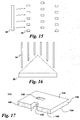
- FIG. 11 schematically depicts a single plate fin 114 with an integrated synthetic jet for use in the heat sink of FIGS. 9 and 10 .
- each of the fins 114 with an integrated jet 102 comprises a first flexible structure 132, a second structure 134, and at least one active material 136 coupled to the first flexible structure 132.
- the active material 136 is discussed above with reference to heat sink 10.
- example materials for the flexible structures 132, 134 include, without limitation, metal-based materials, such as aluminum and copper, composite structures, for example, carbon fiber filled materials, and thermally conductive polymer based materials.
- a compliant wall 138 is positioned between the first and second structures 132, 134 thereby forming a chamber.
- the compliant wall 138 defines at least one orifice 139 for facilitating fluid communication between the chamber and the ambient environment.
- the second structure 134 is flexible, and the active material 136 is coupled to at least one of the first and second flexible structures 132, 134.
- active material 136 is coupled to both flexible structures 132, 134, such that both of these walls are actuated.
- the active material can take the form of a single continuous portion. Alternatively, multiple discontinuous portions of the active material can be employed to actuate respective ones of the flexible structures.
- FIG. 17 illustrates a particular configuration of the fin 114 of FIGS. 9-11 with enhanced thermal coupling to the base of the heat sink.
- each of the fins 114 with an integral jet further comprises at least one thermally conductive portion 140 extending between the first and second structures 132, 134 and disposed to thermally couple the fin to the base 12.
- the fin 114 includes two thermally conductive portions 140.
- Non-limiting example materials for the thermally conductive portions 140 include metals, such as copper.
- the thermally conductive portions 140 are attached to the base plate, for example by brazing.
- At least one synthetic jet driver 40 is provided to actuate one or more of the synthetic jets 102.
- the synthetic jet driver 40 can be electrically coupled to the active material 136 using wires or flexible interconnects, for example.
- the synthetic jet driver 40 may be co-located with the other heat sink elements or may be remotely located.
- the operation of the synthetic jets 102 is similar to that of multi-orifice synthetic jets 30 described above with reference to FIGS. 5 and 6 .
- Advantages of the heat sink 100 embodiment described with reference to FIGS. 9-11 and 17 include a compact, relatively light design with increased surface area.
- the design is rugged, in that the active material is inherently protected by the fins.
- the synthetic jets 102 can be used alone or in combination with one or more fans 50, depending on the application.
- a fan 50 may be disposed on one of an inlet and an outlet side 121, 123 of the array of fins 114. The fan is configured to draw the ambient fluid through the fins 114, such that the ambient fluid drawn by the fan 50 interacts with the ambient air ejected from the synthetic jets 102 to further enhance the cooling.
- a fan 50 may be disposed above the array of fins 114 and configured to blow the ambient fluid on the fins 114.
- FIGS. 12-14 illustrate another heat sink 200 embodiment of the invention with distributed and integrated jet cooling.
- the heat sink 200 includes a base 12 for thermal connection to at least one heated object 20.
- the heated object 20 may be any object requiring cooling.
- the heat sink 200 further includes an array of fins 214 thermally coupled to the base 12. At least a subset of the fins comprise synthetic jets 202 configured to eject an ambient fluid into an ambient environment of the fins 214 and base 12.
- each of the fins 214 is coupled to a synthetic jet 202.
- synthetic jets 202 are provided for only a subset of the fins 214.
- FIG. 14 schematically depicts, in cross-sectional view, an example configuration of a synthetic jet 202 for use in the heat sink shown in FIGS.12 and 13 .
- the synthetic jet 202 comprises at least one flexible structure 232, a second structure 234, and at least one active material 236 coupled to the flexible structure 232.
- a compliant wall 238 is positioned between the flexible structure 232 and the second structure 234, thereby defining a chamber.
- the compliant wall defines at least one orifice, which is indicated by reference numeral 239, for facilitating fluid communication between the chamber and the ambient environment.
- Example active materials and example materials for the compliant wall are discussed above.
- Example materials for flexible structures 232, 234 include, but are not limited to metals, conductive polymers, and plastics.
- the second structure 234 comprises a second flexible structure 234, and the active material 236 is coupled to at least one of the first and second flexible structures.
- the active material 236 is coupled to both flexible structures 232, 234, such that both structures can be actuated, for example upon application of an electric current.
- the second flexible structure 234 is separated from the surface 211 of the fin 214 by a gap 216 when the synthetic jet 202 is in an unactuated state.
- synthetic jet 202 The operation of synthetic jet 202 is similar to that of synthetic jet 30, as discussed above with reference to FIGS. 5 and 6 .
- a synthetic jet driver 40 is provided to apply an electrical current to the at least one active material 236, to form streams of ambient air.
- the synthetic jet driver 40 can be electrically coupled to the active material 236 using wires or flexible interconnects, for example. Briefly, upon application of an electrical current from synthetic jet driver 40, the active material 236 creates stress on the flexible wall 232 causing it to flex inwardly, resulting in a chamber volume change and an influx of ambient air into the chamber 270, and then outwardly, thereby ejecting the ambient air from the chamber 270 via the orifice 239.
- the driver 40 actuates the jet 202.
- the synthetic jet driver 40 may be co-located with the other heat sink elements or may be remotely located.
- the current may be provided as a sine wave, a square wave, a triangular wave, or any other suitable waveform, and it should be appreciated that the current is not to be limited to any specific waveform.
- the synthetic jets 202 can be used alone or in combination with one or more fans 50, depending on the application.
- a fan 50 may be provided on one of an inlet and an outlet side 221, 223 of the array of fins 214, where the fan is configured to draw the ambient fluid through the fins, and where the ambient fluid drawn by the fan interacts with the ambient air ejected from the synthetic jets to further enhance the cooling.
- a fan 50 may be provided above the array of fins 214 and configured to blow the ambient fluid on the fins.
Landscapes
- Physics & Mathematics (AREA)
- Condensed Matter Physics & Semiconductors (AREA)
- General Physics & Mathematics (AREA)
- Engineering & Computer Science (AREA)
- Computer Hardware Design (AREA)
- Microelectronics & Electronic Packaging (AREA)
- Power Engineering (AREA)
- Cooling Or The Like Of Electrical Apparatus (AREA)
- Cooling Or The Like Of Semiconductors Or Solid State Devices (AREA)
Claims (3)
- Kühlkörper (10) mit verteilter Strahlkühlung, wobei der Kühlkörper Folgendes umfasst:eine Basis (12) zur thermischen Verbindung mit zumindest einem erwärmten Objekt (20);eine Anordnung von Rippen (14), die thermisch mit der Basis (12) gekoppelt sind, wobei die Rippen (14) stiftförmige Rippen oder plattenförmige Rippen umfassen, wobei die Rippen in einer versetzten Anordnung angeordnet sind, um einen keilnutförmigen Kühlaufbau bereitzustellen; undzumindest eine synthetische Düse (30) mit mehreren Öffnungen oder mehrere Düsen mit einer einzelnen Öffnung, die an einer Seite (15, 16) der Anordnung von Rippen angeordnet ist bzw. sind, wobei zumindest ein Untersatz der Öffnungen positioniert sind, um ein Umgebungsfluid direkt auf die Rippen (14) auszustrahlen, und wobei das Umgebungsfluid senkrecht zu einer Ebene der Rippen und eines Gebläses (50), das an einer aus einer Einlass- und einer Auslassseite (21, 23) der Anordnung von Rippen (14) angeordnet ist, ausgestrahlt wird, wobei das Gebläse dazu ausgebildet ist, das Umgebungsfluid durch die Rippen (14) zu ziehen, und wobei das Umgebungsfluid, das durch das Gebläse angezogen wird, mit dem Umgebungsfluid, das von den synthetischen Düsen mit mehreren Öffnungen oder den mehreren Düsen mit einer einzelnen Öffnung ausgestrahlt wird, zusammenwirkt, um die Kühlung in Bezug auf einen düsenfreien Zustand um zumindest zehn Prozent (10 %) zu steigern.
- Kühlkörper (10) nach Anspruch 1, wobei jede der synthetischen Düsen mit mehreren Öffnungen Folgendes umfasst:einen ersten biegsamen Aufbau (32);einen zweiten biegsamen Aufbau (34);zumindest ein aktives Material (36), das mit zumindest einem aus dem ersten und dem zweiten biegsamen Aufbau gekoppelt ist; undeine nachgiebige Wand (38), die zwischen dem ersten und dem zweiten biegsamen Aufbau positioniert ist und eine Kammer definiert, wobei die nachgiebige Wand mehrere Öffnungen (39) definiert, um die Fluidverbindung zwischen der Kammer und einer Umgebung der Rippen zu erleichtern.
- Kühlkörper (10) nach Anspruch 1 oder 2, ferner umfassend ein Gebläse (50), das über der Anordnung von Rippen (14) angeordnet ist und dazu ausgebildet ist, ein Umgebungsfluid auf die Rippen zu blasen.
Applications Claiming Priority (1)
| Application Number | Priority Date | Filing Date | Title |
|---|---|---|---|
| US12/421,068 US8496049B2 (en) | 2009-04-09 | 2009-04-09 | Heat sinks with distributed and integrated jet cooling |
Publications (3)
| Publication Number | Publication Date |
|---|---|
| EP2239775A2 EP2239775A2 (de) | 2010-10-13 |
| EP2239775A3 EP2239775A3 (de) | 2012-09-26 |
| EP2239775B1 true EP2239775B1 (de) | 2016-06-01 |
Family
ID=42272059
Family Applications (1)
| Application Number | Title | Priority Date | Filing Date |
|---|---|---|---|
| EP10158793.9A Not-in-force EP2239775B1 (de) | 2009-04-09 | 2010-03-31 | Kühlkörper mit verteilter und integrierter Strahlkühlung |
Country Status (4)
| Country | Link |
|---|---|
| US (1) | US8496049B2 (de) |
| EP (1) | EP2239775B1 (de) |
| JP (1) | JP5711468B2 (de) |
| CA (1) | CA2697870A1 (de) |
Families Citing this family (27)
| Publication number | Priority date | Publication date | Assignee | Title |
|---|---|---|---|---|
| WO2008075245A2 (en) * | 2006-12-15 | 2008-06-26 | Koninklijke Philips Electronics N.V. | Pulsating fluid cooling with frequency control |
| US8453715B2 (en) * | 2008-10-30 | 2013-06-04 | General Electric Company | Synthetic jet embedded heat sink |
| US9478479B2 (en) * | 2010-10-26 | 2016-10-25 | General Electric Company | Thermal management system and method |
| US9615482B2 (en) | 2009-12-11 | 2017-04-04 | General Electric Company | Shaped heat sinks to optimize flow |
| US10226991B2 (en) * | 2009-10-28 | 2019-03-12 | GM Global Technology Operations LLC | Air curtain using smart materials |
| US8776871B2 (en) * | 2009-11-19 | 2014-07-15 | General Electric Company | Chassis with distributed jet cooling |
| US8695686B2 (en) * | 2010-01-07 | 2014-04-15 | General Electric Company | Method and apparatus for removing heat from electronic devices using synthetic jets |
| US8760164B2 (en) | 2010-01-29 | 2014-06-24 | General Electric Company | Magnetic resonant imaging gradient driver architecture |
| US8506105B2 (en) | 2010-08-25 | 2013-08-13 | Generla Electric Company | Thermal management systems for solid state lighting and other electronic systems |
| JP5860665B2 (ja) * | 2010-10-26 | 2016-02-16 | ゼネラル・エレクトリック・カンパニイ | 熱管理システム及び方法 |
| US20120170216A1 (en) * | 2011-01-04 | 2012-07-05 | General Electric Company | Synthetic jet packaging |
| US11129299B2 (en) * | 2011-03-31 | 2021-09-21 | Tejas Network Limited | Heat sink |
| US9417017B2 (en) | 2012-03-20 | 2016-08-16 | Thermal Corp. | Heat transfer apparatus and method |
| US8976525B2 (en) * | 2012-07-31 | 2015-03-10 | General Electric Company | Systems and methods for dissipating heat in an enclosure |
| US9247672B2 (en) | 2013-01-21 | 2016-01-26 | Parker-Hannifin Corporation | Passively controlled smart microjet cooling array |
| US20140216696A1 (en) * | 2013-02-01 | 2014-08-07 | Alcatel Lucent | Cooling device and a cooling assembly comprising the cooling device |
| US9976762B2 (en) * | 2013-03-14 | 2018-05-22 | General Electric Company | Synthetic jet driven cooling device with increased volumetric flow |
| KR20150128939A (ko) | 2013-03-14 | 2015-11-18 | 제네럴 일렉트릭 컴퍼니 | 저 공명 음향 합성 제트 구조체 |
| US9415413B2 (en) | 2013-03-14 | 2016-08-16 | General Electric Company | Synthetic jet suspension structure |
| US10085363B2 (en) | 2014-05-22 | 2018-09-25 | General Electric Company | Integrated compact impingement on extended heat surface |
| US9879661B2 (en) | 2014-08-29 | 2018-01-30 | General Electric Company | Vibrational fluid mover jet with active damping mechanism |
| US10629514B2 (en) * | 2015-12-09 | 2020-04-21 | Ozyegin Universitesi | Heat sink cooling with preferred synthetic jet cooling devices |
| CN108393199B (zh) * | 2018-04-27 | 2024-05-10 | 清华大学 | 合成射流器 |
| CA3162874A1 (en) | 2019-12-29 | 2021-07-08 | David MENICOVICH | Temperature control using active flow control actuators |
| CN113365466B (zh) * | 2020-03-02 | 2022-09-16 | 杭州海康威视数字技术股份有限公司 | 一种电子设备 |
| CN111970897B (zh) * | 2020-08-06 | 2022-06-21 | 中国电子科技集团公司第三十八研究所 | 一种半包围式岛型肋杆旁孔扰流强化换热散热器 |
| US11570930B2 (en) | 2021-02-17 | 2023-01-31 | Meta Platforms, Inc. | IC package with embedded fan-based cooling system |
Family Cites Families (26)
| Publication number | Priority date | Publication date | Assignee | Title |
|---|---|---|---|---|
| JPH05251883A (ja) * | 1992-03-05 | 1993-09-28 | Fujitsu Ltd | 電子装置の冷却機構 |
| US5299090A (en) * | 1993-06-29 | 1994-03-29 | At&T Bell Laboratories | Pin-fin heat sink |
| US6123145A (en) * | 1995-06-12 | 2000-09-26 | Georgia Tech Research Corporation | Synthetic jet actuators for cooling heated bodies and environments |
| US6159764A (en) * | 1997-07-02 | 2000-12-12 | Micron Technology, Inc. | Varied-thickness heat sink for integrated circuit (IC) packages and method of fabricating IC packages |
| JP2001345585A (ja) * | 2000-06-01 | 2001-12-14 | Hitachi Kokusai Electric Inc | 放熱フィン |
| JP2002026214A (ja) * | 2000-07-12 | 2002-01-25 | Sumitomo Metal Ind Ltd | 電子部品冷却装置 |
| US6722581B2 (en) * | 2001-10-24 | 2004-04-20 | General Electric Company | Synthetic jet actuators |
| US6588497B1 (en) * | 2002-04-19 | 2003-07-08 | Georgia Tech Research Corporation | System and method for thermal management by synthetic jet ejector channel cooling techniques |
| US7055329B2 (en) * | 2003-03-31 | 2006-06-06 | General Electric Company | Method and apparatus for noise attenuation for gas turbine engines using at least one synthetic jet actuator for injecting air |
| US7204615B2 (en) * | 2003-03-31 | 2007-04-17 | Lumination Llc | LED light with active cooling |
| US6801430B1 (en) * | 2003-05-09 | 2004-10-05 | Intel Corporation | Actuation membrane to reduce an ambient temperature of heat generating device |
| US6937472B2 (en) * | 2003-05-09 | 2005-08-30 | Intel Corporation | Apparatus for cooling heat generating components within a computer system enclosure |
| JP2005011922A (ja) * | 2003-06-18 | 2005-01-13 | Mitsubishi Electric Corp | ヒートシンクを備えた両面銅貼り基板、およびこれを用いた半導体装置 |
| JP4677744B2 (ja) * | 2003-11-04 | 2011-04-27 | ソニー株式会社 | 噴流発生装置、電子機器及び噴流発生方法 |
| JP4572548B2 (ja) | 2004-03-18 | 2010-11-04 | ソニー株式会社 | 気体噴出装置 |
| US20060196638A1 (en) * | 2004-07-07 | 2006-09-07 | Georgia Tech Research Corporation | System and method for thermal management using distributed synthetic jet actuators |
| US7307841B2 (en) * | 2005-07-28 | 2007-12-11 | Delphi Technologies, Inc. | Electronic package and method of cooling electronics |
| US7336486B2 (en) * | 2005-09-30 | 2008-02-26 | Intel Corporation | Synthetic jet-based heat dissipation device |
| JP4844236B2 (ja) * | 2005-12-20 | 2011-12-28 | ソニー株式会社 | ノズル、噴流発生装置、冷却装置及び電子機器 |
| JP2008008230A (ja) | 2006-06-30 | 2008-01-17 | Sony Corp | 噴流発生装置、ノズル体及び電子機器 |
| CN101542724A (zh) * | 2006-11-30 | 2009-09-23 | 皇家飞利浦电子股份有限公司 | 脉动冷却系统 |
| US20080137289A1 (en) * | 2006-12-08 | 2008-06-12 | General Electric Company | Thermal management system for embedded environment and method for making same |
| JP2008280917A (ja) * | 2007-05-10 | 2008-11-20 | Alps Electric Co Ltd | 圧電式気体噴射装置 |
| US7633753B2 (en) * | 2007-09-27 | 2009-12-15 | Intel Corporation | Piezoelectric air jet augmented cooling for electronic devices |
| US7990705B2 (en) * | 2008-05-09 | 2011-08-02 | General Electric Company | Systems and methods for synthetic jet enhanced natural cooling |
| US8584735B2 (en) * | 2009-07-28 | 2013-11-19 | Aerojet Rocketdyne Of De, Inc. | Cooling device and method with synthetic jet actuator |
-
2009
- 2009-04-09 US US12/421,068 patent/US8496049B2/en not_active Expired - Fee Related
-
2010
- 2010-03-25 CA CA2697870A patent/CA2697870A1/en not_active Abandoned
- 2010-03-31 EP EP10158793.9A patent/EP2239775B1/de not_active Not-in-force
- 2010-04-07 JP JP2010088256A patent/JP5711468B2/ja not_active Expired - Fee Related
Also Published As
| Publication number | Publication date |
|---|---|
| CA2697870A1 (en) | 2010-10-09 |
| US20100258270A1 (en) | 2010-10-14 |
| US8496049B2 (en) | 2013-07-30 |
| JP5711468B2 (ja) | 2015-04-30 |
| EP2239775A3 (de) | 2012-09-26 |
| EP2239775A2 (de) | 2010-10-13 |
| JP2010245539A (ja) | 2010-10-28 |
Similar Documents
| Publication | Publication Date | Title |
|---|---|---|
| EP2239775B1 (de) | Kühlkörper mit verteilter und integrierter Strahlkühlung | |
| US10274264B2 (en) | Method and apparatus for improved cooling of a heat sink using a synthetic jet | |
| US8120908B2 (en) | Thermal management system for embedded environment and method for making same | |
| US9134078B2 (en) | Synthetic jet embedded heat sink | |
| USRE46003E1 (en) | Method and apparatus for reducing acoustic noise in a synthetic jet | |
| US20140216696A1 (en) | Cooling device and a cooling assembly comprising the cooling device | |
| US9474183B2 (en) | Chassis with distributed jet cooling | |
| JP6628980B2 (ja) | 拡張式熱表面に対する統合されたコンパクトな衝当 | |
| Maaspuro | Piezoelectric oscillating cantilever fan for thermal management of electronics and LEDs—A review | |
| EP2971794A2 (de) | Elektroaktives polymerbetätigtes luftstromwärmeverwaltungsmodul | |
| KR20230049729A (ko) | Mems-기반 냉각 시스템들을 제조하기 위한 방법 및 시스템 | |
| EP2378848B1 (de) | Chassis mit integrierter Strahlkühlung | |
| US20150247686A1 (en) | Cooling assembly | |
| JP2007192210A (ja) | ノズル、噴流発生装置、冷却装置及び電子機器 | |
| CN219865369U (zh) | 一种压电风扇、散热器及电子设备 |
Legal Events
| Date | Code | Title | Description |
|---|---|---|---|
| PUAI | Public reference made under article 153(3) epc to a published international application that has entered the european phase |
Free format text: ORIGINAL CODE: 0009012 |
|
| AK | Designated contracting states |
Kind code of ref document: A2 Designated state(s): AT BE BG CH CY CZ DE DK EE ES FI FR GB GR HR HU IE IS IT LI LT LU LV MC MK MT NL NO PL PT RO SE SI SK SM TR |
|
| PUAL | Search report despatched |
Free format text: ORIGINAL CODE: 0009013 |
|
| AK | Designated contracting states |
Kind code of ref document: A3 Designated state(s): AT BE BG CH CY CZ DE DK EE ES FI FR GB GR HR HU IE IS IT LI LT LU LV MC MK MT NL NO PL PT RO SE SI SK SM TR |
|
| RIC1 | Information provided on ipc code assigned before grant |
Ipc: F15D 1/00 20060101ALI20120820BHEP Ipc: H01L 23/467 20060101AFI20120820BHEP |
|
| 17P | Request for examination filed |
Effective date: 20130326 |
|
| 17Q | First examination report despatched |
Effective date: 20140724 |
|
| GRAP | Despatch of communication of intention to grant a patent |
Free format text: ORIGINAL CODE: EPIDOSNIGR1 |
|
| INTG | Intention to grant announced |
Effective date: 20160225 |
|
| GRAS | Grant fee paid |
Free format text: ORIGINAL CODE: EPIDOSNIGR3 |
|
| GRAA | (expected) grant |
Free format text: ORIGINAL CODE: 0009210 |
|
| AK | Designated contracting states |
Kind code of ref document: B1 Designated state(s): AT BE BG CH CY CZ DE DK EE ES FI FR GB GR HR HU IE IS IT LI LT LU LV MC MK MT NL NO PL PT RO SE SI SK SM TR |
|
| REG | Reference to a national code |
Ref country code: GB Ref legal event code: FG4D |
|
| REG | Reference to a national code |
Ref country code: CH Ref legal event code: EP Ref country code: AT Ref legal event code: REF Ref document number: 804330 Country of ref document: AT Kind code of ref document: T Effective date: 20160615 |
|
| REG | Reference to a national code |
Ref country code: IE Ref legal event code: FG4D |
|
| REG | Reference to a national code |
Ref country code: DE Ref legal event code: R096 Ref document number: 602010033740 Country of ref document: DE |
|
| REG | Reference to a national code |
Ref country code: LT Ref legal event code: MG4D |
|
| REG | Reference to a national code |
Ref country code: NL Ref legal event code: MP Effective date: 20160601 |
|
| PG25 | Lapsed in a contracting state [announced via postgrant information from national office to epo] |
Ref country code: NO Free format text: LAPSE BECAUSE OF FAILURE TO SUBMIT A TRANSLATION OF THE DESCRIPTION OR TO PAY THE FEE WITHIN THE PRESCRIBED TIME-LIMIT Effective date: 20160901 Ref country code: FI Free format text: LAPSE BECAUSE OF FAILURE TO SUBMIT A TRANSLATION OF THE DESCRIPTION OR TO PAY THE FEE WITHIN THE PRESCRIBED TIME-LIMIT Effective date: 20160601 Ref country code: LT Free format text: LAPSE BECAUSE OF FAILURE TO SUBMIT A TRANSLATION OF THE DESCRIPTION OR TO PAY THE FEE WITHIN THE PRESCRIBED TIME-LIMIT Effective date: 20160601 |
|
| REG | Reference to a national code |
Ref country code: AT Ref legal event code: MK05 Ref document number: 804330 Country of ref document: AT Kind code of ref document: T Effective date: 20160601 |
|
| PG25 | Lapsed in a contracting state [announced via postgrant information from national office to epo] |
Ref country code: GR Free format text: LAPSE BECAUSE OF FAILURE TO SUBMIT A TRANSLATION OF THE DESCRIPTION OR TO PAY THE FEE WITHIN THE PRESCRIBED TIME-LIMIT Effective date: 20160902 Ref country code: NL Free format text: LAPSE BECAUSE OF FAILURE TO SUBMIT A TRANSLATION OF THE DESCRIPTION OR TO PAY THE FEE WITHIN THE PRESCRIBED TIME-LIMIT Effective date: 20160601 Ref country code: HR Free format text: LAPSE BECAUSE OF FAILURE TO SUBMIT A TRANSLATION OF THE DESCRIPTION OR TO PAY THE FEE WITHIN THE PRESCRIBED TIME-LIMIT Effective date: 20160601 Ref country code: SE Free format text: LAPSE BECAUSE OF FAILURE TO SUBMIT A TRANSLATION OF THE DESCRIPTION OR TO PAY THE FEE WITHIN THE PRESCRIBED TIME-LIMIT Effective date: 20160601 Ref country code: ES Free format text: LAPSE BECAUSE OF FAILURE TO SUBMIT A TRANSLATION OF THE DESCRIPTION OR TO PAY THE FEE WITHIN THE PRESCRIBED TIME-LIMIT Effective date: 20160601 Ref country code: LV Free format text: LAPSE BECAUSE OF FAILURE TO SUBMIT A TRANSLATION OF THE DESCRIPTION OR TO PAY THE FEE WITHIN THE PRESCRIBED TIME-LIMIT Effective date: 20160601 |
|
| PG25 | Lapsed in a contracting state [announced via postgrant information from national office to epo] |
Ref country code: CZ Free format text: LAPSE BECAUSE OF FAILURE TO SUBMIT A TRANSLATION OF THE DESCRIPTION OR TO PAY THE FEE WITHIN THE PRESCRIBED TIME-LIMIT Effective date: 20160601 Ref country code: IT Free format text: LAPSE BECAUSE OF FAILURE TO SUBMIT A TRANSLATION OF THE DESCRIPTION OR TO PAY THE FEE WITHIN THE PRESCRIBED TIME-LIMIT Effective date: 20160601 Ref country code: SK Free format text: LAPSE BECAUSE OF FAILURE TO SUBMIT A TRANSLATION OF THE DESCRIPTION OR TO PAY THE FEE WITHIN THE PRESCRIBED TIME-LIMIT Effective date: 20160601 Ref country code: RO Free format text: LAPSE BECAUSE OF FAILURE TO SUBMIT A TRANSLATION OF THE DESCRIPTION OR TO PAY THE FEE WITHIN THE PRESCRIBED TIME-LIMIT Effective date: 20160601 Ref country code: EE Free format text: LAPSE BECAUSE OF FAILURE TO SUBMIT A TRANSLATION OF THE DESCRIPTION OR TO PAY THE FEE WITHIN THE PRESCRIBED TIME-LIMIT Effective date: 20160601 Ref country code: IS Free format text: LAPSE BECAUSE OF FAILURE TO SUBMIT A TRANSLATION OF THE DESCRIPTION OR TO PAY THE FEE WITHIN THE PRESCRIBED TIME-LIMIT Effective date: 20161001 |
|
| PG25 | Lapsed in a contracting state [announced via postgrant information from national office to epo] |
Ref country code: PT Free format text: LAPSE BECAUSE OF FAILURE TO SUBMIT A TRANSLATION OF THE DESCRIPTION OR TO PAY THE FEE WITHIN THE PRESCRIBED TIME-LIMIT Effective date: 20161003 Ref country code: BE Free format text: LAPSE BECAUSE OF FAILURE TO SUBMIT A TRANSLATION OF THE DESCRIPTION OR TO PAY THE FEE WITHIN THE PRESCRIBED TIME-LIMIT Effective date: 20160601 Ref country code: PL Free format text: LAPSE BECAUSE OF FAILURE TO SUBMIT A TRANSLATION OF THE DESCRIPTION OR TO PAY THE FEE WITHIN THE PRESCRIBED TIME-LIMIT Effective date: 20160601 Ref country code: AT Free format text: LAPSE BECAUSE OF FAILURE TO SUBMIT A TRANSLATION OF THE DESCRIPTION OR TO PAY THE FEE WITHIN THE PRESCRIBED TIME-LIMIT Effective date: 20160601 Ref country code: SM Free format text: LAPSE BECAUSE OF FAILURE TO SUBMIT A TRANSLATION OF THE DESCRIPTION OR TO PAY THE FEE WITHIN THE PRESCRIBED TIME-LIMIT Effective date: 20160601 |
|
| REG | Reference to a national code |
Ref country code: DE Ref legal event code: R097 Ref document number: 602010033740 Country of ref document: DE |
|
| PLBE | No opposition filed within time limit |
Free format text: ORIGINAL CODE: 0009261 |
|
| STAA | Information on the status of an ep patent application or granted ep patent |
Free format text: STATUS: NO OPPOSITION FILED WITHIN TIME LIMIT |
|
| 26N | No opposition filed |
Effective date: 20170302 |
|
| PG25 | Lapsed in a contracting state [announced via postgrant information from national office to epo] |
Ref country code: SI Free format text: LAPSE BECAUSE OF FAILURE TO SUBMIT A TRANSLATION OF THE DESCRIPTION OR TO PAY THE FEE WITHIN THE PRESCRIBED TIME-LIMIT Effective date: 20160601 Ref country code: DK Free format text: LAPSE BECAUSE OF FAILURE TO SUBMIT A TRANSLATION OF THE DESCRIPTION OR TO PAY THE FEE WITHIN THE PRESCRIBED TIME-LIMIT Effective date: 20160601 |
|
| REG | Reference to a national code |
Ref country code: DE Ref legal event code: R119 Ref document number: 602010033740 Country of ref document: DE |
|
| REG | Reference to a national code |
Ref country code: CH Ref legal event code: PL |
|
| GBPC | Gb: european patent ceased through non-payment of renewal fee |
Effective date: 20170331 |
|
| PG25 | Lapsed in a contracting state [announced via postgrant information from national office to epo] |
Ref country code: MC Free format text: LAPSE BECAUSE OF FAILURE TO SUBMIT A TRANSLATION OF THE DESCRIPTION OR TO PAY THE FEE WITHIN THE PRESCRIBED TIME-LIMIT Effective date: 20160601 |
|
| REG | Reference to a national code |
Ref country code: IE Ref legal event code: MM4A |
|
| REG | Reference to a national code |
Ref country code: FR Ref legal event code: ST Effective date: 20171130 |
|
| PG25 | Lapsed in a contracting state [announced via postgrant information from national office to epo] |
Ref country code: LU Free format text: LAPSE BECAUSE OF NON-PAYMENT OF DUE FEES Effective date: 20170331 Ref country code: FR Free format text: LAPSE BECAUSE OF NON-PAYMENT OF DUE FEES Effective date: 20170331 Ref country code: DE Free format text: LAPSE BECAUSE OF NON-PAYMENT OF DUE FEES Effective date: 20171003 |
|
| PG25 | Lapsed in a contracting state [announced via postgrant information from national office to epo] |
Ref country code: IE Free format text: LAPSE BECAUSE OF NON-PAYMENT OF DUE FEES Effective date: 20170331 Ref country code: GB Free format text: LAPSE BECAUSE OF NON-PAYMENT OF DUE FEES Effective date: 20170331 Ref country code: LI Free format text: LAPSE BECAUSE OF NON-PAYMENT OF DUE FEES Effective date: 20170331 Ref country code: CH Free format text: LAPSE BECAUSE OF NON-PAYMENT OF DUE FEES Effective date: 20170331 |
|
| PG25 | Lapsed in a contracting state [announced via postgrant information from national office to epo] |
Ref country code: MT Free format text: LAPSE BECAUSE OF NON-PAYMENT OF DUE FEES Effective date: 20170331 |
|
| PG25 | Lapsed in a contracting state [announced via postgrant information from national office to epo] |
Ref country code: HU Free format text: LAPSE BECAUSE OF FAILURE TO SUBMIT A TRANSLATION OF THE DESCRIPTION OR TO PAY THE FEE WITHIN THE PRESCRIBED TIME-LIMIT; INVALID AB INITIO Effective date: 20100331 |
|
| PG25 | Lapsed in a contracting state [announced via postgrant information from national office to epo] |
Ref country code: BG Free format text: LAPSE BECAUSE OF FAILURE TO SUBMIT A TRANSLATION OF THE DESCRIPTION OR TO PAY THE FEE WITHIN THE PRESCRIBED TIME-LIMIT Effective date: 20160601 |
|
| PG25 | Lapsed in a contracting state [announced via postgrant information from national office to epo] |
Ref country code: CY Free format text: LAPSE BECAUSE OF NON-PAYMENT OF DUE FEES Effective date: 20160601 |
|
| PG25 | Lapsed in a contracting state [announced via postgrant information from national office to epo] |
Ref country code: MK Free format text: LAPSE BECAUSE OF FAILURE TO SUBMIT A TRANSLATION OF THE DESCRIPTION OR TO PAY THE FEE WITHIN THE PRESCRIBED TIME-LIMIT Effective date: 20160601 |
|
| PG25 | Lapsed in a contracting state [announced via postgrant information from national office to epo] |
Ref country code: TR Free format text: LAPSE BECAUSE OF FAILURE TO SUBMIT A TRANSLATION OF THE DESCRIPTION OR TO PAY THE FEE WITHIN THE PRESCRIBED TIME-LIMIT Effective date: 20160601 |