EP2237639A1 - Dispositif et procédé permettant de chauffer un matériau - Google Patents
Dispositif et procédé permettant de chauffer un matériau Download PDFInfo
- Publication number
- EP2237639A1 EP2237639A1 EP08871425A EP08871425A EP2237639A1 EP 2237639 A1 EP2237639 A1 EP 2237639A1 EP 08871425 A EP08871425 A EP 08871425A EP 08871425 A EP08871425 A EP 08871425A EP 2237639 A1 EP2237639 A1 EP 2237639A1
- Authority
- EP
- European Patent Office
- Prior art keywords
- heating
- heated
- plate material
- heating elements
- contact
- Prior art date
- Legal status (The legal status is an assumption and is not a legal conclusion. Google has not performed a legal analysis and makes no representation as to the accuracy of the status listed.)
- Granted
Links
Images


Classifications
-
- B—PERFORMING OPERATIONS; TRANSPORTING
- B21—MECHANICAL METAL-WORKING WITHOUT ESSENTIALLY REMOVING MATERIAL; PUNCHING METAL
- B21D—WORKING OR PROCESSING OF SHEET METAL OR METAL TUBES, RODS OR PROFILES WITHOUT ESSENTIALLY REMOVING MATERIAL; PUNCHING METAL
- B21D37/00—Tools as parts of machines covered by this subclass
- B21D37/16—Heating or cooling
-
- C—CHEMISTRY; METALLURGY
- C21—METALLURGY OF IRON
- C21D—MODIFYING THE PHYSICAL STRUCTURE OF FERROUS METALS; GENERAL DEVICES FOR HEAT TREATMENT OF FERROUS OR NON-FERROUS METALS OR ALLOYS; MAKING METAL MALLEABLE, e.g. BY DECARBURISATION OR TEMPERING
- C21D1/00—General methods or devices for heat treatment, e.g. annealing, hardening, quenching or tempering
- C21D1/34—Methods of heating
- C21D1/40—Direct resistance heating
-
- C—CHEMISTRY; METALLURGY
- C21—METALLURGY OF IRON
- C21D—MODIFYING THE PHYSICAL STRUCTURE OF FERROUS METALS; GENERAL DEVICES FOR HEAT TREATMENT OF FERROUS OR NON-FERROUS METALS OR ALLOYS; MAKING METAL MALLEABLE, e.g. BY DECARBURISATION OR TEMPERING
- C21D1/00—General methods or devices for heat treatment, e.g. annealing, hardening, quenching or tempering
- C21D1/62—Quenching devices
- C21D1/673—Quenching devices for die quenching
-
- F—MECHANICAL ENGINEERING; LIGHTING; HEATING; WEAPONS; BLASTING
- F27—FURNACES; KILNS; OVENS; RETORTS
- F27D—DETAILS OR ACCESSORIES OF FURNACES, KILNS, OVENS, OR RETORTS, IN SO FAR AS THEY ARE OF KINDS OCCURRING IN MORE THAN ONE KIND OF FURNACE
- F27D11/00—Arrangement of elements for electric heating in or on furnaces
- F27D11/02—Ohmic resistance heating
-
- F—MECHANICAL ENGINEERING; LIGHTING; HEATING; WEAPONS; BLASTING
- F27—FURNACES; KILNS; OVENS; RETORTS
- F27D—DETAILS OR ACCESSORIES OF FURNACES, KILNS, OVENS, OR RETORTS, IN SO FAR AS THEY ARE OF KINDS OCCURRING IN MORE THAN ONE KIND OF FURNACE
- F27D99/00—Subject matter not provided for in other groups of this subclass
- F27D99/0001—Heating elements or systems
- F27D99/0006—Electric heating elements or system
Definitions
- the present invention relates to a heating equipment and a heating method for heating a plate material to be heated, and particularly the invention relates to a heating equipment and a heating method for heating a material to be heated by directly contacting a plurality of heating elements with the material to be heated.
- a hot press-forming is a public technique to press a heated steel material in a hot state for forming automobile parts and the like.
- a low-temperature press die(s) when quenching the material with a low-temperature press die(s) at the same time of the press-forming, it is possible to form a part that have excellent characteristics such as a high tensile strength and the like.
- Patent Document 1 discloses a technique to contain a thermal diffusion plate inside a block to obtain a uniform temperature of a heating surface of the block as far as possible.
- Patent Document 2 discloses a heating equipment for heating a metal plate by transferring heat from a heat source such as a block heater to the metal plate via a heat conducting body.
- Patent Document 1 Japanese Patent Kokai Publication No. JP-A-11-145166
- Patent Document 2 Japanese Patent Kokai Publication No. JP-P2006-110549A
- Patent Documents 1 and 2 are incorporated herein by reference thereto.
- the analysis on the related art is set forth below by the present invention.
- the block heating is a method to heat a steel plate by contacting a metal block, which is heated by heaters internally embedded, with the steel plate.
- a material for a block is limited to that causes small thermal deformation or distortion even when the block is heated up to high temperature so as to assure a tight contact of the block with a steel plate.
- the block should be in tight contact with embedded heaters so as to ensure heating of the block itself and therefore, it is necessary to machine and assemble the block and heaters with high accuracy and materials of less thermal deformation or distortion are required again for this point of view.
- a heating equipment for a plate material to be heated wherein a contact-heating surface or surfaces is/are configured by arranging a plurality of heating elements at predetermined intervals, in a planar fashion and in a predetermined pattern on a base plate having a heat-insulating property, and the contact-heating surface(s) is/are directly contacted with the plate material to be heated for heating the plate material.
- the heating element is rod-shaped or strip-shaped with a rectangular section or rod-shaped with a circular or ellipsoidal section.
- a surface contacting with the plate material to be heated has a convex curved (profiled) surface along the whole length of the heating element.
- an insulation material is provided between the plurality of heating members and the insulation member is elastic or structured such that the insulation member can change its position in an orthogonal direction relative to the contact-heating surface.
- a plurality of the base plates each having a heat-insulating property and configuring the contact-heating surface(s) by arranging the plurality of heating elements, is arranged on both sides of the plate material to be heated and the plate material is sandwiched by the base plates to make a direct contact with the contact-heating surface of the heating elements for heating the plate material.
- the plurality of heating elements arranged on both sides of the plate material to be heated are arranged alternately on both sides and such that orthogonal projections of the heating elements on both sides on a plane parallel to the base plates overlap partially each other.
- the heating elements is arranged such that, in a case where the heating elements on the base plates on both sides are contacted with each other without the plate material to be heated, a contacting point corresponds to a cross point of convex curved surface portions and a line connecting both curvature centers of the convex curved surface portions of both of the heating elements near the contacting point.
- the base plate is configured by a plurality of units including a plurality of the heating elements.
- heating abilities of the plurality of heating elements can be controlled for every heating element or every unit, and can be determined in a desired heating pattern.
- the base plate is comprised of ceramics.
- a heating method for a plate material to be heated which comprises: configuring a contact-heating surface or surfaces by arranging a plurality of heating elements at predetermined intervals, in a planar fashion and in a predetermined pattern on a base plate having a heat-insulating property, and providing the base plates on both sides of the plate material to be heated and sandwiching the plate material to make a direct contact with the contact-heating surface or surfaces of the heating elements for heating the plate material.
- the equipment becomes small in size, simple in structure and low in cost because a block is eliminated (i.e., not used). It is possible to heat a material to be heated quickly because heating elements are directly contacted with a material.
- the equipment may be replaced by each unit and therefore repairs of the equipment become easy.
- a degree of freedom of heating is high because control of heating by each unit or each heating element may be possible.
- heating source may be off during a non-use period because the equipment can be heated in a short time and therefore, energy saving can be achieved.
- Two or more heating elements are arranged at specified intervals and in planar fashion on a base plate having a heat-insulating property. It is designated as a "unit". Ceramics etc. can be used for the base plate.
- the heating element has a rod-type or strip-type shape of a rectangular section or has a rod-type shape of a circular or oval (ellipsoidal) section, and the heating elements are arranged such that heating surfaces of the heating elements contacting with a material to be heated should contact with the material uniformly as a whole.
- each contact surface with the material to be heated may be flat; however, more tight contact may be obtained by making the contact surfaces into convex curved surfaces and by press-contacting with load (or pressure). It is preferable that a ratio of a height of the convex curved surface to a width of the heating element has certain specified value.
- a contact-heating surface having a necessary heating area is obtained by arranging the one or more units in planar fashion.
- the material to be heated is heated by directly contacting the contact-heating surface with the material. By this method the material to be heated can be rapidly heated efficiently.
- a width of the unit may range approximately 50 to 200 mm and a length may range approximately 100 to 1500 mm.
- a heating area which is necessary for a material to be heated can be obtained by combining sufficient number of the units. The area is not limited but may be, presumably, approximately 4000 mm x 3000 mm at the largest.
- a known heater such as an electric heater, sheath heater or gas heater (radiant tube heater), and the like may be used with respect to a temperature required.
- the heater is generally used having a rod-shape or strip-shape with a length, approximately, of 100 to 1500 mm and having a rectangular, round or oval section with one side length or diameter, approximately, of 5 to 200 mm.
- Insulators are provided between heating elements. They have a role to heat a material to be heated uniformly by suppressing heat radiation from portions without heaters and, when the heating elements are arranged alternately on both sides, to make a tight contact of the heating elements and the material to be heated by pressing the material from opposite side of the heating element. In addition, they have an effect to make it easy to separate the material to be heated and the heating elements when the pressing force from the heating elements is released after heating.
- heat insulation members When heating elements are arranged alternately on both sides, heat insulation members have elasticity or a structure so as to change its vertical position or horizontal position, etc. so as to make the heating elements contact tight with a material to be heated when the heating elements ware press-contacted with the material to be heated. Glass wool or asbestos and the like is used for the heat insulation member.
- a material to be heated may be heated from only one side.
- a plate material to be heated may be heated from both sides of the plate material by arranging a plurality of units on both sides and press-contacting the intervened plate material.
- a material to be heated may be sandwiched from upside and downside; however, it may be possible to sandwich from right side and left side or in an oblique direction tilted from the up and down (vertical) direction or the right and left (horizontal) direction.
- a contact surface of a heating element with a material to be heated may be flat; however, the contact of the heating element with the material may become more secured by forming the contact surfaces of the heating elements in a convex curved (profiled) surface (convex curved surface portion) and press-contacting them against the material from both sides.
- the heating elements on both sides are arranged alternately. That is, heating elements are not arranged on regions where heating elements are arranged at corresponding opposite side and heating elements are arranged on regions where no heating element is arranged at corresponding opposite side. However, it is preferable to arrange the heating elements such that parts (edges) of the heating elements are overlapping each other.
- the "partial overlapping" means that when the heating elements on both sides are perpendicularly projected on a plane parallel to a base plate, the projected images overlap partially each other.
- the heating elements When arranging the heating elements partially overlapped, it is preferable to arrange such that the material to be heated should contact with at least one of the heating elements on both sides and that an area which contacts with the heating elements on both sides at the same time should be minimized.
- the arrangement may be performed according the following concept. When contacting heating elements on both sides with each other without a material to be heated, both edge portions (correspond to edge portions of a section orthogonal to longitudinal axis of a rod-type heating element) of convex curved surface portions of the heating elements will contact with each other.
- the heating elements may be arranged such that a contacting point corresponds to a cross (intersection) point of a line connecting both curvature centers of convex curved surface portions (of both of the heating elements) containing the contacting point and the convex curved surface portion of the heating element.
- An effect of uniform heating of whole material to be heated can be obtained by arranging the heating elements on both sides in partially overlapping manner in such a way, contacting whole of the material to be heated with at least one of the heating elements and reducing an area which contacts with the heating elements on both sides at the same time.
- the present heating equipment has a heating control system that can control heating capacity of every heating element or every unit.
- any heating patterns or heating temperatures can be freely selected according to sizes or shapes of a material to be heated. It contributes to energy saving because unnecessary heating elements are not heated up and heating of whole equipment can be turned off during a waiting time since it can be heated up quickly.
- Fig. 1 illustrates a basic structure of a heating equipment of an example of the present invention.
- a plate material (material to be heated) 1 made of a high-tensile steel, for example, is sandwiched from upside and downside by two base plates (upper base plate 3 and lower base plate 4) on which heaters (heating elements) 2 are arranged, and the plate material 1 is heated by the heaters 2 that biases the plate material 1 from upside and directly contacts with the plate material (press-contacting).
- the upper base plate 3 and the heaters 2 thereon are illustrated as an assembly drawing.
- the heaters 2 of the example are sheath heaters having a rod shape. A section of each heater perpendicular to its longitudinal direction is nearly rectangular and a contacting surface with the plate material 1 has a convex curved (profiled) surface.
- the number of the heaters 2 is not limited; however, in this example, four heaters 2 are arranged in planar fashion (so as to contact with the plate material 1 uniformly) on each base plate.
- a base plate on which two or more heaters 2 are arranged is called as a unit and a unit on the upper side of the material to be heated is called as an upper unit 6 and a unit on the lower side of the material to be heated is called as a lower unit 7.
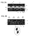
- Fig. 2 shows schematic sectional views of the plate material 1 sandwiched between the upper and lower units 6 and 7, which are perpendicular to a longitudinal direction of the heater 2, and Fig. 2A shows a section before sandwiching and Fig. 2B shows a section after sandwiching.
- elastic heat insulation members 5 are arranged between the heaters 2 of each unit such that the elastic heat insulation members project from top surfaces (convex curved surface portion 2a) of the heaters 2. Glass wool or asbestos, for example, is used for a material of the heat insulation member 5.
- Purposes of the heat insulation member are, on the one hand, for heating the whole plate material 1 uniformly by heat-retaining a plate surface where the heater 2 is not contacted with and, on the other hand, for keeping sufficient contact of the plate material 1 with the heater 2 by pressing the plate material 1 from the opposite side of the heater 2.
- a contacting surface of the heater 2 and the plate material 1 is a convex curved surface portion 2a which curves gently.
- a heater 2 at the one end of each unit and a heat insulation member 5 on the other end of the each unit.
- the heaters 2 and heat insulation members 5 can be arranged alternately as a whole without a gap thereby when a plurality of the units are combined.
- Fig. 2B is a section in which the plate material 1 is sandwiched by the upper unit 6 from upper side with a pressing force.
- the plate material 1 curves along the convex curved surface portions 2a so as to contact with the heaters 2 without a gap when the plate material 1 is sandwiched by the units.
- the heat insulation members 5 deform elastically along the plate material 1 and contact with the plate material 1, and thus the heat radiation is restrained and the plate material 1 is heated uniformly as a whole.
- the convex curved surface portion 2a of the heater 2 is formed such that a height "h" of the convex curved surface portion ranges 1 to 20% relative to a section width "W" of the heater 2, and particularly the ratio is preferably about 10%.
- the heaters 2 are arranged such that positions of the heaters of the upper and lower base plates are arranged alternately. It means that heat insulation members 5, instead of heaters 2, are located on the lower base plate 4 in regions where heaters 2 are located on the upper base plate 3, and heaters 2 are located on the lower base plate 4 in regions where insulation members 5, instead of heaters 2, are located on the upper base plate 3. Thereby the number of the heaters 2 can be minimized. As shown in an enlarged drawing (shown in an oval, provided that the plate material 1 is omitted) in Fig. 2B , however, it is preferable to arrange the upper and lower heaters partially (at a portion shown as "X" in the drawing) overlapped. The whole plate material 1 will contact with the heater at least one of the upper and lower heaters and can be heated uniformly as a whole.
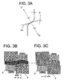
- Fig. 3B shows a schematic sectional view when the plate material 1 is sandwiched by the upper and lower heaters 2 that are arranged partially overlapped.
- the sign "X" indicates overlapping region of the heater and the sign "y” indicates a region, as shown in a circle in the drawing, where the plate material 1 contacts with both the upper and lower heaters 2.
- Fig. 3C shows a drawing in a case when the region "y" becomes zero as shown in a circle in the drawing, and this type of contact is desirable.
- Fig. 3A shows a schematic sectional view when the upper and lower heaters 2 are contacted each other without the plate material 1 (material to be heated).
- a part of the convex curved surface portion 2a including a region around a contact point (edge portion of the heating element) is a curved surface having a some curvature as shown in a dotted line in the drawing and a center of curvature of the lower heater 2 is designated as C and a center of curvature of the upper heater 2 is designated as C'.
- the heaters are formed and arranged such that a cross (intersection) point of an imaginary segment line connecting the C and C' and convex curved surface portions 2a of the both heaters 2 registers with the contacting point.
- a curved surface may be formed on the plate material 1 as a material to be heated because the contacting surface (convex curved surface portion 2a) of the heater 2 to the plate material 1 is curved, it does not become a problem because the curved surface of the plate material 1 is eliminated during a processing of the plate material 1 into a determined shape at a press step after heating.
- Fig. 4 shows schematic sectional views of a heating equipment of an example 2 of the present invention.
- heat insulation blocks 8 having no elasticity instead of the elastic heat insulation member 5 arranged between the heaters 2, are elastically connected to the upper and lower base plates 3 and 4 by spring members 9 so as to be able to change positions of the heat insulation blocks 8 in a height direction (up and down, i.e., vertical direction).
- Fig. 4A shows a section illustrating the plate material 1 as a material to be heated before sandwiched by the upper and lower units 6 and 7 and the heat insulation blocks 8 are held by the spring members 9 at height positions projecting from the contacting surfaces of the heaters 2.
- Fig. 4B shows a section illustrating the plate material 1 after sandwiched by the upper and lower units 6 and 7.
- the plate material 1 is press-contacted by the heaters 2 on both upper and lower sides and the heat insulation blocks 8 are pushed down (retracted) and are in contact with the plate material 1.
- Other structures are the same as an example 1 and, for example, the upper and lower heaters 2 are arranged slightly overlapped.
- a structure may be adopted in which holes are provided on the base plates 3 and 4 to connect the spring members 9 at the bottoms of the holes so as to be contracted and received in the holes for protecting the spring members 9 from the high temperature when the plate material is sandwiched (not shown).
- Fig. 5 shows a schematic sectional view of a heating equipment (plate material 1 is heated) of an example 3 of the present invention in which a radiant tube heater having a circular section is employed as a heating element 2.
- a radiant tube heater 2 is a rod-type heat element having a circular section of a heating portion.
- a radiant tube heater having a diameter of approximately 200 mm is under practical use.
- This type of radiant tube heaters are arranged on the upper and lower base plates 3 and 4 alternately as shown in examples 1 and 2.
- the plate material 1 is heated by being sandwiched by the upper and lower radiant tube heaters 2.
- the radiant tube heaters 2 are arranged such that upper heaters and lower heaters are overlapped to some extent (indicated as "X" in Fig. 5 ) and the plate material 1 is in contact with at least one of the upper and lower radiant tube heaters 2 as a whole.
- Heat insulation members 5 are arranged between the radiant tube heaters 2 on each base plate so that the whole plate material 1 can be heated uniformly.
- the heating equipment according to the present invention can form a wide heating area by arranging a plurality of base plates (units) each having two or more heating elements. Further, a heating ability (capacity) may be controlled by every heater or every unit using a heating control system 15 according to a size or shape of a material to be heated.
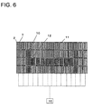
- Fig. 6 shows a schematic drawing of a heating equipment of an example 4 of the present invention indicating a structure and a mode of use. In this example 4, one heating equipment is configured by arranging four lower units 7 in a longitudinal direction and fifteen lower units 7 in transverse direction, in each unit three heaters 2 are arranged on a base plate.
- hot (heat-radiating) heaters 10 are shown by black and thick lines and cool (non heat-radiating) heaters 11 are shown by white lines in case of heating a steel plate (material to be heated) 12 for forming a door beam as a part for a vehicle.
- cool (non heat-radiating) heaters 11 are shown by white lines in case of heating a steel plate (material to be heated) 12 for forming a door beam as a part for a vehicle.
- a shape of the steel plate (material to be heated) 12 for the door beam is shown by white in a dotted line. Only an area necessary for heating according to the size and shape of the steel plate (material to be heated) 12 for the door beam can be heated as shown in the drawing.
- upper units 6 corresponding to the lower units 7 may be arranged and used by combining them as explained above in examples 1 to 3. Such a combination can be applied in the following examples.
- Fig. 7 shows an arrangement of heaters 2 when heating a different material to be heated (steel plate for forming a bumper) 13 using a heating equipment in which four units are arranged in longitudinal direction and fifteen units are arranged in a transverse direction, arranging three heaters 2 on a base plate of each unit as explained in example 4. Also, hot heaters 10 are shown in black and thick lines and cool heaters 11 are shown in white lines. A shape of the steel plate for a bumper (material to be heated) 13 is shown in a white and dotted line.
- Fig. 8 shows a heating area of the same heating equipment as examples 4 and 5 for heating a different material to be heated (steel plate for forming a B-pillar) 14 using the heating equipment. Also, hot heaters 10 are shown in black and thick lines and cool heaters 11 are shown in white lines. A shape of the steel plate for a B-pillar (material to be heated) 14 is shown in a white and dotted line.
- the heating equipment of the present invention is applicable in the case where a part of a material should be heated at a higher temperature and the other part of the material may be heated at a lower temperature.
- Fig. 9 shows a heating area in the case that the degree of heating is changed from example 6 by each heater 2 (or unit) (heating control system 15 is not shown).
- FIG. 9 shows an example in which (a part of heaters of) units arranged at right side by four in the longitudinal direction and by five in the transverse direction (indicated by slanting lines) are heated at a relatively low temperature that is lower than A1 transformation temperature of a steel (designated as L) and (a part of heaters of) the other parts of the units (indicated by black lines) are heated at a relatively high temperature that is higher than the A1 transformation temperature of a steel (designated as H) and that the steel can be quenched.
- a material to be heated can be heated by any desirable heating pattern and any heating temperature according to a position or a shape of the material to be heated.
Applications Claiming Priority (2)
| Application Number | Priority Date | Filing Date | Title |
|---|---|---|---|
| JP2008014434A JP4812785B2 (ja) | 2008-01-25 | 2008-01-25 | 被加熱材の加熱装置及び加熱方法 |
| PCT/JP2008/069117 WO2009093365A1 (fr) | 2008-01-25 | 2008-10-22 | Dispositif et procédé permettant de chauffer un matériau |
Publications (3)
| Publication Number | Publication Date |
|---|---|
| EP2237639A1 true EP2237639A1 (fr) | 2010-10-06 |
| EP2237639A4 EP2237639A4 (fr) | 2013-01-09 |
| EP2237639B1 EP2237639B1 (fr) | 2019-08-21 |
Family
ID=40900881
Family Applications (1)
| Application Number | Title | Priority Date | Filing Date |
|---|---|---|---|
| EP08871425.8A Not-in-force EP2237639B1 (fr) | 2008-01-25 | 2008-10-22 | Dispositif et procédé permettant de chauffer un matériau |
Country Status (4)
| Country | Link |
|---|---|
| US (1) | US8455801B2 (fr) |
| EP (1) | EP2237639B1 (fr) |
| JP (1) | JP4812785B2 (fr) |
| WO (1) | WO2009093365A1 (fr) |
Cited By (4)
| Publication number | Priority date | Publication date | Assignee | Title |
|---|---|---|---|---|
| WO2016012442A1 (fr) | 2014-07-23 | 2016-01-28 | Voestalpine Stahl Gmbh | Procédé de chauffage de tôles d'acier et dispositif permettant de mettre en œuvre ledit procédé |
| EP3276012A1 (fr) * | 2016-07-29 | 2018-01-31 | Benteler Automobiltechnik GmbH | Station de chauffage avec conducteur chauffant en gaine |
| EP3530760A1 (fr) * | 2018-02-23 | 2019-08-28 | Benteler Automobiltechnik GmbH | Procédé de fabrication d'un élément en tôle d'acier formé à chaud et durcis |
| EP4190922A1 (fr) * | 2021-12-01 | 2023-06-07 | GEDIA Gebrüder Dingerkus GmbH | Dispositif de blindage pour platines |
Families Citing this family (9)
| Publication number | Priority date | Publication date | Assignee | Title |
|---|---|---|---|---|
| JP2011255413A (ja) * | 2010-06-11 | 2011-12-22 | Toyoda Iron Works Co Ltd | 鋼板の加熱装置、プレス成形品の製造方法、およびプレス成形品 |
| ES2609328T3 (es) * | 2010-10-05 | 2017-04-19 | Schwartz Gmbh | Procedimiento y horno para tratar piezas de trabajo |
| JP5788625B2 (ja) * | 2012-04-03 | 2015-10-07 | ティッセンクルップ スチール ヨーロッパ アクチェンゲゼルシャフトThyssenKrupp Steel Europe AG | 少なくとも部分的に閉じたプロファイルまたは管状部品を金属薄板から製作する装置および方法 |
| US9303880B1 (en) | 2012-04-10 | 2016-04-05 | L.B. White Company, Inc. | Radiant tube heater |
| US20150352621A1 (en) | 2013-01-11 | 2015-12-10 | Futaba Industrial Co., Ltd. | Heating device for hot stamping |
| US9029740B2 (en) * | 2013-01-15 | 2015-05-12 | Nordson Corporation | Air impingement heater |
| DE102014101539B9 (de) | 2014-02-07 | 2016-08-11 | Benteler Automobiltechnik Gmbh | Warmformlinie und Verfahren zur Herstellung von warmumgeformten Blechprodukten |
| DE102015101668A1 (de) * | 2015-02-05 | 2016-08-11 | Benteler Automobiltechnik Gmbh | Zweifach fallendes Heiz- und Formwerkzeug sowie Verfahren zur Herstellung warmumgeformter und pressgehärteter Kraftfahrzeugbauteile |
| KR20210150035A (ko) | 2020-06-03 | 2021-12-10 | 주식회사 엘지에너지솔루션 | 유체를 포함하는 가압장치 및 이를 이용한 전극 및 전극 및 전극조립체 제조방법 |
Citations (3)
| Publication number | Priority date | Publication date | Assignee | Title |
|---|---|---|---|---|
| JP2003053437A (ja) * | 2001-08-10 | 2003-02-26 | Niigata Prefecture | マグネシウム合金の連続プレス加工装置 |
| US6578399B1 (en) * | 1999-09-09 | 2003-06-17 | Northrop Grumman Corporation | Single-die modularized, reconfigurable honeycomb core forming tool |
| JP2006110549A (ja) * | 2004-10-12 | 2006-04-27 | Aisin Takaoka Ltd | 熱間プレス用金属板の加熱装置 |
Family Cites Families (6)
| Publication number | Priority date | Publication date | Assignee | Title |
|---|---|---|---|---|
| JPS5213537U (fr) * | 1975-07-17 | 1977-01-31 | ||
| JPS59165395A (ja) * | 1983-03-09 | 1984-09-18 | いすゞ自動車株式会社 | 発熱体 |
| JPS61259482A (ja) * | 1985-05-14 | 1986-11-17 | 株式会社 八光電機製作所 | 熱板または金型等の表面温度の制御方法 |
| JPH0663926B2 (ja) | 1987-06-25 | 1994-08-22 | 株式会社豊田自動織機製作所 | バッテリ車の自己診断装置 |
| JPH01146528U (fr) * | 1988-03-30 | 1989-10-09 | ||
| JP3767986B2 (ja) | 1997-11-13 | 2006-04-19 | 株式会社九州日昌 | ブロックヒータ |
-
2008
- 2008-01-25 JP JP2008014434A patent/JP4812785B2/ja not_active Expired - Fee Related
- 2008-10-22 WO PCT/JP2008/069117 patent/WO2009093365A1/fr active Application Filing
- 2008-10-22 US US12/812,871 patent/US8455801B2/en not_active Expired - Fee Related
- 2008-10-22 EP EP08871425.8A patent/EP2237639B1/fr not_active Not-in-force
Patent Citations (3)
| Publication number | Priority date | Publication date | Assignee | Title |
|---|---|---|---|---|
| US6578399B1 (en) * | 1999-09-09 | 2003-06-17 | Northrop Grumman Corporation | Single-die modularized, reconfigurable honeycomb core forming tool |
| JP2003053437A (ja) * | 2001-08-10 | 2003-02-26 | Niigata Prefecture | マグネシウム合金の連続プレス加工装置 |
| JP2006110549A (ja) * | 2004-10-12 | 2006-04-27 | Aisin Takaoka Ltd | 熱間プレス用金属板の加熱装置 |
Non-Patent Citations (1)
| Title |
|---|
| See also references of WO2009093365A1 * |
Cited By (5)
| Publication number | Priority date | Publication date | Assignee | Title |
|---|---|---|---|---|
| WO2016012442A1 (fr) | 2014-07-23 | 2016-01-28 | Voestalpine Stahl Gmbh | Procédé de chauffage de tôles d'acier et dispositif permettant de mettre en œuvre ledit procédé |
| US10612108B2 (en) | 2014-07-23 | 2020-04-07 | Voestalpine Stahl Gmbh | Method for heating steel sheets and device for carrying out the method |
| EP3276012A1 (fr) * | 2016-07-29 | 2018-01-31 | Benteler Automobiltechnik GmbH | Station de chauffage avec conducteur chauffant en gaine |
| EP3530760A1 (fr) * | 2018-02-23 | 2019-08-28 | Benteler Automobiltechnik GmbH | Procédé de fabrication d'un élément en tôle d'acier formé à chaud et durcis |
| EP4190922A1 (fr) * | 2021-12-01 | 2023-06-07 | GEDIA Gebrüder Dingerkus GmbH | Dispositif de blindage pour platines |
Also Published As
| Publication number | Publication date |
|---|---|
| EP2237639B1 (fr) | 2019-08-21 |
| US20110042369A1 (en) | 2011-02-24 |
| JP2009176584A (ja) | 2009-08-06 |
| WO2009093365A1 (fr) | 2009-07-30 |
| JP4812785B2 (ja) | 2011-11-09 |
| EP2237639A4 (fr) | 2013-01-09 |
| US8455801B2 (en) | 2013-06-04 |
Similar Documents
| Publication | Publication Date | Title |
|---|---|---|
| US8455801B2 (en) | Heating equipment for a plate to be heated and heating method | |
| EP2969982B1 (fr) | Structure de soutènement d'une feuille de verre | |
| JP5380632B1 (ja) | 鋼板部材の強化方法 | |
| KR102044359B1 (ko) | 얇은 유리 시트를 충분하게 절곡하는 장치 및 방법 | |
| KR100745231B1 (ko) | 열교환기용 방열핀 | |
| US8957343B2 (en) | Electrode support structure and electric heating device having same | |
| JP5740419B2 (ja) | 鋼板の赤外線加熱方法、加熱成形方法、赤外炉および車両用部品 | |
| KR102154886B1 (ko) | 곡면 형상을 갖는 유리판의 제조 방법 및 곡면 형상을 갖는 유리판 | |
| JP2014148726A (ja) | 赤外炉、赤外線加熱方法およびそれを用いて製造された鋼板 | |
| CN112912350A (zh) | 弯曲成形装置以及弯曲成形方法 | |
| US20020005404A1 (en) | Heater supporting structure and heating furnace for bending a glass sheet | |
| KR20160029873A (ko) | 판재 성형을 위한 가열 형상적응 가능한 개방형 가열시스템 | |
| JP2002289899A (ja) | 太陽電池パネルの切断装置及び方法 | |
| CN101782310A (zh) | 一种冻干机钎焊板层 | |
| CN113426869B (zh) | 卫星通信天线面罩热成形方法 | |
| CN218918798U (zh) | Igbt模块焊接工装 | |
| CN113686159B (zh) | 一种高温炉 | |
| CN113727475B (zh) | 一种组合式高寿命加热体及其制造方法 | |
| JP2015094023A (ja) | 加熱装置 | |
| JP5790473B2 (ja) | 通電加熱方法および通電加熱装置 | |
| CN109759514B (zh) | 热弯成型系统及其加热组件 | |
| CN218505460U (zh) | 利用转印膜材料对凹面形器皿真空热转印图案的装置 | |
| JP5692126B2 (ja) | 通電加熱装置及び通電加熱方法 | |
| CN210089392U (zh) | 一种能够减缓热膨胀变形的加热炉 | |
| CN106885474A (zh) | 调温站以及用于运行调温站的方法 |
Legal Events
| Date | Code | Title | Description |
|---|---|---|---|
| PUAI | Public reference made under article 153(3) epc to a published international application that has entered the european phase |
Free format text: ORIGINAL CODE: 0009012 |
|
| 17P | Request for examination filed |
Effective date: 20100724 |
|
| AK | Designated contracting states |
Kind code of ref document: A1 Designated state(s): AT BE BG CH CY CZ DE DK EE ES FI FR GB GR HR HU IE IS IT LI LT LU LV MC MT NL NO PL PT RO SE SI SK TR |
|
| AX | Request for extension of the european patent |
Extension state: AL BA MK RS |
|
| DAX | Request for extension of the european patent (deleted) | ||
| A4 | Supplementary search report drawn up and despatched |
Effective date: 20121206 |
|
| RIC1 | Information provided on ipc code assigned before grant |
Ipc: F27D 11/02 20060101ALI20121130BHEP Ipc: H05B 3/10 20060101ALI20121130BHEP Ipc: C21D 9/00 20060101ALI20121130BHEP Ipc: H05B 3/00 20060101ALI20121130BHEP Ipc: H05B 3/20 20060101AFI20121130BHEP Ipc: B21D 22/20 20060101ALI20121130BHEP |
|
| 17Q | First examination report despatched |
Effective date: 20130806 |
|
| GRAP | Despatch of communication of intention to grant a patent |
Free format text: ORIGINAL CODE: EPIDOSNIGR1 |
|
| STAA | Information on the status of an ep patent application or granted ep patent |
Free format text: STATUS: GRANT OF PATENT IS INTENDED |
|
| INTG | Intention to grant announced |
Effective date: 20181019 |
|
| GRAS | Grant fee paid |
Free format text: ORIGINAL CODE: EPIDOSNIGR3 |
|
| GRAA | (expected) grant |
Free format text: ORIGINAL CODE: 0009210 |
|
| STAA | Information on the status of an ep patent application or granted ep patent |
Free format text: STATUS: THE PATENT HAS BEEN GRANTED |
|
| RAP1 | Party data changed (applicant data changed or rights of an application transferred) |
Owner name: BENTELER AUTOMOBILTECHNIK GMBH |
|
| AK | Designated contracting states |
Kind code of ref document: B1 Designated state(s): AT BE BG CH CY CZ DE DK EE ES FI FR GB GR HR HU IE IS IT LI LT LU LV MC MT NL NO PL PT RO SE SI SK TR |
|
| REG | Reference to a national code |
Ref country code: GB Ref legal event code: FG4D |
|
| REG | Reference to a national code |
Ref country code: CH Ref legal event code: EP |
|
| REG | Reference to a national code |
Ref country code: DE Ref legal event code: R096 Ref document number: 602008061003 Country of ref document: DE |
|
| REG | Reference to a national code |
Ref country code: AT Ref legal event code: REF Ref document number: 1171220 Country of ref document: AT Kind code of ref document: T Effective date: 20190915 |
|
| REG | Reference to a national code |
Ref country code: IE Ref legal event code: FG4D |
|
| PGFP | Annual fee paid to national office [announced via postgrant information from national office to epo] |
Ref country code: FR Payment date: 20190909 Year of fee payment: 12 |
|
| REG | Reference to a national code |
Ref country code: LT Ref legal event code: MG4D |
|
| REG | Reference to a national code |
Ref country code: NL Ref legal event code: MP Effective date: 20190821 |
|
| PG25 | Lapsed in a contracting state [announced via postgrant information from national office to epo] |
Ref country code: LT Free format text: LAPSE BECAUSE OF FAILURE TO SUBMIT A TRANSLATION OF THE DESCRIPTION OR TO PAY THE FEE WITHIN THE PRESCRIBED TIME-LIMIT Effective date: 20190821 Ref country code: HR Free format text: LAPSE BECAUSE OF FAILURE TO SUBMIT A TRANSLATION OF THE DESCRIPTION OR TO PAY THE FEE WITHIN THE PRESCRIBED TIME-LIMIT Effective date: 20190821 Ref country code: NO Free format text: LAPSE BECAUSE OF FAILURE TO SUBMIT A TRANSLATION OF THE DESCRIPTION OR TO PAY THE FEE WITHIN THE PRESCRIBED TIME-LIMIT Effective date: 20191121 Ref country code: SE Free format text: LAPSE BECAUSE OF FAILURE TO SUBMIT A TRANSLATION OF THE DESCRIPTION OR TO PAY THE FEE WITHIN THE PRESCRIBED TIME-LIMIT Effective date: 20190821 Ref country code: FI Free format text: LAPSE BECAUSE OF FAILURE TO SUBMIT A TRANSLATION OF THE DESCRIPTION OR TO PAY THE FEE WITHIN THE PRESCRIBED TIME-LIMIT Effective date: 20190821 Ref country code: PT Free format text: LAPSE BECAUSE OF FAILURE TO SUBMIT A TRANSLATION OF THE DESCRIPTION OR TO PAY THE FEE WITHIN THE PRESCRIBED TIME-LIMIT Effective date: 20191223 Ref country code: NL Free format text: LAPSE BECAUSE OF FAILURE TO SUBMIT A TRANSLATION OF THE DESCRIPTION OR TO PAY THE FEE WITHIN THE PRESCRIBED TIME-LIMIT Effective date: 20190821 Ref country code: BG Free format text: LAPSE BECAUSE OF FAILURE TO SUBMIT A TRANSLATION OF THE DESCRIPTION OR TO PAY THE FEE WITHIN THE PRESCRIBED TIME-LIMIT Effective date: 20191121 |
|
| PGFP | Annual fee paid to national office [announced via postgrant information from national office to epo] |
Ref country code: DE Payment date: 20191015 Year of fee payment: 12 |
|
| PG25 | Lapsed in a contracting state [announced via postgrant information from national office to epo] |
Ref country code: IS Free format text: LAPSE BECAUSE OF FAILURE TO SUBMIT A TRANSLATION OF THE DESCRIPTION OR TO PAY THE FEE WITHIN THE PRESCRIBED TIME-LIMIT Effective date: 20191221 Ref country code: LV Free format text: LAPSE BECAUSE OF FAILURE TO SUBMIT A TRANSLATION OF THE DESCRIPTION OR TO PAY THE FEE WITHIN THE PRESCRIBED TIME-LIMIT Effective date: 20190821 Ref country code: ES Free format text: LAPSE BECAUSE OF FAILURE TO SUBMIT A TRANSLATION OF THE DESCRIPTION OR TO PAY THE FEE WITHIN THE PRESCRIBED TIME-LIMIT Effective date: 20190821 Ref country code: GR Free format text: LAPSE BECAUSE OF FAILURE TO SUBMIT A TRANSLATION OF THE DESCRIPTION OR TO PAY THE FEE WITHIN THE PRESCRIBED TIME-LIMIT Effective date: 20191122 |
|
| REG | Reference to a national code |
Ref country code: AT Ref legal event code: MK05 Ref document number: 1171220 Country of ref document: AT Kind code of ref document: T Effective date: 20190821 |
|
| PG25 | Lapsed in a contracting state [announced via postgrant information from national office to epo] |
Ref country code: TR Free format text: LAPSE BECAUSE OF FAILURE TO SUBMIT A TRANSLATION OF THE DESCRIPTION OR TO PAY THE FEE WITHIN THE PRESCRIBED TIME-LIMIT Effective date: 20190821 |
|
| PG25 | Lapsed in a contracting state [announced via postgrant information from national office to epo] |
Ref country code: AT Free format text: LAPSE BECAUSE OF FAILURE TO SUBMIT A TRANSLATION OF THE DESCRIPTION OR TO PAY THE FEE WITHIN THE PRESCRIBED TIME-LIMIT Effective date: 20190821 Ref country code: DK Free format text: LAPSE BECAUSE OF FAILURE TO SUBMIT A TRANSLATION OF THE DESCRIPTION OR TO PAY THE FEE WITHIN THE PRESCRIBED TIME-LIMIT Effective date: 20190821 Ref country code: PL Free format text: LAPSE BECAUSE OF FAILURE TO SUBMIT A TRANSLATION OF THE DESCRIPTION OR TO PAY THE FEE WITHIN THE PRESCRIBED TIME-LIMIT Effective date: 20190821 Ref country code: IT Free format text: LAPSE BECAUSE OF FAILURE TO SUBMIT A TRANSLATION OF THE DESCRIPTION OR TO PAY THE FEE WITHIN THE PRESCRIBED TIME-LIMIT Effective date: 20190821 Ref country code: RO Free format text: LAPSE BECAUSE OF FAILURE TO SUBMIT A TRANSLATION OF THE DESCRIPTION OR TO PAY THE FEE WITHIN THE PRESCRIBED TIME-LIMIT Effective date: 20190821 Ref country code: EE Free format text: LAPSE BECAUSE OF FAILURE TO SUBMIT A TRANSLATION OF THE DESCRIPTION OR TO PAY THE FEE WITHIN THE PRESCRIBED TIME-LIMIT Effective date: 20190821 |
|
| PGFP | Annual fee paid to national office [announced via postgrant information from national office to epo] |
Ref country code: GB Payment date: 20191024 Year of fee payment: 12 |
|
| PG25 | Lapsed in a contracting state [announced via postgrant information from national office to epo] |
Ref country code: CZ Free format text: LAPSE BECAUSE OF FAILURE TO SUBMIT A TRANSLATION OF THE DESCRIPTION OR TO PAY THE FEE WITHIN THE PRESCRIBED TIME-LIMIT Effective date: 20190821 Ref country code: SK Free format text: LAPSE BECAUSE OF FAILURE TO SUBMIT A TRANSLATION OF THE DESCRIPTION OR TO PAY THE FEE WITHIN THE PRESCRIBED TIME-LIMIT Effective date: 20190821 Ref country code: IS Free format text: LAPSE BECAUSE OF FAILURE TO SUBMIT A TRANSLATION OF THE DESCRIPTION OR TO PAY THE FEE WITHIN THE PRESCRIBED TIME-LIMIT Effective date: 20200224 Ref country code: MC Free format text: LAPSE BECAUSE OF FAILURE TO SUBMIT A TRANSLATION OF THE DESCRIPTION OR TO PAY THE FEE WITHIN THE PRESCRIBED TIME-LIMIT Effective date: 20190821 |
|
| REG | Reference to a national code |
Ref country code: CH Ref legal event code: PL |
|
| REG | Reference to a national code |
Ref country code: DE Ref legal event code: R097 Ref document number: 602008061003 Country of ref document: DE |
|
| PLBE | No opposition filed within time limit |
Free format text: ORIGINAL CODE: 0009261 |
|
| STAA | Information on the status of an ep patent application or granted ep patent |
Free format text: STATUS: NO OPPOSITION FILED WITHIN TIME LIMIT |
|
| PG2D | Information on lapse in contracting state deleted |
Ref country code: IS |
|
| PG25 | Lapsed in a contracting state [announced via postgrant information from national office to epo] |
Ref country code: LU Free format text: LAPSE BECAUSE OF NON-PAYMENT OF DUE FEES Effective date: 20191022 Ref country code: CH Free format text: LAPSE BECAUSE OF NON-PAYMENT OF DUE FEES Effective date: 20191031 Ref country code: LI Free format text: LAPSE BECAUSE OF NON-PAYMENT OF DUE FEES Effective date: 20191031 |
|
| 26N | No opposition filed |
Effective date: 20200603 |
|
| REG | Reference to a national code |
Ref country code: BE Ref legal event code: MM Effective date: 20191031 |
|
| PG25 | Lapsed in a contracting state [announced via postgrant information from national office to epo] |
Ref country code: BE Free format text: LAPSE BECAUSE OF NON-PAYMENT OF DUE FEES Effective date: 20191031 Ref country code: SI Free format text: LAPSE BECAUSE OF FAILURE TO SUBMIT A TRANSLATION OF THE DESCRIPTION OR TO PAY THE FEE WITHIN THE PRESCRIBED TIME-LIMIT Effective date: 20190821 |
|
| PG25 | Lapsed in a contracting state [announced via postgrant information from national office to epo] |
Ref country code: IE Free format text: LAPSE BECAUSE OF NON-PAYMENT OF DUE FEES Effective date: 20191022 |
|
| REG | Reference to a national code |
Ref country code: DE Ref legal event code: R119 Ref document number: 602008061003 Country of ref document: DE |
|
| PG25 | Lapsed in a contracting state [announced via postgrant information from national office to epo] |
Ref country code: CY Free format text: LAPSE BECAUSE OF FAILURE TO SUBMIT A TRANSLATION OF THE DESCRIPTION OR TO PAY THE FEE WITHIN THE PRESCRIBED TIME-LIMIT Effective date: 20190821 |
|
| GBPC | Gb: european patent ceased through non-payment of renewal fee |
Effective date: 20201022 |
|
| PG25 | Lapsed in a contracting state [announced via postgrant information from national office to epo] |
Ref country code: FR Free format text: LAPSE BECAUSE OF NON-PAYMENT OF DUE FEES Effective date: 20201031 Ref country code: MT Free format text: LAPSE BECAUSE OF FAILURE TO SUBMIT A TRANSLATION OF THE DESCRIPTION OR TO PAY THE FEE WITHIN THE PRESCRIBED TIME-LIMIT Effective date: 20190821 Ref country code: HU Free format text: LAPSE BECAUSE OF FAILURE TO SUBMIT A TRANSLATION OF THE DESCRIPTION OR TO PAY THE FEE WITHIN THE PRESCRIBED TIME-LIMIT; INVALID AB INITIO Effective date: 20081022 Ref country code: DE Free format text: LAPSE BECAUSE OF NON-PAYMENT OF DUE FEES Effective date: 20210501 |
|
| PG25 | Lapsed in a contracting state [announced via postgrant information from national office to epo] |
Ref country code: GB Free format text: LAPSE BECAUSE OF NON-PAYMENT OF DUE FEES Effective date: 20201022 |