EP2237422B1 - Phasenregelschleife mit variabeler ordnung und rekonfigurierbaren Schleifenfilter und ihre Anwendung in einem GPS-Empfänger - Google Patents
Phasenregelschleife mit variabeler ordnung und rekonfigurierbaren Schleifenfilter und ihre Anwendung in einem GPS-Empfänger Download PDFInfo
- Publication number
- EP2237422B1 EP2237422B1 EP10157737.7A EP10157737A EP2237422B1 EP 2237422 B1 EP2237422 B1 EP 2237422B1 EP 10157737 A EP10157737 A EP 10157737A EP 2237422 B1 EP2237422 B1 EP 2237422B1
- Authority
- EP
- European Patent Office
- Prior art keywords
- circuit configuration
- pll
- order
- loop filter
- signal
- Prior art date
- Legal status (The legal status is an assumption and is not a legal conclusion. Google has not performed a legal analysis and makes no representation as to the accuracy of the status listed.)
- Not-in-force
Links
Images






Classifications
-
- H—ELECTRICITY
- H03—ELECTRONIC CIRCUITRY
- H03L—AUTOMATIC CONTROL, STARTING, SYNCHRONISATION OR STABILISATION OF GENERATORS OF ELECTRONIC OSCILLATIONS OR PULSES
- H03L7/00—Automatic control of frequency or phase; Synchronisation
- H03L7/06—Automatic control of frequency or phase; Synchronisation using a reference signal applied to a frequency- or phase-locked loop
- H03L7/08—Details of the phase-locked loop
- H03L7/085—Details of the phase-locked loop concerning mainly the frequency- or phase-detection arrangement including the filtering or amplification of its output signal
- H03L7/093—Details of the phase-locked loop concerning mainly the frequency- or phase-detection arrangement including the filtering or amplification of its output signal using special filtering or amplification characteristics in the loop
-
- G—PHYSICS
- G01—MEASURING; TESTING
- G01S—RADIO DIRECTION-FINDING; RADIO NAVIGATION; DETERMINING DISTANCE OR VELOCITY BY USE OF RADIO WAVES; LOCATING OR PRESENCE-DETECTING BY USE OF THE REFLECTION OR RERADIATION OF RADIO WAVES; ANALOGOUS ARRANGEMENTS USING OTHER WAVES
- G01S19/00—Satellite radio beacon positioning systems; Determining position, velocity or attitude using signals transmitted by such systems
- G01S19/01—Satellite radio beacon positioning systems transmitting time-stamped messages, e.g. GPS [Global Positioning System], GLONASS [Global Orbiting Navigation Satellite System] or GALILEO
- G01S19/13—Receivers
- G01S19/24—Acquisition or tracking or demodulation of signals transmitted by the system
- G01S19/29—Acquisition or tracking or demodulation of signals transmitted by the system carrier including Doppler, related
-
- H—ELECTRICITY
- H03—ELECTRONIC CIRCUITRY
- H03H—IMPEDANCE NETWORKS, e.g. RESONANT CIRCUITS; RESONATORS
- H03H17/00—Networks using digital techniques
- H03H17/02—Frequency selective networks
- H03H17/0294—Variable filters; Programmable filters
-
- H—ELECTRICITY
- H03—ELECTRONIC CIRCUITRY
- H03H—IMPEDANCE NETWORKS, e.g. RESONANT CIRCUITS; RESONATORS
- H03H17/00—Networks using digital techniques
- H03H17/02—Frequency selective networks
- H03H17/04—Recursive filters
Definitions
- the present invention relates to a communication system, a phase-locked loop, a movable body, and a communication method.
- GPS Global Positioning System
- the navigation message transmitted from the artificial satellite contains orbit information indicating the orbit of the artificial satellite, and information such as transmission time of a signal.
- the GPS receiver receives navigation messages from four or more artificial satellites, and calculates the position of each artificial satellite from the orbit information contained in the navigation message.
- the GPS receiver calculates the current three-dimensional position through a simultaneous equation on the basis of the position of each artificial satellite and the difference in the transmission time and the reception time of the navigation message.
- the navigation messages transmitted from the four or more artificial satellites are desired when calculating the three-dimensional position. The reason is that an error exists between the clock incorporated the GPS receiver and an atomic clock provided in the artificial satellite.
- each artificial satellite spreads the spectrum of data of 50 bps by using a signal termed a L1-band C/A code, that is, a pseudo-random (PRN: Pseudo-Random Noise) code, of which the code length is 1,023 and the chip rate is 1.023 MHz, and transmits the navigation message on the basis of a signal in which a carrier of 1,575.42 MHz is BPSK (Binary Phase Shift Keying) modulated by using the spread spectrum signal.
- PRN pseudo-random Noise
- phase-locked loop PLL: Phase-Locked Loop
- the PLL has different performance in synchronization holding, that is, tracking in accordance with the loop order.
- phase errors occur under the condition of accelerated motion (its tracking ability under acceleration is low), but its loop stability is high (it has high resistance to noise).
- the third-order PLL its tracking ability under acceleration is high, but its loop stability is lower than that of the second-order PLL (it has low resistance to noise).
- international patent publication No. 99/50685 discloses an electronic navigation apparatus that includes a plurality of PLLs of different orders so as to determine parameters such as acceleration on the basis of outputs from the plurality of PLLs.
- the PLLs should be selectively used as the situation demands.
- the electronic navigation apparatus disclosed in international patent publication No. 99/50685 similarly to the electronic navigation apparatus disclosed in international patent publication No. 99/50685 , when the plurality of PLLs of different orders is separately provided, a problem arises in that the size of the circuit increases.
- the invention has been made in view of the above-mentioned problem, and it is desirable to provide a new and improved communication system capable of changing the order of the phase-locked loop while suppressing an increase in size of the circuit.
- a communication system including a phase-locked loop that maintains synchronization of a reception signal.
- the phase-locked loop includes a loop filter that has a circuit configuration m for an m-th order phase-locked loop including a circuit configuration n for an n-th order phase-locked loop (m>n), and a switching section that switches circuit configurations, which are activated in the loop filter, between the circuit configuration n and the circuit configuration m.
- the communication system should further include a control section that controls the switching section to switch the circuit configurations in response to change in a current state of the communication system.
- control section should compare a threshold value with a value which is obtained on the basis of signal intensity measurement of the reception signal, should control the switching section to switch the circuit configurations, which are activated in the loop filter, from the circuit configuration n to the circuit configuration m when the value is equal to or greater than the threshold value, and should control the switching section to switch the circuit configurations, which are activated in the loop filter, from the circuit configuration m to the circuit configuration n when the value is less than the threshold value.
- control section should periodically compare the threshold value with the value which is obtained on the basis of the signal intensity measurement of the reception signal.
- control section should compare a threshold value with a value which is obtained on the basis of acceleration measurement of the communication system, should control the switching section to switch the circuit configurations, which are activated in the loop filter, from the circuit configuration m to the circuit configuration n when the value is equal to or greater than the threshold value, and should control the switching section to switch the circuit configurations, which are activated in the loop filter, from the circuit configuration n to the circuit configuration m when the value is less than the threshold value.
- control section should periodically compare the threshold value with the value which is obtained on the basis of the acceleration measurement of the communication system.
- a phase-locked loop including: a loop filter that has a circuit configuration m for an m-th order phase-locked loop including a circuit configuration n for an n-th order phase-locked loop (m>n); and a switching section that switches circuit configurations, which are activated in the loop filter, between the circuit configuration n and the circuit configuration m.
- a movable body equipped with a communication system including a phase-locked loop that maintains synchronization of a reception signal.
- the phase-locked loop includes a loop filter that has a circuit configuration m for an m-th order phase-locked loop including a circuit configuration n for an n-th order phase-locked loop (m>n), and a switching section that switches circuit configurations, which are activated in the loop filter, between the circuit configuration n and the circuit configuration m.
- a communication method in a loop filter that is included in a phase-locked loop for maintaining synchronization of a reception signal and has a circuit configuration m for an m-th order phase-locked loop including a circuit configuration n for an n-th order phase-locked loop (m>n).
- the method includes a step of switching circuit configurations, which are activated, between the circuit configuration n and the circuit configuration m.
- the communication system As described above, by using the communication system, the phase-locked loop, the movable body and the communication method according to the embodiments of the invention, it is possible to change the order of the phase-locked loop while suppressing an increase in size of the circuit.
- a plurality of components that has the same function and configuration in practice is distinguished by different signs added to the tail of the same reference signs and numerals.
- the plurality of components that has the same function and configuration in practice is distinguished like artificial satellites 10A, 10B and 10C as necessary.
- those are denoted with only the same reference numerals and signs.
- those are simply referred to as the artificial satellites 10.
- Fig. 1 is an explanatory diagram illustrating a configuration of the artificial satellite system 1 according to the embodiment.
- the artificial satellite system 1 includes a plurality of artificial satellites 10A to 10D, and a receiver 20.
- the artificial satellites 10 constitute a measurement satellite system (GNSS: Global Navigation Satellite System), and orbits above the Earth 8. Only four artificial satellites 10A to 10D are shown in Fig. 1 , but for example a total of 24 artificial satellites, four on each of six orbital planes, orbit above the Earth 8.
- GNSS Global Navigation Satellite System
- the artificial satellite 10 transmits a navigation message (details are described in "1-2. Configuration of Navigation Message") including ephemeris information and almanac information, which are orbit information of the artificial satellite, TOW (Time Of Week) representing a transmission time of the navigation message, and the like.
- the artificial satellite 10 is provided with an atomic clock, and the transmission time is expressed, for example, in units of 6 seconds in accordance with the atomic clock provided in the artificial satellite 10.
- the artificial satellite 10 transmits the navigation message by using a spread spectrum signal termed a L1-band C/A code.
- the spread spectrum signal is a signal in which the spectrum of data of 50 bps is spread out by a pseudo-random series spreading code (hereinafter, referred to as a PRN code) and a carrier of 1,575.42 MHz is BPSK-modulated by using the spread spectrum signal.
- the PRN code has a code length of 1,023 and a chip rate of 1.023 MHz.
- the receiver 20 on the Earth 8 is able to calculate the current position of the apparatus itself on the basis of the received navigation message by receiving the navigation message which is transmitted from the artificial satellites 10A to 10D.
- the receiver 20 acquires the ephemeris information from the navigation message by receiving the navigation message transmitted from the artificial satellites 10A to 10D.
- the receiver 20 then calculates the positions of the artificial satellites 10A to 10D from the ephemeris information.
- the receiver 20 also calculates the distance between the artificial satellites 10A to 10D and the receiver 20 from the difference in the transmission time contained in the ephemeris information and the reception time of the navigation message. Thereafter, the receiver 20 uses the respective calculated positions of the artificial satellites 10A to 10D, and the distance between each artificial satellite 10A to 10D and the receiver 20 so as to calculate an equation having the current three-dimensional position of the receiver 20 as an unknown.
- the navigation messages transmitted from the four or more artificial satellites 10 are necessary when calculating the current three-dimensional position of the receiver 20 in such a manner.
- the reason is that an error exists between the clock (RTC: Real Time Clock) incorporated in the receiver 20 and the atomic clock provided in the artificial satellite 10.
- the artificial satellite 10 updates the ephemeris information at a predetermined period, and transmits the navigation message containing the updated ephemeris information. Since the artificial satellite 10 is constantly moving, the error between the position of the artificial satellite 10 calculated on the basis of the ephemeris information and the actual position of the artificial satellite 10 becomes larger with the passage of time from the update of the ephemeris information. Hence, the time of validity of about two hours is set in the ephemeris information which is contained in the navigation message.
- the receiver 20 is indicated by a circle as one example of an information processing apparatus.
- the receiver 20 may be an information processing apparatus such as a PC (a Personal Computer), a home video processing device (a DVD recorder, a video cassette recorder, and the like), a mobile telephone, a PHS (a Personal Handyphone System), a portable music reproduction device, a portable video processing device, a PDA (a Personal Digital Assistant), a home game machine, a portable game machine, home electronics, an in-vehicle apparatus, and the like.
- the receiver 20 may be mounted on a movable body which is movable with persons and goods loaded therein.
- a movable body includes automobiles such as a two-wheeled vehicle and various vehicles such as a three-wheeled vehicle, and a bicycle, a bus, an electric train, a Shinkansen, a street car, an airplane, a ship, and a boat.
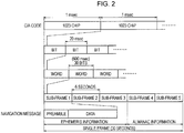
- Fig. 2 is an explanatory diagram illustrating a frame configuration of the navigation message.
- a single frame of the navigation message includes five sub-frames.
- the length of the single frame is 30 seconds, and has an amount of information of 1500 bits.
- Each sub-frame includes transmission time TOW of the navigation message.
- the first sub-frame 1 to third sub-frame 3 contains the ephemeris information on parameters for calculating factors such as a long radius of the orbit, an eccentricity, a mean anomaly, a longitude of ascending node, an argument of perigee, and an angle of orbit inclination.
- the fourth sub-frame 4 and fifth sub-frame 5 contain almanac information common to all the artificial satellites 10.
- the almanac information includes information on the six factors of all the artificial satellites 10, information as to which artificial satellite 10 is available, and the like.
- each sub-frame contains data following a preamble which is a fixed pattern.
- Each sub-frame includes ten words.
- the length of each sub-frame is six seconds, and has an amount of information of 300 bits.
- each word includes 30 bits, and the length thereof is 600 msec. Further, the length of each bit is 20 msec corresponding to 20 periods of the C/A code (the spreading code). Accordingly, the transmission rate of the data is 50 bps. Further, as shown in Fig. 2 , a single period of the C/A code is 1 msec, and the code includes 1023 chips of the PRN code.
- Fig. 3 is an explanatory diagram illustrating a hardware configuration of the receiver 20 according to the embodiment.
- the receiver 20 includes: a receiving section 210 having an antenna 212, a frequency converting section 220, a synchronization capturing section 240, and a synchronization holding section 250; a CPU (Central Processing Unit) 260; an RTC (Real Time Clock) 264; a timer 268; a memory 270; an XO (X'tal Oscillator) 272; a TCXO (Temperature Compensated X'tal Oscillator) 274; a multiplier/divider 276; and an acceleration sensor 280.
- a receiving section 210 having an antenna 212, a frequency converting section 220, a synchronization capturing section 240, and a synchronization holding section 250; a CPU (Central Processing Unit) 260; an RTC (Real Time Clock) 264; a timer 268; a memory 270; an
- the XO 272 oscillates a signal D1 having a predetermined frequency (for example, about 32.768 kHz), and provides the oscillated signal D1 to the RTC 264.
- the TCXO 274 oscillates a signal D2 having a frequency (for example, about 16.368 MHz) different from the XO 272, and provides the oscillated signal D2 to the multiplier/divider 276 or a frequency synthesizer 228.
- the multiplier/divider 276 performs multiplication, division, or both on the signal D2 provided from the TCXO 274 on the basis of an instruction from the CPU 260.
- the multiplier/divider 276 provides the signal D4 performed with multiplication, division, or both to the frequency synthesizer 228 of the frequency converting section 220, the CPU 260, the timer 268, the memory 270, the synchronization capturing section 240, and the synchronization holding section 250.
- the antenna 212 receives a radio signal (for example, an RF signal in which a carrier of 1575.42 MHz is spread out) such as the navigation message which is transmitted from the artificial satellite 10, converts the radio signal to an electric signal D5, and provides the electric signal D5 to the frequency converting section 220.
- a radio signal for example, an RF signal in which a carrier of 1575.42 MHz is spread out
- the frequency converting section 220 includes an LNA (Low Noise Amplifier) 222, a BPF (Band Pass Filter) 224, an amplifier 226, a frequency synthesizer 228, a multiplier 230, an amplifier 232, an LPF (Low Pass Filter) 234, and an ADC (Analog Digital Converter) 236.
- the frequency conversion section 220 down-converts the signal D5 having a high frequency of 1575.42 MHz received by the antenna 212 into the signal D14 having a frequency of, for example, about 1.023 MHz in order to facilitate the digital signal processing.
- the LNA 222 amplifies the signal D5 provided from the antenna 212, and provides the same to the BPF 224.
- the BPF 224 including a SAW filter (Surface Acoustic Wave Filter) extracts only a specific frequency component of the frequency components of the signal D6 amplified by the LNA, and provides the same to the amplifier 226.
- the amplifier 226 amplifies the signal D7 (a frequency F RF ) having the frequency component extracted by the BPF 224, and provides the same to the multiplier 230.
- the frequency synthesizer 228 generates a signal D10 having the frequency F LO on the basis of the instruction D9 from the CPU 260 by using the signal D2 provided from the TCXO 274.
- the frequency synthesizer 228 provides the generated signal D10 having the frequency F LO to the multiplier 230.
- the multiplier 230 multiples the signal D8 having the frequency F RF provided from the amplifier 226 and the signal D10 having the frequency F LO provided from the frequency synthesizer 228. That is, the multiplier 230 down-converts the high frequency signal into the IF (Intermediate Frequency) signal D11 (for example, an intermediate frequency signal having a frequency of about 1.023 MHz).
- IF Intermediate Frequency
- the amplifier 232 amplifies the IF signal D11 down-converted by the multiplier 230, and provides the same to the LPF 234.
- the LPF 234 extracts the low frequency component of the frequency components of the IF signal D12 amplified by the amplifier 232, and provides the signal D13 having the extracted low frequency component to the ADC 236.
- Fig. 3 shows an example in which the LPF 234 is disposed between the amplifier 232 and the ADC 236, but the BPF may be disposed between the amplifier 232 and the ADC 236.
- the ADC 236 converts the IF signal D13 of analog format provided from the LPF 234 to digital format, and provides the IF signal D14, which is converted to the digital format, to the synchronization capturing section 240 and the synchronization holding section 250.
- the synchronization capturing section 240 performs synchronization capturing of the PRN code of the IF signal D14, which is provided from the ADC 236, by using the signal D4, which is provided from the multiplier/divider 276, on the basis of the control by the CPU 260, and detects the carrier frequency of the IF signal D14.
- the synchronization capturing for example, an optional configuration such as a sliding correlator or a matched filter may be used. Then, the synchronization capturing section 240 provides the phase of the PRN code, the carrier frequency of the IF signal D14, and the like to the synchronization holding section 250 and the CPU 260.
- the synchronization holding section 250 performs synchronization holding of the PRN code and the carrier of the IF signal D14, which is provided from the ADC 236, by using the signal D4, which is provided from the multiplier/divider 276, on the basis of the control by the CPU 260. More specifically, the synchronization holding section 250 operates with the phase of the PRN code, the carrier frequency of the IF signal D14, and the like provided from the synchronization capturing section 240 as initial values. The synchronization holding section 250 demodulates the navigation message contained in the IF signal D14 which is provided from the ADC 236, and provides the same to the CPU 260.
- the CPU 260 calculates the position and speed of each artificial satellite 10 on the basis of the navigation message which is provided from the synchronization holding section 250, and calculates the position of the receiver 20.
- the CPU 260 corrects the time information of the RTC 264 on the basis of the navigation message, or performs various controls in connection with a control terminal, an I/O terminal, and an added function terminal.
- the CPU 260 according to the embodiment of the invention functions as a control section for controlling the loop order of the PLL 254 of the synchronization holding section 250.
- the RTC 264 measures a time by using the signal D1 having the predetermined frequency provided from the XO 272. The time measured by the RTC 264 is appropriately corrected by the CPU 260.
- the timer 268 keeps time by using the signal D4 which is provided from the multiplier/divider 276. Such timer 268 is referenced when determining the start timing of various controls performed by the CPU 260. For example, the CPU 260 references the timer 268 when determining the start timing of the operation of the PRN code generator of the synchronization holding section 250 on the basis of the PRN code which is captured by the synchronization capturing section 240.
- the memory 270 includes a RAM (Random Access Memory), a ROM (Read-Only Memory) and the like, and functions as a working space of the CPU 260, a storage section of a program, a storage section of the navigation message, and the like.
- the RAM is used as a working area for performing various processes performed by the CPU 260 and the like.
- the RAM is employed for buffering various data and for holding the ephemeris and almanac information as the orbit information of the artificial satellite 10 obtained from the synchronization holding section 250, intermediate data generated in the process of calculation, and result data of the calculation.
- the ROM is used as a section for storing various programs, fixed data, and the like.
- the nonvolatile memory may be used as a section for storing the ephemeris and almanac information as the orbit information of the artificial satellite 10, the position information of the position measurement result, an error amount of the TCXO 12, and the like, even when the power of the receiver 20 is off.
- the acceleration sensor 280 measures the acceleration of the receiver 20.
- the acceleration of the receiver 20 measured by the acceleration sensor 280 is provided to the CPU 260.
- a configuration excluding the XO 272, the TCXO 274, the antenna 212, the LNA 222, and the BPF 224 from the configuration of the receiver 20 shown in Fig. 3 can be made on an integrated circuit formed as a single chip.
- Fig. 4 is a flowchart illustrating the flow of the operation example of the receiver 20 according to the embodiment of the invention.
- the CPU 260 when the receiver 20 is activated, the CPU 260 performs an initial setting (S42). Subsequently, when one second is counted by the RTC 264 (S44), the CPU 260 allocates the artificial satellite 10 to each channel (S46).
- the CPU 260 selects at least four or more artificial satellites 10 to be actually used in position measurement calculation from the artificial satellites in which the synchronization holding is being performed (S50). Then, the CPU 260 calculates the current position and the speed of the selected artificial satellite 10 (S52), and calculates the current position and the speed of the receiver 20 on the basis of the calculated current position and the speed of the artificial satellite 10 (S54).
- the CPU 260 creates an output message representing the calculated current position and the speed of the receiver 20 (S56), and executes command processing corresponding to the output message, and the flow then returns to the processing of S44 (S58).
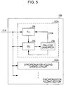
- Fig. 5 is an explanatory diagram illustrating the configuration of the synchronization holding section 250.
- the synchronization holding section 250 includes a plurality of synchronization holding channel circuits 252A, 252B.
- each synchronization holding channel circuit 252 performs the processing of the radio signal transmitted from the artificial satellite 10 of the satellite system 1.
- the synchronization holding section 250 including the plurality of synchronization holding channel circuits 252A, 252B ⁇ is able to perform parallel processing on radio signals which are transmitted from the plurality of artificial satellites 10.
- the synchronization holding channel circuit 252 includes a PLL (Phase-Locked Loop) 254, a DLL (Delay-locked Loop) 256, and a PRN code generator 258.
- PLL Phase-Locked Loop
- DLL Delay-locked Loop
- the PLL 254 performs the synchronization holding of the carrier of the IF signal D14 of the radio signal transmitted from the artificial satellite 10 of the satellite system 1, and outputs the carrier frequency of the artificial satellite 10 which is being tracked.
- the obtained carrier frequency is provided to the DLL 256, and is used in the position measurement. Further, the PLL 254 also extracts the navigation message, and the extracted navigation message is provided to the CPU 260.
- the DLL 256 performs the synchronization holding of the PRN code of the IF signal D14 of the radio signal transmitted from the artificial satellite 10 of the satellite system 1, and outputs the phase and the frequency of the PRN code of the artificial satellite 10 which is being tracked.
- the obtained PRN code phase is provided to the PLL 254, and is used in the position measurement.
- the PRN code frequency obtained by the DLL 256 is provided to the PRN code generator 258.
- the PRN code generator 258 generates the PRN code corresponding to the PRN code frequency obtained by the DLL 256.
- the type of the PRN code generated by the PRN code generator 258 is designated by the CPU 260 in accordance with the type of the artificial satellite 10 to be subjected to the synchronization holding.
- Fig. 6 is an explanatory diagram illustrating a detailed configuration of the PLL 254.
- the PLL 254 includes mixers 103, 104, and 105, LPFs 106 and 107, a phase detector 108, a loop filter 109, and an NCO 110.
- the mixer 103 multiplies a no-delay (Prompt or Punctual) signal of the PRN code, which is output from the PRN code generator 258, by the IF signal D14 provided from the ADC 236, and despreads the PRN code of the designated artificial satellite 10 included in the IF signal D14.
- the signal, which is despread by the mixer 103, is provided to the mixers 104 and 105.
- the mixer 104 multiplies the output of the mixer 103 and the cos component of the output of the NCO 110, thereby extracting an I component of the carrier of the radio signal in the process of tracking.
- the I component includes, as a frequency component, the sum and difference of the carrier frequency of the radio signal being in the process of tracking and the frequency of the carrier generated by the NCO 110. Further, the I component extracted by the mixer 104 is provided to the LPF 106.
- the mixer 105 multiplies the output of the mixer 103 and the sin component of the output of the NCO 110, thereby extracting a Q component of the carrier of the radio signal in the process of tracking from the output of the mixer 103.
- the Q component includes, as a frequency component, the sum and difference of the carrier frequency of the radio signal being in the process of tracking and the frequency of the carrier generated by the NCO 110. Further, the Q component extracted by the mixer 105 is provided to the LPF 107.
- the LPF 106 extracts the frequency component of the difference from the frequency component of the sum and difference of the frequencies of the carrier generated by the NCO 110 and the radio signal included in the output of the mixer 104.
- the frequency component extracted by the LPF 106 is provided to the phase detector 108.
- the LPF 107 extracts the frequency component of the different from the frequency component of the sum and difference of the frequencies of the carrier generated by the NCO 110 and the radio signal included in the output of the mixer 105.
- the frequency component extracted by the LPF 107 is provided to the phase detector 108.
- the LPFs 106 and 107 also have a function of removing out-of-band noise.
- the phase detector 108 detects the phase difference between the carrier of the radio signal being in the process of tracking and the carrier generated by the NCO 110 on the basis of the outputs of the LPFs 106 and 107.
- the phase difference information representing the phase difference detected by the phase detector 108 is provided to the loop filter 109.
- the loop filter 109 is an LPF for removing undesirable noise from the phase difference information and achieving desirable response of loop.
- the output of the loop filter 109 is provided to the NCO 110.
- a parameter specifying the response of loop in the loop filter 109 is acquired from the CPU 260.
- the NCO 110 generates a carrier signal corresponding to the frequency based on the input.
- the NCO 110 generates a reference carrier signal D101 and a signal D102 with a phase lag of 90 degrees.
- the carrier signal D101 generated by the NCO 110 is provided to the mixer 104, and the carrier signal D102 is provided to the mixer 105.
- the synchronization holding section 250 includes the PLL 254 for performing the synchronization holding of the carrier of the radio signal which is transmitted from the artificial satellite 10, and characteristics of the PLL 254 depend on the loop filter 109.
- a circuit configuration of a loop filter for a second-order PLL and a circuit configuration of a loop filter for a third-order PLL will be described with reference to Figs. 7 and 8 .
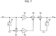
- Fig. 7 is an explanatory diagram illustrating an example of the circuit configuration of the loop filter for the second-order PLL.
- the circuit configuration of the loop filter for the second-order PLL includes delay elements 131 and 132, adders 141 to 143, and multipliers 121 and 122. Further, the multiplier 121 multiplies the input by B, and the multiplier 122 multiplies the input by A.
- the loop filter for the second-order PLL having such a circuit configuration is expressed by the following differential equation of Numerical Expression 1.
- the latest output from the phase detector 108 is defined as the input x n
- the previous output from the phase detector 108 is defined as the input x n-1
- the latest output from the loop filter shown in Fig. 7 is defined as the output y n
- the previous output from the loop filter shown in Fig. 7 is defined as the output y n-1
- the A and B are coefficients multiplied by the multiplier 122 and multiplier 121, and are parameters for determining characteristics of the PLL.
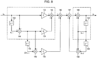
- Fig. 8 is an explanatory diagram illustrating an example of the circuit configuration of the loop filter for the third-order PLL.
- the circuit configuration of the loop filter for the third-order PLL includes delay elements 133 to 136, adders 144 to 150, and multipliers 123 to 125. Further, the multiplier 123 multiplies the input by E, the multiplier 124 multiplies the input by D, and the multiplier 125 multiplies the input by C.
- the loop filter for the third-order PLL having such a circuit configuration is expressed by the following differential equation of Numerical Expression 2.
- y n y n ⁇ 1 + ⁇ y n ⁇ 1 + C ⁇ x n + D ⁇ x n + E x n , where
- phase errors occur under the condition of accelerated motion (its tracking ability under acceleration is low), but its loop stability is high (it has high resistance to noise).
- the third-order PLL its tracking ability under acceleration is high, but its loop stability is lower than that of the second-order PLL (it has low resistance to noise).
- the PLLs should be selectively used as the situation demands.
- the circuit configuration of the loop filter for the second-order PLL and the circuit configuration of the loop filter for the third-order PLL are separately provided, a problem arises in that the size of the circuit increases.
- the PLL 254 according to the embodiment of the invention has been made.
- the PLL 254 according to the embodiment of the invention it is possible to change the order of the loop while suppressing an increase in size of the circuit.
- the loop filter 109 for embodying the PLL 254 will be described in detail.
- the circuit configuration of the loop filter for the third-order PLL includes the circuit configuration of the loop filter for the second-order PLL. More specifically, the circuit configuration in the area enclosed by the dotted line in Fig. 8 corresponds to the circuit configuration of the loop filter for the second-order PLL. Accordingly, as an embodiment of the invention, a loop filter having a circuit configuration shown in Fig. 9 is proposed in view of the above.
- Fig. 9 is an explanatory diagram illustrating the circuit configuration of the loop filter 109 according to the embodiment of the invention.
- the loop filter 109 according to the embodiment of the invention includes delay elements 301 to 304 constituted by storage elements such as registers and RAMs, adders 305 to 311, multipliers 126 to 128, and switches S01.
- the delay element 301 and the adder 305 are components for obtaining ⁇ x n in Numerical Expression 1 and Numerical Expression 2. Specifically, the delay element 301 retains x n-1 , and the adder 305 subtracts x n-1 , which is retained in the delay element 301, from x n , thereby obtaining ⁇ x n .
- the delay element 302 and the adder 306 are components for obtaining ⁇ x n in Numerical Expression 2. Specifically, the delay element 302 retains ⁇ x n-1 , and the adder 306 subtracts ⁇ x n-1 , which is retained in the delay element 302, from ⁇ x n , thereby obtaining ⁇ x n .
- the delay element 303 is a component for obtaining y n-1 in Numerical Expression 1 and Numerical Expression 2. Specifically, the delay element 303 retains y n-1 .
- the delay element 304 and the adder 311 are components for obtaining ⁇ y n-1 in Numerical Expression 2. Specifically, the delay element 304 retains y n-2 , and the adder 311 subtracts y n-2 , which is retained in the delay element 304, from y n-1 , thereby obtaining ⁇ y n-1 .
- the multiplier 126 is a component for obtaining Bx n in Numerical Expression 1 or Ex n in Numerical Expression 2. Specifically, the multiplier 126 multiplies x n by the parameter B or E, thereby obtaining Bx n in Numerical Expression 1 or Ex n in Numerical Expression 2.
- the multiplier 127 is a component for obtaining A ⁇ x n in Numerical Expression 1 or D ⁇ x n in Numerical Expression 2. Specifically, the multiplier 127 multiplies ⁇ x n , which is output from the adder 305, by the parameter A or D, thereby obtaining A ⁇ x n in Numerical Expression 1 or D ⁇ x n in Numerical Expression 2.
- the multiplier 128 is a component for obtaining C ⁇ x n in Numerical Expression 2. Specifically, the multiplier 128 multiplies ⁇ x n , which is output from the adder 306, by the parameter C, thereby obtaining C ⁇ x n in Numerical Expression 2.
- multipliers 126 to 128 may be configured as bit shifters.
- n is an integer, and n ⁇ 0
- n-bit left shift is realized by n-bit left shift.
- n-bit right shift is realized by n-bit right shift.
- the multipliers 126 to 128 are configured as bit shifters, and thus it is possible to reduce the size of the circuit.
- a multiplier factor which can be set is restricted, and thus it is important to inspect the design thereof previously.
- the adder 307 adds A ⁇ x n and Bx n in Numerical Expression 1, and adds D ⁇ x n and Ex n in Numerical Expression 2.
- the adder 308 adds C ⁇ x n in Numerical Expression 2 to the added value obtained by allowing the adder 307 to add D ⁇ x n and Ex n .
- the adder 309 adds ⁇ y n-1 obtained by the adder 311 in Numerical Expression 2 to the output from the adder 308.
- the adder 310 adds y n-1 , which is retained in the delay element 303, to the output from the adder 309 when the switch S01 is connected to the adder 309 through the terminal A.
- the adder 310 adds y n-1 , which is retained in the delay element 303, to the output from the adder 307 when the switch S01 is connected to the adder 307 through the terminal B.
- switch S01 switching section
- the switch S01 switching section
- the switch S01 is connected to the adder 310, and the other end thereof is connected to the adder 309 through the terminal A or the adder 307 through the terminal B. Furthermore, the connection between the switch S01 and the terminal A or B to be described later in detail is controlled by the CPU 260 on the basis of the reception intensity of the radio signal and the current state of the receiver 20 such as the acceleration of the receiver 20.
- the above-mentioned loop filter 109 is formed by adding the switch S01 and the terminals A and B to the circuit configuration of the loop filter for the third-order PLL shown in Fig. 8 .
- the loop filter 109 is configured so that the entirety of the circuit configuration of the loop filter for the third-order PLL is activated when the switch S01 is connected to the terminal A, and thus can be operated as the loop filter for the third-order PLL.
- the loop order of the PLL 254 becomes the third order.
- the circuit configuration in the area enclosed by the dotted line in Fig. 9 corresponds to the circuit configuration of the loop filter for the second-order PLL as shown in Fig. 7 .
- the loop filter 109 is configured so that the entirety of the circuit configuration of the loop filter for the second-order PLL is activated when the switch S01 is connected to the terminal B, and thus can be operated as the loop filter for the second-order PLL.
- the loop order of the PLL 254 becomes the second order.
- the output from the loop filter 109 depends on the processing in the activated circuit configuration, and does not depend on the inactivated circuit configuration.
- the PLL 254 has performance in synchronization holding, that is, tracking in accordance with the loop order. For example, when the loop order of the PLL 254 is 2 (when the switch S01 is connected to the terminal B), the acceleration tracking ability is low, but the resistance to noise is high. On the other hand, when the loop order of the PLL 254 is 3 (when the switch S01 is connected to the terminal A), the acceleration tracking ability is high, but the resistance to noise is low.
- the CPU 260 changes over the parameters multiplied by the multiplier 126 to 128 in conjunction with the changeover of the switch S01. Further, in the embodiment of the invention, the example in which the changeover is performed by software is described, but the changeover may be performed by hardware.
- the loop filter 109 according to the embodiment of the invention can be configured to suppress an increase in size of the circuit, as compared with the case where the circuit configurations of the loop filters for the second-order PLL and the third-order PLL are separately combined.
- the sizes of the circuit configuration for the second-order PLL, the circuit configuration for the third-order PLL, the circuit configuration in which both of the configurations are separately combined, and the circuit configuration according to the embodiment of the invention are compared in detail with each other.
- the loop filter 109 capable of switching the loop order of the PLL 254 between the second order and the third order can be formed to have a size equal to that of the circuit configuration of the loop filter for the third-order PLL. Furthermore, when the circuit configuration for the second-order PLL and the circuit configuration for the third-order PLL are separately combined, a wiring area for connecting both circuit configurations is also necessary. Therefore, according to the embodiment of the invention, an effect that reduces the number of the calculator is obtained.
- the changeover of the switch S01 in the above-mentioned loop filter 109 is controlled by the CPU 260 in accordance with the current state of the receiver 20.
- the control method of the loop filter 109 performed by the CPU 260 will be described in detail.
- the CPU 260 controls the changeover of the switch S01 on the basis of the signal intensity of the reception signal transmitted from the artificial satellite 10.
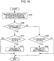
- the control method according to the first example will be described with reference to Fig. 10 .
- Fig. 10 is a flowchart illustrating a flow of the control method according to the first example of the loop filter 109.
- the signal intensity L of the reception signal in the process of tracking is measured (S404).
- the measurement of the signal intensity L corresponds to, for example, the processing in the LPF 106. That is, in the embodiment of the invention, the output from the LPF 106 may be treated as the signal intensity L of the reception signal, and the average value of the output from the LPF 106 may be treated as the signal intensity L of the reception signal. Furthermore, according to the embodiment of the invention, the average value of the square sum of the output (I component) from the LPF 106 and the output (Q component) from the LPF 107 may be treated as the signal intensity L of the reception signal.
- the CPU 260 determines whether or not the signal intensity L is less than a threshold value M (S412). Then, when the signal intensity L is less than the threshold value M, the CPU 260 changes the connection place of the switch S01 to the terminal B, thereby changing the loop order of the PLL 254 into the second order (S416).
- the threshold value M is stored in the ROM of the memory 270.
- the CPU 260 copies the threshold value M, which is stored in the ROM at the time of activation, to a specific area of the RAM of the memory 270, thereby referring to the specific area at the time of comparing the signal intensity L with the threshold value M. Further, the CPU 260 is able to change dynamically the threshold value M in the process of the tracking operation.
- the CPU 260 determines whether or not the signal intensity L is the threshold value M or more (S420). Then, when the signal intensity L is the threshold value M or more, the CPU 260 changes the connection place of the switch S01 to the terminal A, thereby changing the loop order of the PLL 254 into the third order (S424).
- the CPU 260 may compare the signal intensity L shown in the above-mentioned steps S412 or S420 with the threshold value M at a predetermined interval of 1 msec or 20 msec.
- the PLL 254 performs the synchronization holding using the third-order PLL on the basis of the control performed by the CPU 260. Therefore, it is possible to improve the acceleration tracking ability.
- the signal intensity L is less than the threshold value M
- the PLL 254 performs the synchronization holding using the second-order PLL on the basis of the control performed by the CPU 260. Therefore, it is possible to improve the receiver sensitivity.
- the threshold value M increase, a rate of operation of the PLL 254 as the third-order PLL increases, and a rate of operation of the PLL 254 as the second-order PLL increases. Therefore, it becomes difficult to improve the acceleration tracking ability.
- the threshold value M is set to be excessively low, the tracking is likely to fail because of the effect of the noise while the PLL 254 is operated as the third-order PLL. Accordingly, it is effective that the threshold value M is set to be as low as possible in the range of the signal intensity in which the PLL 254 operated as the third-order PLL is able to perform the tracking.
- the CPU 260 controls the changeover of the switch S01 on the basis of the acceleration of the receiver 20 measured by the acceleration sensor 280.
- the control method according to the second example will be described with reference to Fig. 11 .
- Fig. 11 is a flowchart illustrating a flow of the control method according to the second example of the loop filter 109.
- the acceleration a of the receiver 20 is measured by the acceleration sensor 280 (S504).
- the average value of the acceleration measured by the acceleration sensor 280 is treated as the acceleration a.
- the CPU 260 determines whether or not the absolute value of the acceleration a is less than a threshold value N (S512). Then, when the absolute value of the acceleration a is less than the threshold value N, the CPU 260 changes the connection place of the switch S01 to the terminal B, thereby changing the loop order of the PLL 254 into the second order (S516).
- the threshold value N is stored in the ROM of the memory 270.
- the CPU 260 copies the threshold value N, which is stored in the ROM at the time of activation, to a specific area of the RAM of the memory 270, thereby referring to the specific area at the time of comparing the absolute value of the acceleration a with the threshold value N. Further, the CPU 260 is able to change dynamically the threshold value N in the process of the tracking operation.
- the CPU 260 determines whether or not the absolute value of the acceleration a is the threshold value N or more (S520). Then, when the absolute value of the acceleration a is the threshold value N or more, the CPU 260 changes the connection place of the switch S01 to the terminal A, thereby changing the loop order of the PLL 254 into the third order (S524).
- the CPU 260 may compare the absolute value of the acceleration a shown in the above-mentioned steps S512 or S520 with the threshold value N at a predetermined interval of 1 msec or 20 msec.
- the PLL 254 performs the synchronization holding using the third-order PLL on the basis of the control performed by the CPU 260. Therefore, it is possible to improve the acceleration tracking ability. More specifically, a vehicle equipped with the receiver 20 enters the curve, an increase in the acceleration a changes the order of the PLL 254 to the third order, and thus it is expected to improve the acceleration tracking ability.
- the absolute value of the acceleration a is less than the threshold value N, the PLL 254 performs the synchronization holding using the second-order PLL on the basis of the control performed by the CPU 260. Therefore, it is possible to improve the receiver sensitivity.
- the threshold value N increase, a rate of operation of the PLL 254 as the third-order PLL increases, and a rate of operation of the PLL 254 as the second-order PLL increases. Therefore, it becomes difficult to improve the acceleration tracking ability.
- the threshold value N is set to be excessively low, the tracking is likely to fail because of the effect of the noise while the PLL 254 is operated as the third-order PLL. Accordingly, it is effective that the threshold value N is set to be as low as possible in the range of the acceleration a in which the PLL 254 operated as the third-order PLL is able to perform the tracking.
- the PLL 254 by changing the loop order of the PLL 254 in accordance with the current state of the receiver 20, it is possible to exhibit advantages of the second-order PLL and the third-order PLL.
- the PLL 254 performs the synchronization holding using the third-order PLL on the basis of the control performed by the CPU 260. Therefore, it is possible to improve the acceleration tracking ability.
- the signal intensity L is less than the threshold value M, the PLL 254 performs the synchronization holding using the second-order PLL on the basis of the control performed by the CPU 260. Therefore, it is possible to improve the receiver sensitivity.
- the loop filter 109 capable of switching the loop order of the PLL 254 between the second order and the third order can be formed to have a size equal to that of the circuit configuration of the loop filter for the third-order PLL. Furthermore, when the circuit configuration for the second-order PLL and the circuit configuration for the third-order PLL are separately combined, a wiring area for connecting both circuit configurations is also necessary. Therefore, according to the embodiment of the invention, the effect that reduces the number of the calculator is obtained. Furthermore, according to the embodiment of the invention, it is possible to reduce power consumption.
- the acceleration of the apparatus equipped with the receiver 20 may be set to be low, and the threshold value M or N may be set to be high.
- the PLL 254 is often operated as the second-order PLL, it is possible to exhibit the stability which is an advantage of the second-order PLL.
- the threshold value M or N may be set to be low.
- the PLL 254 is often operated as the third-order PLL, it is possible to exhibit the acceleration tracking ability which is an advantage of the third-order PLL.
- the steps in the processing of the receiver 20 in the description may include the processing (for example, parallel processing or processing performed by an object) performed separately or in parallel.
- the description gives examples of changing the loop order of the PLL 254 into the second order and the third order, but the invention is not limited to the examples.
- the circuit configuration for the m-th order PLL including the circuit configuration for the n-th order PLL (m>n) is provided in the loop filter 109, and the which circuit configuration is activated is changed by the switch S01, and thereby it is possible to change the loop order of the PLL 254 between the n-th order and m-th order.
- the above description gives an example of using the signal intensity L or the acceleration a in the change of the loop order of the PLL 254, but the invention is not limited to the example.
- both of the signal intensity L and acceleration a may be used in the change of the loop order of the PLL 254 in a combined manner.
Landscapes
- Engineering & Computer Science (AREA)
- Physics & Mathematics (AREA)
- Computer Hardware Design (AREA)
- Mathematical Physics (AREA)
- Radar, Positioning & Navigation (AREA)
- Remote Sensing (AREA)
- Computer Networks & Wireless Communication (AREA)
- General Physics & Mathematics (AREA)
- Position Fixing By Use Of Radio Waves (AREA)
- Stabilization Of Oscillater, Synchronisation, Frequency Synthesizers (AREA)
Claims (9)
- Phasenregelschleife, umfassend:ein Schleifenfilter, das eine Schaltungsanordnung m für eine Phasenregelschleife m-ter Ordnung aufweist, die eine Schaltungsanordnung n für eine Phasenregelschleife n-ter Ordnung aufweist (m>n); undeinen Schaltabschnitt zum Umschalten der Schaltungsanordnungen, die im Schleifenfilter aktiviert sind, zwischen der Schaltungsanordnung n und der Schaltungsanordnung m,wobei der Schaltabschnitt nur einen Schalter zum Umschalten zwischen den beiden Schaltungsanordnungen umfasst, wobei die Schaltungsanordnung n durch die Differentialgleichung yn=yn- 1+AΔxn+Bxn beschrieben wird und die Schaltungsanordnung m durch die Differentialgleichung

ΔXn=xn-xn-1, Δyn=yn-1-yn-2, δxn=Δxn-Δxn-1=(xn-xn-1)-(xn-1 -xn-2 ),
wobei A, B, C, D und E Multiplikationsfaktoren sind, xn das Stromeingangssignal des Filters darstellt und yn das Stromausgangssignal des Filters darstellt; und wobei die Schaltungsanordnung n dieselben Schaltungen verwendet wie die Schaltungsanordnung m. - Kommunikationssystem, das eine Phasenregelschleife gemäß Anspruch 1 umfasst, welche die Synchronisation eines Empfangssignals erhält.
- Kommunikationssystem gemäß Anspruch 2, das ferner einen Steuerabschnitt umfasst, welcher dafür ausgelegt ist, in Reaktion auf eine Änderung eines Stromzustands des Kommunikationssystems den Schaltabschnitt so zu steuern, dass die Schaltungsanordnungen umgeschaltet werden.
- Kommunikationssystem gemäß Anspruch 3, wobei der Steuerabschnitt dafür ausgelegt ist,
einen Schwellwert mit einem Wert zu vergleichen, der basierend auf einer Signalintensitätsmessung des Empfangssignals erhalten wird,
den Schaltabschnitt so zu steuern, dass die Schaltungsanordnungen, die im Schleifenfilter aktiviert sind, von der Schaltungsanordnung n auf die Schaltungsanordnung m umgeschaltet werden, wenn der Wert gleich dem Schwellwert oder größer ist, und
den Schaltabschnitt so zu steuern, dass die Schaltungsanordnungen, die im Schleifenfilter aktiviert sind, von der Schaltungsanordnung m auf die Schaltungsanordnung n umgeschaltet werden, wenn der Wert kleiner als der Schwellwert ist. - Kommunikationssystem gemäß Anspruch 4, wobei der Steuerabschnitt dafür ausgelegt ist, periodisch den Schwellwert mit dem Wert zu vergleichen, der basierend auf der Signalintensitätsmessung des Empfangssignals erhalten wird.
- Kommunikationssystem gemäß Anspruch 3, wobei der Steuerabschnitt dafür ausgelegt ist,
einen Schwellwert mit einem Wert zu vergleichen, welcher basierend auf einer Beschleunigungsmessung des Kommunikationssystems erhalten wird, wobei die Beschleunigungsmessung durch einen Empfänger durchgeführt wird, der seine Beschleunigung misst und Teil des Kommunikationssystems ist,
den Schaltabschnitt so zu steuern, dass die Schaltungsanordnungen, die im Schleifenfilter aktiviert sind, von der Schaltungsanordnung m auf die Schaltungsanordnung n umgeschaltet werden, wenn der Wert gleich dem Schwellwert oder größer ist, und
den Schaltabschnitt so zu steuern, dass die Schaltungsanordnungen, die im Schleifenfilter aktiviert sind, von der Schaltungsanordnung n auf die Schaltungsanordnung m umgeschaltet werden, wenn der Wert kleiner als der Schwellwert ist. - Kommunikationssystem gemäß Anspruch 6, wobei der Steuerabschnitt dafür ausgelegt ist, periodisch den Schwellwert mit dem Wert zu vergleichen, der basierend auf der Beschleunigungsmessung des Kommunikationssystems erhalten wird.
- Beweglicher Körper, der mit einem Kommunikationssystem gemäß einem der Ansprüche 2 bis 7 ausgerüstet ist.
- Verfahren, das in einem Schleifenfilter ausgeführt wird, das in einer Phasenregelschleife zum Erhalten der Synchronisation eines Empfangssignals enthalten ist und eine Schaltungsanordnung m für eine Phasenregelschleife m-ter Ordnung besitzt, die eine Schaltungsanordnung n für eine Phasenregelschleife n-ter Ordnung aufweist (m>n), wobei das Verfahren einen Schritt des Umschaltens der aktivierten Schaltungsanordnungen zwischen der Schaltungsanordnung n und der Schaltungsanordnung m umfasst,
wobei der Schaltabschnitt nur einen Schalter zum Umschalten zwischen den beiden Schaltungsanordnungen umfasst, wobei die Schaltungsanordnung n durch die Formel yn=yn- 1+AΔxn+Bxn beschrieben wird und die Schaltungsanordnung m durch die Formel
Δxn=xn-xn-1, Δyn=yn-1-yn-2, δxn=Δxn -Δxn-1=(xn-xn-1)-(xn-1-xn-2),
wobei A, B, C, D und E Multiplikationsfaktoren sind, xn das Stromeingangssignal des Filters darstellt und yn das Stromausgangssignal des Filters darstellt; und wobei die Schaltungsanordnung n dieselben Schaltungen verwendet wie die Schaltungsanordnung m.
Applications Claiming Priority (1)
| Application Number | Priority Date | Filing Date | Title |
|---|---|---|---|
| JP2009089395A JP5262932B2 (ja) | 2009-04-01 | 2009-04-01 | 通信装置、位相同期ループ、移動体および通信方法 |
Publications (2)
| Publication Number | Publication Date |
|---|---|
| EP2237422A1 EP2237422A1 (de) | 2010-10-06 |
| EP2237422B1 true EP2237422B1 (de) | 2017-08-02 |
Family
ID=42138776
Family Applications (1)
| Application Number | Title | Priority Date | Filing Date |
|---|---|---|---|
| EP10157737.7A Not-in-force EP2237422B1 (de) | 2009-04-01 | 2010-03-25 | Phasenregelschleife mit variabeler ordnung und rekonfigurierbaren Schleifenfilter und ihre Anwendung in einem GPS-Empfänger |
Country Status (3)
| Country | Link |
|---|---|
| US (1) | US8222935B2 (de) |
| EP (1) | EP2237422B1 (de) |
| JP (1) | JP5262932B2 (de) |
Families Citing this family (14)
| Publication number | Priority date | Publication date | Assignee | Title |
|---|---|---|---|---|
| JP5262932B2 (ja) * | 2009-04-01 | 2013-08-14 | ソニー株式会社 | 通信装置、位相同期ループ、移動体および通信方法 |
| JP2010252094A (ja) * | 2009-04-16 | 2010-11-04 | Renesas Electronics Corp | Pll回路 |
| JP5696777B2 (ja) * | 2011-03-01 | 2015-04-08 | 富士通株式会社 | クロックジェネレータ及びそれを含むシステム |
| FR2972810B1 (fr) * | 2011-03-16 | 2014-01-03 | Sagem Defense Securite | Detection et correction d'incoherence de phase porteuse en poursuite d'un signal de radionavigation |
| CN103167079B (zh) * | 2012-09-14 | 2015-08-05 | 深圳市金立通信设备有限公司 | 一种手机测量系统及方法 |
| US9385767B2 (en) * | 2013-05-28 | 2016-07-05 | Topcon Positioning Systems, Inc. | Apparatus for correcting multipath errors in carrier phase measurements of a navigation receiver |
| CN104158553B (zh) * | 2014-08-28 | 2017-03-08 | 上海航天电子通讯设备研究所 | 一种锁相接收机混合环路 |
| US9385729B1 (en) * | 2015-12-21 | 2016-07-05 | International Business Machines Corporation | System and method for controlling a phase lock loop |
| US9705512B1 (en) * | 2016-09-20 | 2017-07-11 | Realtek Semiconductor Corporation | Self-calibrating fractional-N phase lock loop and method thereof |
| JP2018056674A (ja) | 2016-09-27 | 2018-04-05 | セイコーエプソン株式会社 | 回路装置、物理量測定装置、電子機器及び移動体 |
| JP6834299B2 (ja) | 2016-09-27 | 2021-02-24 | セイコーエプソン株式会社 | 回路装置、物理量測定装置、電子機器及び移動体 |
| CN107870556B (zh) | 2016-09-27 | 2021-08-17 | 精工爱普生株式会社 | 集成电路装置、电子设备和移动体 |
| JP2018056673A (ja) * | 2016-09-27 | 2018-04-05 | セイコーエプソン株式会社 | 回路装置、物理量測定装置、電子機器及び移動体 |
| US10886877B2 (en) * | 2018-12-18 | 2021-01-05 | Viasat, Inc. | Adaptive microphonics noise cancellation |
Family Cites Families (13)
| Publication number | Priority date | Publication date | Assignee | Title |
|---|---|---|---|---|
| US4855689A (en) * | 1987-02-13 | 1989-08-08 | Hughes Aircraft Company | Phase lock loop with switchable filter for acquisition and tracking modes |
| US6353408B1 (en) | 1998-03-31 | 2002-03-05 | U.S. Philips Corporation | Electronic navigation apparatus |
| US6366144B2 (en) | 1999-11-30 | 2002-04-02 | Samsung Electronics Co., Ltd. | Loop filtering apparatus for reducing frequency lock-up time and phase noise of a phase locked loop for use in a mobile terminal |
| JP2003198650A (ja) * | 2001-12-26 | 2003-07-11 | Matsushita Electric Ind Co Ltd | 同期検波装置および同期検波方法 |
| US7277519B2 (en) * | 2003-12-02 | 2007-10-02 | Texas Instruments Incorporated | Frequency and phase correction in a phase-locked loop (PLL) |
| US7298221B2 (en) * | 2005-02-22 | 2007-11-20 | Integrated Device Technology, Inc. | Phase-locked loop circuits with current mode loop filters |
| WO2006137031A2 (en) * | 2005-06-21 | 2006-12-28 | Nxp B.V. | Phase-locked loop systems using adaptive low-pass filters in switched bandwidth feedback loops |
| SG141260A1 (en) * | 2006-09-12 | 2008-04-28 | Oki Techno Ct Singapore Pte | An apparatus, a receiver and a method for timing recovery in an ofdm system |
| US8265652B2 (en) | 2007-10-02 | 2012-09-11 | Ricoh Co., Ltd. | Geographic tagging of network access points |
| US8295798B2 (en) * | 2008-10-20 | 2012-10-23 | Qualcomm, Incorporated | Tunable filters with lower residual sideband |
| US7994870B2 (en) * | 2008-10-20 | 2011-08-09 | Qualcomm, Incorporated | Tunable filter with gain control circuit |
| JP5262932B2 (ja) * | 2009-04-01 | 2013-08-14 | ソニー株式会社 | 通信装置、位相同期ループ、移動体および通信方法 |
| US8779973B2 (en) * | 2010-02-08 | 2014-07-15 | Seiko Epson Corporation | Satellite signal tracking method, position calculating method, and position calculating device |
-
2009
- 2009-04-01 JP JP2009089395A patent/JP5262932B2/ja not_active Expired - Fee Related
-
2010
- 2010-02-26 US US12/713,798 patent/US8222935B2/en not_active Expired - Fee Related
- 2010-03-25 EP EP10157737.7A patent/EP2237422B1/de not_active Not-in-force
Non-Patent Citations (1)
| Title |
|---|
| None * |
Also Published As
| Publication number | Publication date |
|---|---|
| EP2237422A1 (de) | 2010-10-06 |
| JP2010245635A (ja) | 2010-10-28 |
| US20100253402A1 (en) | 2010-10-07 |
| JP5262932B2 (ja) | 2013-08-14 |
| US8222935B2 (en) | 2012-07-17 |
Similar Documents
| Publication | Publication Date | Title |
|---|---|---|
| US8222935B2 (en) | Communication system, phase-locked loop, movable body and communication method | |
| US8599904B2 (en) | Method and apparatus for software GPS receiver | |
| EP1169653B1 (de) | Signaldetektor mit verwendung von kohärenterintegration | |
| US9075139B2 (en) | Satellite signal tracking method and receiver | |
| JP5310333B2 (ja) | 受信装置、信号処理方法、およびプログラム | |
| WO2006121712A2 (en) | Efficient and flexible gps receiver baseband architecture | |
| US7085309B2 (en) | Radiofrequency signal receiver with means for correcting the effects of multipath signals, and method for activating the receiver | |
| JP5982991B2 (ja) | 受信部駆動制御方法及び受信装置 | |
| US8779973B2 (en) | Satellite signal tracking method, position calculating method, and position calculating device | |
| JP2009002659A (ja) | コヒーレント積算増進回路、測位回路、電子機器、コヒーレント積算増進方法、測位方法、プログラム、及び記憶媒体 | |
| JP5029190B2 (ja) | 受信回路、電子機器及びノイズキャンセル方法 | |
| US8953721B2 (en) | Cross correlation determination method and cross correlation determination device | |
| US7633440B2 (en) | Positioning receiver | |
| US8249202B2 (en) | Communication system, signal processing method, signal processing device, and movable body | |
| JP2011117830A (ja) | Gnss受信装置及び測位方法 | |
| JP2009005151A (ja) | ベースバンド信号処理回路、受信システム及びベースバンド信号処理方法 | |
| EP2284573B1 (de) | Signalempfänger, Steuerungsverfahren des Signalempfängers, GPS-Vorrichtung mit dem Signalempfänger und Verfahren | |
| JP4137623B2 (ja) | 汎用prn符号発生回路および汎用測位用受信機 | |
| JP4888110B2 (ja) | 相関演算制御回路及び相関演算制御方法 | |
| EP1903346A1 (de) | Speicherverringerung in GNSS-Empfängern | |
| JP6326767B2 (ja) | 測位用衛星信号受信方法、測位用衛星信号受信装置及び電子機器 | |
| WO2009044205A2 (en) | Correlator for global navigation satellite systems | |
| CN121008298A (zh) | 全球卫星导航系统的多普勒补偿装置及方法 | |
| JP6269716B2 (ja) | 受信部駆動制御方法及び受信装置 |
Legal Events
| Date | Code | Title | Description |
|---|---|---|---|
| PUAI | Public reference made under article 153(3) epc to a published international application that has entered the european phase |
Free format text: ORIGINAL CODE: 0009012 |
|
| 17P | Request for examination filed |
Effective date: 20100325 |
|
| AK | Designated contracting states |
Kind code of ref document: A1 Designated state(s): AT BE BG CH CY CZ DE DK EE ES FI FR GB GR HR HU IE IS IT LI LT LU LV MC MK MT NL NO PL PT RO SE SI SK SM TR |
|
| AX | Request for extension of the european patent |
Extension state: AL BA ME RS |
|
| GRAP | Despatch of communication of intention to grant a patent |
Free format text: ORIGINAL CODE: EPIDOSNIGR1 |
|
| INTG | Intention to grant announced |
Effective date: 20170223 |
|
| GRAS | Grant fee paid |
Free format text: ORIGINAL CODE: EPIDOSNIGR3 |
|
| GRAA | (expected) grant |
Free format text: ORIGINAL CODE: 0009210 |
|
| AK | Designated contracting states |
Kind code of ref document: B1 Designated state(s): AT BE BG CH CY CZ DE DK EE ES FI FR GB GR HR HU IE IS IT LI LT LU LV MC MK MT NL NO PL PT RO SE SI SK SM TR |
|
| REG | Reference to a national code |
Ref country code: GB Ref legal event code: FG4D |
|
| REG | Reference to a national code |
Ref country code: CH Ref legal event code: EP Ref country code: AT Ref legal event code: REF Ref document number: 915495 Country of ref document: AT Kind code of ref document: T Effective date: 20170815 |
|
| REG | Reference to a national code |
Ref country code: IE Ref legal event code: FG4D |
|
| REG | Reference to a national code |
Ref country code: DE Ref legal event code: R096 Ref document number: 602010044006 Country of ref document: DE |
|
| REG | Reference to a national code |
Ref country code: NL Ref legal event code: MP Effective date: 20170802 |
|
| REG | Reference to a national code |
Ref country code: AT Ref legal event code: MK05 Ref document number: 915495 Country of ref document: AT Kind code of ref document: T Effective date: 20170802 |
|
| REG | Reference to a national code |
Ref country code: LT Ref legal event code: MG4D |
|
| PG25 | Lapsed in a contracting state [announced via postgrant information from national office to epo] |
Ref country code: NL Free format text: LAPSE BECAUSE OF FAILURE TO SUBMIT A TRANSLATION OF THE DESCRIPTION OR TO PAY THE FEE WITHIN THE PRESCRIBED TIME-LIMIT Effective date: 20170802 Ref country code: AT Free format text: LAPSE BECAUSE OF FAILURE TO SUBMIT A TRANSLATION OF THE DESCRIPTION OR TO PAY THE FEE WITHIN THE PRESCRIBED TIME-LIMIT Effective date: 20170802 Ref country code: LT Free format text: LAPSE BECAUSE OF FAILURE TO SUBMIT A TRANSLATION OF THE DESCRIPTION OR TO PAY THE FEE WITHIN THE PRESCRIBED TIME-LIMIT Effective date: 20170802 Ref country code: SE Free format text: LAPSE BECAUSE OF FAILURE TO SUBMIT A TRANSLATION OF THE DESCRIPTION OR TO PAY THE FEE WITHIN THE PRESCRIBED TIME-LIMIT Effective date: 20170802 Ref country code: FI Free format text: LAPSE BECAUSE OF FAILURE TO SUBMIT A TRANSLATION OF THE DESCRIPTION OR TO PAY THE FEE WITHIN THE PRESCRIBED TIME-LIMIT Effective date: 20170802 Ref country code: NO Free format text: LAPSE BECAUSE OF FAILURE TO SUBMIT A TRANSLATION OF THE DESCRIPTION OR TO PAY THE FEE WITHIN THE PRESCRIBED TIME-LIMIT Effective date: 20171102 Ref country code: HR Free format text: LAPSE BECAUSE OF FAILURE TO SUBMIT A TRANSLATION OF THE DESCRIPTION OR TO PAY THE FEE WITHIN THE PRESCRIBED TIME-LIMIT Effective date: 20170802 |
|
| PG25 | Lapsed in a contracting state [announced via postgrant information from national office to epo] |
Ref country code: IS Free format text: LAPSE BECAUSE OF FAILURE TO SUBMIT A TRANSLATION OF THE DESCRIPTION OR TO PAY THE FEE WITHIN THE PRESCRIBED TIME-LIMIT Effective date: 20171202 Ref country code: BG Free format text: LAPSE BECAUSE OF FAILURE TO SUBMIT A TRANSLATION OF THE DESCRIPTION OR TO PAY THE FEE WITHIN THE PRESCRIBED TIME-LIMIT Effective date: 20171102 Ref country code: GR Free format text: LAPSE BECAUSE OF FAILURE TO SUBMIT A TRANSLATION OF THE DESCRIPTION OR TO PAY THE FEE WITHIN THE PRESCRIBED TIME-LIMIT Effective date: 20171103 Ref country code: ES Free format text: LAPSE BECAUSE OF FAILURE TO SUBMIT A TRANSLATION OF THE DESCRIPTION OR TO PAY THE FEE WITHIN THE PRESCRIBED TIME-LIMIT Effective date: 20170802 Ref country code: PL Free format text: LAPSE BECAUSE OF FAILURE TO SUBMIT A TRANSLATION OF THE DESCRIPTION OR TO PAY THE FEE WITHIN THE PRESCRIBED TIME-LIMIT Effective date: 20170802 Ref country code: LV Free format text: LAPSE BECAUSE OF FAILURE TO SUBMIT A TRANSLATION OF THE DESCRIPTION OR TO PAY THE FEE WITHIN THE PRESCRIBED TIME-LIMIT Effective date: 20170802 |
|
| PG25 | Lapsed in a contracting state [announced via postgrant information from national office to epo] |
Ref country code: RO Free format text: LAPSE BECAUSE OF FAILURE TO SUBMIT A TRANSLATION OF THE DESCRIPTION OR TO PAY THE FEE WITHIN THE PRESCRIBED TIME-LIMIT Effective date: 20170802 Ref country code: DK Free format text: LAPSE BECAUSE OF FAILURE TO SUBMIT A TRANSLATION OF THE DESCRIPTION OR TO PAY THE FEE WITHIN THE PRESCRIBED TIME-LIMIT Effective date: 20170802 Ref country code: CZ Free format text: LAPSE BECAUSE OF FAILURE TO SUBMIT A TRANSLATION OF THE DESCRIPTION OR TO PAY THE FEE WITHIN THE PRESCRIBED TIME-LIMIT Effective date: 20170802 |
|
| REG | Reference to a national code |
Ref country code: DE Ref legal event code: R097 Ref document number: 602010044006 Country of ref document: DE |
|
| PG25 | Lapsed in a contracting state [announced via postgrant information from national office to epo] |
Ref country code: EE Free format text: LAPSE BECAUSE OF FAILURE TO SUBMIT A TRANSLATION OF THE DESCRIPTION OR TO PAY THE FEE WITHIN THE PRESCRIBED TIME-LIMIT Effective date: 20170802 Ref country code: IT Free format text: LAPSE BECAUSE OF FAILURE TO SUBMIT A TRANSLATION OF THE DESCRIPTION OR TO PAY THE FEE WITHIN THE PRESCRIBED TIME-LIMIT Effective date: 20170802 Ref country code: SM Free format text: LAPSE BECAUSE OF FAILURE TO SUBMIT A TRANSLATION OF THE DESCRIPTION OR TO PAY THE FEE WITHIN THE PRESCRIBED TIME-LIMIT Effective date: 20170802 Ref country code: SK Free format text: LAPSE BECAUSE OF FAILURE TO SUBMIT A TRANSLATION OF THE DESCRIPTION OR TO PAY THE FEE WITHIN THE PRESCRIBED TIME-LIMIT Effective date: 20170802 |
|
| PLBE | No opposition filed within time limit |
Free format text: ORIGINAL CODE: 0009261 |
|
| STAA | Information on the status of an ep patent application or granted ep patent |
Free format text: STATUS: NO OPPOSITION FILED WITHIN TIME LIMIT |
|
| 26N | No opposition filed |
Effective date: 20180503 |
|
| PG25 | Lapsed in a contracting state [announced via postgrant information from national office to epo] |
Ref country code: SI Free format text: LAPSE BECAUSE OF FAILURE TO SUBMIT A TRANSLATION OF THE DESCRIPTION OR TO PAY THE FEE WITHIN THE PRESCRIBED TIME-LIMIT Effective date: 20170802 |
|
| REG | Reference to a national code |
Ref country code: CH Ref legal event code: PL |
|
| PG25 | Lapsed in a contracting state [announced via postgrant information from national office to epo] |
Ref country code: MC Free format text: LAPSE BECAUSE OF FAILURE TO SUBMIT A TRANSLATION OF THE DESCRIPTION OR TO PAY THE FEE WITHIN THE PRESCRIBED TIME-LIMIT Effective date: 20170802 |
|
| REG | Reference to a national code |
Ref country code: BE Ref legal event code: MM Effective date: 20180331 |
|
| REG | Reference to a national code |
Ref country code: IE Ref legal event code: MM4A |
|
| PG25 | Lapsed in a contracting state [announced via postgrant information from national office to epo] |
Ref country code: LU Free format text: LAPSE BECAUSE OF NON-PAYMENT OF DUE FEES Effective date: 20180325 |
|
| PG25 | Lapsed in a contracting state [announced via postgrant information from national office to epo] |
Ref country code: IE Free format text: LAPSE BECAUSE OF NON-PAYMENT OF DUE FEES Effective date: 20180325 |
|
| PG25 | Lapsed in a contracting state [announced via postgrant information from national office to epo] |
Ref country code: LI Free format text: LAPSE BECAUSE OF NON-PAYMENT OF DUE FEES Effective date: 20180331 Ref country code: BE Free format text: LAPSE BECAUSE OF NON-PAYMENT OF DUE FEES Effective date: 20180331 Ref country code: CH Free format text: LAPSE BECAUSE OF NON-PAYMENT OF DUE FEES Effective date: 20180331 |
|
| PG25 | Lapsed in a contracting state [announced via postgrant information from national office to epo] |
Ref country code: FR Free format text: LAPSE BECAUSE OF NON-PAYMENT OF DUE FEES Effective date: 20180331 |
|
| PGFP | Annual fee paid to national office [announced via postgrant information from national office to epo] |
Ref country code: GB Payment date: 20190320 Year of fee payment: 10 Ref country code: DE Payment date: 20190321 Year of fee payment: 10 |
|
| PG25 | Lapsed in a contracting state [announced via postgrant information from national office to epo] |
Ref country code: MT Free format text: LAPSE BECAUSE OF NON-PAYMENT OF DUE FEES Effective date: 20180325 |
|
| PG25 | Lapsed in a contracting state [announced via postgrant information from national office to epo] |
Ref country code: TR Free format text: LAPSE BECAUSE OF FAILURE TO SUBMIT A TRANSLATION OF THE DESCRIPTION OR TO PAY THE FEE WITHIN THE PRESCRIBED TIME-LIMIT Effective date: 20170802 |
|
| PG25 | Lapsed in a contracting state [announced via postgrant information from national office to epo] |
Ref country code: PT Free format text: LAPSE BECAUSE OF FAILURE TO SUBMIT A TRANSLATION OF THE DESCRIPTION OR TO PAY THE FEE WITHIN THE PRESCRIBED TIME-LIMIT Effective date: 20170802 Ref country code: HU Free format text: LAPSE BECAUSE OF FAILURE TO SUBMIT A TRANSLATION OF THE DESCRIPTION OR TO PAY THE FEE WITHIN THE PRESCRIBED TIME-LIMIT; INVALID AB INITIO Effective date: 20100325 |
|
| PG25 | Lapsed in a contracting state [announced via postgrant information from national office to epo] |
Ref country code: CY Free format text: LAPSE BECAUSE OF FAILURE TO SUBMIT A TRANSLATION OF THE DESCRIPTION OR TO PAY THE FEE WITHIN THE PRESCRIBED TIME-LIMIT Effective date: 20170802 Ref country code: MK Free format text: LAPSE BECAUSE OF NON-PAYMENT OF DUE FEES Effective date: 20170802 |
|
| REG | Reference to a national code |
Ref country code: DE Ref legal event code: R119 Ref document number: 602010044006 Country of ref document: DE |
|
| PG25 | Lapsed in a contracting state [announced via postgrant information from national office to epo] |
Ref country code: DE Free format text: LAPSE BECAUSE OF NON-PAYMENT OF DUE FEES Effective date: 20201001 |
|
| GBPC | Gb: european patent ceased through non-payment of renewal fee |
Effective date: 20200325 |
|
| PG25 | Lapsed in a contracting state [announced via postgrant information from national office to epo] |
Ref country code: GB Free format text: LAPSE BECAUSE OF NON-PAYMENT OF DUE FEES Effective date: 20200325 |