EP2284573B1 - Signalempfänger, Steuerungsverfahren des Signalempfängers, GPS-Vorrichtung mit dem Signalempfänger und Verfahren - Google Patents
Signalempfänger, Steuerungsverfahren des Signalempfängers, GPS-Vorrichtung mit dem Signalempfänger und Verfahren Download PDFInfo
- Publication number
- EP2284573B1 EP2284573B1 EP10163997.9A EP10163997A EP2284573B1 EP 2284573 B1 EP2284573 B1 EP 2284573B1 EP 10163997 A EP10163997 A EP 10163997A EP 2284573 B1 EP2284573 B1 EP 2284573B1
- Authority
- EP
- European Patent Office
- Prior art keywords
- signal
- phase difference
- synchronization
- signals
- gps
- Prior art date
- Legal status (The legal status is an assumption and is not a legal conclusion. Google has not performed a legal analysis and makes no representation as to the accuracy of the status listed.)
- Not-in-force
Links
Images



Classifications
-
- G—PHYSICS
- G01—MEASURING; TESTING
- G01S—RADIO DIRECTION-FINDING; RADIO NAVIGATION; DETERMINING DISTANCE OR VELOCITY BY USE OF RADIO WAVES; LOCATING OR PRESENCE-DETECTING BY USE OF THE REFLECTION OR RERADIATION OF RADIO WAVES; ANALOGOUS ARRANGEMENTS USING OTHER WAVES
- G01S19/00—Satellite radio beacon positioning systems; Determining position, velocity or attitude using signals transmitted by such systems
- G01S19/01—Satellite radio beacon positioning systems transmitting time-stamped messages, e.g. GPS [Global Positioning System], GLONASS [Global Orbiting Navigation Satellite System] or GALILEO
- G01S19/13—Receivers
- G01S19/24—Acquisition or tracking or demodulation of signals transmitted by the system
- G01S19/29—Acquisition or tracking or demodulation of signals transmitted by the system carrier including Doppler, related
-
- G—PHYSICS
- G01—MEASURING; TESTING
- G01S—RADIO DIRECTION-FINDING; RADIO NAVIGATION; DETERMINING DISTANCE OR VELOCITY BY USE OF RADIO WAVES; LOCATING OR PRESENCE-DETECTING BY USE OF THE REFLECTION OR RERADIATION OF RADIO WAVES; ANALOGOUS ARRANGEMENTS USING OTHER WAVES
- G01S19/00—Satellite radio beacon positioning systems; Determining position, velocity or attitude using signals transmitted by such systems
- G01S19/01—Satellite radio beacon positioning systems transmitting time-stamped messages, e.g. GPS [Global Positioning System], GLONASS [Global Orbiting Navigation Satellite System] or GALILEO
- G01S19/13—Receivers
- G01S19/35—Constructional details or hardware or software details of the signal processing chain
- G01S19/37—Hardware or software details of the signal processing chain
Definitions
- the present invention relates to a signal receiver, a method of controlling the signal receiver, and a GPS device utilizing the signal receiver and method.
- GNSSs Global Navigation Satellite Systems
- GPSs Global Positioning Systems
- the GPS receiver is designed to obtain positional information by analyzing satellite waves received from a plurality of GPS satellites (for example, four or more satellites) via GPS antennas, calculate the current position of the GPS navigation system based on the positional information, and output the positional data denoting the current position to the navigation device.
- the GPS receiver receives signals from the respective satellites and demodulates the received signals to obtain the satellite orbit information.
- the GPS receiver can derive the three-dimensional position of the GPS receiver using simultaneous equations from the GPS satellite's orbit and time information and the received signal's delay time. Any influence of a difference between the internal clock of the GPS receiver and the clock of the satellite can be removed by receiving signals from four or more GPS satellites.
- a signal to be used by the GPS receiver for positioning calculation is referred to as an L1 band C/A (Clear and Acquisition or Coarse and Acquisition) code.
- the signal is a GPS signal obtained by modulating a carrier of 1575.42 MHz with a binary phase shift keying (BPSK) scheme using a signal obtained by directly spreading data of 50 bps (bit per second) with a pseudo random noise (PRN) code having a code length of 1023 and a chip rate of 1.023 MHz.
- BPSK binary phase shift keying
- PRN pseudo random noise
- a typical GPS receiver which has been used in the art, uses a phase-locked loop (PLL) for GPS signal carrier synchronization and the number of PLLs should correspond to the number of signals to be received.
- PLL phase-locked loop
- GPS satellites having signals thereof that can be received at a particular area on the earth are referred to as visible satellites and the number of such satellites is referred to as the "number of visible satellites".
- the number of visible satellites is 10 or more in an open sky area but based on season, time, latitude, longitude, and terrain (see, for example, B. Hofmann-Wellenhof, H. Lichtenegger, and J. Collins “Global Positioning System: Theory and Practic", Springer-Verlag, Tokyo. 2005 ).
- the frequency that the number of the satellites from which signals is not more than four can be decreased even when a part of the receiving signals being tracked is blocked by buildings and geographic features. This results in a decrease in frequency of interrupting the positioning calculation due to a decrease in the number of receivable satellites.
- a component that performs synchronization-holding channel processing to receive one signal from one GPS satellite will be referred to as a "synchronization-holding channel" in the following description.
- the GPS receiver may have eight or more synchronization-holding channels.
- US 2002/0167995 A1 defines such a conventional GPS receiver.
- a clock frequency to be supplied to the synchronization-holding channel which is employed in many satellites, is in the range of 13 to 26 MHz to realize the synchronization-holding channel by hardware.
- the interval of processing carried out by the PLL in the synchronization-holding channel may be, for example, one time per millisecond (i.e., 1 KHz), which is a very small frequency compared with the aforementioned clock frequency.
- the processing to be carried out during the processing interval of the PLL only includes phase-difference calculation by a phase comparator and data-smoothing processing by a loop filter, so that such processing can be completed within almost 10 microseconds or less depending on the contents or scale of the processing.
- the typical GPS receiver includes phase comparators and loop filters, which are equal to the number of synchronization-holding channels. That means that an increase in the number of synchronization-holding channels leads to an increase in circuit size.
- one phase comparator and one loop filter are shared by a plurality of synchronization-holding channels. Therefore, a novel, improved signal receiver, a method of receiving a signal, and GPS device, which can prevent an increase in circuit side due to an increase in the number of synchronization-holding channels, can be realized.
- a global positiong system (GPS) signal receiver is defined according to claim 1.
- each of the at least one phase difference detector includes a phase detector and a loop filter.
- the multiplexer unit includes a first multiplexer that selects an I signal from I signals from the respective plurality of channels and a second multiplexer that selects a Q signal from Q signals from the respective plurality of channels.
- the signal receiver further includes a carrier numerically controlled oscillator (NCO) that receives an output from the at least one phase difference detector.
- NCO carrier numerically controlled oscillator
- the signal receiver further includes a counter that holds a channel number used by the multiplexer unit to select the one of the plurality of signals corresponding to the held channel number.
- a number of the plurality of channels is N
- a time for processing the selected signal for one respective channel in the at least one phase difference detector is T 1
- an interval between processing of selected signals in the at least one phase difference detector is T 0
- a signal receiving method includes: receiving, at an input, a plurality of signals from a respective plurality of channels; selecting, at a multiplexer unit that receives the plurality of signals from the input, one of the plurality of signals in a time-division manner; and performing at least one phase difference detection, by a phase difference detector, on the selected signal from the selecting at the multiplexer unit, a number of the at least one phase difference detectors being less than a number of the plurality of channels.
- the performing the phase difference detecting includes performing a phase detection and performing a loop filtering.
- the selecting includes a first selecting an I signal from I signals from the respective plurality of channels and a second selecting a Q signal from Q signals from the respective plurality of channels.
- the signal receiving method further includes: carrier numerically controlled oscillating an output from the performing the phase difference detection at the at least one phase difference detector.
- the signal receiving method further includes: holding a channel number, and using the held channel number in the selecting to select the one of the plurality of signals corresponding to the held channel number.
- a number of the plurality of channels is N
- a time for processing the selected signal for one respective channel in the at least one phase difference detector is T 1
- an interval between processing of selected signals in the at least one phase difference detector is T 0
- a global positioning system (GPS) device includes: a frequency converter that receives a plurality of GPS signals from a respective plurality of global positioning systems; a synchronization holding circuit that holds specific of the GPS signals, and comprising: a multiplexer unit that receives the plurality of signals from the frequency converter and that selects, in a time-division manner, one of the plurality of signals; and at least one phase difference detector that receives the selected signal from the multiplexer unit, a number of the at least one phase difference detectors being less than a number of the plurality of channels.
- GPS global positioning system
- each of the at least one phase difference detector includes a phase detector and a loop filter.
- the multiplexer unit includes a first multiplexer that selects an I signal from I signals from the respective plurality of channels and a second multiplexer that selects a Q signal from Q signals from the respective plurality of channels.
- the synchronization holding circuit further includes: a carrier numerically controlled oscillator (NCO) that receives an output from the at least one phase difference detector.
- NCO carrier numerically controlled oscillator
- the synchronization holding circuit further includes: a counter that holds a channel number used by the multiplexer unit to select the one of the plurality of signals corresponding to the held channel number.
- a number of the plurality of channels is N
- a time for processing that selected signal for one respective channel in the at least one phase difference detector is T 1
- an interval between processing of selected signals in the at least one phase difference detector is T 0
- a signal receiver includes: means for receiving a plurality of signals from a respective plurality of channels; means for selecting, from the plurality of signals from the means for receiving, in a time-division manner, one of the plurality of signals; and at least one means for detecting a phase difference of the selected signal from the means for selecting, a number of the at least one means for detecting a phase difference being less than a number of the plurality of channels.
- the signal receiver further includes: means for carrier numerically controlled oscillating an output from the at least one means for detecting a phase difference.
- the signal receiver further includes: means for holding a channel number used by the means for selecting to select the one of the plurality of signals corresponding to the held channel number.
- a receiver which is provided for receiving signals transmitted from at least four satellites in a global navigation satellite system (GNSS) and then calculates its position based on the received signals, will be described.
- GNSS global navigation satellite system
- the present embodiment assumes a global positioning system (GPS) widely used in Japan and a GPS receiver described below is an example of receivers corresponding to the GPS.
- GPS global positioning system
- FIG. 1 is a diagram illustrating the configuration of the GPS receiver 10 according to the embodiment of the present invention.
- the configuration of the GPS receiver 10 according to the embodiment of the present invention will be described with reference to FIG. 1 .
- the GPS receiver 10 shown in FIG. 1 receives signals from at least four or more global positioning systems (GPS) and then calculates its position based on the received signals. Specifically, the GPS receiver 10 shown in FIG. 1 receives a spread spectrum signal wave referred to as an L1 band C/A code as a reception signal. As shown in FIG. 1 , when demodulating a reception signal being received, the GPS receiver 10 separates a function of acquiring synchronization between a spread code (PRN code) in a pseudo random (PRN) order generated by the GPS receiver itself and the PRN code of the reception signal from a function of retaining synchronization between the PRN code and a carrier wave (carrier). The separation of functions in this way can lead to speed up of synchronization acquisition while retaining the circuit size to be small in the GPS receiver 10. Needless to say, the present embodiment is not limited to the GPS receiver, such as described above.
- the present embodiment is obviously applicable to a wide variety of receivers that receive signals transmitted from two or more satellites that constitute GNSS and calculate the position of the GPS receiver itself.
- the GPS receiver 10 includes a crystal oscillator (X'tal Oscillator; XO) 11 that generates a send signal D1 having a predetermined send frequency, a temperature compensated X'tal oscillator (TCXO) 12 that generates an oscillation signal D2 having a predetermined oscillation frequency F osc which is different from that of the XO 11, and a frequency multiplier/demultiplier 12 that multiplies and/or divides the oscillation signal D2 supplied from the TCXO 12.
- X'tal Oscillator X'tal Oscillator
- TCXO temperature compensated X'tal oscillator
- the XO 11 generates an oscillation signal Dl, such as one having a predetermined oscillating frequency of about 32.768 KHz.
- the XO 11 supplies the generated oscillation signal D1 to a real time clock (RTC) 27 as described later.
- the TCXO 12 generates a signal which is different from the one generated from the XO 11.
- the TCXO 12 generates an oscillation signal D2 with a predetermined oscillating frequency F osc of about 16.368 MHz.
- the TCXO 12 supplies the generated oscillation signal D2 to the frequency multiplier/demultiplier 13 and a frequency synthesizer 18.
- the frequency multiplier/demultiplier 13 multiplies the oscillation signal D2 supplied from the TCXO 12 in response to a control signal D3 supplied from a central processing unit (CPU) 26 at a predetermined multiplication rate and/or demultiplies at a predetermined demultiplication rate.
- the frequency multiplier/demultiplier 13 supplies the oscillation signal. D4 being multiplied and/or demultiplied to a synchronization acquiring unit 24 described later, a synchronization-holding channel unit 25 described later, the CPU 26, a timer 28 described later, and a memory 29 described later.
- the GPS receiver 10 includes an antenna 14 that receives radio frequency (RF) signals transmitted from GPS satellites, a low noise amplifier (LNA) 15 that amplifies an RF signal D5 received by the antenna 14, and a band pass filter (BPF) 16 that permits the passage of a predetermined frequency band component among the components of a RF signal D6 amplified by the LNA 15.
- the GPS receiver 10 also includes an amplifier 17 that further amplifies an amplified RF signal D7 passed through the BPF 16 and a frequency synthesizer 18 that generates a local oscillation signal D10 having a predetermined frequency F LO in response to the oscillation signal D2 supplied from the TCXO 12.
- the GPS receiver 10 includes a multiplier 19 that multiplies an amplified RF signal D8 having a predetermined frequency F RF , which has been amplified by the amplifier 17, by the local oscillation signal D10 supplied from the frequency synthesizer 18.
- the GPS receiver 10 further includes an amplifier 20 that amplifies an intermediate frequency (IF) signal D11 having a predetermined frequency FIF, which has been down-converted by the multiplication with the multiplier 19.
- the GPS receiver 10 further includes a low pass filter (LPF) 21 that allows the passage of a predetermined frequency band component among components of an amplified IF signal D12 amplified by the amplifier 20.
- the GPS receiver 10 includes an analog/digital converter (A/D) 22 that converts an analog-format amplified IF signal D13 passed through the LPF 21 into a digital-format amplified IF signal D14.
- A/D analog/digital converter
- the antenna 14 receives RF signals transmitted from the GPS satellites.
- the antenna 14 may receive a spread spectrum RF signal with a frequency of 1575.42 MHz, which is transmitted from a GPS satellite. Then, the RF signal D5 received by the antenna 5 is supplied to the LNA 15.
- the LNA 15 amplifies the RF signal D5 received by the antenna 14.
- the LNA 15 supplies an amplified RF signal D6 obtained by the amplification of the received RF signal D5 to the BPF 16.
- the BPF 16 is a so-called surface acoustic wave (SAW) filter that allows a predetermined frequency band component among components of the RF signal D6 amplified by the LNA 15 to pass through the BPF 16.
- SAW surface acoustic wave
- the amplifier 17 further amplifies the amplified RF signal D7 passed through the BPF 16. Subsequently, the amplifier 17 supplies the further amplified RF signal D8 with a predetermined frequency F RF of 157.42 MHz to the multiplier 19.
- the frequency synthesizer 18 generates a local oscillation signal D10 with a predetermined frequency F LO in response to the oscillation signal D2 supplied from the TCXO 12 under the control of a control signal D9 supplied from the CPU 26.
- the frequency synthesizer 18 supplies the generated local oscillation signal D10 to the multiplier 19.
- the multiplier 19 multiplies the amplified RF signal D8 having a predetermined frequency F RF , which has been amplified by the amplifier 17, by the local oscillation signal D10 supplied from the frequency synthesizer 18 to down-convert the amplified RF signal D8. For example, the multiplier 19 generates an IF signal D11 with a predetermined frequency F IF of about 1.023 MHz. The IF signal D11 is then supplied to an amplifier 20.
- the amplifier 20 amplifies the IF signal D11 down-converted by the multiplier 19.
- the amplifier 20 supplies an amplified IF signal D12 obtained by the amplification of the IF signal D 11 to an LPF 21.
- the LPF 21 allows passage of a component with a frequency lower than the predetermined frequency among components of the IF signal D12 amplified by the amplifier 20.
- An amplified IF signal D13 passed through the LPF 21 is then supplied to an A/D converter 22.
- the A/D converter 22 converts the analog-type amplified IF signal D13 passed through the LPF 21 into a digital-type amplified IF signal D14.
- the amplified IF signal D14 converted by the A/D converter 22 is supplied to the synchronization acquiring unit 24 and the synchronization-holding channel unit 25.
- the LNA 15, the amplifiers 17 and 20, the BPF 16, the frequency synthesizer 18, the multiplier 29, the LPF 21, and the A/D converter 22 form a frequency converter 23.
- the frequency converter 23 may down-convert the received RF signal D5 with a high frequency of 1575.42 MHz, which has been received by the antenna 14, into the amplified IF signal D14 with a low frequency F IF of about 1.023 MHz so as to easily carry out. digital-signal processing.
- the GPS receiver 10 includes a synchronization acquiring unit 24 that acquires synchronization between the PRN code generated by the GPS receiver 10 itself and the PRN code of the amplified IF signal D 14 supplied from the A/D converter 22 and detects the carrier frequency of the amplified IF signal D 14.
- the GPS receiver 10 also includes a synchronization-holding channel unit 25 that holds the synchronization between the PRN code and the PRN code of the amplified IF signal D14 supplied from the A/D converter 22 and modulates a message.
- the GPS receiver 10 further includes a CPU 26 that performs various kinds of arithmetic processing by integrally controlling the respective components.
- the GPS receiver 10 includes a real time clock (RTC) 27 that measures the time based on the oscillation signal D1 supplied from the X0 11, a timer 28 as an internal clock of the CPU 26, and a memory 29, such as a random access memory (RAM) and a read only memory (ROM).
- RTC real time clock
- RAM random access memory
- ROM read only memory
- the synchronization acquiring unit 24 performs synchronization acquisition of the PRN code of the amplified IF signal D14 supplied from the A/D converter 22 on the basis of the multiplied and/or demultiplied oscillation signal D4 supplied from the frequency multiplier/demultiplier 13 under the control of the CPU 26.
- the synchronization acquiring unit 24 detects a carrier frequency of the amplification IF signal D14.
- the synchronization acquiring unit 24 performs the synchronization acquisition with coarse accuracy.
- the synchronization acquisition in the synchronization acquiring unit 24 may be performed using any structural component, such as a sliding correlator or a matched filter.
- the synchronization acquiring unit 24 supplies: a satellite number for identifying the detected GPS satellite; the phase of the PRN code; and the carrier frequency to the synchronization-holding channel unit 25 and the CPU 26.
- the synchronization-holding channel unit 25 performs synchronization acquisition of the PRN code of the amplified IF signal D14 supplied from the A/D converter 22 on the basis of the multiplied and/or demultiplied oscillation signal D4 supplied from the frequency multiplier/demultiplier 13 under the control of the CPU 26. In addition, the synchronization-holding channel unit 25 decodes a navigation message in the amplified IF signal D14. When holding the synchronization between the PRN code and the carrier and decoding a navigation message, the synchronization-holding channel unit 25 starts its operation using the satellite number, the phase of the PRN code, and the carrier frequency as initial values. The synchronization holding unit 25 performs synchronization-holding processing for amplified IF signals D 14 from a plurality of GPS satellites in parallel and then supplies the detected phase of the PRN code, the carrier frequency, and the navigation message.
- the CPU 26 acquires the phase of the PRN code, the carrier frequency, and the navigation message supplied from the synchronization-holding channel unit 25. Based on those kinds of information, the CPU 26 performs various kinds of arithmetic processing, such as a process of calculating a three-dimensional position of the CPU 26 itself and a process of correcting the time information of the corresponding GPS receiver 10. In addition, the CPU 26 performs controls of each part of the corresponding GPS receiver 10 and various kinds of peripherals (peripheral devices) and external input/output (I/O) terminals.
- peripherals peripherals
- I/O external input/output
- the RTC 27 measures the time based on the oscillation signal D1 supplied from the XO 11.
- the information of the time measured by the RTC 27 serves as a substitute until the correct time information of the GPS satellite is obtained.
- the CPU 26 controls the XO 11 to appropriately correct the time information.
- the timer 28 functions as an internal clock of the CPU 26 and is used for generation of various timing signals and time standards for operations of the respective structural, components. For instance, in the GPS receiver 10, the timer 28 generates a timing of initiating the operation of a PRN code generator in the synchronization holding unit 25 in synchronization with the phase of the PRN code synchronously acquired by the synchronization acquiring unit 24.
- the memory 29 may be a random access memory (RAM) or a read only memory (ROM).
- the RAM may be used as a work area for carrying out various kinds of processing by the CPU 26 or the like.
- the RAM may be used for buffering various kinds of input data and holding intermediate data, ephemeris and almanac data such as the satellite's orbit information obtained by the synchronization-holding channel unit, and intermediate data and arithmetic result data generated during the processing.
- the memory 29 may be a ROM for storing various kinds of programs and fixed data.
- the memory 29 may be a nonvolatile memory for storing ephemeris and almanac data such as the satellite's orbit information, positional information and the positional information of the positioning result, an error amount of TCXO 12, and so on even when the electric power of the GPS receiver 10 is turned off.
- the synchronization acquiring unit 24, the synchronization-holding channel unit 25, the CPU 26, the RTC 27, the timer 28, and the memory 29 form a baseband processing section.
- a demodulator circuit 30 provided as an integrated single circuit is constructed of the components except for at least the XO 11, the TCXO 12, the antenna 14, the LNA 15, and the BPF 16.
- the GPS receiver 10 receives RF signals from at least four GPS satellites and the RF signals are then converted into IF signals by the frequency converter 23. Subsequently, the synchronization acquiring unit 24 performs the synchronization acquisition of PRN codes and the detection of carrier frequencies. The synchronization-holding channel unit 25 performs synchronous holding of PRN codes and carriers and the demodulation of a navigation message. Subsequently, the GPS receiver 10 calculates its three dimensional position by the CPU 26 based on the phase of the PRN code, the carrier frequency, and the navigation message.
- the GPS receiver 10 may have another configuration different from the one shown in FIG. 1 and may include a memory unit which is capable of storing various kinds of data, such as display data for a user interface, and applications, an operation unit which is operable by the user, and a display unit for displaying information of the present position, or the like.
- the above structural components may be connected to one another via a bus that serves as a data transmission line.
- the synchronization-holding channel unit 25 under the controls of the CPU 26 performs synchronization holding between the PRN code and the carrier of the amplified IF signal D14 supplied from the A/D converter 22 and the carrier on the basis of the multiplied and/or demultiplied oscillation signal D4 supplied from the frequency multiplier/demultiplier 13, while the demodulation of a navigation message contained in the amplification IF signal D 14 is performed.
- the synchronization holding unit 25 performs synchronization holding processing for amplified IF signals D14 from a plurality of GPS satellites in parallel and then supplies the detected phase of the PRN code, the carrier frequency, and the navigation message to the CPU 26. Subsequently, the configuration of a section where the synchronization holding of specific GPS satellite signals with respect to the amplified IF signals D14 from a plurality of GPS signals (hereinafter, referred to as a synchronization-holding channel) will be described.
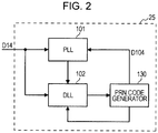
- FIG. 2 is a diagram illustrating the configuration of the synchronization-holding unit 25 in the GPS receiver 10 according to an embodiment of the present invention. Referring now to FIG. 2 , in the following description, the configuration of the synchronization-holding unit 25 in the GPS receiver according to the embodiment of the present invention will be described.
- the synchronization holding performs holding of specific GPS satellite signals from the amplified IF signals D14 from a plurality of GPS signals (hereinafter, referred to as a synchronization-holding channel) .
- the synchronization-holding unit 25 includes a phase-locked loop (PLL) 101 that performs the synchronization-holding on a channel of carriers, a delay-locked loop (DLL) 102 that performs synchronization-holding on a channel of PRN codes, and a PRN code generator 130 that generates PRN codes of specific GPS satellites specified by the CPU 26.
- PLL phase-locked loop
- DLL delay-locked loop
- PRN code generator 130 that generates PRN codes of specific GPS satellites specified by the CPU 26.
- the PLL 101 performs synchronization-holding on a channel of carriers of specific GPS satellite signals from the amplified IF signals D14 from a plurality of GPS satellites, followed by outputting the carrier frequency of the GPS satellite being tracked.
- the carrier frequency thus obtained is supplied to the DLL 102 and also used for positioning calculation via the CPU 26.
- the PLL 101 also performs the extraction of a navigation message and the extracted navigation message is then supplied to the CPU 26.
- the DLL 102 performs synchronization-holding on a channel of PRN signals of specific GPS satellite signals from the amplified IF signals D14 from a plurality of GPS satellites, followed by outputting the phase of the PRN code and the frequency of the GPS satellite being tracked.
- the phase of the PRN code thus obtained in the DLL 102 is supplied to the PLL 101 and also used for positioning calculation via the CPU 26.
- the PRN code frequency thus obtained is supplied to the PRN code generator 130.
- the PRN code generator 130 generates a PRN code corresponding to the PRN code frequency obtained from the DLL 102.
- the type of the PRN code being generated depends on the kind of the GPS satellite to be synchronized and is provided from the CPU 26.
- the configuration of the synchronization-holding unit 25 in the GPS receiver 10 according to the first embodiment of the present invention has been described.
- the configuration of the PLL 101 used in the synchronization-holding channel 100 shown in FIG. 2 will be described after description of an exemplified configuration of the PLL used in the synchronization-holding channel of the typical GPS receiver.
- FIG. 3 is a diagram illustrating the configuration of a PLL 40 used in the synchronization-holding channel of a background GPS receiver which has been used in the art.
- the PLL 40 used in the synchronization-holding channel of the background GPS receiver includes: mixers 41, 42, and 43; LPFs 44 and 45; a phase detector 46; a loop filter 47; and a carrier numeral controlled oscillator (NCO) 48.
- NCO carrier numeral controlled oscillator
- a mixer 41 is provided for removing (or reverse-spreading) a PRN code of the specific GPS satellite signal in an amplified IF signal D14 supplied from the A/D converter 22.
- the amplified IF signal D14 is multiplied by a delay (prompt or punctual) signal D104 of the PRN code output from the PRN code generator 130.
- the signal reverse-spread by the mixer 41 is then supplied to mixers 42 and 43.
- the mixer 42 multiplies the output of the mixer 41 by a cos component output from a carrier NCO 48 to take out an in-phase component (I component) of the specific GPS satellite signal from the output of the mixer 41.
- the I component I P includes the sum and difference between the carrier frequency of the GPS satellite signal being tracked and the frequency of carrier generated from the NCO 48.
- the I component I P obtained in the mixer 42 is then supplied to the LPF 44.
- the output of the mixer 41 is multiplied by a sin component output from the NCO 48.
- the Q component Q P includes the sum and difference between the carrier frequency of the GPS satellite signal being tracked and the frequency of carrier generated from the NCO 48.
- the Q component Q P is supplied to the LPF 45.
- the LPFs 44 and 45 take out the frequency difference among the sum and difference between two frequency components in the outputs of the respective mixers 42 and 43 from the carrier frequency of the GPS satellite signal being tracked and the carrier frequency generated from the NCO 48.
- Each of the LPFs 44 and 45 has a role of removing noises.
- An output of each of the LPFs 44 and 45 is supplied to a phase detector 46.
- a phase detector 46 calculates a phase difference between the carrier of the GPS satellite signal being tracked and the carrier generated from the NCO 48 from the I component I P and the Q component Q P passed through the LPFs 44 and 45, respectively.
- the phase difference obtained by the phase detector 46 is then supplied to a loop filter 47.
- the loop filter 47 is a kind of LPF for realizing a desired loop response while removing an unnecessary noise from the phase difference information generated by phase detector 46.
- the CPU 26 provides the loop filter 47 with proper parameters for the desired loop response.
- An output from the loop filter 47 is supplied to the carrier NCO 48.
- the carrier NCO 48 generates a carrier signal corresponding to frequency according to an input.
- the carrier NCO 48 then outputs a carrier signal D101 used as a standard and a signal D102 with a phase shift of 90 degrees therefrom. From the carrier NCO 48, the output signal D101 is supplied to the mixer 42 and the output signal D102 to the mixer 48.
- the configuration of the PLL 40 used in the synchronization-holding channel of the typical GPS receiver has been described.
- such a typical GPS receiver is provided with one PLL for every synchronization-holding channel. Therefore, both the phase detector 46 and the loop filter 47 are needed for each synchronization-holding channel, and the number of needed phase detectors 46 and loop filters 47 is equal to the number of the synchronization-holding channels.
- an increase in circuit size may occur because of needing the same number of phase detectors and the loop filters as the number of the synchronization-holding channels even if a scale of processing to be carried out during the interval of processing of the PLL is not so large.
- a plurality of synchronization-holding channels share a phase comparator and a loop filter of a PLL and processing is carried out with time sharing, which prevents a desired circuit size from being increased, as now described.
- FIG. 4 is a diagram illustrating the configuration of PLL 111 in a synchronization-holding unit 25 according to one of exemplary embodiments of the present invention. Referring now to FIG. 4 , the configuration of the PLL 111 used in the synchronization-holding unit 25 according to the embodiment of the present invention will be described.
- the PLL 111 includes: a mixer 103 that eliminates a PRN code of a specific GPS satellite signal in an amplified IF signal D14 supplied from the A/D converter 22; a mixer 104 that takes out an I component I P of the carrier of the specific GPS satellite signal; a mixer 105 that takes out a Q component Q P of the carrier of the specific GPS satellite signal; and LPFs 106 and 107 that eliminate an undesired frequency component, such as a noise, caused by band limitation.
- a mixer 103 that eliminates a PRN code of a specific GPS satellite signal in an amplified IF signal D14 supplied from the A/D converter 22
- a mixer 104 that takes out an I component I P of the carrier of the specific GPS satellite signal
- a mixer 105 that takes out a Q component Q P of the carrier of the specific GPS satellite signal
- LPFs 106 and 107 that eliminate an undesired frequency component, such as a noise, caused by band limitation.
- the PLL 111 also includes: a phase detector 113 that detects a phase difference between a carrier in a received GPS satellite signal and a carrier generated from a carrier numerically controlled oscillator (carrier NCO) 110 with reference to the ratio between the I component I P and the Q component Q P ; and a loop filter 114 that smoothes a phase difference output from the phase detector 113.
- a phase detector 113 that detects a phase difference between a carrier in a received GPS satellite signal and a carrier generated from a carrier numerically controlled oscillator (carrier NCO) 110 with reference to the ratio between the I component I P and the Q component Q P ; and a loop filter 114 that smoothes a phase difference output from the phase detector 113.
- carrier NCO carrier numerically controlled oscillator
- the PLL 111 also includes: a carrier NCO 110 that eliminates a carrier of a GPS satellite signal being tracked; a multiplexer (MUX) 116 that selects an I signal connected to the phase detector 113 among I signals from a plurality of channels; and a multiplexer (MUX) 115 that selects a Q signal connected to the phase detector 113 among Q signals from a plurality of channels.
- the PLL 111 includes: a demultiplexer (DEMUX) 117 that selects a carrier NCO 110 connected to a loop filter 114 among the carrier NCOs 110 from a plurality of channels; and a counter 118 that holds which channel signal the multiplexers 115 and 116 and the demultiplexer 117 should select.
- the PLL 111 includes a register 119 that holds an intermediate result, which is generated in the loop filter, for each of plural channels.
- the mixers 103, 104, and 105, the LPFs 106 and 107, and the carrier NCO 110 are provided in an equal number to the number of the synchronization-holding channels, respectively.
- the needed numbers of the phase detector 113, the loop filter 114, the counter 118, the register 119, the multiplexers 115 and 116, and the demultiplexer 117 is less than the number of the synchronization-holding channels.
- a significant improvement in efficiency is realized in the relationship between the number of synchronization-holding channels and the number of the phase difference detectors 112 each including the phase detector 113 and the loop filter 114.
- the number M of the needed phase difference detectors 112 is determined so that it will be less than the number N (N ⁇ 2) of the synchronization-holding channels (N > M). Now, how to determine M when N is given concretely will be described. First, the maximum number L of sharable synchronization-holding channels for one phase difference detector 112 is calculated.
- the number N of the synchronization-holding channels is set to eight (8)
- the number M of the phase difference detectors 112 is set to one (1).
- the number may be larger or smaller as long as it satisfies the aforementioned conditions.
- a mixer 103 is provided for removing (or reverse-spreading) a PRN code of the specific GPS satellite signal in an amplified IF signal D14 supplied from the A/D converter 22.
- the amplified IF signal D 14 is multiplied by a prompt; or punctual signal of the PRN code output from the PRN code generator 130.
- the signal reverse-spread by the mixer 103 is then supplied to mixers 104 and 105.
- the mixer 104 multiplies the output of the mixer 103 by a cos component output from a carrier NCO 110 to take out an I component I P of the specific GPS satellite signal from the output of the mixer 104.
- the I component I P includes the sum and difference between the carrier frequency of the GPS satellite signal being tracked and the frequency of carrier generated from the NCO 110.
- the I component I P taken out by the mixer 104 is then supplied to the LPF 106.
- the mixer 105 multiplies the output of the mixer 103 by a sin component output from a carrier NCO 110 to take out a Q component Q P of the specific GPS satellite signal from the output of the mixer 103.
- the Q ingredient Q P includes the sum and difference between the carrier frequency of the GPS satellite signal being tracked and the frequency of carrier generated from the NCO 110.
- the Q component Q P taken out by the mixer 105 is then supplied to the LPF 107.
- the LPFs 106 and 107 filter out the frequency difference among the sum and difference between two frequency components in the outputs of the respective mixers 104 and 105 from the carrier frequency of the GPS satellite signal being tracked and the carrier frequency generated from the NCO 110.
- Each of the LPFs 106 and 107 has a role of removing noises.
- An output of each of the LPFs 106 and 107 is supplied to a phase detector 113 through multiplexers 115 and 116 described later, respectively.
- a phase detector 113 calculates a phase difference between the carrier of the GPS satellite signal being tracked and the carrier generated from the NCO 48 from the I component I P and the Q component Q P passed through the LPFs 44 and 45, respectively.
- the phase difference information obtained by the phase detector 113 is then supplied to a loop filter 114.
- the loop filter 114 is a kind of LPF for realizing a desired loop response while removing an unnecessary noise from the phase difference information generated by phase detector 113.
- the CPU 26 provides the loop filter 114 with proper parameters for the desired loop response.
- An output from the loop filter 114 is supplied to the carrier NCO 110 through the demultiplexer 117 described later.
- the carrier NCO 110 generates a carrier signal corresponding to frequency according to an input.
- the carrier NCO 110 then outputs a carrier signal D101 used as a standard and a signal D102 with a phase shift of 90 degrees therefrom. From the carrier NCO 110, the output signal D101 is supplied to the mixer 104 and the output signal D102 is supplied to the mixer 105.
- Each of the multiplexers 115 and 116 is provided for selecting an output from a specific synchronization-holding channel among outputs from the LPF 106 and 107 of a plurality of synchronization-holding channels.
- the synchronization-holding channel to be selected is held in the counter 118.
- the demultiplexer 117 is provided for selecting a channel to be connected to the loop filter 114.
- the information of the synchronization-holding channel to be selected is held as a channel number in the counter 118.
- the counter 118 holds the channel number for selecting the signal of the specific synchronization-holding channel among the signals of plural synchronization-holding channels by the multiplexers 115 and 116 and the demultiplexer 117.
- the channel numbers 0 to 7 are held as the number of the synchronization-holding channels is equal to eight. A method of controlling the counter value of the counter 118 will be described later.
- the register 119 is a space for storing the intermediate result generated from the loop filter 114.
- the register 119 may be realized using a flip-flop or RAM but is not limited thereto.
- the intermediate results generated by the loop filter 114 differ for every synchronization-holding channel.
- the register 119 desires to prepare an available storage space corresponding to the number of synchronization-holding channels.
- the counter 118 specifies to which channel region in the register 119 the intermediate result is stored in or to which channel region the intermediate result to be used a next time is taken out from.
- the signal D201 is a signal that represents the end of the calculation of the loop filter 114 and initiates the phase difference detection for the next synchronization-holding channel, which processing is to be carried out by the phase detector 113 and the loop filter 114. Simultaneously, the signal D201 is a signal for updating the counter 118.
- the configuration of the PLL 111 has been described with reference to FIG. 4 .
- the phase difference detectors 112 installed in the respective synchronization-holding channel are started simultaneously by a process start signal generated by the frequency multiplier/demultiplier 12 shown in FIG. 1 .
- one phase difference detector 112 takes charge of the processing of a plurality of synchronization-holding channels with time sharing.
- a signal for starting the processing of the phase difference detector 112 is used in addition to the processing-start signal generated by the frequency multiplier/demultiplier 13.
- a method of generating a processing-start signal of the phase difference detector 112 and a method of controlling the counter 118 in accordance with the present embodiment will be described.
- FIG. 5 is a diagram schematically illustrating a method of generating a processing-start signal of the phase difference detector 112 according to one of the embodiments of the present invention.
- the method of generating a processing-start signal of the phase difference detector 112 according to the embodiment will be described.
- a process start signal generated by the frequency multiplier/demultiplier 13 is utilized as a start signal for processing the channel 0 (zero).
- the process start signals for processing the channels 1 to 7 utilize a process termination signal D201 of the loop filter 114.
- the process termination signal of the last channel (channel 7 in the example shown in FIG. 5 ) is no longer a channel to be processed. Thus, it is not utilized as a process start signal.
- the counter 118 is responsible for determining a synchronization-holding channel to be connected to the multiplexers 115 and 116 and the demultiplexer 117.
- the counter 118 is also responsible for determining a storage space in the register 119 for the intermediate result generated by the loop filter 114 and a storage location in the register 119 for the intermediate result used by the loop filter 114. Basically, the same control as that of the process start signal as described above is performed. In other words, the counter 118 is initialized to zero (0) using a process start signal generated by the frequency multiplier/demultiplexer 13 shown in FIG. 1 and then the counter value of the counter is added with one (1) using a process terminator signal D201 of the loop filter 114. However, the counter 118 does not perform any addition of counter value if the counter already holds the maximum channel number (in this example, 7).
- FIG. 6 is a flow chart showing a method of controlling the counter 118 in the PLL 111 according to one of the embodiments of the present invention.
- the method of controlling the counter 118 in the PLL 111 of the present embodiment will be described with reference to FIG. 6 .
- a series of steps shown in FIG. 6 may be performed by the CPU 26.
- Step S101 it is determined whether the counter 118 has received a process start signal from the frequency multiplier/demultiplier 13 (Step S101).
- the counter value of the counter 118 is initialized to zero (0) (Step S102) and the process is ended.
- Step S103 it is determined whether the counter 118 has received a process termination signal from the loop filter 114 (Step S103).
- Step S104 it is continuously determined whether the counter value of the counter 118 has reached the maximum number of channels to be processed. On the other hand, as a result of the determination in the above step S103, if there is no process termination signal from the loop filter 114, then the process is ended as it is.
- Step S104 if it is determined that the counter value of the counter 118 does not reach the maximum number of channels to be processed, then the counter value of the counter 118 is added with one (1) (Step S105). On the other hand, as a result of the determination in the above step S104, if it is determined that the counter value of the counter 118 has reached the maximum number of channels to be processed, then the process is ended as it is. Furthermore, the process further proceeds to carry out the processing in the above step S101 again, where it is determined whether the process start signal from the frequency multiplier/demultiplier 13 is sent to the counter 118.
- the method of controlling the PLL 111 and the counter 118 of the first embodiment of the present invention has been described in addition to the method of generating the processing-start signal of the phase difference detector 112 of the present embodiment.
- the number of phase difference detectors (including the phase detectors and the loop filters), which have been typically installed in a plurality of synchronization-holding channels existing in the art, can be reduced and the processing of a plurality of synchronization-holding channel channels can be performed using one phase different difference detector with time sharing.
- a reduction in the number of phase difference detectors, which have been installed in each of plural synchronization-holding channels, can be attained.
- a method of synchronization holding or synchronization acquisition of satellites is not assumed to be realized in any specific embodiment. It may be a synchronization acquiring unit and/or a synchronization-holding channel unit to be installed in a GPS receiver.
- various kinds of the processing described in the present embodiment may be sequentially carried out by allowing the CPU 26 to read any computer executable instructions stored in the memory 29 or the like.
Landscapes
- Engineering & Computer Science (AREA)
- Radar, Positioning & Navigation (AREA)
- Remote Sensing (AREA)
- Signal Processing (AREA)
- Computer Networks & Wireless Communication (AREA)
- Physics & Mathematics (AREA)
- General Physics & Mathematics (AREA)
- Position Fixing By Use Of Radio Waves (AREA)
- Stabilization Of Oscillater, Synchronisation, Frequency Synthesizers (AREA)
- Synchronisation In Digital Transmission Systems (AREA)
Claims (12)
- GPS(Global Positioning System, globales Positionsbestimmungssystem)-Vorrichtung (10), umfassend:einen Frequenzwandler (23), der mehrere GPS-Signale (D5) empfängt; undeine Synchronisationshalteschaltung (25), die bestimmte der mehreren GPS-Signale (D5) hält, wobei die Synchronisationshalteschaltung (25) Folgendes umfasst:mehrere PLL-Schaltungen (111), je eine für jeden von mehreren Synchronisationshaltekanälen, wobei jede PLL-Schaltung (111) Mischer (104, 105) aufweist, die ein Signal (D14) vom Frequenzwandler (23) empfangen und eine I-Komponente bzw. eine Q-Komponente aus diesem Signal (D14) entnehmen, im Nachgang von Tiefpassfiltern (106, 107), die eine Differenz in der I-Komponente bzw. in der Q-Komponente und einem Träger-NCO (110), der mit einem Ausgang einer Demultiplexereinheit (117) verbunden ist, herausfiltern ; undeine Multiplexereinheit (115, 116), die die mehreren Signale an den Ausgängen der Tiefpassfilter (106, 107) der mehreren PLL-Schaltungen (111) empfängt und die nach Art des Zeitmultiplexings jedes der mehreren Signale nacheinander auswählt,wenigstens einen Phasendifferenzdetektor (112), der jedes ausgewählte Signal von der Multiplexereinheit (115, 116) empfängt, wobei eine Anzahl (M) der wenigstens einen Phasendifferenzdetektoren (112) kleiner ist als eine Anzahl (N) der mehreren Kanäle,wenigstens eine Demultiplexereinheit (117), die mit einem Ausgang des entsprechenden Phasendifferenzdetektors (112) verbunden ist und die den Träger-NCO (110) einer PLL-Schaltung (111) der mehreren PLL-Schaltungen (111) nach Art des Zeitmultiplexings nacheinander auswählt.
- GPS(Global Positioning System, globales Positionsbestimmungssystem)-Vorrichtung (10) gemäß Anspruch 1, wobei jeder der wenigstens einen Phasendifferenzdetektoren (112) einen Phasendetektor (113) und ein Schleifenfilter (114) aufweist.
- GPS(Global Positioning System, globales Positionsbestimmungssystem)-Vorrichtung (10) gemäß Anspruch 1 oder 2, wobei die Multiplexereinheit (115, 116) einen ersten Multiplexer (116), der ein I-Signal aus dem ausgewählten Signal (D14) auswählt, und einen zweiten Multiplexer (115), der ein Q-Signal aus dem ausgewählten Signal (D14) auswählt, beinhaltet.
- GPS(Global Positioning System, globales Positionsbestimmungssystem)-Vorrichtung (10) gemäß Anspruch 1, 2 oder 3, wobei jeder Signalempfänger (111) ferner umfasst:einen Träger-NCO (Carrier Numerically Controlled Oscillator, trägernumerisch gesteuerter Oszillator) (110), der einen Ausgang von dem wenigstens einen Phasendifferenzdetektor (112) empfängt.
- GPS(Global Positioning System, globales Positionsbestimmungssystem)-Vorrichtung (10) gemäß einem der Ansprüche 1 bis 4, wobei die Synchronisationshalteschaltung (25) ferner umfasst:einen Zähler (118), der eine Kanalnummer hält, welche von der Multiplexereinheit (115, 116) verwendet wird, um das eine der mehreren Signale (D14) auszuwählen, das der gehaltenen Kanalnummer entspricht.
- GPS(Global Positioning System, globales Positionsbestimmungssystem)-Vorrichtung (10) gemäß einem der Ansprüche 1 bis 5,
wobei eine Anzahl der mehreren Kanäle N ist, eine Zeit zur Verarbeitung des ausgewählten Signals für einen jeweiligen Kanal in dem wenigstens einen Phasendifferenzdetektor (112) T1 ist, ein Intervall zwischen der Verarbeitung ausgewählter Signale in dem wenigstens einen Phasendifferenzdetektor T0 ist und
die Anzahl der wenigstens einen Phasendifferenzdetektoren M ist,
wobei


- Signalempfangsverfahren, umfassend:Empfangen, an einem Frequenzwandler (23), mehrerer GPS-Signale (D5);Empfangen, an einem Eingang mehrerer PLL-Schaltungen (111), je einer für jeden von mehreren Synchronisationshaltekanälen einer Synchronisationshalteschaltung (25), eines Signals (D14) vom Frequenzwandler (23);Mischen des empfangenen Signals (D14) an Mischern (104, 105) in der betreffenden PLL-Schaltung (111), um eine I-Komponente bzw. eine Q-Komponente aus dem betreffenden Signal (D14) zu entnehmen;Herausfiltern einer Differenz aus der I-Komponente bzw. aus der Q-Komponente an Tiefpassfiltern (106, 107) in der betreffenden PLL-Schaltung (111);nacheinander Auswählen, an einer Multiplexereinheit (115, 116), die die mehreren Signale von den Ausgängen der Tiefpassfilter (106, 107) in den mehreren PLL-Schaltungen (111) empfängt, jedes einzelnen der mehreren Signale nach Art des Zeitmultiplexings;Ausführen wenigstens einer Phasendifferenzerkennung durch einen Phasendifferenzdetektor (112), an jedem ausgewählten Signal aus der Auswahl an der Multiplexereinheit (115, 116), wobei eine Anzahl (M) der wenigstens einen Phasendifferenzdetektoren (112) kleiner ist als eine Anzahl (N) der mehreren Kanäle;nacheinander Auswählen, an einer Demultiplexereinheit (117), die ein Signal von einem Ausgang des entsprechenden Phasendifferenzdetektors (112) empfängt, des Träger-NCO (110) der betreffenden PLL-Schaltung (111) nach Art des Zeitmultiplexings; undAusgeben eines Trägersignals (D101) am Träger-NCO (110) in der betreffenden PLL-Schaltung (111).
- Signalempfangsverfahren gemäß Anspruch 7, wobei das Ausführen der Phasendifferenzerkennung beinhaltet, eine Phasendetektion auszuführen und eine Schleifenfilterung auszuführen.
- Signalempfangsverfahren gemäß Anspruch 7 oder 8, wobei das Auswählen ein erstes Auswählen eines I-Signals aus dem ausgewählten Signal (D14) und ein zweites Auswählen eines Q-Signals aus dem ausgewählten Signal (D14) beinhaltet.
- Signalempfangsverfahren gemäß Anspruch 7, 8 oder 9, ferner umfassend:trägernumerisch gesteuertes Oszillieren eines Ausgangs der Ausführung der Phasendifferenzerkennung an dem wenigstens einen Phasendifferenzdetektor (112).
- Signalempfangsverfahren gemäß einem der Ansprüche 7 bis 10, ferner umfassend:Halten einer Kanalnummer und Verwenden der gehaltenen Kanalnummer bei der Auswahl, um das eine der mehreren Signale (D14) auszuwählen, das der gehaltenen Kanalnummer entspricht.
- Signalempfangsverfahren gemäß einem der Ansprüche 7 bis 11,
wobei bei der Ausführung der Phasendifferenzerkennung eine Anzahl der mehreren Kanäle N ist, eine Zeit zur Verarbeitung des ausgewählten Signals für einen jeweiligen Kanal in dem wenigstens einen Phasendifferenzdetektor T1 ist, ein Intervall zwischen der Verarbeitung ausgewählter Signale in dem wenigstens einen Phasendifferenzdetektor T0 ist und
die Anzahl der wenigstens einen Phasendifferenzdetektoren M ist,
wobei

 wobei └ ┘ ein Symbol einer Untergrenzenfunktion ist, in der └x┘ die größte Ganzzahl ist, die nicht höher ist als x, undwobei ┌ ┐ ein Symbol einer Obergrenzenfunktion ist, in der ┌X┐ die kleinste Ganzzahl ist, die nicht höher ist als x.
Applications Claiming Priority (1)
| Application Number | Priority Date | Filing Date | Title |
|---|---|---|---|
| JP2009152472A JP5434301B2 (ja) | 2009-06-26 | 2009-06-26 | 信号受信装置、信号受信装置の制御方法及びコンピュータプログラム |
Publications (2)
| Publication Number | Publication Date |
|---|---|
| EP2284573A1 EP2284573A1 (de) | 2011-02-16 |
| EP2284573B1 true EP2284573B1 (de) | 2017-04-05 |
Family
ID=43037610
Family Applications (1)
| Application Number | Title | Priority Date | Filing Date |
|---|---|---|---|
| EP10163997.9A Not-in-force EP2284573B1 (de) | 2009-06-26 | 2010-05-27 | Signalempfänger, Steuerungsverfahren des Signalempfängers, GPS-Vorrichtung mit dem Signalempfänger und Verfahren |
Country Status (4)
| Country | Link |
|---|---|
| US (1) | US8351470B2 (de) |
| EP (1) | EP2284573B1 (de) |
| JP (1) | JP5434301B2 (de) |
| CN (1) | CN101930075B (de) |
Families Citing this family (3)
| Publication number | Priority date | Publication date | Assignee | Title |
|---|---|---|---|---|
| CN109141537A (zh) * | 2018-10-23 | 2019-01-04 | 青岛科技大学 | 一种温度质量双参数传感器硬件电路系统的设计方法 |
| WO2020174460A2 (en) | 2019-02-25 | 2020-09-03 | Luminati Networks Ltd. | System and method for url fetching retry mechanism |
| CN111355487B (zh) * | 2020-03-10 | 2025-01-10 | 新港海岸(北京)科技有限公司 | 一种时钟生成电路和时钟生成器 |
Family Cites Families (9)
| Publication number | Priority date | Publication date | Assignee | Title |
|---|---|---|---|---|
| US5101356A (en) * | 1989-11-21 | 1992-03-31 | Unisys Corporation | Moving vehicle attitude measuring system |
| US6308077B1 (en) * | 1992-10-02 | 2001-10-23 | Motorola, Inc. | Apparatus and method for providing synchronization of base-stations in a communication system |
| US5268695A (en) * | 1992-10-06 | 1993-12-07 | Trimble Navigation Limited | Differential phase measurement through antenna multiplexing |
| JP3626047B2 (ja) * | 1999-10-05 | 2005-03-02 | 株式会社ケンウッド | 同期捕捉回路及び同期捕捉方法 |
| TW567336B (en) * | 2001-05-04 | 2003-12-21 | Asulab Sa | Radio-frequency signal receiver with means for improving the reception dynamic of said signals |
| JP3726897B2 (ja) * | 2002-02-27 | 2005-12-14 | ソニー株式会社 | Gps受信機およびgps衛星信号の受信方法 |
| JP4154609B2 (ja) * | 2004-07-30 | 2008-09-24 | ソニー株式会社 | 衛星信号受信処理装置および衛星信号受信処理方法 |
| JP4844381B2 (ja) * | 2006-12-20 | 2011-12-28 | 株式会社デンソー | Gps受信機およびgps受信機の受信方法 |
| CN101435866B (zh) * | 2008-11-26 | 2012-04-04 | 苏州莱迪斯特电子有限公司 | 一种gps粗/捕获码信号的载波跟踪系统及其方法 |
-
2009
- 2009-06-26 JP JP2009152472A patent/JP5434301B2/ja not_active Expired - Fee Related
-
2010
- 2010-05-27 EP EP10163997.9A patent/EP2284573B1/de not_active Not-in-force
- 2010-06-07 US US12/795,312 patent/US8351470B2/en not_active Expired - Fee Related
- 2010-06-18 CN CN201010208918.7A patent/CN101930075B/zh not_active Expired - Fee Related
Non-Patent Citations (1)
| Title |
|---|
| None * |
Also Published As
| Publication number | Publication date |
|---|---|
| JP5434301B2 (ja) | 2014-03-05 |
| JP2011007679A (ja) | 2011-01-13 |
| CN101930075A (zh) | 2010-12-29 |
| US8351470B2 (en) | 2013-01-08 |
| EP2284573A1 (de) | 2011-02-16 |
| US20100329237A1 (en) | 2010-12-30 |
| CN101930075B (zh) | 2016-01-20 |
Similar Documents
| Publication | Publication Date | Title |
|---|---|---|
| JP4120237B2 (ja) | 復調装置及び受信装置 | |
| US4894842A (en) | Precorrelation digital spread spectrum receiver | |
| US8369386B2 (en) | Receiver, signal processing method and program | |
| EP2237422B1 (de) | Phasenregelschleife mit variabeler ordnung und rekonfigurierbaren Schleifenfilter und ihre Anwendung in einem GPS-Empfänger | |
| JP4154609B2 (ja) | 衛星信号受信処理装置および衛星信号受信処理方法 | |
| US6907346B2 (en) | GPS receiver apparatus and receiving method | |
| EP2006706B1 (de) | Kohärentes Integrationsverbesserungsverfahren, Positionierungsverfahren, Speichermedium, kohärente Integrationsverbesserungsschaltung, Positionierungsschaltung und elektronisches Instrument | |
| JP2003028945A (ja) | 信号の受信ダイナミックを改善するための手段を有する無線周波数信号受信機 | |
| US8351470B2 (en) | Signal receiver, control method of signal receiver, and GPS device utilizing the signal receiver and method | |
| US7053825B2 (en) | Communication device | |
| US8953721B2 (en) | Cross correlation determination method and cross correlation determination device | |
| JP4306693B2 (ja) | 相関検出装置、相関検出方法並びに受信装置 | |
| CN102650695B (zh) | 卫星电波接收装置 | |
| JP2003255036A (ja) | 受信装置 | |
| TWI510801B (zh) | 用以處理信號之裝置與方法、包含該裝置之積體電路或晶片組與定位裝置、電腦程式產品及承載媒體 | |
| US7499485B2 (en) | Method and apparatus for detecting GPS data-bit boundaries and detecting GPS satellite-signal reception | |
| JP3956722B2 (ja) | マッチドフィルタ装置及び相関検出方法並びに受信装置 | |
| JP3864807B2 (ja) | 相関検出装置及び相関検出方法並びに受信装置 | |
| CN104049264A (zh) | 接收电路、接收装置以及接收方法 | |
| JP2003258681A (ja) | マッチドフィルタ装置及び相関検出方法並びに受信装置 | |
| WO2015129481A1 (ja) | 受信装置および受信方法 | |
| JP2006170701A (ja) | 時刻設定回路及びこれを用いた携帯無線通信装置 |
Legal Events
| Date | Code | Title | Description |
|---|---|---|---|
| PUAI | Public reference made under article 153(3) epc to a published international application that has entered the european phase |
Free format text: ORIGINAL CODE: 0009012 |
|
| 17P | Request for examination filed |
Effective date: 20100527 |
|
| AK | Designated contracting states |
Kind code of ref document: A1 Designated state(s): AL AT BE BG CH CY CZ DE DK EE ES FI FR GB GR HR HU IE IS IT LI LT LU LV MC MK MT NL NO PL PT RO SE SI SK SM TR |
|
| AX | Request for extension of the european patent |
Extension state: BA ME RS |
|
| GRAP | Despatch of communication of intention to grant a patent |
Free format text: ORIGINAL CODE: EPIDOSNIGR1 |
|
| INTG | Intention to grant announced |
Effective date: 20161005 |
|
| GRAS | Grant fee paid |
Free format text: ORIGINAL CODE: EPIDOSNIGR3 |
|
| GRAJ | Information related to disapproval of communication of intention to grant by the applicant or resumption of examination proceedings by the epo deleted |
Free format text: ORIGINAL CODE: EPIDOSDIGR1 |
|
| GRAL | Information related to payment of fee for publishing/printing deleted |
Free format text: ORIGINAL CODE: EPIDOSDIGR3 |
|
| GRAR | Information related to intention to grant a patent recorded |
Free format text: ORIGINAL CODE: EPIDOSNIGR71 |
|
| GRAA | (expected) grant |
Free format text: ORIGINAL CODE: 0009210 |
|
| INTC | Intention to grant announced (deleted) | ||
| AK | Designated contracting states |
Kind code of ref document: B1 Designated state(s): AL AT BE BG CH CY CZ DE DK EE ES FI FR GB GR HR HU IE IS IT LI LT LU LV MC MK MT NL NO PL PT RO SE SI SK SM TR |
|
| INTG | Intention to grant announced |
Effective date: 20170228 |
|
| REG | Reference to a national code |
Ref country code: GB Ref legal event code: FG4D |
|
| REG | Reference to a national code |
Ref country code: CH Ref legal event code: EP |
|
| REG | Reference to a national code |
Ref country code: AT Ref legal event code: REF Ref document number: 882318 Country of ref document: AT Kind code of ref document: T Effective date: 20170415 |
|
| REG | Reference to a national code |
Ref country code: IE Ref legal event code: FG4D |
|
| REG | Reference to a national code |
Ref country code: DE Ref legal event code: R096 Ref document number: 602010041240 Country of ref document: DE |
|
| REG | Reference to a national code |
Ref country code: NL Ref legal event code: MP Effective date: 20170405 |
|
| REG | Reference to a national code |
Ref country code: LT Ref legal event code: MG4D |
|
| REG | Reference to a national code |
Ref country code: AT Ref legal event code: MK05 Ref document number: 882318 Country of ref document: AT Kind code of ref document: T Effective date: 20170405 |
|
| PG25 | Lapsed in a contracting state [announced via postgrant information from national office to epo] |
Ref country code: NL Free format text: LAPSE BECAUSE OF FAILURE TO SUBMIT A TRANSLATION OF THE DESCRIPTION OR TO PAY THE FEE WITHIN THE PRESCRIBED TIME-LIMIT Effective date: 20170405 |
|
| PG25 | Lapsed in a contracting state [announced via postgrant information from national office to epo] |
Ref country code: HR Free format text: LAPSE BECAUSE OF FAILURE TO SUBMIT A TRANSLATION OF THE DESCRIPTION OR TO PAY THE FEE WITHIN THE PRESCRIBED TIME-LIMIT Effective date: 20170405 Ref country code: FI Free format text: LAPSE BECAUSE OF FAILURE TO SUBMIT A TRANSLATION OF THE DESCRIPTION OR TO PAY THE FEE WITHIN THE PRESCRIBED TIME-LIMIT Effective date: 20170405 Ref country code: GR Free format text: LAPSE BECAUSE OF FAILURE TO SUBMIT A TRANSLATION OF THE DESCRIPTION OR TO PAY THE FEE WITHIN THE PRESCRIBED TIME-LIMIT Effective date: 20170706 Ref country code: ES Free format text: LAPSE BECAUSE OF FAILURE TO SUBMIT A TRANSLATION OF THE DESCRIPTION OR TO PAY THE FEE WITHIN THE PRESCRIBED TIME-LIMIT Effective date: 20170405 Ref country code: LT Free format text: LAPSE BECAUSE OF FAILURE TO SUBMIT A TRANSLATION OF THE DESCRIPTION OR TO PAY THE FEE WITHIN THE PRESCRIBED TIME-LIMIT Effective date: 20170405 Ref country code: NO Free format text: LAPSE BECAUSE OF FAILURE TO SUBMIT A TRANSLATION OF THE DESCRIPTION OR TO PAY THE FEE WITHIN THE PRESCRIBED TIME-LIMIT Effective date: 20170705 Ref country code: AT Free format text: LAPSE BECAUSE OF FAILURE TO SUBMIT A TRANSLATION OF THE DESCRIPTION OR TO PAY THE FEE WITHIN THE PRESCRIBED TIME-LIMIT Effective date: 20170405 |
|
| PG25 | Lapsed in a contracting state [announced via postgrant information from national office to epo] |
Ref country code: BG Free format text: LAPSE BECAUSE OF FAILURE TO SUBMIT A TRANSLATION OF THE DESCRIPTION OR TO PAY THE FEE WITHIN THE PRESCRIBED TIME-LIMIT Effective date: 20170705 Ref country code: IS Free format text: LAPSE BECAUSE OF FAILURE TO SUBMIT A TRANSLATION OF THE DESCRIPTION OR TO PAY THE FEE WITHIN THE PRESCRIBED TIME-LIMIT Effective date: 20170805 Ref country code: SE Free format text: LAPSE BECAUSE OF FAILURE TO SUBMIT A TRANSLATION OF THE DESCRIPTION OR TO PAY THE FEE WITHIN THE PRESCRIBED TIME-LIMIT Effective date: 20170405 Ref country code: PL Free format text: LAPSE BECAUSE OF FAILURE TO SUBMIT A TRANSLATION OF THE DESCRIPTION OR TO PAY THE FEE WITHIN THE PRESCRIBED TIME-LIMIT Effective date: 20170405 Ref country code: LV Free format text: LAPSE BECAUSE OF FAILURE TO SUBMIT A TRANSLATION OF THE DESCRIPTION OR TO PAY THE FEE WITHIN THE PRESCRIBED TIME-LIMIT Effective date: 20170405 |
|
| REG | Reference to a national code |
Ref country code: CH Ref legal event code: PL |
|
| REG | Reference to a national code |
Ref country code: DE Ref legal event code: R097 Ref document number: 602010041240 Country of ref document: DE |
|
| PG25 | Lapsed in a contracting state [announced via postgrant information from national office to epo] |
Ref country code: DK Free format text: LAPSE BECAUSE OF FAILURE TO SUBMIT A TRANSLATION OF THE DESCRIPTION OR TO PAY THE FEE WITHIN THE PRESCRIBED TIME-LIMIT Effective date: 20170405 Ref country code: SK Free format text: LAPSE BECAUSE OF FAILURE TO SUBMIT A TRANSLATION OF THE DESCRIPTION OR TO PAY THE FEE WITHIN THE PRESCRIBED TIME-LIMIT Effective date: 20170405 Ref country code: RO Free format text: LAPSE BECAUSE OF FAILURE TO SUBMIT A TRANSLATION OF THE DESCRIPTION OR TO PAY THE FEE WITHIN THE PRESCRIBED TIME-LIMIT Effective date: 20170405 Ref country code: EE Free format text: LAPSE BECAUSE OF FAILURE TO SUBMIT A TRANSLATION OF THE DESCRIPTION OR TO PAY THE FEE WITHIN THE PRESCRIBED TIME-LIMIT Effective date: 20170405 Ref country code: CZ Free format text: LAPSE BECAUSE OF FAILURE TO SUBMIT A TRANSLATION OF THE DESCRIPTION OR TO PAY THE FEE WITHIN THE PRESCRIBED TIME-LIMIT Effective date: 20170405 Ref country code: MC Free format text: LAPSE BECAUSE OF FAILURE TO SUBMIT A TRANSLATION OF THE DESCRIPTION OR TO PAY THE FEE WITHIN THE PRESCRIBED TIME-LIMIT Effective date: 20170405 |
|
| PLBE | No opposition filed within time limit |
Free format text: ORIGINAL CODE: 0009261 |
|
| STAA | Information on the status of an ep patent application or granted ep patent |
Free format text: STATUS: NO OPPOSITION FILED WITHIN TIME LIMIT |
|
| REG | Reference to a national code |
Ref country code: IE Ref legal event code: MM4A |
|
| PG25 | Lapsed in a contracting state [announced via postgrant information from national office to epo] |
Ref country code: LI Free format text: LAPSE BECAUSE OF NON-PAYMENT OF DUE FEES Effective date: 20170531 Ref country code: CH Free format text: LAPSE BECAUSE OF NON-PAYMENT OF DUE FEES Effective date: 20170531 Ref country code: IT Free format text: LAPSE BECAUSE OF FAILURE TO SUBMIT A TRANSLATION OF THE DESCRIPTION OR TO PAY THE FEE WITHIN THE PRESCRIBED TIME-LIMIT Effective date: 20170405 Ref country code: SM Free format text: LAPSE BECAUSE OF FAILURE TO SUBMIT A TRANSLATION OF THE DESCRIPTION OR TO PAY THE FEE WITHIN THE PRESCRIBED TIME-LIMIT Effective date: 20170405 |
|
| REG | Reference to a national code |
Ref country code: FR Ref legal event code: ST Effective date: 20180131 |
|
| 26N | No opposition filed |
Effective date: 20180108 |
|
| PG25 | Lapsed in a contracting state [announced via postgrant information from national office to epo] |
Ref country code: LU Free format text: LAPSE BECAUSE OF NON-PAYMENT OF DUE FEES Effective date: 20170527 |
|
| REG | Reference to a national code |
Ref country code: BE Ref legal event code: MM Effective date: 20170531 |
|
| PG25 | Lapsed in a contracting state [announced via postgrant information from national office to epo] |
Ref country code: IE Free format text: LAPSE BECAUSE OF NON-PAYMENT OF DUE FEES Effective date: 20170527 |
|
| PG25 | Lapsed in a contracting state [announced via postgrant information from national office to epo] |
Ref country code: FR Free format text: LAPSE BECAUSE OF NON-PAYMENT OF DUE FEES Effective date: 20170606 Ref country code: SI Free format text: LAPSE BECAUSE OF FAILURE TO SUBMIT A TRANSLATION OF THE DESCRIPTION OR TO PAY THE FEE WITHIN THE PRESCRIBED TIME-LIMIT Effective date: 20170405 |
|
| PG25 | Lapsed in a contracting state [announced via postgrant information from national office to epo] |
Ref country code: BE Free format text: LAPSE BECAUSE OF NON-PAYMENT OF DUE FEES Effective date: 20170531 |
|
| PG25 | Lapsed in a contracting state [announced via postgrant information from national office to epo] |
Ref country code: MT Free format text: LAPSE BECAUSE OF NON-PAYMENT OF DUE FEES Effective date: 20170527 |
|
| PG25 | Lapsed in a contracting state [announced via postgrant information from national office to epo] |
Ref country code: HU Free format text: LAPSE BECAUSE OF FAILURE TO SUBMIT A TRANSLATION OF THE DESCRIPTION OR TO PAY THE FEE WITHIN THE PRESCRIBED TIME-LIMIT; INVALID AB INITIO Effective date: 20100527 |
|
| PG25 | Lapsed in a contracting state [announced via postgrant information from national office to epo] |
Ref country code: CY Free format text: LAPSE BECAUSE OF NON-PAYMENT OF DUE FEES Effective date: 20170405 |
|
| PG25 | Lapsed in a contracting state [announced via postgrant information from national office to epo] |
Ref country code: MK Free format text: LAPSE BECAUSE OF FAILURE TO SUBMIT A TRANSLATION OF THE DESCRIPTION OR TO PAY THE FEE WITHIN THE PRESCRIBED TIME-LIMIT Effective date: 20170405 |
|
| PG25 | Lapsed in a contracting state [announced via postgrant information from national office to epo] |
Ref country code: TR Free format text: LAPSE BECAUSE OF FAILURE TO SUBMIT A TRANSLATION OF THE DESCRIPTION OR TO PAY THE FEE WITHIN THE PRESCRIBED TIME-LIMIT Effective date: 20170405 |
|
| PG25 | Lapsed in a contracting state [announced via postgrant information from national office to epo] |
Ref country code: PT Free format text: LAPSE BECAUSE OF FAILURE TO SUBMIT A TRANSLATION OF THE DESCRIPTION OR TO PAY THE FEE WITHIN THE PRESCRIBED TIME-LIMIT Effective date: 20170405 |
|
| PG25 | Lapsed in a contracting state [announced via postgrant information from national office to epo] |
Ref country code: AL Free format text: LAPSE BECAUSE OF FAILURE TO SUBMIT A TRANSLATION OF THE DESCRIPTION OR TO PAY THE FEE WITHIN THE PRESCRIBED TIME-LIMIT Effective date: 20170405 |
|
| REG | Reference to a national code |
Ref country code: GB Ref legal event code: 746 Effective date: 20211108 |
|
| PGFP | Annual fee paid to national office [announced via postgrant information from national office to epo] |
Ref country code: GB Payment date: 20220426 Year of fee payment: 13 Ref country code: DE Payment date: 20220420 Year of fee payment: 13 |
|
| P01 | Opt-out of the competence of the unified patent court (upc) registered |
Effective date: 20230527 |
|
| REG | Reference to a national code |
Ref country code: DE Ref legal event code: R119 Ref document number: 602010041240 Country of ref document: DE |
|
| GBPC | Gb: european patent ceased through non-payment of renewal fee |
Effective date: 20230527 |
|
| PG25 | Lapsed in a contracting state [announced via postgrant information from national office to epo] |
Ref country code: DE Free format text: LAPSE BECAUSE OF NON-PAYMENT OF DUE FEES Effective date: 20231201 Ref country code: GB Free format text: LAPSE BECAUSE OF NON-PAYMENT OF DUE FEES Effective date: 20230527 |