EP2236715B1 - Feststellvorrichtung und Fenster oder Tür mit einer Feststellvorrichtung - Google Patents
Feststellvorrichtung und Fenster oder Tür mit einer Feststellvorrichtung Download PDFInfo
- Publication number
- EP2236715B1 EP2236715B1 EP10000258.3A EP10000258A EP2236715B1 EP 2236715 B1 EP2236715 B1 EP 2236715B1 EP 10000258 A EP10000258 A EP 10000258A EP 2236715 B1 EP2236715 B1 EP 2236715B1
- Authority
- EP
- European Patent Office
- Prior art keywords
- support element
- leaf
- accordance
- frame
- fixing
- Prior art date
- Legal status (The legal status is an assumption and is not a legal conclusion. Google has not performed a legal analysis and makes no representation as to the accuracy of the status listed.)
- Active
Links
Images



Classifications
-
- E—FIXED CONSTRUCTIONS
- E05—LOCKS; KEYS; WINDOW OR DOOR FITTINGS; SAFES
- E05C—BOLTS OR FASTENING DEVICES FOR WINGS, SPECIALLY FOR DOORS OR WINDOWS
- E05C17/00—Devices for holding wings open; Devices for limiting opening of wings or for holding wings open by a movable member extending between frame and wing; Braking devices, stops or buffers, combined therewith
- E05C17/02—Devices for holding wings open; Devices for limiting opening of wings or for holding wings open by a movable member extending between frame and wing; Braking devices, stops or buffers, combined therewith by mechanical means
- E05C17/04—Devices for holding wings open; Devices for limiting opening of wings or for holding wings open by a movable member extending between frame and wing; Braking devices, stops or buffers, combined therewith by mechanical means with a movable bar or equivalent member extending between frame and wing
- E05C17/12—Devices for holding wings open; Devices for limiting opening of wings or for holding wings open by a movable member extending between frame and wing; Braking devices, stops or buffers, combined therewith by mechanical means with a movable bar or equivalent member extending between frame and wing consisting of a single rod
- E05C17/24—Devices for holding wings open; Devices for limiting opening of wings or for holding wings open by a movable member extending between frame and wing; Braking devices, stops or buffers, combined therewith by mechanical means with a movable bar or equivalent member extending between frame and wing consisting of a single rod pivoted at one end, and with the other end running along a guide member
- E05C17/28—Devices for holding wings open; Devices for limiting opening of wings or for holding wings open by a movable member extending between frame and wing; Braking devices, stops or buffers, combined therewith by mechanical means with a movable bar or equivalent member extending between frame and wing consisting of a single rod pivoted at one end, and with the other end running along a guide member with braking, clamping or securing means at the connection to the guide member
-
- E—FIXED CONSTRUCTIONS
- E05—LOCKS; KEYS; WINDOW OR DOOR FITTINGS; SAFES
- E05C—BOLTS OR FASTENING DEVICES FOR WINGS, SPECIALLY FOR DOORS OR WINDOWS
- E05C17/00—Devices for holding wings open; Devices for limiting opening of wings or for holding wings open by a movable member extending between frame and wing; Braking devices, stops or buffers, combined therewith
- E05C17/02—Devices for holding wings open; Devices for limiting opening of wings or for holding wings open by a movable member extending between frame and wing; Braking devices, stops or buffers, combined therewith by mechanical means
- E05C17/025—Means acting between hinged edge and frame
Definitions
- the present invention relates to a locking device for a window frame and a rotatable or moskippbar mounted wing comprehensive windows, doors or the like with a locking arm, at one end for pivotally mounting the locking arm formed on the frame first bearing element and at the other end to the pivotable bearings of the locking arm on the wing trained second bearing element is provided. Furthermore, the invention is directed to a window or a door with a frame and a rotatably mounted thereon wings and with a mounted between the wing and the frame locking device.
- Locking devices of the type mentioned initially include a horizontally arranged locking arm, which is pivotally mounted on the upper or lower horizontally disposed cross member of the wing and the corresponding upper or lower horizontally extending cross member of the frame. With such locking devices open wings can be kept in any position to prevent an automatic closing or an undesirable further opening of the wing.
- locking arm of such locking devices protrudes with the wing open in the opening portion of the wing, which may be annoying depending on the application.
- locking devices can not be used in French doors with thresholds or continuous floor.
- the WO 96/33330 A1 discloses a locking device for a window sash with a hinge side arranged pivot arm, one end of which can be brought by means of a rotary knob selectively in and out of engagement with a bearing element of the window frame.
- the object is achieved by a locking device having the features of claim 1 and a window or a door having the features of claim 13.
- the first bearing element are designed for attachment to the strip side rail of the frame and the second bearing element for attachment to the belt side rail of the wing.
- An inventively designed window or a door designed according to the invention comprises a locking device designed according to the invention, the first bearing element being arranged on the strip side rail of the window frame and the second bearing element being arranged on the strip side rail of the leaf.
- An inventively designed locking device is designed so that it can not be attached to the horizontal bars but on the band-side vertical bars of the wing and the frame. In this way, the locking device can be used even with very narrow windows or doors. Furthermore, it is avoided that with the wing open the locking arm is arranged disturbing in the opening area between the wing and the frame. Thus, the use in windows or doors, which are equipped with a threshold or continuous floor, possible.
- the first and the second bearing element each have three rotational degrees of freedom.
- the locking arm according to the invention thus both relative to the frame and against the wing about all three mutually perpendicular, the space spanning possible axes of rotation is rotatable. This ensures that the locking arm can perform the required during installation in the hinge side hinge air complex pivotal movement relative to the frame and against the wing.
- the first and / or the second bearing element comprise a ball joint with a ball head and a ball socket, in which the ball head is rotatably mounted.
- the ball socket can cover the ball head over a large area or only over certain portions of the ball head.
- At least one of the ball heads is held in the ball socket by a particular automatically releasable latching connection. This ensures that when a force is applied to the wing located in its maximum opening position the locking connection is automatically released when a predetermined force is exceeded, so that no loads acting on supporting components of the window or the door and, for example, a fracture of a bearing is prevented.
- the first and / or the second bearing element comprises an automatically releasable fastening device for attachment to the frame or on the wing.
- the bearing element can thus be fastened automatically releasably on the frame or on the wing in order to achieve the required safety-relevant self-solution.
- the fastening device may be formed as a latching connection.
- the first and / or the second bearing element relative to the frame or against the wing are designed to be displaceable.
- the second bearing element may be designed for displaceable mounting in a fitting receiving groove of the wing.
- the second bearing element comprises a sliding element designed for displaceable mounting in the fitting receiving groove of the wing.
- At least one of the ends of the locking arm can be displaced so that opening and closing of the window or the door is possible.
- the displaceability of the bearing elements of the locking arm has an adjustable length and is in particular formed telescopically.
- At least one brake unit is provided, via which the ease of movement of Displacement of the first and / or the second bearing element is adjustable.
- the brake unit may comprise adjusting means, in particular in the form of at least one adjusting screw.
- adjusting means in particular in the form of at least one adjusting screw.
- the brake unit thus the braking effect of the locking device, for example, depending on the application or size of the wing individually adjustable.
- such a brake unit can also be provided in the design of the length-adjustable locking arm.
- At least one further locking arm is provided for connecting the belt-side rail of the window frame and the belt-side rail of the wing.
- a common bearing element for the storage of several, in particular of two locking arms can be formed.
- the two locking arms can also be mounted on particular spaced different bearing elements.
- This embodiment can be used in particular for larger wings with high weight in order to achieve a sufficient braking effect on the two or more locking arms.
- the locking arm has a circular cross-section, and is designed in particular as a locking rod.
- the forces occurring in particular the pressure forces occurring during the closing of the wing, can be safely absorbed, since due to the circular cross-section, a higher rigidity than for example in a flat-shaped locking arm is achieved.
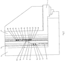
- Fig. 1 shows a wing 1 of a window which is rotatably supported by a corner bearing 2 on a frame 3. Between a vertical strip side mounted spar 4 of the wing 1 and a vertical strip side rail 5 of the frame 3, a locking device 6 is arranged, through which an opening limitation of the wing 1 and a determination between the closed position of the wing 1 and its maximum open position can be reached.
- the locking device 6 comprises a rod-shaped locking arm 7 with a circular cross-section, at the ends of each ball heads 8, 9 are formed, as in particular Fig. 6 can be seen more clearly.
- the ball head 8 is in a ball socket 10 (see FIGS. 9 and 10 ) of a first bearing element 11, which forms a ball joint 12 for the locking arm 7 together with the ball head 8.
- the first bearing element 11 is screwed by two screws 13 to the strip side rail 5 of the frame 3 and thereby fixed immovably to this.
- the ball head 9 is in a ball socket 14 (see Fig. 7, 8 ) of a second bearing element 15, which thus forms, together with the ball head 9, a further ball joint 16 for the locking arm 7.
- the second bearing element 15 comprises a sliding member 17 which is slidably mounted in a fitting receiving groove 18 of the wing 1.
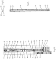
- a guide rail 19 is arranged in the fitting receiving groove 18, which in the 4 and 5 is shown in more detail.
- a bore 20 is formed, into which an adjusting means, in particular in the form of an adjusting screw, preferably an Allen screw, can be screwed.
- This braking means can for example arise from the fact that below the sliding member 17 in the region of the bore 20, a spreader is provided by the side by screwing the adjusting screw, in particular radially outward is urged and thereby jammed with the guide rail 19.
- the guided through the bore 20 adjusting screw on further screwing on the bottom 21 (see 4 and 5 ) of the guide rail 19 comes to rest and thereby generates a braking effect.
- the stiffness of the displaceability of the sliding element 17 and thus the braking effect of the locking device 6 can be adjusted individually.
- a limiting element 22 in the form of a sliding block 22 ' is arranged, which is screwed by screws 23 to the wing 1.
- a further sliding block 24 is fastened with screws 25 on the wing 1, but this sliding block 24 is arranged so that when the window is completely closed, the upper edge of the sliding element 17 is spaced from the lower edge of the sliding block 24 ,
- the required pivotal and rotational movement of the Feststellarms 7 between the open position of the wing 1 and its closed position is made possible by the three rotational degrees of freedom having ball joints 12 and 16 and the displaceability of the second bearing element 15.
- the entire fitting arrangement including the Feststellarms 7 is disposed within the band-side located seaming air of the window with the wing closed 1.
- the guide rail 19 has at its base 21 holes 27 through which it can be fastened together with the limiting element 22 and the sliding block 24 on the wing 1.
- the limiting element 22 and the sliding block 24 may comprise lateral guide grooves, via which they are guided on corresponding guide lugs 28 in the upper region of the guide rail 19 (see Fig. 5 ) are insertable.
- the locking arm 7 comprises a cylindrically shaped central region 28, at the ends in each case a frusto-conical portion 29 connects, at the ends in turn each of the ball heads 8, 9 are arranged.
- the part 26 of the second bearing element 15 comprises a lateral inclined surface 30, in which the ball socket 14 is formed.
- a pin-shaped locking element 32 is formed with two locking lugs 33 which forms a latching connection 34 together with a corresponding bore in the sliding member 17.
- the above-mentioned rotatability of the part 26 around the axis of rotation 35 is made possible by the circular outer cross section of the peg-shaped latching element 32.
- Fig. 9 shows a part 36 of the first bearing element 11, which is designed as a first closing part half 37.
- the closing half 37 has two opposite inclined end faces 38, in each of which two halves of the ball cups 10 are formed.
- the in Fig. 10 illustrated closure member 39 which forms the first bearing element 11.
- An exact centering of the two closing part halves 37 takes place through annular projections 40 and corresponding circular recesses 41 which engage in the assembly of the closing part halves 37 into one another.
- the lugs 40 and the recesses 41 are each provided with a bore 42 through which the screws 13 for securing the first bearing element 11 to the frame 3 can be passed.
- the second ball socket 10 in the second embodiment according to the Fig. 11 to 15 necessary.
- elements already described for the first embodiment are given the same reference numerals as in FIGS Fig. 1 to 10 designated.
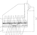
- the locking device 6 'shown in the second embodiment differs from the locking device according to the Fig. 1 to 5 only in that two locking arms 7 are provided, the ends of which are pivotable on two symmetrically formed second bearing elements 15 are stored.
- the two other ends of the two locking arms 7 are each pivotally mounted on the ball heads 8 in the two spherical shells 10 of the common first bearing element 11.
- a longer guide rail 19 ' is provided to allow each of the leadership of the two sliding elements 17 of the two second bearing elements 15.
- the locking arms 7 can also be mounted on spaced-apart bearing elements 11, one of which can be arranged, for example, in the region of the lower corner bearing and the other in the region of an upper corner bearing or a shear bearing. An arrangement in another area between the upper and the lower end of the frame is possible.
- the latching connection 34 it is ensured that act on a force acting on the already fully open wing 1, for example by a person running against the wing 1, no increased forces on supporting components, such as the corner bearing 2, but an automatic solution of the locking connection 34th According to the first embodiment and the two latching connections 34 according to the second embodiment takes place and thus a fracture of the corner bearing 2 and associated with a crash of the wing 1 can be reliably prevented.
- the locking device in the band area in particular a completely hidden training is possible.
- the locking device may also be partially concealed or arranged visibly.
Landscapes
- Engineering & Computer Science (AREA)
- Mechanical Engineering (AREA)
- Wing Frames And Configurations (AREA)
- Closing And Opening Devices For Wings, And Checks For Wings (AREA)
Priority Applications (1)
| Application Number | Priority Date | Filing Date | Title |
|---|---|---|---|
| PL10000258T PL2236715T3 (pl) | 2009-03-16 | 2010-01-13 | Urządzenie ustalające i okno lub drzwi z urządzeniem ustalającym |
Applications Claiming Priority (1)
| Application Number | Priority Date | Filing Date | Title |
|---|---|---|---|
| DE202009003728U DE202009003728U1 (de) | 2009-03-16 | 2009-03-16 | Feststellvorrichtung und Fenster oder Tür mit einer Feststellvorrichtung |
Publications (3)
| Publication Number | Publication Date |
|---|---|
| EP2236715A2 EP2236715A2 (de) | 2010-10-06 |
| EP2236715A3 EP2236715A3 (de) | 2014-12-10 |
| EP2236715B1 true EP2236715B1 (de) | 2017-03-15 |
Family
ID=42198868
Family Applications (1)
| Application Number | Title | Priority Date | Filing Date |
|---|---|---|---|
| EP10000258.3A Active EP2236715B1 (de) | 2009-03-16 | 2010-01-13 | Feststellvorrichtung und Fenster oder Tür mit einer Feststellvorrichtung |
Country Status (3)
| Country | Link |
|---|---|
| EP (1) | EP2236715B1 (pl) |
| DE (1) | DE202009003728U1 (pl) |
| PL (1) | PL2236715T3 (pl) |
Family Cites Families (5)
| Publication number | Priority date | Publication date | Assignee | Title |
|---|---|---|---|---|
| DE2254770A1 (de) * | 1972-11-09 | 1974-05-16 | Daimler Benz Ag | Tuerhalter fuer fahrzeuge, insbesondere fuer kraftfahrzeuge |
| GB2258493A (en) * | 1991-08-06 | 1993-02-10 | Hago Prod Ltd | Window lock |
| SE9501416L (sv) * | 1995-04-19 | 1996-03-25 | Evald Johansson | Anordning vid fönster |
| GB2357316B (en) * | 1999-12-16 | 2002-02-27 | Giovanni Maria Laporta | Door or window stop |
| EP1905929A1 (de) * | 2006-09-29 | 2008-04-02 | Siefried Willa | Vorrichtung zur Arretierung eines Fensterladens |
-
2009
- 2009-03-16 DE DE202009003728U patent/DE202009003728U1/de not_active Expired - Lifetime
-
2010
- 2010-01-13 PL PL10000258T patent/PL2236715T3/pl unknown
- 2010-01-13 EP EP10000258.3A patent/EP2236715B1/de active Active
Non-Patent Citations (1)
| Title |
|---|
| None * |
Also Published As
| Publication number | Publication date |
|---|---|
| PL2236715T3 (pl) | 2017-08-31 |
| DE202009003728U1 (de) | 2010-08-12 |
| EP2236715A3 (de) | 2014-12-10 |
| EP2236715A2 (de) | 2010-10-06 |
Similar Documents
| Publication | Publication Date | Title |
|---|---|---|
| EP2107199B1 (de) | Beschlag für einen zumindest kippbaren und/oder parallelabstellbaren Flügel eines Fensters, einer Tür oder dergleichen | |
| EP2108073B1 (de) | Verdeckt liegender beschlag für ein fenster oder eine tür | |
| EP2130997B1 (de) | Tür mit einem Türband | |
| EP2206861B1 (de) | Türbandanordnung | |
| EP1830024A2 (de) | Beschlag für Fenster oder Türen | |
| EP3168398A1 (de) | Verstecktes scharnier für türen, fenster oder ähnliche bauteile | |
| EP1017920B1 (de) | Beschlag zur drehlagerung eines fenster- oder türflügels | |
| EP3045634B1 (de) | Ausstellvorrichtung für ein fenster oder eine tür mit einer energiespeichereinrichtung | |
| EP2402532B1 (de) | Türband, insbesondere für Hohlprofilzargen | |
| DE102011085177A1 (de) | Antriebssystem für ein KFZ-Dachsystem | |
| DE10250054B4 (de) | Schiebewand | |
| DE29710854U1 (de) | Schrank | |
| EP2236715B1 (de) | Feststellvorrichtung und Fenster oder Tür mit einer Feststellvorrichtung | |
| EP2369111B1 (de) | Zur verdeckten Anordnung vorgesehenes Ecklager | |
| EP4085177B1 (de) | Lagersystem für eine tür | |
| EP0874123B1 (de) | Beschlag zur Lagerung des Drehflügels eines Fensters oder einer Tür | |
| DE4221083C2 (de) | Karusselltür | |
| CH649341A5 (en) | Corner joint on a turn-and-tilt window or on a turn-and-tilt door | |
| EP2740872B1 (de) | Zur verdeckten anordnung vorgesehenes ecklager | |
| DE19545375C2 (de) | Tür insbesondere Falttür | |
| DE102015225655B4 (de) | Fensterbrett und damit ausgestattetes Fenster | |
| DE19520231C2 (de) | Torantrieb für ein Garagentor | |
| DE2932865A1 (de) | Beschlag fuer dachfenster | |
| EP0843063A1 (de) | Brems- und Feststellvorrichtung | |
| EP1512817A2 (de) | Band für Türen, Fenster oder dergleichen |
Legal Events
| Date | Code | Title | Description |
|---|---|---|---|
| PUAI | Public reference made under article 153(3) epc to a published international application that has entered the european phase |
Free format text: ORIGINAL CODE: 0009012 |
|
| AK | Designated contracting states |
Kind code of ref document: A2 Designated state(s): AT BE BG CH CY CZ DE DK EE ES FI FR GB GR HR HU IE IS IT LI LT LU LV MC MK MT NL NO PL PT RO SE SI SK SM TR |
|
| AX | Request for extension of the european patent |
Extension state: AL BA RS |
|
| RAP1 | Party data changed (applicant data changed or rights of an application transferred) |
Owner name: MACO TECHNOLOGIE GMBH |
|
| PUAL | Search report despatched |
Free format text: ORIGINAL CODE: 0009013 |
|
| AK | Designated contracting states |
Kind code of ref document: A3 Designated state(s): AT BE BG CH CY CZ DE DK EE ES FI FR GB GR HR HU IE IS IT LI LT LU LV MC MK MT NL NO PL PT RO SE SI SK SM TR |
|
| AX | Request for extension of the european patent |
Extension state: AL BA RS |
|
| RIC1 | Information provided on ipc code assigned before grant |
Ipc: E05C 17/28 20060101AFI20141031BHEP Ipc: E05C 17/02 20060101ALI20141031BHEP |
|
| 17P | Request for examination filed |
Effective date: 20150216 |
|
| RBV | Designated contracting states (corrected) |
Designated state(s): AT BE BG CH CY CZ DE DK EE ES FI FR GB GR HR HU IE IS IT LI LT LU LV MC MK MT NL NO PL PT RO SE SI SK SM TR |
|
| GRAP | Despatch of communication of intention to grant a patent |
Free format text: ORIGINAL CODE: EPIDOSNIGR1 |
|
| GRAJ | Information related to disapproval of communication of intention to grant by the applicant or resumption of examination proceedings by the epo deleted |
Free format text: ORIGINAL CODE: EPIDOSDIGR1 |
|
| GRAP | Despatch of communication of intention to grant a patent |
Free format text: ORIGINAL CODE: EPIDOSNIGR1 |
|
| INTG | Intention to grant announced |
Effective date: 20160715 |
|
| INTG | Intention to grant announced |
Effective date: 20160726 |
|
| GRAS | Grant fee paid |
Free format text: ORIGINAL CODE: EPIDOSNIGR3 |
|
| GRAA | (expected) grant |
Free format text: ORIGINAL CODE: 0009210 |
|
| AK | Designated contracting states |
Kind code of ref document: B1 Designated state(s): AT BE BG CH CY CZ DE DK EE ES FI FR GB GR HR HU IE IS IT LI LT LU LV MC MK MT NL NO PL PT RO SE SI SK SM TR |
|
| REG | Reference to a national code |
Ref country code: CH Ref legal event code: EP Ref country code: GB Ref legal event code: FG4D Free format text: NOT ENGLISH |
|
| REG | Reference to a national code |
Ref country code: IE Ref legal event code: FG4D Free format text: LANGUAGE OF EP DOCUMENT: GERMAN |
|
| REG | Reference to a national code |
Ref country code: AT Ref legal event code: REF Ref document number: 875763 Country of ref document: AT Kind code of ref document: T Effective date: 20170415 |
|
| REG | Reference to a national code |
Ref country code: DE Ref legal event code: R096 Ref document number: 502010013292 Country of ref document: DE |
|
| REG | Reference to a national code |
Ref country code: NL Ref legal event code: FP |
|
| REG | Reference to a national code |
Ref country code: LT Ref legal event code: MG4D |
|
| PG25 | Lapsed in a contracting state [announced via postgrant information from national office to epo] |
Ref country code: NO Free format text: LAPSE BECAUSE OF FAILURE TO SUBMIT A TRANSLATION OF THE DESCRIPTION OR TO PAY THE FEE WITHIN THE PRESCRIBED TIME-LIMIT Effective date: 20170615 Ref country code: FI Free format text: LAPSE BECAUSE OF FAILURE TO SUBMIT A TRANSLATION OF THE DESCRIPTION OR TO PAY THE FEE WITHIN THE PRESCRIBED TIME-LIMIT Effective date: 20170315 Ref country code: LT Free format text: LAPSE BECAUSE OF FAILURE TO SUBMIT A TRANSLATION OF THE DESCRIPTION OR TO PAY THE FEE WITHIN THE PRESCRIBED TIME-LIMIT Effective date: 20170315 Ref country code: GR Free format text: LAPSE BECAUSE OF FAILURE TO SUBMIT A TRANSLATION OF THE DESCRIPTION OR TO PAY THE FEE WITHIN THE PRESCRIBED TIME-LIMIT Effective date: 20170616 Ref country code: HR Free format text: LAPSE BECAUSE OF FAILURE TO SUBMIT A TRANSLATION OF THE DESCRIPTION OR TO PAY THE FEE WITHIN THE PRESCRIBED TIME-LIMIT Effective date: 20170315 |
|
| PG25 | Lapsed in a contracting state [announced via postgrant information from national office to epo] |
Ref country code: LV Free format text: LAPSE BECAUSE OF FAILURE TO SUBMIT A TRANSLATION OF THE DESCRIPTION OR TO PAY THE FEE WITHIN THE PRESCRIBED TIME-LIMIT Effective date: 20170315 Ref country code: BG Free format text: LAPSE BECAUSE OF FAILURE TO SUBMIT A TRANSLATION OF THE DESCRIPTION OR TO PAY THE FEE WITHIN THE PRESCRIBED TIME-LIMIT Effective date: 20170615 Ref country code: SE Free format text: LAPSE BECAUSE OF FAILURE TO SUBMIT A TRANSLATION OF THE DESCRIPTION OR TO PAY THE FEE WITHIN THE PRESCRIBED TIME-LIMIT Effective date: 20170315 |
|
| REG | Reference to a national code |
Ref country code: SK Ref legal event code: T3 Ref document number: E 24076 Country of ref document: SK |
|
| PG25 | Lapsed in a contracting state [announced via postgrant information from national office to epo] |
Ref country code: RO Free format text: LAPSE BECAUSE OF FAILURE TO SUBMIT A TRANSLATION OF THE DESCRIPTION OR TO PAY THE FEE WITHIN THE PRESCRIBED TIME-LIMIT Effective date: 20170315 Ref country code: ES Free format text: LAPSE BECAUSE OF FAILURE TO SUBMIT A TRANSLATION OF THE DESCRIPTION OR TO PAY THE FEE WITHIN THE PRESCRIBED TIME-LIMIT Effective date: 20170315 Ref country code: EE Free format text: LAPSE BECAUSE OF FAILURE TO SUBMIT A TRANSLATION OF THE DESCRIPTION OR TO PAY THE FEE WITHIN THE PRESCRIBED TIME-LIMIT Effective date: 20170315 |
|
| PG25 | Lapsed in a contracting state [announced via postgrant information from national office to epo] |
Ref country code: IS Free format text: LAPSE BECAUSE OF FAILURE TO SUBMIT A TRANSLATION OF THE DESCRIPTION OR TO PAY THE FEE WITHIN THE PRESCRIBED TIME-LIMIT Effective date: 20170715 Ref country code: SM Free format text: LAPSE BECAUSE OF FAILURE TO SUBMIT A TRANSLATION OF THE DESCRIPTION OR TO PAY THE FEE WITHIN THE PRESCRIBED TIME-LIMIT Effective date: 20170315 Ref country code: PT Free format text: LAPSE BECAUSE OF FAILURE TO SUBMIT A TRANSLATION OF THE DESCRIPTION OR TO PAY THE FEE WITHIN THE PRESCRIBED TIME-LIMIT Effective date: 20170717 |
|
| REG | Reference to a national code |
Ref country code: DE Ref legal event code: R097 Ref document number: 502010013292 Country of ref document: DE |
|
| PLBE | No opposition filed within time limit |
Free format text: ORIGINAL CODE: 0009261 |
|
| STAA | Information on the status of an ep patent application or granted ep patent |
Free format text: STATUS: NO OPPOSITION FILED WITHIN TIME LIMIT |
|
| PG25 | Lapsed in a contracting state [announced via postgrant information from national office to epo] |
Ref country code: DK Free format text: LAPSE BECAUSE OF FAILURE TO SUBMIT A TRANSLATION OF THE DESCRIPTION OR TO PAY THE FEE WITHIN THE PRESCRIBED TIME-LIMIT Effective date: 20170315 |
|
| 26N | No opposition filed |
Effective date: 20171218 |
|
| PG25 | Lapsed in a contracting state [announced via postgrant information from national office to epo] |
Ref country code: SI Free format text: LAPSE BECAUSE OF FAILURE TO SUBMIT A TRANSLATION OF THE DESCRIPTION OR TO PAY THE FEE WITHIN THE PRESCRIBED TIME-LIMIT Effective date: 20170315 |
|
| PGFP | Annual fee paid to national office [announced via postgrant information from national office to epo] |
Ref country code: AT Payment date: 20180322 Year of fee payment: 9 |
|
| REG | Reference to a national code |
Ref country code: CH Ref legal event code: PL |
|
| REG | Reference to a national code |
Ref country code: NL Ref legal event code: MM Effective date: 20180201 |
|
| GBPC | Gb: european patent ceased through non-payment of renewal fee |
Effective date: 20180113 |
|
| PG25 | Lapsed in a contracting state [announced via postgrant information from national office to epo] |
Ref country code: MT Free format text: LAPSE BECAUSE OF FAILURE TO SUBMIT A TRANSLATION OF THE DESCRIPTION OR TO PAY THE FEE WITHIN THE PRESCRIBED TIME-LIMIT Effective date: 20170315 |
|
| REG | Reference to a national code |
Ref country code: SK Ref legal event code: MM4A Ref document number: E 24076 Country of ref document: SK Effective date: 20180113 |
|
| PG25 | Lapsed in a contracting state [announced via postgrant information from national office to epo] |
Ref country code: FR Free format text: LAPSE BECAUSE OF NON-PAYMENT OF DUE FEES Effective date: 20180131 Ref country code: LU Free format text: LAPSE BECAUSE OF NON-PAYMENT OF DUE FEES Effective date: 20180113 |
|
| REG | Reference to a national code |
Ref country code: IE Ref legal event code: MM4A |
|
| REG | Reference to a national code |
Ref country code: FR Ref legal event code: ST Effective date: 20180928 |
|
| REG | Reference to a national code |
Ref country code: BE Ref legal event code: MM Effective date: 20180131 |
|
| PG25 | Lapsed in a contracting state [announced via postgrant information from national office to epo] |
Ref country code: NL Free format text: LAPSE BECAUSE OF NON-PAYMENT OF DUE FEES Effective date: 20180201 Ref country code: SK Free format text: LAPSE BECAUSE OF NON-PAYMENT OF DUE FEES Effective date: 20180113 Ref country code: CH Free format text: LAPSE BECAUSE OF NON-PAYMENT OF DUE FEES Effective date: 20180131 Ref country code: GB Free format text: LAPSE BECAUSE OF NON-PAYMENT OF DUE FEES Effective date: 20180113 Ref country code: BE Free format text: LAPSE BECAUSE OF NON-PAYMENT OF DUE FEES Effective date: 20180131 Ref country code: LI Free format text: LAPSE BECAUSE OF NON-PAYMENT OF DUE FEES Effective date: 20180131 Ref country code: CZ Free format text: LAPSE BECAUSE OF NON-PAYMENT OF DUE FEES Effective date: 20180113 |
|
| PG25 | Lapsed in a contracting state [announced via postgrant information from national office to epo] |
Ref country code: IE Free format text: LAPSE BECAUSE OF NON-PAYMENT OF DUE FEES Effective date: 20180113 |
|
| PG25 | Lapsed in a contracting state [announced via postgrant information from national office to epo] |
Ref country code: IT Free format text: LAPSE BECAUSE OF NON-PAYMENT OF DUE FEES Effective date: 20180113 |
|
| PG25 | Lapsed in a contracting state [announced via postgrant information from national office to epo] |
Ref country code: MC Free format text: LAPSE BECAUSE OF FAILURE TO SUBMIT A TRANSLATION OF THE DESCRIPTION OR TO PAY THE FEE WITHIN THE PRESCRIBED TIME-LIMIT Effective date: 20170315 |
|
| REG | Reference to a national code |
Ref country code: AT Ref legal event code: MM01 Ref document number: 875763 Country of ref document: AT Kind code of ref document: T Effective date: 20190113 |
|
| PG25 | Lapsed in a contracting state [announced via postgrant information from national office to epo] |
Ref country code: PL Free format text: LAPSE BECAUSE OF NON-PAYMENT OF DUE FEES Effective date: 20180113 |
|
| PG25 | Lapsed in a contracting state [announced via postgrant information from national office to epo] |
Ref country code: AT Free format text: LAPSE BECAUSE OF NON-PAYMENT OF DUE FEES Effective date: 20190113 |
|
| PG25 | Lapsed in a contracting state [announced via postgrant information from national office to epo] |
Ref country code: TR Free format text: LAPSE BECAUSE OF FAILURE TO SUBMIT A TRANSLATION OF THE DESCRIPTION OR TO PAY THE FEE WITHIN THE PRESCRIBED TIME-LIMIT Effective date: 20170315 |
|
| PG25 | Lapsed in a contracting state [announced via postgrant information from national office to epo] |
Ref country code: HU Free format text: LAPSE BECAUSE OF FAILURE TO SUBMIT A TRANSLATION OF THE DESCRIPTION OR TO PAY THE FEE WITHIN THE PRESCRIBED TIME-LIMIT; INVALID AB INITIO Effective date: 20100113 |
|
| PG25 | Lapsed in a contracting state [announced via postgrant information from national office to epo] |
Ref country code: CY Free format text: LAPSE BECAUSE OF FAILURE TO SUBMIT A TRANSLATION OF THE DESCRIPTION OR TO PAY THE FEE WITHIN THE PRESCRIBED TIME-LIMIT Effective date: 20170315 Ref country code: MK Free format text: LAPSE BECAUSE OF NON-PAYMENT OF DUE FEES Effective date: 20170315 |
|
| PGFP | Annual fee paid to national office [announced via postgrant information from national office to epo] |
Ref country code: DE Payment date: 20260121 Year of fee payment: 17 |