EP2236246B1 - Method for producing large-size synthetic quartz glass substrate - Google Patents
Method for producing large-size synthetic quartz glass substrate Download PDFInfo
- Publication number
- EP2236246B1 EP2236246B1 EP10250688.8A EP10250688A EP2236246B1 EP 2236246 B1 EP2236246 B1 EP 2236246B1 EP 10250688 A EP10250688 A EP 10250688A EP 2236246 B1 EP2236246 B1 EP 2236246B1
- Authority
- EP
- European Patent Office
- Prior art keywords
- working
- working tool
- substrate
- flatness
- quartz glass
- Prior art date
- Legal status (The legal status is an assumption and is not a legal conclusion. Google has not performed a legal analysis and makes no representation as to the accuracy of the status listed.)
- Active
Links
- 239000000758 substrate Substances 0.000 title claims description 114
- VYPSYNLAJGMNEJ-UHFFFAOYSA-N Silicium dioxide Chemical compound O=[Si]=O VYPSYNLAJGMNEJ-UHFFFAOYSA-N 0.000 title claims description 43
- 238000004519 manufacturing process Methods 0.000 title claims description 7
- 238000000034 method Methods 0.000 claims description 12
- 239000000463 material Substances 0.000 description 23
- 239000002002 slurry Substances 0.000 description 9
- 238000005259 measurement Methods 0.000 description 8
- 238000012937 correction Methods 0.000 description 6
- 238000005498 polishing Methods 0.000 description 5
- 239000003082 abrasive agent Substances 0.000 description 4
- 229910000420 cerium oxide Inorganic materials 0.000 description 4
- 239000004744 fabric Substances 0.000 description 4
- BMMGVYCKOGBVEV-UHFFFAOYSA-N oxo(oxoceriooxy)cerium Chemical compound [Ce]=O.O=[Ce]=O BMMGVYCKOGBVEV-UHFFFAOYSA-N 0.000 description 4
- 229920002635 polyurethane Polymers 0.000 description 4
- 239000004814 polyurethane Substances 0.000 description 4
- 238000012876 topography Methods 0.000 description 4
- XLYOFNOQVPJJNP-UHFFFAOYSA-N water Substances O XLYOFNOQVPJJNP-UHFFFAOYSA-N 0.000 description 4
- 239000006061 abrasive grain Substances 0.000 description 3
- 230000000052 comparative effect Effects 0.000 description 3
- 230000000694 effects Effects 0.000 description 3
- 239000002245 particle Substances 0.000 description 3
- 230000002035 prolonged effect Effects 0.000 description 3
- 230000005587 bubbling Effects 0.000 description 2
- 239000012530 fluid Substances 0.000 description 2
- 229910001220 stainless steel Inorganic materials 0.000 description 2
- 239000010935 stainless steel Substances 0.000 description 2
- 238000012360 testing method Methods 0.000 description 2
- 229920005830 Polyurethane Foam Polymers 0.000 description 1
- PNEYBMLMFCGWSK-UHFFFAOYSA-N aluminium oxide Inorganic materials [O-2].[O-2].[O-2].[Al+3].[Al+3] PNEYBMLMFCGWSK-UHFFFAOYSA-N 0.000 description 1
- 239000008119 colloidal silica Substances 0.000 description 1
- 230000007423 decrease Effects 0.000 description 1
- 230000007547 defect Effects 0.000 description 1
- 238000007599 discharging Methods 0.000 description 1
- 230000005489 elastic deformation Effects 0.000 description 1
- 239000004973 liquid crystal related substance Substances 0.000 description 1
- 239000011496 polyurethane foam Substances 0.000 description 1
- 238000012545 processing Methods 0.000 description 1
- 239000010453 quartz Substances 0.000 description 1
Images


Classifications
-
- C—CHEMISTRY; METALLURGY
- C03—GLASS; MINERAL OR SLAG WOOL
- C03C—CHEMICAL COMPOSITION OF GLASSES, GLAZES OR VITREOUS ENAMELS; SURFACE TREATMENT OF GLASS; SURFACE TREATMENT OF FIBRES OR FILAMENTS MADE FROM GLASS, MINERALS OR SLAGS; JOINING GLASS TO GLASS OR OTHER MATERIALS
- C03C19/00—Surface treatment of glass, not in the form of fibres or filaments, by mechanical means
Definitions
- This invention relates to a method for producing large-size synthetic quartz glass substrates suited for use as array side and color filter side photomask substrates in TFT liquid crystal panels.
- large-size synthetic quartz glass substrates are manufactured by lapping a plate-shaped synthetic quartz stock with a slurry of loose abrasives such as alumina in water for abrading away raised and recessed portions (irregularities) and polishing with a slurry of abrasives such as cerium oxide in water.
- Double and single-side lapping machines used in the lapping process are designed so as to force a substrate against a lapping plate and utilize a reaction force against the resultant elastic deformation for flatness correction. They have the drawback that as the substrate size becomes larger, the reaction force considerably decreases, leading to a reduction of the ability to remove moderate irregularities on the substrate surface.
- the problem may be solved by measuring a flatness and parallelism of a large-size substrate and partially removing raised portions and thick portions of the substrate on the basis of the measured data, as disclosed in JP-A 2003-292346 .
- a quartz glass substrate may be polished by immersing the substrate in a polishing fluid, adjusting the attitude of the substrate, and bubbling a gas into the polishing fluid, the gas bubbling step being based on data indicative of the relationship of flatness and flaws of the substrate to positions on its surface, as disclosed in JP-A 2007-001003 .
- a quartz glass substrate with a high flatness is produced at a high processing stability. However, as the substrate size becomes larger, the working time is prolonged. There exists a need for an economical method capable of flatness correction within a short time.
- An object of the invention is to provide a method for producing a large-size synthetic quartz glass substrate, which is capable of correcting flatness and parallelism within a short time.
- the inventors have found that when a large-size synthetic quartz glass substrate is produced by measuring a flatness and parallelism of front and back surfaces of a substrate stock and partially removing raised portions and thick portions of the substrate stock on the basis of the measured data, the substrate can be corrected for flatness and parallelism within a short time by using two working tools of different size in the removing step. Although a conventional working tool having a small diameter, when used alone, often produces streaks on the substrate surface, the invention minimizes such surface streaks.
- the invention provides a method for producing a large-size synthetic quartz glass substrate comprising the steps of measuring a flatness and parallelism of front and back surfaces of a large-size synthetic quartz glass substrate stock having a diagonal length of at least 1,000 mm while holding the substrate stock vertically, and partially removing raised portions and thick portions of the substrate stock on the basis of the measured data of flatness and parallelism to produce a large-size synthetic quartz glass substrate.
- the removing step includes abrasive working by a first working tool having a diameter corresponding to 15 to 50% of the substrate diagonal length, and abrasive working by a second working tool having a smaller diameter than the first working tool.
- the second working tool has a diameter corresponding to 10 to 40% of the diameter of the first working tool.
- the large-size synthetic quartz glass substrate produced has a flatness/diagonal length of up to 8 ⁇ 10 -6 .
- the method of the invention is effective in correcting for flatness and parallelism a large-size synthetic quartz glass substrate stock within a short time, and successful in producing a large-size synthetic quartz glass substrate with a high flatness and parallelism.
- the method for producing a large-size synthetic quartz glass substrate comprises the steps of measuring a flatness and parallelism of front and back surfaces of a large-size synthetic quartz glass substrate stock having a diagonal length of at least 1,000 mm while holding the substrate stock vertically, and partially removing raised portions and thick portions of the substrate stock on the basis of the measured data of flatness and parallelism to produce a large-size synthetic quartz glass substrate.
- the removing step includes abrasive working by a first working tool having a diameter corresponding to 15 to 50% of the substrate diagonal length, and abrasive working by a second working tool having a smaller diameter than the first working tool.
- the method generally includes steps of:
- Step (1) is to measure a flatness and parallelism of front and back surfaces of a large-size synthetic quartz glass substrate stock which is tailored into a large-size synthetic quartz glass substrate, while the substrate stock is held vertically.
- the substrate stock is given a certain parallelism (thickness variation accuracy over the substrate) by a double-side lapping machine. This is because a longer correction time may be necessary if the substrate stock has a poor parallelism.
- Measurement of flatness may be carried out using a flatness meter, for example, commercially available from Kuroda Precision Industries Ltd. while holding the substrate stock vertically in order to eliminate any deflection of the substrate stock by its own weight.
- Parallelism may be measured by a micrometer, for example, commercially available from Mitsutoyo Corp.
- FIG. 1 is a schematic cross-sectional view of a substrate 1 for illustrating flatness and parallelism.
- a least-square planes 12 computed from a substrate surface 11 is used as a reference plane, the flatness is the sum of a maximum "a" of the distance between the convex side of the substrate surface 11 and the reference surface 12 and a maximum “b” of the distance between the concave side of the substrate surface 11 and the reference surface 12.
- the parallelism is the difference between a maximum "c” and a minimum “d” of the distance between the front and back surfaces.
- FIG. 2 schematically illustrates how to compute a least square plane. Illustrated in FIG. 2 are a substrate surface 11 and a least-square planes 12.
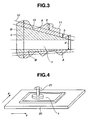
- FIG. 3 Illustrated in FIG. 3 are a substrate 1, a substrate surface 11, a least-square planes 12, and a surface 13 worked to be flat.
- the measurement data obtained in (1) are stored in a computer by assigning a flatness at a certain point within the substrate as height data. Based on these data, a material removal amount (designated A in FIG. 3 ) necessary to abrade away the substrate surface to be flat is computed for each of the front and back surfaces.
- a surface 13 which is worked to be flat for each of the front and back surfaces is parallel to the least square plane for each of the front and back surfaces and extends contiguous to the most recessed point in the measured surface.
- a parallelism of the substrate is computed. From the computed parallelism, a material removal amount (designated B in FIG. 3 ) is computed. The material removal amount is determined so as to equalize the thickness to the thinnest portion of the flattened substrate.
- FIG. 3 is a schematic exaggerated illustration of material removal portions so that removal portions A and B are readily understood. In this way, a material removal amount (I) at an ideal surface and point is determined from the measured flatness and parallelism of the front and back surfaces of the large-size synthetic quartz glass substrate stock.
- a large-size synthetic quartz glass substrate stock having substantially the same size, flatness and parallelism of front and back surfaces is worked by a first working tool, while the traverse rate, rotation, and material of the working tool are changed.
- the material removal amount is previously computed, from which a working profile is obtained on the basis of the material removal amount (I) at an ideal surface and point. Based on this, a material removal amount (II) at each surface and point by the first working tool and a traverse rate are computed.
- the substrate stock is abrasive worked by the first working tool based on the material removal amount (II) and traverse rate of (2).
- the first working tool has a diameter corresponding to 15 to 50%, preferably 30 to 45% of the diagonal length of the substrate stock. If the diameter of the first working tool is less than 15% of the substrate diagonal length, the working time is not fully reduced. If the diameter is more than 50% of the substrate diagonal length, flatness correction becomes less, which is uneconomical because the subsequent working time of a second working tool is prolonged.
- the first working tool preferably has a diameter of 250 to 800 mm, more preferably 400 to 600 mm.
- the first working tool preferably has a circular shape when operations such as attachment of abrasive cloth are considered.
- FIG. 4 is a schematic perspective view of a working apparatus.
- a substrate 1 is held on a platform 20, and a working tool 21 is movable over the substrate 1 in X and Y directions.
- the movement of the working tool 21 can be computer controlled.
- abrasive working is carried out while controlling the residence time of the working tool such that in an area requiring a large removal amount, the traverse rate of the working tool 21 is slowed to extend the residence time, and inversely in an area requiring a small removal amount, the traverse rate of the working tool 21 is increased to shorten the residence time.
- the substrate-holding platform 20 is preferably made of expanded polyurethane having a Shore A hardness of up to 80, more preferably 15 to 70, and a compressibility of 5 to 80%, more preferably 10 to 50%.
- a platform with a Shore A hardness of more than 80 may cause flaws to the substrate.
- With a compressibility of less than 5% the entire surface of the substrate may not be in close contact with the platform, and contact pressure may be locally increased to form defects at such sites.
- the working tool 21 is coupled to a rotating mechanism.
- the rotation count of the working tool 21 is preferably adjusted so that the abrasive slurry may not be splashed out of the apparatus, and specifically to 30 to 300 rpm, more preferably 30 to 120 rpm, although it may vary with the tool size.
- the working tool 21 is connected to the rotating shaft via a universal joint such that the tool may follow a slope of the substrate surface. Attached to the working tool 21 is an abrasive cloth which is typically polyurethane foam or nonwoven pad.
- Abrasive grains used herein are not particularly limited. Cerium oxide or colloidal silica grains are preferred as common abrasives. Abrasive grains preferably have an average particle size of 0.02 to 3 ⁇ m, more preferably 0.05 ⁇ m to 1 ⁇ m. Working is carried out while discharging the abrasive slurry from within the tool or immersing the substrate in the abrasive slurry.
- the preferred slurry contains 10 to 50% by weight, more preferably 10 to 40% by weight, further preferably 10 to 25% by weight of abrasive grains.
- the tool is oscillated while rotating so as to facilitate entry of the slurry to the site being worked. In this case, a working profile is previously examined under such conditions, based on which a traverse rate is computed.
- FIG. 5 is a perspective view showing how to traverse the working tool 21 across the substrate on the platform 20.
- Abrasive working may be carried out by traversing the working tool continuously parallel to X axis direction at a predetermined rate, then moving it over a certain pitch in Y axis direction, and so on as shown in FIG. 5 .
- the feed pitch in Y axis direction is preferably up to 30%, more preferably 10 to 25% of the diameter of the first working tool. If the pitch is more than 30% of the diameter, flatness correction may become less, which is uneconomical because the subsequent working time of a second working tool is prolonged.
- Abrasive working is carried out while the first working tool traverses across the surface of a large-size synthetic quartz glass substrate stock.
- the entire surface of the large-size synthetic quartz glass substrate stock cannot be worked at a time. Therefore, when only the first working tool is used, a difference may occur in some areas between an actual material removal amount and the material removal amount (I) at each ideal surface and point as computed from the measured flatness and parallelism of the front and back surfaces of the substrate stock.
- a second working tool may be used to abrade away the area which has not been fully abraded by the first working tool, for example, four corners of the substrate.
- a necessary material removal amount to be removed by the second working tool and traverse rate are computed so as to meet the material removal amount (I).
- I material removal amount
- a working profile achievable by the second working tool is previously examined, and further adjustment may be made based on that profile. In this way, the process carries out efficient working since accuracy measurement is not made after working by the first working tool.
- a necessary material removal amount to be removed by the second working tool and a traverse rate may be computed.
- the substrate is worked by the second working tool in accordance with the necessary material removal amount and traverse rate computed in (4).
- the size of the second working tool should be smaller than that of the first working tool.
- the second working tool preferably has a diameter corresponding to 10 to 40%, more preferably 15 to 30% of the diameter of the first working tool. If the diameter of the second working tool is less than 10% of the first working tool diameter, the flatness correcting effect may become greater, but a longer working time may be necessary, which is uneconomical. If the diameter of the second working tool is more than 40% of the first working tool diameter, the material removal amount may not be precisely controlled and the flatness correcting effect may become lessened.
- the second working tool preferably has a diameter of 25 mm to 320 mm, more preferably 100 mm to 200 mm. Like the first working tool, the second working tool preferably has a circular shape.
- the working process may be the same as the first working tool. Combination of the first working tool with the second working tool may prevent streaks from forming on the substrate. Further polishing step may follow. Without polishing step, however, the method is successful in producing a large-size synthetic quartz glass substrate having satisfactory flatness and parallelism.
- a large-size synthetic quartz glass substrate stock having a diagonal length of at least 1,000 mm is abrasively worked by the first working tool having a diameter of 15 to 50% of the substrate diagonal length, then further abrasively worked by the second working tool having a smaller diameter than the first working tool. More than one working step may be repeated for each of the first and second working tools.
- a large-size synthetic quartz glass substrate stock may be corrected for flatness and parallelism within a short time, producing a large-size synthetic quartz glass substrate having a high flatness and parallelism.
- the large-size synthetic quartz glass substrate has a diagonal length of at least 1,000 mm, preferably 1,500 mm to 2,500 mm.
- the shape of a large-size substrate may be square, rectangular, circular or otherwise. In the case of circular substrates, the diagonal length refers to the diameter.
- the thickness of a large-size substrate is not particularly limited, although it is preferably 5 mm to 50 mm, more preferably 10 mm to 20 mm.
- the large-size synthetic quartz glass substrate produced is highly flat as demonstrated by a flatness/diagonal length of up to 8 ⁇ 10 -6 , more preferably up to 6 ⁇ 10 -6 , and even more preferably up to 5 ⁇ 10 -6 .
- the flatness/diagonal length is typically at least 1 ⁇ 10 -6 , thought not limited thereto.
- the large-size synthetic quartz glass substrate produced has a parallelism of up to 50 ⁇ m, more preferably up to 30 ⁇ m, and even more preferably up to 10 ⁇ m. If the parallelism is more than 50 ⁇ m, a more burden may be imposed on correction operation for minimizing a variation of exposure gap when the substrate is mounted in the exposure tool.
- a large-size synthetic quartz glass substrate stock may be corrected for flatness and parallelism within a short time, and a large-size synthetic quartz glass substrate having a high flatness and parallelism may be produced.
- a large-size photomask may be prepared using the large-size synthetic quartz glass substrate.
- the large-size photomask may be used in panel exposure to achieve an improvement in CD accuracy and enable exposure of a fine feature pattern. This may eventually lead to improvements in the manufacture yield of panels.
- a synthetic quartz glass substrate stock was prepared by lapping a synthetic quartz glass substrate stock having a size of 850 mm ⁇ 1200 mm ⁇ 10.2 mm (thick) on a planetary motion double-side lapping machine using abrasives FO#1000 (Fujimi Abrasive Co., Ltd.).
- the substrate stock had a parallelism of 13 ⁇ m and a flatness of 50 ⁇ m.
- the flatness was measured by a flatness tester by Kuroda Precision Industries Ltd., and the parallelism was measured by a micrometer by Mitsutoyo Corp. From the measured data, a material removal amount at each relevant surface and point were determined.
- the substrate stock was mounted on a platform 20 in the apparatus shown in FIG. 4 .
- the platform 20 used was a waxless holding pad BP-102 of expanded polyurethane having Shore A hardness 66 and compressibility 25% (Fujibo Ehime Co., Ltd.).
- the first working tool was a stainless steel SUS304 disk having a diameter of 500 mm to which an abrasive cloth of polyurethane was attached.
- a slurry was prepared by suspending cerium oxide grains with an average particle size of 1 ⁇ m in water in a concentration of 20 wt%.
- a working profile was determined by providing a large-size synthetic quartz glass substrate stock having substantially the same size, flatness and parallelism on front and back surfaces and working it by the first working tool.
- the test revealed a working profile having a larger removal amount at the center and a smaller removal amount at the periphery of the tool as shown in FIG. 6 .
- a traverse rate of the first working tool was computed.
- Abrasive working was effected based on the traverse rate by traversing the first working tool continuously parallel to X axis and feeding in Y axis direction a pitch (100 mm) corresponding to 20% of the diameter of the first working tool.
- the first working tool was rotated at 60 rpm.
- the second working tool was a stainless steel SUS304 disk having a diameter of 150 mm to which an abrasive cloth of polyurethane was attached.
- a slurry was prepared by suspending cerium oxide grains with an average particle size of 1 ⁇ m in water in a concentration of 20 wt%.
- a necessary material removal amount to be removed by the second working tool was computed and a traverse rate of the second working tool was determined.
- the feed pitch in Y axis direction was 20% of the diameter of the second working tool, i.e., 30 mm.
- the second working tool was rotated at 150 rpm.
- the traverse rate of the second working tool in X axis direction was 30 mm/min at minimum.
- a traverse rate of the second working tool on a distinct area of the substrate was computed from a removal rate of that area.
- the front surface of the substrate was processed in this way, after which the back surface was similarly processed. The results are shown in Table 1.
- the working time was 26, provided that the working time passed when working was effected by the second working tool alone was 100. That is, working was completed within a time of about 1/4.
- the substrate thus worked had a flatness of 7.8 ⁇ m and a parallelism of 7.6 ⁇ m. Although the surface of a substrate which was worked by the second working tool alone bore streaks, the surface of the substrate worked in Example 1 displayed no streaks.
- Example 1 Substrates were worked as in Example 1 aside from using the first and second working tools of different size. The working time was reported, provided that the working time passed when working was effected by a single working tool having a diameter of 100 mm was 100.
- Table 1 Substrate size, mm ⁇ diagonal length, mm> Prior to working 1st working tool diameter, mm (diameter /diagonal length) 2nd working tool diameter, mm (diameter /1st tool diameter) working Time, % After working Flatness, ⁇ m Parallelism, ⁇ m Flatness, ⁇ m Parallelism, ⁇ m Flatness/ Diagonal length, ⁇ 10 -6
Landscapes
- Chemical & Material Sciences (AREA)
- Engineering & Computer Science (AREA)
- Geochemistry & Mineralogy (AREA)
- Life Sciences & Earth Sciences (AREA)
- Chemical Kinetics & Catalysis (AREA)
- General Chemical & Material Sciences (AREA)
- Mechanical Engineering (AREA)
- Materials Engineering (AREA)
- Organic Chemistry (AREA)
- Surface Treatment Of Glass (AREA)
- Finish Polishing, Edge Sharpening, And Grinding By Specific Grinding Devices (AREA)
- Preparing Plates And Mask In Photomechanical Process (AREA)
- Re-Forming, After-Treatment, Cutting And Transporting Of Glass Products (AREA)
Applications Claiming Priority (1)
| Application Number | Priority Date | Filing Date | Title |
|---|---|---|---|
| JP2009089043 | 2009-04-01 |
Publications (2)
| Publication Number | Publication Date |
|---|---|
| EP2236246A1 EP2236246A1 (en) | 2010-10-06 |
| EP2236246B1 true EP2236246B1 (en) | 2013-04-24 |
Family
ID=42235874
Family Applications (1)
| Application Number | Title | Priority Date | Filing Date |
|---|---|---|---|
| EP10250688.8A Active EP2236246B1 (en) | 2009-04-01 | 2010-03-31 | Method for producing large-size synthetic quartz glass substrate |
Country Status (7)
| Country | Link |
|---|---|
| US (1) | US8460061B2 (ko) |
| EP (1) | EP2236246B1 (ko) |
| JP (1) | JP5526895B2 (ko) |
| KR (1) | KR101571569B1 (ko) |
| CN (1) | CN101856805B (ko) |
| MY (1) | MY155088A (ko) |
| TW (1) | TWI488713B (ko) |
Families Citing this family (6)
| Publication number | Priority date | Publication date | Assignee | Title |
|---|---|---|---|---|
| JP5251861B2 (ja) * | 2009-12-28 | 2013-07-31 | 信越化学工業株式会社 | 合成石英ガラス基板の製造方法 |
| JPWO2014049844A1 (ja) * | 2012-09-28 | 2016-08-22 | 旭硝子株式会社 | 板状体の研磨方法及び板状体の研磨装置 |
| JP6668066B2 (ja) * | 2015-12-18 | 2020-03-18 | Hoya株式会社 | マスクブランク用基板の製造方法、マスクブランクの製造方法及び露光用マスクの製造方法 |
| MY186275A (en) | 2016-08-23 | 2021-07-02 | Shinetsu Chemical Co | Method for producing substrate |
| US10120424B2 (en) * | 2017-01-19 | 2018-11-06 | Intel Corporation | Conductive stress-relief washers in microelectronic assemblies |
| CN115446988A (zh) * | 2022-07-28 | 2022-12-09 | 陕西彩虹工业智能科技有限公司 | 一种柔性玻璃溢流砖的加工方法 |
Citations (8)
| Publication number | Priority date | Publication date | Assignee | Title |
|---|---|---|---|---|
| EP1333313A1 (en) * | 2002-01-31 | 2003-08-06 | Shin-Etsu Chemical Co., Ltd. | Large-sized substrate and method of producing the same |
| US20030186624A1 (en) * | 2002-03-29 | 2003-10-02 | Hoya Corporation | Method of determining a flatness of an electronic device substrate, method of producing the substrate, method of producing a mask blank, method of producing a transfer mask, polishing method, electronic device substrate, mask blank, transfer mask, and polishing apparatus |
| EP1566241A1 (en) * | 2004-02-18 | 2005-08-24 | Shin-Etsu Chemical Co., Ltd. | Method for preparing large-size substrate |
| US20070059608A1 (en) * | 2005-09-12 | 2007-03-15 | Asahi Glass Company, Ltd. | Photomask, photomask manufacturing method, and photomask processing device |
| EP1933204A2 (en) * | 2006-12-15 | 2008-06-18 | Shin-Etsu Chemical Co., Ltd. | Recycling of large-size photomask substrate |
| US20080261119A1 (en) * | 2005-06-17 | 2008-10-23 | Shuhei Ueda | Large-Size Glass Substrate For Photomask and Making Method, Computer-Readable Recording Medium, and Mother Glass Exposure Method |
| WO2009137685A2 (en) * | 2008-05-07 | 2009-11-12 | Zygo Corporation | Configuring of lapping and polishing machines |
| EP2156926A1 (en) * | 2007-06-05 | 2010-02-24 | Asahi Glass Company, Limited | Method of polishing glass substrate |
Family Cites Families (20)
| Publication number | Priority date | Publication date | Assignee | Title |
|---|---|---|---|---|
| US5599423A (en) * | 1995-06-30 | 1997-02-04 | Applied Materials, Inc. | Apparatus and method for simulating and optimizing a chemical mechanical polishing system |
| US5838447A (en) * | 1995-07-20 | 1998-11-17 | Ebara Corporation | Polishing apparatus including thickness or flatness detector |
| US6595831B1 (en) * | 1996-05-16 | 2003-07-22 | Ebara Corporation | Method for polishing workpieces using fixed abrasives |
| JP2000315665A (ja) * | 1999-04-29 | 2000-11-14 | Ebara Corp | 研磨方法及び装置 |
| US5989107A (en) * | 1996-05-16 | 1999-11-23 | Ebara Corporation | Method for polishing workpieces and apparatus therefor |
| JPH10329012A (ja) * | 1997-03-21 | 1998-12-15 | Canon Inc | 研磨装置および研磨方法 |
| JPH10329015A (ja) * | 1997-03-24 | 1998-12-15 | Canon Inc | 研磨装置および研磨方法 |
| US6439964B1 (en) * | 1999-10-12 | 2002-08-27 | Applied Materials, Inc. | Method of controlling a polishing machine |
| US7160739B2 (en) * | 2001-06-19 | 2007-01-09 | Applied Materials, Inc. | Feedback control of a chemical mechanical polishing device providing manipulation of removal rate profiles |
| JP4267333B2 (ja) * | 2002-01-31 | 2009-05-27 | 信越化学工業株式会社 | 大型合成石英ガラス基板の製造方法 |
| WO2004075276A1 (ja) * | 2003-02-18 | 2004-09-02 | Nikon Corporation | 研磨装置、研磨方法及び半導体デバイスの製造方法 |
| CN100490084C (zh) * | 2003-05-09 | 2009-05-20 | 三洋化成工业株式会社 | Cmp方法用研磨液及研磨方法 |
| TWI329779B (en) * | 2003-07-25 | 2010-09-01 | Shinetsu Chemical Co | Photomask blank substrate, photomask blank and photomask |
| US7086927B2 (en) * | 2004-03-09 | 2006-08-08 | Micron Technology, Inc. | Methods and systems for planarizing workpieces, e.g., microelectronic workpieces |
| SG160368A1 (en) * | 2005-03-08 | 2010-04-29 | Toyo Tire & Rubber Co | Polishing pad and process for producing the same |
| JP2006278977A (ja) * | 2005-03-30 | 2006-10-12 | Fujitsu Ltd | 半導体装置の製造方法および研磨方法 |
| JP2007001003A (ja) | 2005-05-27 | 2007-01-11 | Nikon Corp | 基板の製造方法 |
| JP4997815B2 (ja) | 2006-04-12 | 2012-08-08 | 旭硝子株式会社 | 高平坦かつ高平滑なガラス基板の作製方法 |
| JP5081643B2 (ja) * | 2008-01-23 | 2012-11-28 | 株式会社ディスコ | ウエーハの加工方法 |
| JP2009285774A (ja) * | 2008-05-29 | 2009-12-10 | Showa Denko Kk | 表面加工方法及び装置 |
-
2010
- 2010-03-18 JP JP2010062117A patent/JP5526895B2/ja active Active
- 2010-03-26 MY MYPI2010001356A patent/MY155088A/en unknown
- 2010-03-31 US US12/751,697 patent/US8460061B2/en active Active
- 2010-03-31 TW TW099109904A patent/TWI488713B/zh active
- 2010-03-31 KR KR1020100029058A patent/KR101571569B1/ko active IP Right Grant
- 2010-03-31 EP EP10250688.8A patent/EP2236246B1/en active Active
- 2010-04-01 CN CN201010190487.6A patent/CN101856805B/zh active Active
Patent Citations (8)
| Publication number | Priority date | Publication date | Assignee | Title |
|---|---|---|---|---|
| EP1333313A1 (en) * | 2002-01-31 | 2003-08-06 | Shin-Etsu Chemical Co., Ltd. | Large-sized substrate and method of producing the same |
| US20030186624A1 (en) * | 2002-03-29 | 2003-10-02 | Hoya Corporation | Method of determining a flatness of an electronic device substrate, method of producing the substrate, method of producing a mask blank, method of producing a transfer mask, polishing method, electronic device substrate, mask blank, transfer mask, and polishing apparatus |
| EP1566241A1 (en) * | 2004-02-18 | 2005-08-24 | Shin-Etsu Chemical Co., Ltd. | Method for preparing large-size substrate |
| US20080261119A1 (en) * | 2005-06-17 | 2008-10-23 | Shuhei Ueda | Large-Size Glass Substrate For Photomask and Making Method, Computer-Readable Recording Medium, and Mother Glass Exposure Method |
| US20070059608A1 (en) * | 2005-09-12 | 2007-03-15 | Asahi Glass Company, Ltd. | Photomask, photomask manufacturing method, and photomask processing device |
| EP1933204A2 (en) * | 2006-12-15 | 2008-06-18 | Shin-Etsu Chemical Co., Ltd. | Recycling of large-size photomask substrate |
| EP2156926A1 (en) * | 2007-06-05 | 2010-02-24 | Asahi Glass Company, Limited | Method of polishing glass substrate |
| WO2009137685A2 (en) * | 2008-05-07 | 2009-11-12 | Zygo Corporation | Configuring of lapping and polishing machines |
Also Published As
| Publication number | Publication date |
|---|---|
| KR101571569B1 (ko) | 2015-11-24 |
| US8460061B2 (en) | 2013-06-11 |
| KR20100109864A (ko) | 2010-10-11 |
| MY155088A (en) | 2015-08-28 |
| CN101856805B (zh) | 2014-07-02 |
| CN101856805A (zh) | 2010-10-13 |
| TWI488713B (zh) | 2015-06-21 |
| TW201105459A (en) | 2011-02-16 |
| JP2010254552A (ja) | 2010-11-11 |
| EP2236246A1 (en) | 2010-10-06 |
| US20100255761A1 (en) | 2010-10-07 |
| JP5526895B2 (ja) | 2014-06-18 |
Similar Documents
| Publication | Publication Date | Title |
|---|---|---|
| EP2236246B1 (en) | Method for producing large-size synthetic quartz glass substrate | |
| EP1333313B1 (en) | Method of producing a large-sized substrate | |
| TWI390616B (zh) | Semiconductor wafer manufacturing method | |
| KR100818683B1 (ko) | 경면 면취 웨이퍼, 경면 면취용 연마 클로스 및 경면 면취연마장치 및 방법 | |
| EP3287234B1 (en) | Method for producing substrate | |
| KR101143290B1 (ko) | 판상체의 연마 방법 및 그 장치 | |
| KR20140067886A (ko) | 판유리 등 워크의 주연부를 연마 테이프에 의해 연마하는 연마 장치 및 연마 방법 | |
| EP1566241B1 (en) | Method for preparing large-size substrate | |
| CN106965076B (zh) | 板状体的研磨方法及板状体的研磨装置 | |
| JP4267333B2 (ja) | 大型合成石英ガラス基板の製造方法 | |
| KR102657849B1 (ko) | 캐리어의 제조방법 및 웨이퍼의 양면 연마방법 | |
| JP4749700B2 (ja) | 研磨クロス,ウェーハ研磨装置及びウェーハ製造方法 | |
| JP6457802B2 (ja) | ガラス板の製造方法、および、ガラス板の製造装置 | |
| JP4340893B2 (ja) | 大型基板の製造方法 | |
| CN114585475A (zh) | 玻璃板的制造方法以及玻璃板 | |
| KR100809825B1 (ko) | 합성 석영 유리 기판 | |
| JPH09272049A (ja) | 工作物の両頭平面研削方法およびその両頭平面研削盤 |
Legal Events
| Date | Code | Title | Description |
|---|---|---|---|
| PUAI | Public reference made under article 153(3) epc to a published international application that has entered the european phase |
Free format text: ORIGINAL CODE: 0009012 |
|
| AK | Designated contracting states |
Kind code of ref document: A1 Designated state(s): AT BE BG CH CY CZ DE DK EE ES FI FR GB GR HR HU IE IS IT LI LT LU LV MC MK MT NL NO PL PT RO SE SI SK SM TR |
|
| AX | Request for extension of the european patent |
Extension state: AL BA ME RS |
|
| 17P | Request for examination filed |
Effective date: 20101103 |
|
| REG | Reference to a national code |
Ref country code: DE Ref legal event code: R079 Ref document number: 602010006544 Country of ref document: DE Free format text: PREVIOUS MAIN CLASS: B24B0037040000 Ipc: C03C0019000000 |
|
| RIC1 | Information provided on ipc code assigned before grant |
Ipc: C03C 19/00 20060101AFI20120927BHEP |
|
| GRAP | Despatch of communication of intention to grant a patent |
Free format text: ORIGINAL CODE: EPIDOSNIGR1 |
|
| GRAS | Grant fee paid |
Free format text: ORIGINAL CODE: EPIDOSNIGR3 |
|
| GRAA | (expected) grant |
Free format text: ORIGINAL CODE: 0009210 |
|
| AK | Designated contracting states |
Kind code of ref document: B1 Designated state(s): AT BE BG CH CY CZ DE DK EE ES FI FR GB GR HR HU IE IS IT LI LT LU LV MC MK MT NL NO PL PT RO SE SI SK SM TR |
|
| REG | Reference to a national code |
Ref country code: GB Ref legal event code: FG4D |
|
| REG | Reference to a national code |
Ref country code: CH Ref legal event code: EP |
|
| REG | Reference to a national code |
Ref country code: AT Ref legal event code: REF Ref document number: 608530 Country of ref document: AT Kind code of ref document: T Effective date: 20130515 |
|
| REG | Reference to a national code |
Ref country code: IE Ref legal event code: FG4D |
|
| REG | Reference to a national code |
Ref country code: DE Ref legal event code: R096 Ref document number: 602010006544 Country of ref document: DE Effective date: 20130620 |
|
| REG | Reference to a national code |
Ref country code: AT Ref legal event code: MK05 Ref document number: 608530 Country of ref document: AT Kind code of ref document: T Effective date: 20130424 |
|
| REG | Reference to a national code |
Ref country code: LT Ref legal event code: MG4D |
|
| REG | Reference to a national code |
Ref country code: NL Ref legal event code: VDEP Effective date: 20130424 |
|
| PG25 | Lapsed in a contracting state [announced via postgrant information from national office to epo] |
Ref country code: PT Free format text: LAPSE BECAUSE OF FAILURE TO SUBMIT A TRANSLATION OF THE DESCRIPTION OR TO PAY THE FEE WITHIN THE PRESCRIBED TIME-LIMIT Effective date: 20130826 Ref country code: ES Free format text: LAPSE BECAUSE OF FAILURE TO SUBMIT A TRANSLATION OF THE DESCRIPTION OR TO PAY THE FEE WITHIN THE PRESCRIBED TIME-LIMIT Effective date: 20130804 Ref country code: GR Free format text: LAPSE BECAUSE OF FAILURE TO SUBMIT A TRANSLATION OF THE DESCRIPTION OR TO PAY THE FEE WITHIN THE PRESCRIBED TIME-LIMIT Effective date: 20130725 Ref country code: SE Free format text: LAPSE BECAUSE OF FAILURE TO SUBMIT A TRANSLATION OF THE DESCRIPTION OR TO PAY THE FEE WITHIN THE PRESCRIBED TIME-LIMIT Effective date: 20130424 Ref country code: SI Free format text: LAPSE BECAUSE OF FAILURE TO SUBMIT A TRANSLATION OF THE DESCRIPTION OR TO PAY THE FEE WITHIN THE PRESCRIBED TIME-LIMIT Effective date: 20130424 Ref country code: NO Free format text: LAPSE BECAUSE OF FAILURE TO SUBMIT A TRANSLATION OF THE DESCRIPTION OR TO PAY THE FEE WITHIN THE PRESCRIBED TIME-LIMIT Effective date: 20130724 Ref country code: AT Free format text: LAPSE BECAUSE OF FAILURE TO SUBMIT A TRANSLATION OF THE DESCRIPTION OR TO PAY THE FEE WITHIN THE PRESCRIBED TIME-LIMIT Effective date: 20130424 Ref country code: LT Free format text: LAPSE BECAUSE OF FAILURE TO SUBMIT A TRANSLATION OF THE DESCRIPTION OR TO PAY THE FEE WITHIN THE PRESCRIBED TIME-LIMIT Effective date: 20130424 Ref country code: IS Free format text: LAPSE BECAUSE OF FAILURE TO SUBMIT A TRANSLATION OF THE DESCRIPTION OR TO PAY THE FEE WITHIN THE PRESCRIBED TIME-LIMIT Effective date: 20130824 Ref country code: BE Free format text: LAPSE BECAUSE OF FAILURE TO SUBMIT A TRANSLATION OF THE DESCRIPTION OR TO PAY THE FEE WITHIN THE PRESCRIBED TIME-LIMIT Effective date: 20130424 Ref country code: FI Free format text: LAPSE BECAUSE OF FAILURE TO SUBMIT A TRANSLATION OF THE DESCRIPTION OR TO PAY THE FEE WITHIN THE PRESCRIBED TIME-LIMIT Effective date: 20130424 |
|
| PG25 | Lapsed in a contracting state [announced via postgrant information from national office to epo] |
Ref country code: LV Free format text: LAPSE BECAUSE OF FAILURE TO SUBMIT A TRANSLATION OF THE DESCRIPTION OR TO PAY THE FEE WITHIN THE PRESCRIBED TIME-LIMIT Effective date: 20130424 Ref country code: CY Free format text: LAPSE BECAUSE OF FAILURE TO SUBMIT A TRANSLATION OF THE DESCRIPTION OR TO PAY THE FEE WITHIN THE PRESCRIBED TIME-LIMIT Effective date: 20130424 Ref country code: HR Free format text: LAPSE BECAUSE OF FAILURE TO SUBMIT A TRANSLATION OF THE DESCRIPTION OR TO PAY THE FEE WITHIN THE PRESCRIBED TIME-LIMIT Effective date: 20130424 Ref country code: PL Free format text: LAPSE BECAUSE OF FAILURE TO SUBMIT A TRANSLATION OF THE DESCRIPTION OR TO PAY THE FEE WITHIN THE PRESCRIBED TIME-LIMIT Effective date: 20130424 Ref country code: BG Free format text: LAPSE BECAUSE OF FAILURE TO SUBMIT A TRANSLATION OF THE DESCRIPTION OR TO PAY THE FEE WITHIN THE PRESCRIBED TIME-LIMIT Effective date: 20130724 |
|
| PG25 | Lapsed in a contracting state [announced via postgrant information from national office to epo] |
Ref country code: SK Free format text: LAPSE BECAUSE OF FAILURE TO SUBMIT A TRANSLATION OF THE DESCRIPTION OR TO PAY THE FEE WITHIN THE PRESCRIBED TIME-LIMIT Effective date: 20130424 Ref country code: CZ Free format text: LAPSE BECAUSE OF FAILURE TO SUBMIT A TRANSLATION OF THE DESCRIPTION OR TO PAY THE FEE WITHIN THE PRESCRIBED TIME-LIMIT Effective date: 20130424 Ref country code: EE Free format text: LAPSE BECAUSE OF FAILURE TO SUBMIT A TRANSLATION OF THE DESCRIPTION OR TO PAY THE FEE WITHIN THE PRESCRIBED TIME-LIMIT Effective date: 20130424 Ref country code: DK Free format text: LAPSE BECAUSE OF FAILURE TO SUBMIT A TRANSLATION OF THE DESCRIPTION OR TO PAY THE FEE WITHIN THE PRESCRIBED TIME-LIMIT Effective date: 20130424 |
|
| PG25 | Lapsed in a contracting state [announced via postgrant information from national office to epo] |
Ref country code: IT Free format text: LAPSE BECAUSE OF FAILURE TO SUBMIT A TRANSLATION OF THE DESCRIPTION OR TO PAY THE FEE WITHIN THE PRESCRIBED TIME-LIMIT Effective date: 20130424 Ref country code: NL Free format text: LAPSE BECAUSE OF FAILURE TO SUBMIT A TRANSLATION OF THE DESCRIPTION OR TO PAY THE FEE WITHIN THE PRESCRIBED TIME-LIMIT Effective date: 20130424 Ref country code: RO Free format text: LAPSE BECAUSE OF FAILURE TO SUBMIT A TRANSLATION OF THE DESCRIPTION OR TO PAY THE FEE WITHIN THE PRESCRIBED TIME-LIMIT Effective date: 20130424 |
|
| PLBE | No opposition filed within time limit |
Free format text: ORIGINAL CODE: 0009261 |
|
| STAA | Information on the status of an ep patent application or granted ep patent |
Free format text: STATUS: NO OPPOSITION FILED WITHIN TIME LIMIT |
|
| 26N | No opposition filed |
Effective date: 20140127 |
|
| REG | Reference to a national code |
Ref country code: DE Ref legal event code: R097 Ref document number: 602010006544 Country of ref document: DE Effective date: 20140127 |
|
| PG25 | Lapsed in a contracting state [announced via postgrant information from national office to epo] |
Ref country code: LU Free format text: LAPSE BECAUSE OF FAILURE TO SUBMIT A TRANSLATION OF THE DESCRIPTION OR TO PAY THE FEE WITHIN THE PRESCRIBED TIME-LIMIT Effective date: 20140331 |
|
| REG | Reference to a national code |
Ref country code: CH Ref legal event code: PL |
|
| REG | Reference to a national code |
Ref country code: IE Ref legal event code: MM4A |
|
| PG25 | Lapsed in a contracting state [announced via postgrant information from national office to epo] |
Ref country code: CH Free format text: LAPSE BECAUSE OF NON-PAYMENT OF DUE FEES Effective date: 20140331 Ref country code: LI Free format text: LAPSE BECAUSE OF NON-PAYMENT OF DUE FEES Effective date: 20140331 Ref country code: IE Free format text: LAPSE BECAUSE OF NON-PAYMENT OF DUE FEES Effective date: 20140331 |
|
| REG | Reference to a national code |
Ref country code: FR Ref legal event code: PLFP Year of fee payment: 7 |
|
| PG25 | Lapsed in a contracting state [announced via postgrant information from national office to epo] |
Ref country code: MT Free format text: LAPSE BECAUSE OF FAILURE TO SUBMIT A TRANSLATION OF THE DESCRIPTION OR TO PAY THE FEE WITHIN THE PRESCRIBED TIME-LIMIT Effective date: 20130424 |
|
| PG25 | Lapsed in a contracting state [announced via postgrant information from national office to epo] |
Ref country code: SM Free format text: LAPSE BECAUSE OF FAILURE TO SUBMIT A TRANSLATION OF THE DESCRIPTION OR TO PAY THE FEE WITHIN THE PRESCRIBED TIME-LIMIT Effective date: 20130424 |
|
| PG25 | Lapsed in a contracting state [announced via postgrant information from national office to epo] |
Ref country code: MC Free format text: LAPSE BECAUSE OF FAILURE TO SUBMIT A TRANSLATION OF THE DESCRIPTION OR TO PAY THE FEE WITHIN THE PRESCRIBED TIME-LIMIT Effective date: 20130424 |
|
| PG25 | Lapsed in a contracting state [announced via postgrant information from national office to epo] |
Ref country code: HU Free format text: LAPSE BECAUSE OF FAILURE TO SUBMIT A TRANSLATION OF THE DESCRIPTION OR TO PAY THE FEE WITHIN THE PRESCRIBED TIME-LIMIT; INVALID AB INITIO Effective date: 20100331 Ref country code: TR Free format text: LAPSE BECAUSE OF FAILURE TO SUBMIT A TRANSLATION OF THE DESCRIPTION OR TO PAY THE FEE WITHIN THE PRESCRIBED TIME-LIMIT Effective date: 20130424 |
|
| REG | Reference to a national code |
Ref country code: FR Ref legal event code: PLFP Year of fee payment: 8 |
|
| REG | Reference to a national code |
Ref country code: FR Ref legal event code: PLFP Year of fee payment: 9 |
|
| PG25 | Lapsed in a contracting state [announced via postgrant information from national office to epo] |
Ref country code: MK Free format text: LAPSE BECAUSE OF FAILURE TO SUBMIT A TRANSLATION OF THE DESCRIPTION OR TO PAY THE FEE WITHIN THE PRESCRIBED TIME-LIMIT Effective date: 20130424 |
|
| PGFP | Annual fee paid to national office [announced via postgrant information from national office to epo] |
Ref country code: FR Payment date: 20230208 Year of fee payment: 14 |
|
| PGFP | Annual fee paid to national office [announced via postgrant information from national office to epo] |
Ref country code: DE Payment date: 20240206 Year of fee payment: 15 Ref country code: GB Payment date: 20240208 Year of fee payment: 15 |