EP2236070A2 - Aspirateur doté d'un dispositif de nervure - Google Patents
Aspirateur doté d'un dispositif de nervure Download PDFInfo
- Publication number
- EP2236070A2 EP2236070A2 EP10155863A EP10155863A EP2236070A2 EP 2236070 A2 EP2236070 A2 EP 2236070A2 EP 10155863 A EP10155863 A EP 10155863A EP 10155863 A EP10155863 A EP 10155863A EP 2236070 A2 EP2236070 A2 EP 2236070A2
- Authority
- EP
- European Patent Office
- Prior art keywords
- rib
- vacuum cleaner
- suction air
- main filter
- air stream
- Prior art date
- Legal status (The legal status is an assumption and is not a legal conclusion. Google has not performed a legal analysis and makes no representation as to the accuracy of the status listed.)
- Granted
Links
- 239000000463 material Substances 0.000 claims abstract description 38
- 239000000428 dust Substances 0.000 claims abstract description 23
- 238000000926 separation method Methods 0.000 claims abstract description 10
- 239000000126 substance Substances 0.000 claims description 35
- 239000002245 particle Substances 0.000 claims description 28
- 235000019645 odor Nutrition 0.000 description 23
- 150000001875 compounds Chemical class 0.000 description 16
- 238000004519 manufacturing process Methods 0.000 description 8
- 230000008901 benefit Effects 0.000 description 7
- 238000011144 upstream manufacturing Methods 0.000 description 7
- OKTJSMMVPCPJKN-UHFFFAOYSA-N Carbon Chemical compound [C] OKTJSMMVPCPJKN-UHFFFAOYSA-N 0.000 description 6
- 230000000694 effects Effects 0.000 description 6
- 239000002304 perfume Substances 0.000 description 6
- 238000011161 development Methods 0.000 description 5
- 230000018109 developmental process Effects 0.000 description 5
- 239000004744 fabric Substances 0.000 description 5
- 238000001746 injection moulding Methods 0.000 description 5
- 235000005979 Citrus limon Nutrition 0.000 description 4
- 244000131522 Citrus pyriformis Species 0.000 description 4
- 238000004140 cleaning Methods 0.000 description 3
- 230000006378 damage Effects 0.000 description 3
- 230000000873 masking effect Effects 0.000 description 3
- 238000011045 prefiltration Methods 0.000 description 3
- CURLTUGMZLYLDI-UHFFFAOYSA-N Carbon dioxide Chemical compound O=C=O CURLTUGMZLYLDI-UHFFFAOYSA-N 0.000 description 2
- 241000218691 Cupressaceae Species 0.000 description 2
- 241000196324 Embryophyta Species 0.000 description 2
- 235000010254 Jasminum officinale Nutrition 0.000 description 2
- 240000005385 Jasminum sambac Species 0.000 description 2
- 244000178231 Rosmarinus officinalis Species 0.000 description 2
- 208000027418 Wounds and injury Diseases 0.000 description 2
- 230000009471 action Effects 0.000 description 2
- 239000004480 active ingredient Substances 0.000 description 2
- 239000000686 essence Substances 0.000 description 2
- 239000003205 fragrance Substances 0.000 description 2
- 239000004615 ingredient Substances 0.000 description 2
- 208000014674 injury Diseases 0.000 description 2
- 244000005700 microbiome Species 0.000 description 2
- 230000009467 reduction Effects 0.000 description 2
- 238000007789 sealing Methods 0.000 description 2
- 239000000243 solution Substances 0.000 description 2
- 235000013311 vegetables Nutrition 0.000 description 2
- 241000894006 Bacteria Species 0.000 description 1
- 238000005299 abrasion Methods 0.000 description 1
- 239000000654 additive Substances 0.000 description 1
- 230000000996 additive effect Effects 0.000 description 1
- 239000003463 adsorbent Substances 0.000 description 1
- 230000015572 biosynthetic process Effects 0.000 description 1
- 239000011449 brick Substances 0.000 description 1
- 229910002092 carbon dioxide Inorganic materials 0.000 description 1
- 239000001569 carbon dioxide Substances 0.000 description 1
- 230000008859 change Effects 0.000 description 1
- 239000007795 chemical reaction product Substances 0.000 description 1
- 239000013078 crystal Substances 0.000 description 1
- 238000000354 decomposition reaction Methods 0.000 description 1
- 230000002950 deficient Effects 0.000 description 1
- 230000001419 dependent effect Effects 0.000 description 1
- 238000000151 deposition Methods 0.000 description 1
- 239000000945 filler Substances 0.000 description 1
- 238000001914 filtration Methods 0.000 description 1
- 231100000206 health hazard Toxicity 0.000 description 1
- 238000010348 incorporation Methods 0.000 description 1
- 230000003993 interaction Effects 0.000 description 1
- 238000005304 joining Methods 0.000 description 1
- 230000000670 limiting effect Effects 0.000 description 1
- VUZPPFZMUPKLLV-UHFFFAOYSA-N methane;hydrate Chemical compound C.O VUZPPFZMUPKLLV-UHFFFAOYSA-N 0.000 description 1
- 238000006386 neutralization reaction Methods 0.000 description 1
- 230000003472 neutralizing effect Effects 0.000 description 1
- 230000009965 odorless effect Effects 0.000 description 1
- 238000003825 pressing Methods 0.000 description 1
- 239000000047 product Substances 0.000 description 1
- 230000000717 retained effect Effects 0.000 description 1
- 238000001179 sorption measurement Methods 0.000 description 1
- 230000007704 transition Effects 0.000 description 1
- 238000009827 uniform distribution Methods 0.000 description 1
- 238000010407 vacuum cleaning Methods 0.000 description 1
- XLYOFNOQVPJJNP-UHFFFAOYSA-N water Substances O XLYOFNOQVPJJNP-UHFFFAOYSA-N 0.000 description 1
- 230000036642 wellbeing Effects 0.000 description 1
Images

Classifications
-
- A—HUMAN NECESSITIES
- A47—FURNITURE; DOMESTIC ARTICLES OR APPLIANCES; COFFEE MILLS; SPICE MILLS; SUCTION CLEANERS IN GENERAL
- A47L—DOMESTIC WASHING OR CLEANING; SUCTION CLEANERS IN GENERAL
- A47L9/00—Details or accessories of suction cleaners, e.g. mechanical means for controlling the suction or for effecting pulsating action; Storing devices specially adapted to suction cleaners or parts thereof; Carrying-vehicles specially adapted for suction cleaners
- A47L9/10—Filters; Dust separators; Dust removal; Automatic exchange of filters
-
- A—HUMAN NECESSITIES
- A47—FURNITURE; DOMESTIC ARTICLES OR APPLIANCES; COFFEE MILLS; SPICE MILLS; SUCTION CLEANERS IN GENERAL
- A47L—DOMESTIC WASHING OR CLEANING; SUCTION CLEANERS IN GENERAL
- A47L7/00—Suction cleaners adapted for additional purposes; Tables with suction openings for cleaning purposes; Containers for cleaning articles by suction; Suction cleaners adapted to cleaning of brushes; Suction cleaners adapted to taking-up liquids
- A47L7/0061—Suction cleaners adapted for additional purposes; Tables with suction openings for cleaning purposes; Containers for cleaning articles by suction; Suction cleaners adapted to cleaning of brushes; Suction cleaners adapted to taking-up liquids adapted for disinfecting or sterilising
-
- A—HUMAN NECESSITIES
- A47—FURNITURE; DOMESTIC ARTICLES OR APPLIANCES; COFFEE MILLS; SPICE MILLS; SUCTION CLEANERS IN GENERAL
- A47L—DOMESTIC WASHING OR CLEANING; SUCTION CLEANERS IN GENERAL
- A47L7/00—Suction cleaners adapted for additional purposes; Tables with suction openings for cleaning purposes; Containers for cleaning articles by suction; Suction cleaners adapted to cleaning of brushes; Suction cleaners adapted to taking-up liquids
- A47L7/04—Suction cleaners adapted for additional purposes; Tables with suction openings for cleaning purposes; Containers for cleaning articles by suction; Suction cleaners adapted to cleaning of brushes; Suction cleaners adapted to taking-up liquids for using the exhaust air for other purposes, e.g. for distribution of chemicals in a room, for sterilisation of the air
-
- A—HUMAN NECESSITIES
- A47—FURNITURE; DOMESTIC ARTICLES OR APPLIANCES; COFFEE MILLS; SPICE MILLS; SUCTION CLEANERS IN GENERAL
- A47L—DOMESTIC WASHING OR CLEANING; SUCTION CLEANERS IN GENERAL
- A47L9/00—Details or accessories of suction cleaners, e.g. mechanical means for controlling the suction or for effecting pulsating action; Storing devices specially adapted to suction cleaners or parts thereof; Carrying-vehicles specially adapted for suction cleaners
- A47L9/10—Filters; Dust separators; Dust removal; Automatic exchange of filters
- A47L9/12—Dry filters
- A47L9/122—Dry filters flat
-
- B—PERFORMING OPERATIONS; TRANSPORTING
- B01—PHYSICAL OR CHEMICAL PROCESSES OR APPARATUS IN GENERAL
- B01D—SEPARATION
- B01D46/00—Filters or filtering processes specially modified for separating dispersed particles from gases or vapours
- B01D46/0002—Casings; Housings; Frame constructions
- B01D46/0004—Details of removable closures, lids, caps or filter heads
Definitions
- the present invention relates to a vacuum cleaner with a motor-blower unit for generating a suction air flow, with a Staubabscheideiki for depositing dust, and with a rib means having at least a first rib, wherein a first rib portion of the first rib and a second rib portion of the first or a second rib of the rib means is arcuate.
- a filter cartridge for a vacuum cleaner which consists of a cassette-like base frame and a cover grid hinged therein.
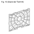
- a motor protection filter is known from the prior art, which has a rib body consisting of concentric circles with superimposed ribs, as in Fig. 10 shown. This ribbed body has different rib heights, the ribbed edges lying in different planes.
- the invention has for its object to provide a comparison with the prior art improved and cost-effective fin device for a vacuum cleaner.
- a conspicuous geometry for the user should be made possible with simple and material-saving means.
- the rib means a support and / or safety function.
- a vacuum cleaner is understood to mean appliances powered by electrical energy to absorb dust, including both mains operated and battery or cordless appliances.
- a Staubabscheidetician is a device in which the dirt-laden suction air can be cleaned of the dirt.
- such a Staubabscheidetician have a filter bag with or without basket, or a centrifugal separator.
- the Staubabscheidetician can be located in a dust chamber.
- a rib according to the invention may take the form of a web and / or a wall, and may be divided into rib sections. In particular, there is an oval, elliptical, circular, wave, curve, drop and / or cloud-shaped rib of at least one arc-shaped rib section.
- the cross section of a rib may be round, oval, rectangular or a combination thereof.
- at least one rib can form a lattice structure.
- Two rib sections contact each other if they have at least one common point.
- the rib sections can touch each other tangentially, intersect, intersect, penetrate or butt against each other.
- the vacuum cleaner according to the invention can give the user the impression of a particularly clean vacuum cleaner.
- This counter-impression to a dirty because of the usual use vacuum cleaner can enhance the subjective perceived cleaning effect of the vacuum cleaner even further.
- the mechanical stability of the rib device can be increased by the contact according to the invention of the rib-shaped rib sections, and a torsionally rigid rib device can be achieved.
- a safety function such as, for example, an interventional protection
- an interventional protection which can be achieved, in particular, by the design of the ribs according to the invention
- At least the first, the second and / or another rib portion forms a circular arc.
- the first rib portion disposed on the first rib may contact the second rib portion located on the first or second rib.
- the invention further development is preferably provided that at least the first, the second and / or another rib is circular.
- the first rib may be formed circular, wherein the first rib portion may correspond to the entire rib, and the second rib portion of the second rib touches the first rib portion.
- a further rib is of circular design, which particularly preferably contacts the first and / or the second rib section.
- all the ribs of the rib device are circular.
- at least two ribs touch each other.
- At least the first, the second or another rib has a constant rib height.
- All ribs of the rib means have a constant rib height.
- a rib having a constant rib height may advantageously have a uniform rib height in a spatial direction. As a result, it can be achieved that the fin device is easy to manufacture, and their space requirement can be reduced.
- Embodiments of the invention are also possible in which a rib has different rib heights.
- the constant rib height of one of the ribs differs from the constant rib height of another rib. More preferably, the constant rib height of the first differs from the constant rib height of the second rib. Particularly preferably, the constant rib height of a rib differs from the constant rib height of another rib, wherein both ribs have at least one arc-shaped rib portion, and both rib portions touch.
- the rib having the largest fin height may be used as the grip surface for removing the rib means from the vacuum cleaner.
- a particularly preferred rib device has at least one holding frame.
- the ribs are arranged on the holding frame.
- a holding frame can be made a mechanical attachment to parts or functional parts of the vacuum cleaner and / or the mechanical stability of the rib means can be increased.
- a particularly reliable connection of the rib device with the vacuum cleaner can be made possible by a support frame.
- the holding frame made of plastic, whereby the mechanical strength of the rib device can be further increased.
- simple and inexpensive production methods such as e.g. Plastic injection molding process can be used.
- the invention further development is preferably provided that at least one rib edge protrudes from the rib means.
- the appearance of the rib device can be made more apparent, since the user can jump a protruding rib edge faster in the eye.
- loose and / or movable parts of the vacuum cleaner such as a Staubabscheideiki be better supported.
- a rib with a rib edge protruding from the rib device can be used as a gripping surface for removing the rib device from the vacuum cleaner.
- the rib edges projecting from the rib device lie in at least two planes.
- the rib edges protruding from the holding frame lie in at least two planes. This can be achieved by at least the constant rib height of one of the ribs being different from the constant rib height of another rib, or by having at least one rib having different rib heights.
- the invention also includes combinations of these two possibilities.
- the fin means When the fin means is disposed in the suction air stream and is sent to a dust separation unit, e.g. a dust bag, downstream in the direction of the suction air stream, thereby advantageously a flat concern and / or suction of the dust bag can be avoided to the rib means. Due to the different heights in which the ribs end, gaps can be created through which suction air can flow in order to avoid a loss of suction power can. Furthermore, flow through the rib device can be reliably achieved even when the dust bag is full.
- the rib edge of a rib lies in at least two planes, which may be e.g. can be realized by a wave-like or wedge-shaped contour of the rib. Most preferably, the shape of the rib and / or the level transitions are rounded to prevent damage, e.g. a dust bag, as well as to avoid injury to the user.
- the rib means is arranged in the suction air flow.
- the ribs extend in their rib height along the suction air flow.
- the rib device is arranged in the suction air flow, it can be achieved that particles stick to at least one rib of the rib device because of their size, and thus be removed from the suction air flow.
- the rib device is arranged in front of moving or live parts of the vacuum cleaner, such as the motor-blower unit, in order to avoid engagement and thus injury to the user as an interventional protection.
- a preferred rib device is a dispensing device for dispensing substances into the suction air flow.
- the rib device emits odor-masking and / or odor-neutralizing substances into the suction air stream.
- the air can be freed from malodors, and the user subjectively perceived cleaning effect of the vacuum cleaner can be further increased.
- the rib means are substances consisting of inclusion compounds in the suction air stream.
- Inclusion compounds are to be understood as compounds which, in cavities of their lattice, have a guest component, such as e.g. Absorb, store and / or trap odor particles.
- the grating of the inclusion compound can be channel-like and / or layer-like, and / or a crystal lattice. Of course, other grid forms are conceivable.
- the rib device gives substances consisting of cage compounds, so-called clathrates, into the suction air stream.
- Cage compounds or clathrates are compounds in which cavities are enclosed in a cage-like manner by the atomic and / or atomic groups of the compound, so that a guest component can be incorporated into the cavities.
- a clathrate is a special type of inclusion compound. Atoms or molecules of the clathrates may be arranged to surround at least one cavity and may constitute a cage for that enclosed cavity.
- simple molecular structures, particularly preferably odor particles can be incorporated into the cage-like cavities of the clathrates be particularly preferably mechanically held in the cavity, the odor particles.
- a clathrate particularly preferred according to the invention may be e.g. be acquired through the company "et-project” with the trade name "SinoAir®".
- This ingredient consists mainly of plant clathrates.
- the active ingredient is combined with essential essences in a gel derived from vegetable substances.
- the inclusion compounds and the clathrates are odor-neutralizing substances, since odor particles can be incorporated into the cavities of the inclusion compound and / or the clathrates. In this way it can be achieved that the odor particles are no longer perceptible, although they are still present in the air, enclosed by the inclusion compound and / or the clathrates.
- the rib device emits odor-covering substances, such as eg perfume substances, into the suction air stream.
- odor-covering substances such as eg perfume substances
- perfumes such as rosemary, cypress, jasmine and / or lemon use.
- odor masking substances such as rosemary, cypress, jasmine and / or lemon use.
- the combination of odor-neutralizing and odor-masking substances thus better conveys to the user the impression of a functioning rib device.
- a particularly pleasant smell here lemon fragrance has been found, which is particularly preferably used.
- the rib device removes particles from the suction air stream, and thus can be used as a filter.
- the rib means can also extract moisture from the suction air flow.
- combinations of the embodiments of the invention are conceivable for this purpose, in which the rib device removes particles from the suction air flow and at the same time emits substances into the suction air flow. As a result, it is advantageously possible to combine filtering of particles from the suction air stream with control of odors.
- the rib device has an additional material in order to remove particles from the suction air flow and / or to discharge substances into the suction air flow.
- the additional material is arranged in the holding frame of the rib device.
- the additional material contains odor-neutralizing and / or odor-masking substances.
- the odor-neutralizing and / or odor-masking substances are delivered to the suction air stream.
- the additional material particularly preferably contains adsorbent materials, eg activated carbon, and / or inclusion compounds, and / or clathrates and / or combinations thereof.
- Activated carbon and clathrates may have the advantage that they impede the suction air flow only in a small way and also allow a long service life of the rib device of eg about one year.
- the additional material contains particularly preferably microorganisms, particularly preferably bacteria and / or other microorganisms.
- microorganisms particularly preferably bacteria and / or other microorganisms.
- the additional material has a plurality, preferably at least three, layers of equal or different thickness, which are preferably arranged perpendicularly in the direction of the suction air flow.
- the additional material of the rib device is held in a subframe.
- a particularly preferred subframe is divided into a plurality, preferably at least four chambers of the same or different size.
- the additional material between two, extending over the window, air-permeable substances in the subframe is held.
- the additional material is granular, which is particularly well storable in the subframe.
- Embodiments of the invention are also conceivable in which the additional material of the rib device is held in the retaining frame of the rib device via the auxiliary frame.
- the subframe is particularly preferably fastened to the holding frame of the rib device via a positive connection, for example a snap or latching connection.
- a universal support frame which can be arranged on fixed, movable or replaceable parts of the vacuum cleaner, allows become.
- an additional material which is formed, for example, granular or pourable, are made possible.
- the holding frame has a plurality of chambers, a uniform distribution of the additional material can be achieved even with a vertical arrangement of the rib means. This can allow a uniform flow through the additional material.
- a removal of particles from the suction air stream can be combined with a control of odors.
- various types of additional material can be filled into different chambers in order to make the functionality of the rib device even more extensive.
- This embodiment of the rib device with a subframe can further have the advantage that both odor neutralizing and odor masking substances, for example, to combat odors and for dispensing perfumes, as a supplementary material can be particularly easily introduced into the rib device to during normal operation of the vacuum cleaner in the suction air can be delivered.
- Another achievable advantage may be that only the sub-frame and not the entire rib means must be replaced to replace used additional material with new additional material.
- the rib device has at least one bypass opening in order to connect a first space in front of the rib device to a second space downstream of the rib device.
- the bypass opening according to the invention, it can be achieved that during normal operation of the vacuum cleaner at least part of the suction air flow flows through the additional material, and the other part of the suction air flow flows past the additional material through the bypass opening.
- a portion of the suction air can pass through the fin device unhindered, which can result in a lower pressure loss at the fin device.
- the air power of the vacuum cleaner can thus be reduced only imperceptibly by the rib means.
- an approximately constant suction power of the vacuum cleaner can be achieved even with an added fin device.
- Another achievable advantage of the rib device according to the invention can be that the duration of action of the rib device can extend, which means that it must be changed less frequently.
- the rib means of the Staubabscheideiki is downstream in the direction of the suction air flow.
- the fin means is disposed in the already dust-removed suction air, whereby a more efficient operation of the fin means can be made possible because the number of particles flowing through the fin means has already been reduced by the dust separation unit.
- the rib device is arranged as a filter for removing particles from the suction air stream and / or as a dispenser for dispensing substances in the suction air stream in the vacuum cleaner.
- the rib structure is a motor protection filter and / or an exhaust filter.
- the rib means can also be used without filter or dispensing function e.g.
- the fin device downstream of the dust separation unit can be easily visually recognized by the user and easily accessible.
- embodiments of the invention are also possible in which the rib device of the dust separation unit is upstream or intermediate in the direction of the suction air flow.
- the vacuum cleaner has a main filter, with which the rib device is connectable.
- a main filter is understood to mean a filter of the vacuum cleaner, which is arranged in the suction air flow and which is upstream, intermediate or downstream of the dust separation unit.
- a main filter can be either a pre-filter, an intermediate filter or an after-filter, which can filter different sized dust particles from the suction air stream depending on the arrangement in the suction air flow.
- an intermediate filter may be a so-called motor protection filter, which may be located in or in front of a suction opening of the motor-blower unit.
- the motor protection filter is particularly preferably downstream of the Staubabscheidetician to provide protection of the engine fan unit from particles in the intake air in the absence of Staubabscheidetician, for example, caused by incorrect operation. Further, a motor protection filter may protect the motor blower unit from particles that have not been picked up by the dust collection unit.
- a post-filter can be understood a blow-out, which can filter the exhaust air flow at the outlet from a vacuum cleaner housing.
- An exhaust filter can advantageously from a Vacuum Cleaner exiting air from particles that may arise, for example, from the abrasion of the brushes of the vacuum cleaner motor, and may pose a health hazard to the user.
- a main filter upstream of the dust removal unit as pre-filter can be used to filter large particles from the suction air stream.
- a pre-filter may also be a moisture filter that can extract moisture from the suction air flow, so as to prevent clumping of dust in the dust separation unit.
- the rib device may be upstream or downstream of the main filter in the flow direction.
- An upstream fin device can enhance the filter effect of the main filter, and extend its service life.
- the operating life of the rib device can be increased.
- Another achievable advantage of the rib device according to the invention is that the rib device can be connectable to various main filters, and thus can be retrofitted for different vacuum cleaner systems.
- the rib means covers the main filter at least partially.
- the suction air flow can flow around the rib device at least partially.
- a small filter unit can also be placed on a larger main filter.
- the rib means can be applied to a variety of existing, already existing main filter.
- an inventively preferred rib means is positively connected to the main filter.
- the rib device can be frictionally connected to at least one rib of the main filter.
- the rib device is attached to the main filter or plugged.
- the rib device can be plugged from a joining direction to at least one rib of the main filter.
- the rib device according to the invention can advantageously be inserted in a vacuum cleaner to a main filter, so be connected to this force-fit.
- the plug-in version of the rib device according to the invention can be allow easy separation and connection of the fin device with the main filter.
- embodiments of the invention are also possible in which the rib device can be positively connected to the main filter, for example with a latching or snap closure.
- a positive connection can prevent inadvertent separation of fin device and main filter.
- Next can be avoided with a positive and / or non-positive connection of the fin device according to the invention with a main filter, that the rib means is usable without the main filter, whereby a misuse by the user can be bypassed.
- the rib device has at least one recess which corresponds with at least one rib of the main filter and the rib device with the recess can be plugged into the rib of the main filter.
- the rib means comprises at least one recess on the holding frame, which corresponds to at least one rib of the main filter, whereby the rib means is plugged with the recess to the rib of the main filter.
- Under a recess can be understood a groove in the holding frame, which is open to an edge side. In this way it can be achieved that the rib device can be plugged onto the main filter and held by a non-positive connection on the main filter, wherein the recess can be attached to a rib.
- the main filter can remain unchanged in its position. This can ensure that the functionality and / or the effectiveness of the main filter is not affected.
- the cross section of the recess and / or the rib along the direction of the release force is wedge-shaped. With such an embodiment, higher release forces can be achieved.
- a frictional connection which is produced by at least one recess and at least one rib corresponding to this recess, can be realized in a particularly simple manner.
- a rib device according to the invention which has at least one cutout on the holding frame, can be produced in a particularly simple and cost-effective manner, for example by a plastic injection molding method.
- there is at least one rib on the holding frame which corresponds to a recess, for example on the main filter and / or the vacuum cleaner.
- At least one recess has a greater extent than the corresponding corresponding rib.
- a part of the recess which is not filled by the rib can form a bypass opening.
- the size of the bypass opening can be determined over the extent of the recess.
- the bypass opening can also be realized by a separate opening in the rib device.
- combinations are also possible in which the suction air can flow past the additional material through the separate opening and / or through at least one recess with a larger extent than the correspondingly corresponding rib.
- the rib device is made in one piece from plastic.
- a mechanically resilient and easily connectable to the vacuum cleaner rib device can be achieved.
- simple and inexpensive manufacturing methods such as e.g. Plastic injection molding process for producing the rib device can be used.
- the present invention allows to provide a vacuum cleaner with a fin device with simple constructive and inexpensive means.
- a conspicuous geometry for the user can be made possible.
- the rib means enable a support and / or safety function.
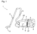
- Fig. 1 shows a vacuum cleaner 1 with a motor-blower unit 3 for generating a suction air stream 5, and arranged in a dust chamber 43 Staubabscheideech On the vacuum cleaner 1 is further a main filter 37, which is a motor protection filter, arranged in the suction air stream 5, the Staubabscheideech 7 downstream in the direction of Saugluftstroms 5 and the motor-fan unit 3 in the direction of Suction air stream 5 is upstream.
- main filter 37 which is a motor protection filter
- a rib means 9 is arranged in the suction air stream 5 of the vacuum cleaner 1, which is non-positively connected to the main filter 37 and thus to the vacuum cleaner 1, and thereby downstream of the Staubabscheideiki 7 in the direction of the suction air stream 5.
- the rib means 9 is attached to the main filter 37, and is connected upstream of the main filter 37 in the direction of the suction air stream 5.
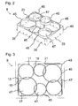
- Fig. 2 shows the rib device 9 in a perspective view.
- Fig. 3 shows the rib means 9 according to Fig. 2 in a view from above.
- the rib device 9 has six ribs 45, inter alia a first rib 11 with a first rib section 13, a second rib 17 with a second rib section 15 and a further third rib 21 with a further, third rib section 19, wherein the first 13 , the second 15 and the third 19 rib section form a circular arc, so are arcuate.
- the rib device 9 has three ribs, so that a total of six ribs 45 are arranged on the rib device 9.
- the first 11, the second 17 and the third 21 is circular, with the first 13, the second 15 and the third rib portion 19 extends over the entire rib.
- the ribs 11, 17, 19 are arranged on the rib device 9 in such a way that the first 13 and the second rib section 15 overlap twice, ie touch, and the first 13 and the third rib section 19 touch tangentially.
- the first 11, second 17 and third 21 and all remaining ribs of the rib device 9 have a constant rib height 23, wherein the constant rib height 23 of the first 11 of the constant rib height 23 of the second rib 17, and the constant rib height 23 of the first eleventh is different from the constant rib height 23 of the third rib 21.
- all the ribs 45 have a different constant rib height 23.
- the rib edges of all ribs stand out of the rib device, wherein the rib edges 25 of the ribs 45 projecting from the rib device 9 lie in at least two planes, which are not shown in the figures for reasons of illustration.
- the Staubabscheideiki 7 at the rib means 9 are prevented.
- the suction air stream 5 can flow through the rib device 9.
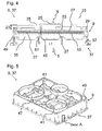
- the rib device 9 has a holding frame 49, an auxiliary frame 29 and a supplementary material 27, which contains odor-neutralizing and odor-covering substances.
- the non-positively connected with the main filter 37 rib means 9, the sub-frame 29 and the additional material 27 are in Fig. 4 in a sectional view and in Fig. 5 shown in a perspective view. For reasons of illustration, the subframe 29 and the additional material 27 are not in Fig. 5 shown.
- the fin means 9, which is a dispenser emits odor-neutralizing and odor-blanketing substances into the suction air stream 5.
- the rib device 8 can take the Saugluftstrom 5 particles and deliver odor-neutralizing and odor-masking substances in the suction air stream 5.
- the additional material 27 is held in the subframe 29, which has ribs 51 and windows 47. Attached to the subframe 29 are two air permeable fabrics 53, one cloth 53 at the top, and the other cloth 53 at the bottom of the subframe 29 extending over the windows 47 of the subframe 29.
- the additional material 27 is supported by the fabrics 53 in the sub-frame 29, whereby a particularly simple manufacturing process is made possible.
- the odor-neutralizing substances are delivered in the form of cage compounds, so-called clathrates in the suction air stream 5, the clathrates were purchased through the company "et-project” with the trade name "SinoAir®".
- This ingredient consists mainly of plant clathrates.
- the active ingredient is combined with essential essences in a gel derived from vegetable substances. As a result, the use can be realized up to one year.
- the odor-masking substances are delivered as perfume substances with the fragrance note lemon in the suction air stream 5.
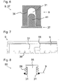
- Recesses 39 which correspond to the ribs 41 of the main filter 37 are arranged on the rib device 9.
- the corresponding with the recesses 39 of the holding frame 49 ribs 41 of the main filter 37 are not shown for purposes of illustration. However, these ribs 41 as an extension of the illustrated ribs 41 be thought. How out Fig. 6 can be seen, the recesses 37 have a greater extent than the corresponding corresponding rib 41, whereby a bypass opening 31 is formed on the rib means 9, which connects a first space 33 in front of the rib means 9 with the second space 35 after the rib means 9.
- the second space 35 is not limited to the space between rib means 9 and main filter 37, but may also extend beyond the main filter 37 in the direction of the suction air stream 5 addition.
- the rib means 9 can be plugged with the recesses 39 to the ribs 41 of the main filter 37, and is thus positively connected to at least one rib 41.
- the rib means 9 In addition to the bypass openings 31 at the recesses 39, one of which in Fig. 6 is shown, the rib means 9, a further bypass opening 31, the opening cross-section via an actuating element 55, which is a slider, is variable.
- This in Fig. 7 shown actuator 55 is to bring into a rest position and a position outside the rest position, wherein in the rest position, the bypass opening 31 is closed, and in the position outside the rest position, a connection via the bypass opening 31 between the first 33 and the second space 35 is ,
- Fig. 7 is the actuator 55 in a position out of the rest position, and is manually operable.
- the user can thus even change the opening cross-section of the bypass opening 31 to reduce the opening cross-section if necessary, for example in the occurrence of malodors, and to increase the effect of the additional material 27, for example, the neutralization of odors, as at a smaller opening cross-section a larger part of the suction air stream 5 can flow through the additional material 27.
- the holding frame 49 of the rib device 9 has sealing surfaces 57 which hermetically seal the second space 35, which is located between the rib device 9 and the main filter 37, so that the suction air flow 5 can only flow through the additional material 27 or the bypass openings 31.
- the rib means 9 is integrally made of plastic, so that the rib means 9 mechanically stronger and easier with the vacuum cleaner 1 is connectable.
- a plastic injection molding method is used, whereby the rib device 9 is simple and inexpensive to manufacture.
- the actuating element 55 has a spring, that is to say an elastically deformable element 59, and is designed such that, when a threshold value of the differential pressure is exceeded, it is between the two chambers 33, 35 Pressing is in a position out of the normal position and that it is in the rest position when it falls below the threshold value.
- the rib means 9 is placed on a main filter 37, wherein the rib means 9, the main filter 37 only partially covers.
- further bypass openings 31 are formed, through which the suction air can flow past the additional material 27 of the rib device 9.
- the rib device 9 is no longer traversed by the entire suction air, whereby the life of the rib device 9 further increases. In this case, the user no longer needs to replace the filler material 27 as frequently.
- the present invention allows to provide a vacuum cleaner with a fin device with simple constructive and inexpensive means.
- a conspicuous geometry for the user can be made possible.
- the rib means enable a support and / or safety function.
Landscapes
- Engineering & Computer Science (AREA)
- Mechanical Engineering (AREA)
- Chemical & Material Sciences (AREA)
- Chemical Kinetics & Catalysis (AREA)
- Electric Suction Cleaners (AREA)
Applications Claiming Priority (1)
| Application Number | Priority Date | Filing Date | Title |
|---|---|---|---|
| DE200910002052 DE102009002052A1 (de) | 2009-03-31 | 2009-03-31 | Staubsauger mit Rippeneinrichtung |
Publications (3)
| Publication Number | Publication Date |
|---|---|
| EP2236070A2 true EP2236070A2 (fr) | 2010-10-06 |
| EP2236070A3 EP2236070A3 (fr) | 2013-08-28 |
| EP2236070B1 EP2236070B1 (fr) | 2015-03-04 |
Family
ID=42212209
Family Applications (1)
| Application Number | Title | Priority Date | Filing Date |
|---|---|---|---|
| EP10155863.3A Not-in-force EP2236070B1 (fr) | 2009-03-31 | 2010-03-09 | Aspirateur doté d'un dispositif de nervure |
Country Status (2)
| Country | Link |
|---|---|
| EP (1) | EP2236070B1 (fr) |
| DE (1) | DE102009002052A1 (fr) |
Cited By (2)
| Publication number | Priority date | Publication date | Assignee | Title |
|---|---|---|---|---|
| EP2835087A1 (fr) | 2013-08-09 | 2015-02-11 | Eurofilters N.V. | Sac filtrant d'aspirateur avec élément d'écartement |
| CN106805843A (zh) * | 2015-10-30 | 2017-06-09 | 德国福维克控股公司 | 具有芳香元件的清洗设备 |
Families Citing this family (1)
| Publication number | Priority date | Publication date | Assignee | Title |
|---|---|---|---|---|
| DE202018101431U1 (de) * | 2018-03-14 | 2019-06-17 | Vorwerk & Co. Interholding Gmbh | Saugkanalelement für ein Saugreinigungsgerät |
Citations (1)
| Publication number | Priority date | Publication date | Assignee | Title |
|---|---|---|---|---|
| DE4317715C1 (de) | 1993-05-27 | 1994-06-09 | Siemens Ag | Filterkassette für einen Staubsauger |
Family Cites Families (3)
| Publication number | Priority date | Publication date | Assignee | Title |
|---|---|---|---|---|
| US2008067A (en) * | 1932-12-14 | 1935-07-16 | Faber Ernst | Vacuum cleaner |
| US3204395A (en) * | 1963-05-08 | 1965-09-07 | Mil An Mfg Corp | Filter cap for vacuum cleaner motor |
| DE3517329A1 (de) * | 1985-05-14 | 1986-11-20 | Licentia Patent-Verwaltungs-Gmbh, 6000 Frankfurt | Staubsauger mit einem scheibenfilter |
-
2009
- 2009-03-31 DE DE200910002052 patent/DE102009002052A1/de not_active Ceased
-
2010
- 2010-03-09 EP EP10155863.3A patent/EP2236070B1/fr not_active Not-in-force
Patent Citations (1)
| Publication number | Priority date | Publication date | Assignee | Title |
|---|---|---|---|---|
| DE4317715C1 (de) | 1993-05-27 | 1994-06-09 | Siemens Ag | Filterkassette für einen Staubsauger |
Cited By (2)
| Publication number | Priority date | Publication date | Assignee | Title |
|---|---|---|---|---|
| EP2835087A1 (fr) | 2013-08-09 | 2015-02-11 | Eurofilters N.V. | Sac filtrant d'aspirateur avec élément d'écartement |
| CN106805843A (zh) * | 2015-10-30 | 2017-06-09 | 德国福维克控股公司 | 具有芳香元件的清洗设备 |
Also Published As
| Publication number | Publication date |
|---|---|
| EP2236070A3 (fr) | 2013-08-28 |
| DE102009002052A1 (de) | 2010-10-07 |
| EP2236070B1 (fr) | 2015-03-04 |
Similar Documents
| Publication | Publication Date | Title |
|---|---|---|
| DE4240172C2 (de) | Staubsauger mit einem Staubfilterbeutel und einem Nachfilter | |
| DE3490313T1 (de) | Filter für Luftreiniger | |
| EP2236072B1 (fr) | Aspirateur doté d'un dispositif supplémentaire | |
| EP2236070B1 (fr) | Aspirateur doté d'un dispositif de nervure | |
| DE3341458C2 (de) | Staubsauger mit einem Abluftfilter | |
| EP2835089A2 (fr) | Procédé de fonctionnement d'un aspirateur pour le nettoyage d'un élément de filtre enfermé dans l'aspirateur | |
| EP1139848A1 (fr) | Filtre a poussiere destine a un aspirateur | |
| WO2005100863A1 (fr) | Dispositif d'aspiration de fumees pour systeme de preparation d'aliments | |
| EP2236068B1 (fr) | Aspirateur doté d'un dispositif supplémentaire et d'un matériau supplémentaire | |
| WO1991010392A1 (fr) | Aspirateur | |
| EP1482825A1 (fr) | Sac filtrant dote d'un element parfume | |
| DE102010001140B4 (de) | Staubsauger mit Eingreifschutzgitter | |
| EP2233053B1 (fr) | Dispositif de filtre pour un aspirateur | |
| EP2236071B1 (fr) | Appareil électroménager doté d'un dispositif supplémentaire | |
| DE202009017628U1 (de) | Staubsauger mit Eingreifschutzgitter | |
| EP2510850B1 (fr) | Agencement silencieux de filtre d'air évacué | |
| DE102010003383A1 (de) | Fettfilterelement für eine Dunstabzugshaube und eine Dunstabzugshaube | |
| DE102005016274B4 (de) | Verfahren und Vorrichtung zur Geruchsneutralisation für Räume | |
| DE202014101065U1 (de) | Schüttgutrahmen mit Ton Granulat | |
| EP2510851A2 (fr) | Dispositif de filtre et méthode du filtrage silencieux d'un flux d'air évacué | |
| DE102015103019A1 (de) | Staubaufnahmesystem mit Adsorptionsmaterial aufweisender Dämmschicht | |
| DE202015007253U1 (de) | Staubfilterbeutel | |
| WO2011080037A1 (fr) | Aspirateur pourvu d'un élément de protection des mains | |
| DE102011054288A1 (de) | Motorschutzfilterhalter und Staubsauger mit einem Motorschutzfilterhalter | |
| DE20109473U1 (de) | Luftfilter |
Legal Events
| Date | Code | Title | Description |
|---|---|---|---|
| PUAI | Public reference made under article 153(3) epc to a published international application that has entered the european phase |
Free format text: ORIGINAL CODE: 0009012 |
|
| AK | Designated contracting states |
Kind code of ref document: A2 Designated state(s): AT BE BG CH CY CZ DE DK EE ES FI FR GB GR HR HU IE IS IT LI LT LU LV MC MK MT NL NO PL PT RO SE SI SK SM TR |
|
| AX | Request for extension of the european patent |
Extension state: AL BA ME RS |
|
| PUAL | Search report despatched |
Free format text: ORIGINAL CODE: 0009013 |
|
| AK | Designated contracting states |
Kind code of ref document: A3 Designated state(s): AT BE BG CH CY CZ DE DK EE ES FI FR GB GR HR HU IE IS IT LI LT LU LV MC MK MT NL NO PL PT RO SE SI SK SM TR |
|
| AX | Request for extension of the european patent |
Extension state: AL BA ME RS |
|
| RIC1 | Information provided on ipc code assigned before grant |
Ipc: B01D 46/00 20060101ALI20130723BHEP Ipc: A47L 9/12 20060101ALI20130723BHEP Ipc: A47L 9/10 20060101AFI20130723BHEP Ipc: A47L 7/04 20060101ALI20130723BHEP Ipc: A47L 7/00 20060101ALI20130723BHEP |
|
| 17P | Request for examination filed |
Effective date: 20140228 |
|
| RBV | Designated contracting states (corrected) |
Designated state(s): AT BE BG CH CY CZ DE DK EE ES FI FR GB GR HR HU IE IS IT LI LT LU LV MC MK MT NL NO PL PT RO SE SI SK SM TR |
|
| RIC1 | Information provided on ipc code assigned before grant |
Ipc: A47L 7/04 20060101ALI20140813BHEP Ipc: B01D 46/00 20060101ALI20140813BHEP Ipc: A47L 7/00 20060101ALI20140813BHEP Ipc: A47L 9/10 20060101AFI20140813BHEP Ipc: A47L 9/12 20060101ALI20140813BHEP |
|
| GRAP | Despatch of communication of intention to grant a patent |
Free format text: ORIGINAL CODE: EPIDOSNIGR1 |
|
| INTG | Intention to grant announced |
Effective date: 20140929 |
|
| GRAS | Grant fee paid |
Free format text: ORIGINAL CODE: EPIDOSNIGR3 |
|
| GRAA | (expected) grant |
Free format text: ORIGINAL CODE: 0009210 |
|
| AK | Designated contracting states |
Kind code of ref document: B1 Designated state(s): AT BE BG CH CY CZ DE DK EE ES FI FR GB GR HR HU IE IS IT LI LT LU LV MC MK MT NL NO PL PT RO SE SI SK SM TR |
|
| REG | Reference to a national code |
Ref country code: GB Ref legal event code: FG4D Free format text: NOT ENGLISH |
|
| REG | Reference to a national code |
Ref country code: CH Ref legal event code: EP |
|
| RAP2 | Party data changed (patent owner data changed or rights of a patent transferred) |
Owner name: BSH HAUSGERAETE GMBH |
|
| REG | Reference to a national code |
Ref country code: IE Ref legal event code: FG4D Free format text: LANGUAGE OF EP DOCUMENT: GERMAN |
|
| REG | Reference to a national code |
Ref country code: AT Ref legal event code: REF Ref document number: 713070 Country of ref document: AT Kind code of ref document: T Effective date: 20150415 |
|
| REG | Reference to a national code |
Ref country code: DE Ref legal event code: R096 Ref document number: 502010009030 Country of ref document: DE Effective date: 20150416 |
|
| REG | Reference to a national code |
Ref country code: FR Ref legal event code: PLFP Year of fee payment: 6 |
|
| REG | Reference to a national code |
Ref country code: NL Ref legal event code: VDEP Effective date: 20150304 |
|
| PG25 | Lapsed in a contracting state [announced via postgrant information from national office to epo] |
Ref country code: ES Free format text: LAPSE BECAUSE OF FAILURE TO SUBMIT A TRANSLATION OF THE DESCRIPTION OR TO PAY THE FEE WITHIN THE PRESCRIBED TIME-LIMIT Effective date: 20150304 Ref country code: SE Free format text: LAPSE BECAUSE OF FAILURE TO SUBMIT A TRANSLATION OF THE DESCRIPTION OR TO PAY THE FEE WITHIN THE PRESCRIBED TIME-LIMIT Effective date: 20150304 Ref country code: FI Free format text: LAPSE BECAUSE OF FAILURE TO SUBMIT A TRANSLATION OF THE DESCRIPTION OR TO PAY THE FEE WITHIN THE PRESCRIBED TIME-LIMIT Effective date: 20150304 Ref country code: HR Free format text: LAPSE BECAUSE OF FAILURE TO SUBMIT A TRANSLATION OF THE DESCRIPTION OR TO PAY THE FEE WITHIN THE PRESCRIBED TIME-LIMIT Effective date: 20150304 Ref country code: LT Free format text: LAPSE BECAUSE OF FAILURE TO SUBMIT A TRANSLATION OF THE DESCRIPTION OR TO PAY THE FEE WITHIN THE PRESCRIBED TIME-LIMIT Effective date: 20150304 Ref country code: NO Free format text: LAPSE BECAUSE OF FAILURE TO SUBMIT A TRANSLATION OF THE DESCRIPTION OR TO PAY THE FEE WITHIN THE PRESCRIBED TIME-LIMIT Effective date: 20150604 |
|
| REG | Reference to a national code |
Ref country code: LT Ref legal event code: MG4D |
|
| PG25 | Lapsed in a contracting state [announced via postgrant information from national office to epo] |
Ref country code: LV Free format text: LAPSE BECAUSE OF FAILURE TO SUBMIT A TRANSLATION OF THE DESCRIPTION OR TO PAY THE FEE WITHIN THE PRESCRIBED TIME-LIMIT Effective date: 20150304 Ref country code: GR Free format text: LAPSE BECAUSE OF FAILURE TO SUBMIT A TRANSLATION OF THE DESCRIPTION OR TO PAY THE FEE WITHIN THE PRESCRIBED TIME-LIMIT Effective date: 20150605 |
|
| PG25 | Lapsed in a contracting state [announced via postgrant information from national office to epo] |
Ref country code: NL Free format text: LAPSE BECAUSE OF FAILURE TO SUBMIT A TRANSLATION OF THE DESCRIPTION OR TO PAY THE FEE WITHIN THE PRESCRIBED TIME-LIMIT Effective date: 20150304 |
|
| PG25 | Lapsed in a contracting state [announced via postgrant information from national office to epo] |
Ref country code: SK Free format text: LAPSE BECAUSE OF FAILURE TO SUBMIT A TRANSLATION OF THE DESCRIPTION OR TO PAY THE FEE WITHIN THE PRESCRIBED TIME-LIMIT Effective date: 20150304 Ref country code: EE Free format text: LAPSE BECAUSE OF FAILURE TO SUBMIT A TRANSLATION OF THE DESCRIPTION OR TO PAY THE FEE WITHIN THE PRESCRIBED TIME-LIMIT Effective date: 20150304 Ref country code: RO Free format text: LAPSE BECAUSE OF FAILURE TO SUBMIT A TRANSLATION OF THE DESCRIPTION OR TO PAY THE FEE WITHIN THE PRESCRIBED TIME-LIMIT Effective date: 20150304 Ref country code: CZ Free format text: LAPSE BECAUSE OF FAILURE TO SUBMIT A TRANSLATION OF THE DESCRIPTION OR TO PAY THE FEE WITHIN THE PRESCRIBED TIME-LIMIT Effective date: 20150304 Ref country code: PT Free format text: LAPSE BECAUSE OF FAILURE TO SUBMIT A TRANSLATION OF THE DESCRIPTION OR TO PAY THE FEE WITHIN THE PRESCRIBED TIME-LIMIT Effective date: 20150706 |
|
| REG | Reference to a national code |
Ref country code: CH Ref legal event code: PL |
|
| REG | Reference to a national code |
Ref country code: FR Ref legal event code: CD Owner name: BSH HAUSGERATE GMBH, DE Effective date: 20151022 |
|
| PG25 | Lapsed in a contracting state [announced via postgrant information from national office to epo] |
Ref country code: PL Free format text: LAPSE BECAUSE OF FAILURE TO SUBMIT A TRANSLATION OF THE DESCRIPTION OR TO PAY THE FEE WITHIN THE PRESCRIBED TIME-LIMIT Effective date: 20150304 Ref country code: IS Free format text: LAPSE BECAUSE OF FAILURE TO SUBMIT A TRANSLATION OF THE DESCRIPTION OR TO PAY THE FEE WITHIN THE PRESCRIBED TIME-LIMIT Effective date: 20150704 |
|
| REG | Reference to a national code |
Ref country code: DE Ref legal event code: R097 Ref document number: 502010009030 Country of ref document: DE |
|
| PG25 | Lapsed in a contracting state [announced via postgrant information from national office to epo] |
Ref country code: IT Free format text: LAPSE BECAUSE OF FAILURE TO SUBMIT A TRANSLATION OF THE DESCRIPTION OR TO PAY THE FEE WITHIN THE PRESCRIBED TIME-LIMIT Effective date: 20150304 |
|
| PLBE | No opposition filed within time limit |
Free format text: ORIGINAL CODE: 0009261 |
|
| STAA | Information on the status of an ep patent application or granted ep patent |
Free format text: STATUS: NO OPPOSITION FILED WITHIN TIME LIMIT |
|
| REG | Reference to a national code |
Ref country code: IE Ref legal event code: MM4A |
|
| PG25 | Lapsed in a contracting state [announced via postgrant information from national office to epo] |
Ref country code: MC Free format text: LAPSE BECAUSE OF FAILURE TO SUBMIT A TRANSLATION OF THE DESCRIPTION OR TO PAY THE FEE WITHIN THE PRESCRIBED TIME-LIMIT Effective date: 20150304 Ref country code: IE Free format text: LAPSE BECAUSE OF NON-PAYMENT OF DUE FEES Effective date: 20150309 Ref country code: LI Free format text: LAPSE BECAUSE OF NON-PAYMENT OF DUE FEES Effective date: 20150331 Ref country code: CH Free format text: LAPSE BECAUSE OF NON-PAYMENT OF DUE FEES Effective date: 20150331 Ref country code: DK Free format text: LAPSE BECAUSE OF FAILURE TO SUBMIT A TRANSLATION OF THE DESCRIPTION OR TO PAY THE FEE WITHIN THE PRESCRIBED TIME-LIMIT Effective date: 20150304 |
|
| 26N | No opposition filed |
Effective date: 20151207 |
|
| PG25 | Lapsed in a contracting state [announced via postgrant information from national office to epo] |
Ref country code: SI Free format text: LAPSE BECAUSE OF FAILURE TO SUBMIT A TRANSLATION OF THE DESCRIPTION OR TO PAY THE FEE WITHIN THE PRESCRIBED TIME-LIMIT Effective date: 20150304 |
|
| REG | Reference to a national code |
Ref country code: FR Ref legal event code: PLFP Year of fee payment: 7 |
|
| REG | Reference to a national code |
Ref country code: AT Ref legal event code: MM01 Ref document number: 713070 Country of ref document: AT Kind code of ref document: T Effective date: 20150309 |
|
| PG25 | Lapsed in a contracting state [announced via postgrant information from national office to epo] |
Ref country code: AT Free format text: LAPSE BECAUSE OF NON-PAYMENT OF DUE FEES Effective date: 20150309 |
|
| PG25 | Lapsed in a contracting state [announced via postgrant information from national office to epo] |
Ref country code: MT Free format text: LAPSE BECAUSE OF FAILURE TO SUBMIT A TRANSLATION OF THE DESCRIPTION OR TO PAY THE FEE WITHIN THE PRESCRIBED TIME-LIMIT Effective date: 20150304 |
|
| REG | Reference to a national code |
Ref country code: FR Ref legal event code: PLFP Year of fee payment: 8 |
|
| PG25 | Lapsed in a contracting state [announced via postgrant information from national office to epo] |
Ref country code: BG Free format text: LAPSE BECAUSE OF FAILURE TO SUBMIT A TRANSLATION OF THE DESCRIPTION OR TO PAY THE FEE WITHIN THE PRESCRIBED TIME-LIMIT Effective date: 20150304 Ref country code: SM Free format text: LAPSE BECAUSE OF FAILURE TO SUBMIT A TRANSLATION OF THE DESCRIPTION OR TO PAY THE FEE WITHIN THE PRESCRIBED TIME-LIMIT Effective date: 20150304 Ref country code: HU Free format text: LAPSE BECAUSE OF FAILURE TO SUBMIT A TRANSLATION OF THE DESCRIPTION OR TO PAY THE FEE WITHIN THE PRESCRIBED TIME-LIMIT; INVALID AB INITIO Effective date: 20100309 |
|
| PG25 | Lapsed in a contracting state [announced via postgrant information from national office to epo] |
Ref country code: CY Free format text: LAPSE BECAUSE OF FAILURE TO SUBMIT A TRANSLATION OF THE DESCRIPTION OR TO PAY THE FEE WITHIN THE PRESCRIBED TIME-LIMIT Effective date: 20150304 |
|
| PG25 | Lapsed in a contracting state [announced via postgrant information from national office to epo] |
Ref country code: BE Free format text: LAPSE BECAUSE OF NON-PAYMENT OF DUE FEES Effective date: 20150331 |
|
| PG25 | Lapsed in a contracting state [announced via postgrant information from national office to epo] |
Ref country code: TR Free format text: LAPSE BECAUSE OF FAILURE TO SUBMIT A TRANSLATION OF THE DESCRIPTION OR TO PAY THE FEE WITHIN THE PRESCRIBED TIME-LIMIT Effective date: 20150304 |
|
| PG25 | Lapsed in a contracting state [announced via postgrant information from national office to epo] |
Ref country code: LU Free format text: LAPSE BECAUSE OF NON-PAYMENT OF DUE FEES Effective date: 20150309 |
|
| REG | Reference to a national code |
Ref country code: FR Ref legal event code: PLFP Year of fee payment: 9 |
|
| PG25 | Lapsed in a contracting state [announced via postgrant information from national office to epo] |
Ref country code: MK Free format text: LAPSE BECAUSE OF FAILURE TO SUBMIT A TRANSLATION OF THE DESCRIPTION OR TO PAY THE FEE WITHIN THE PRESCRIBED TIME-LIMIT Effective date: 20150304 |
|
| PGFP | Annual fee paid to national office [announced via postgrant information from national office to epo] |
Ref country code: FR Payment date: 20190326 Year of fee payment: 10 Ref country code: GB Payment date: 20190325 Year of fee payment: 10 |
|
| PG25 | Lapsed in a contracting state [announced via postgrant information from national office to epo] |
Ref country code: FR Free format text: LAPSE BECAUSE OF NON-PAYMENT OF DUE FEES Effective date: 20200331 |
|
| GBPC | Gb: european patent ceased through non-payment of renewal fee |
Effective date: 20200309 |
|
| PG25 | Lapsed in a contracting state [announced via postgrant information from national office to epo] |
Ref country code: GB Free format text: LAPSE BECAUSE OF NON-PAYMENT OF DUE FEES Effective date: 20200309 |
|
| PGFP | Annual fee paid to national office [announced via postgrant information from national office to epo] |
Ref country code: DE Payment date: 20230331 Year of fee payment: 14 |
|
| P01 | Opt-out of the competence of the unified patent court (upc) registered |
Effective date: 20230504 |
|
| REG | Reference to a national code |
Ref country code: DE Ref legal event code: R119 Ref document number: 502010009030 Country of ref document: DE |
|
| PG25 | Lapsed in a contracting state [announced via postgrant information from national office to epo] |
Ref country code: DE Free format text: LAPSE BECAUSE OF NON-PAYMENT OF DUE FEES Effective date: 20241001 |
|
| PG25 | Lapsed in a contracting state [announced via postgrant information from national office to epo] |
Ref country code: DE Free format text: LAPSE BECAUSE OF NON-PAYMENT OF DUE FEES Effective date: 20241001 |