EP2234477B1 - Milchsammelnde komponenten mit schliessbaren kammern - Google Patents
Milchsammelnde komponenten mit schliessbaren kammern Download PDFInfo
- Publication number
- EP2234477B1 EP2234477B1 EP08862728.6A EP08862728A EP2234477B1 EP 2234477 B1 EP2234477 B1 EP 2234477B1 EP 08862728 A EP08862728 A EP 08862728A EP 2234477 B1 EP2234477 B1 EP 2234477B1
- Authority
- EP
- European Patent Office
- Prior art keywords
- closing body
- trough
- collecting piece
- milk collecting
- milk
- Prior art date
- Legal status (The legal status is an assumption and is not a legal conclusion. Google has not performed a legal analysis and makes no representation as to the accuracy of the status listed.)
- Active
Links
- 239000008267 milk Substances 0.000 title claims description 101
- 210000004080 milk Anatomy 0.000 title claims description 101
- 235000013336 milk Nutrition 0.000 title claims description 101
- 239000012530 fluid Substances 0.000 claims description 5
- 239000000463 material Substances 0.000 claims description 3
- 238000004891 communication Methods 0.000 claims description 2
- 210000002445 nipple Anatomy 0.000 description 30
- 238000007789 sealing Methods 0.000 description 14
- 229920001971 elastomer Polymers 0.000 description 10
- 239000005060 rubber Substances 0.000 description 10
- 238000000034 method Methods 0.000 description 9
- 241001465754 Metazoa Species 0.000 description 6
- 239000000203 mixture Substances 0.000 description 4
- 241000283690 Bos taurus Species 0.000 description 3
- 229910000831 Steel Inorganic materials 0.000 description 3
- 230000001070 adhesive effect Effects 0.000 description 3
- 239000010959 steel Substances 0.000 description 3
- 230000007423 decrease Effects 0.000 description 2
- 230000001419 dependent effect Effects 0.000 description 2
- 230000000694 effects Effects 0.000 description 2
- 239000007788 liquid Substances 0.000 description 2
- 241000283707 Capra Species 0.000 description 1
- 241001494479 Pecora Species 0.000 description 1
- 239000000853 adhesive Substances 0.000 description 1
- 210000000481 breast Anatomy 0.000 description 1
- 210000000078 claw Anatomy 0.000 description 1
- 238000013016 damping Methods 0.000 description 1
- 238000011161 development Methods 0.000 description 1
- 230000018109 developmental process Effects 0.000 description 1
- 238000003032 molecular docking Methods 0.000 description 1
- 230000035484 reaction time Effects 0.000 description 1
- 230000002123 temporal effect Effects 0.000 description 1
Images


Classifications
-
- A—HUMAN NECESSITIES
- A01—AGRICULTURE; FORESTRY; ANIMAL HUSBANDRY; HUNTING; TRAPPING; FISHING
- A01J—MANUFACTURE OF DAIRY PRODUCTS
- A01J5/00—Milking machines or devices
- A01J5/04—Milking machines or devices with pneumatic manipulation of teats
- A01J5/041—Milk claw
Definitions
- the subject-matter of the invention relates to a milk collecting piece comprising a housing upper part with at least two intake nozzles and a housing lower part with at least two chambers which are each flow-connected to an outtake nozzle via an outlet.
- a milking implement comprises a milk collecting piece which is connected to a teat cup via a respective short milking hose.
- the teat cup comprises a sleeve in which a teat rubber is arranged.
- the teat rubber is connected to the short milking hose. It is known that the teat rubber and the short milking hose are used in one piece as what is known as a monoblock.
- the short milking hose is connected to an intake nozzle.
- the milk flowing into the milk collecting piece through the milking hoses is conveyed away from the milk collecting piece via an outtake nozzle.
- the milk collecting piece is connected to a milk conveying line.
- a long milking hose is used for connecting.
- milk collecting pieces For the milking of sheep and goats, milk collecting pieces are known having two intake nozzles. For the milking of cows, milk collecting pieces are known having four intake nozzles. The number of intake nozzles corresponds to the number of teats of the milk-providing animal.
- Document US 4,434,744 discloses a milk collecting piece having a housing.
- the housing is formed by a housing upper part and a housing lower part. At least two intake nozzles are provided. At least two chambers, which are each flow-connected to an outtake nozzle via an outlet, are provided within the housing.
- Document DE 10 2005 017 094 A1 discloses a further embodiment of a milk collecting piece.
- This document describes a milk collecting piece with a housing in which four chambers are provided. The chambers are connected to intake nozzles. The milk entering the chambers issues from the milk collecting piece via an outtake nozzle.
- WO 98/04118 A1 discloses a milk collecting piece comprising a casing defining an inner space.
- inlet members which each, via a respective short milk line, are connected to a respective teat cup. Milk extracted from teats is led via the inlet members into the inner space of the connecting piece and from there it is transported via an outlet pipe and a milk line to a milk collecting container.
- a valve body provided within the inner space.
- This valve body is provided with a connecting member which extends through the wall of the inner space of the claw.
- the connecting member is connected with an operating member.
- There a docking means which operate with operating member in such a way that the valve body can be located in an open position.
- the situation can occur that a milking cup falls away from the teat or is detached by the animal to be milked. If the milking cup falls away from the teat, then air flows through the milking cup and the short milking hose into the milk collecting piece. With the air, dirt can enter the milk collecting piece and ultimately the milk collecting container.
- the intake nozzles are configured in such a way that the milking hose kinks at the free end of the intake nozzle, so that the supply of air is interrupted.
- the valve function of the outtake nozzle/milking hose pairing is not satisfactory. This problem has already become known.
- US-A-4,483,272 or CH-A5-667 973 provides in the milking cup a valve which can be used to prevent milk from issuing from the milking cup.
- the valve is formed by a valve body which enters into abutment against the valve seat as a result of reduced pressure or under the action of gravitational force.
- the present invention is based on the objective of developing the known milk collecting piece in such a way that the operation of the milk collecting piece is improved still further.
- the milk collecting piece according to the invention has a housing.
- the housing is formed by a housing upper part and a housing lower part.
- the milk collecting piece has at least two intake nozzles. Each intake nozzle opens into a respective chamber which is formed in the housing. Each chamber is in fluid communication with an outtake nozzle via an outlet.
- at least one chamber has a bottom in which a trough is formed.
- a closing body is provided and is located, in a first position in the trough, below the outlet and, in a second position, above the through.
- the closing body Once the closing body has assumed the first position, then the outlet from the chamber is cleared, so that the milk flowing into the chamber through the intake nozzle can enter the outtake nozzle via the outlet.
- said closing body In the second position which the closing body can assume, said closing body is located before the outlet, in such a way that said outlet is substantially sealed off, so that the flow connection between the chamber and the outtake nozzle is substantially interrupted.
- the milking cups are attached to the teats.
- the teat rubbers of the milking cups cover the teat as completely as possible.
- milk or a milk/air mixture flows into the milk collecting piece.
- the milk or the milk/air mixture leaves the chamber through the outlet and enters the outtake nozzle.
- the closing body is located in the trough. In this case, milk or the milk/air mixture flows over the closing body.
- a significant advantage of the milk collecting piece according to the invention may also be seen in the fact that a closing function is preserved even in the event of disadvantageous situations or positions of the milk collecting piece; this is not the case in the collecting pieces according to the prior art.
- the closing body is preferably embodied in such a way as to be substantially spherical. This has inter alia the advantage that the closing body does not have to be oriented in a predefined manner.
- the closing body have a surface consisting of at least one food-compatible material.
- the closing body is made of high-grade steel, preferably stainless high-grade steel.
- the closing body have a mass between 5 g and 10 g, preferably 7 g. It has been found that a closing body having such a mass on the one hand does not float in the milk and on the other hand is sufficiently light to be drawn up to the outlet by suction.
- a gap is provided between the closing body and the casing of the trough.
- milk flows into the gap during the milking process, so that a liquid film is formed between the closing body and the trough surface.
- the surface tension of this liquid film has an adhesive effect on the closing body.
- the resulting adhesion force counteracts a suction force, acting on the closing body as a result of the flow, on the surface part of the closing body, which is positioned in the flow, thus allowing a relatively high milk flow without the closing body being removed from the trough by suction during the milk flow and drawn before the outlet.
- the gap has a width between 0.1 mm and 1 mm, in particular 0.25 mm.
- the gap is embodied in a substantially annular manner.
- an advantageous configuration of the milk collecting piece proposes that a means be provided by which a centring of the closing body in the trough is brought about.
- the at least one means can have structures which are formed on the casing. It is particularly advantageous if the structures are at least three webs. If webs are provided, then the webs are preferably, viewed in the circumferential direction of the trough, arranged equidistantly to one another.
- the webs or the means are embodied in such a way that the closing body can move in the longitudinal direction of the trough.
- a further advantageous configuration of the milk collecting piece according to the invention proposes that at least one channel be provided and connect the trough to the chamber. As a result of the channel, the conveyance of milk out of the trough is increased. This decreases the closing time, as a result of which the amount of air flowing through the milk collecting piece can also advantageously be reduced
- the trough have at least one wall which is elastically deformable.
- the elastically deformable trough causes the sealing body to be secured under the pressure differential. If the pressure differential is reduced, the trough is to a certain extent demoulded, as a result of which the closing body is released. The closing body can pass to the outlet.
- the gap is preferably selected in such a way that the closing body falls away from the outlet within less than 5 sec.
- the dimensions of the gap are such that the closing body falls from the outlet within less than 1 sec.
- the attaching process or the build-up of the vacuum in the milking cup or in the chamber can be accelerated still further as a result of the fact that at least one resilient element, which, in the second position of the closing body, exerts on said body a force directed substantially away from the outlet, is provided adjacent to the outlet.
- FIGS 1 and 2 are schematic views of an exemplary embodiment of a milk collecting piece according to the invention.
- the milk collecting piece has a housing 1.
- the housing 1 is embodied in two parts. It has a housing upper part 2 and a housing lower part 3.
- the housing upper part 2 and the housing lower part 3 are joined together via connecting means (not shown). Both the housing upper part 2 and the housing lower part 3 have sealing surfaces, thus allowing the housing parts 2, 3 to be joined together in an airtight manner.
- the housing upper part 2 is connected to intake nozzles 4, 5.
- the intake nozzles 4, 5 have mouths into which corresponding chambers of the milk collecting piece open.
- the milk collecting piece has four intake nozzles.
- a milking hose (not shown) is connected to each of the intake nozzles.
- the intake nozzles can be formed on the housing upper part 2. It is also possible for the intake nozzles to be able to be formed on the housing lower part.
- the term ''an intake nozzle'' can also refer to an intake opening. If an intake opening is provided, an end region of a milking hose can be introduced therein. The end region can have an annular groove into which an edge region of the intake opening protrudes.
- the housing lower part has four chambers 8, 9, 18 and 19, as may be seen from the view according to Figure 2 .
- the chambers 8, 9, 18 and 19 are each connected to a milking cup via an intake nozzle which is connected to a milking hose, so that the milk output of one udder quarter enters one chamber.
- Each chamber 8, 9, 18 and 19 has a respective bottom 12, 13, 20 and 21.
- a trough 14 is formed in the bottom 12 of the chamber 8.
- Corresponding troughs 15, 22 and 23 are provided in the chambers 9, 18 and 19.
- each chamber Adjacent to the troughs, each chamber has an outlet 10, 11, 16 and 17, so that the milked milk can flow out of the chambers into a collecting chamber 24 through the outlets.
- the milk leaves the collecting chamber 24 through an outtake nozzle 25 which is connected to a long milking hose 26.
- a respective closing body 27 is located in each trough.
- the closing body assumes in the trough a first position. In a second position, the closing body is located before the outlet of the chamber in question.
- FIG. 3 is a section and a side view of a chamber 8. Two positions of the closing body 27 are illustrated in broken lines.
- the closing body 27 is located in one position in the trough and in the other above the trough.
- the closing body can assume this upper position if, for example, the milk collecting piece is rotated.
- the closing body 27 is embodied in a substantially spherical manner. Particularly preferred is in this case a closing body, the surface of which consists at least partly of a food-compatible material. Particularly preferred is the embodiment of a closing body in the form of a steel ball having a weight of approx. 7 g.
- the trough 14 is adapted to the contour of the closing body 27.
- the ratio of the depth of the trough to the diameter of the closing body is between 0.4 and 0.9, preferably 0.7. In the case of the preferred configuration, the overhang of the closing body out of the trough is approx. 30 % of the ball diameter.
- the outlet 10 has a substantially circular cross section.
- the diameter of the outlet is smaller than the diameter of the spherical closing body 27.
- the outlet 10 has a sealing surface 28. In the second position, the closing body 27 rests against the sealing surface 28 of the outlet 10, so that the outlet 10 is closed.
- Figure 3 shows a modified chamber 8.
- a wall 29, which restricts the movement of the closing body 27, is provided in the chamber 8.
- the wall 29 has preferably a wedge-shaped/circular cross section.
- the wall 29 extends in the direction of the bottom 12 and ends before said bottom so as to form a gap 30.
- the gap 30 has preferably a height which is somewhat less than the diameter of the closing body 27, so that the closing body is movable substantially within the space delimited by the wall 29 and also the side wall of the chamber. This has the advantage that the closing body can enter the trough 14 at all times.
- Two positions of the closing body 27 are illustrated in broken lines. In the first position, the closing body is located in the trough 14. In the second position (illustrated in broken lines), the closing body passes upward beyond the outlet 10, the movement of the closing body being delimited by the wall 29.
- the sealing surface 28 has preferably at least one conduit 31. Targeted leakage between the chamber 8 and the collecting chamber 24 is generated through the conduit 31. In the event of reduced pressure in the collecting chamber and in the illustrated position of the closing body 27 before the outlet 10, an airflow of low definition flows permanently without substantially reducing the pressure in the collecting chamber 24.
- Figure 4 is a schematic section of the chamber 8 of the milk collecting piece connected to a short milking hose 32 and a milking cup 33.
- the milking hose 32 is connected to the chamber 8 via an intake nozzle 4.
- the view according to Figure 4 shows the closing body 27 in a first position in which the closing body 27 is located in the trough 14.
- a teat is located within the milking cup.
- the teat is preferably arranged in the teat rubber in such a way that between the teat and teat rubber no air or only a small air inlet is possible.
- the closing body 27 is located in the trough 14, so that the outlet 10 is cleared.
- the view of Figure 4 reveals that the bulk of the closing body 27 is located in the trough 14.
- Figures 6 and 7 illustrate a still further exemplary embodiment of a milk collecting piece according to the invention.
- the embodiment illustrated in Figure 6 corresponds substantially to the configuration of the chamber 8.
- Figure 6 and Figure 7 show a trough 14 having a substantially cylindrical portion.
- a gap 36 is formed between the closing body 27 and the casing 35 of the cylindrical portion 34.
- the views in Figures 6 and 7 reveal that a means 39 is provided.
- the means 39 is in the form of webs extending in the longitudinal direction of the trough.
- the view according to Figure 6 shows that the webs are formed in the substantially cylindrical portion 34.
- the view in Figure 7 shows the provision of three webs arranged substantially equidistantly to one another.
- the means 39 can be formed also by structures, for example knob-shaped projections.
- the means centre the closing body 27 in the trough 14. As a result, the gap 36 is kept substantially constant.
- the means 39 are directed radially inward, the means having a radially inwardly directed extension such as to allow movement of the closing body in the longitudinal direction of the trough.
- the surface tension of the milk film in the gap 36 has an adhesive effect relative to a suction force on the surface part of the closing body 27, which is positioned in the milk flow, and thus allows a higher milk flow, without the closing body 27 being pressed during a milking process against the sealing surface 28 of the outlet 10.
- the gap 36 between the closing body 27 and the casing 35 of the trough 14 allows damping of speed peaks. If a fluid flows over the closing body 27, then a certain suction force acts on said body. The suction force increases in tandem with the flow speed of the fluid. The suction force counteracts the weight of the closing body 27. If the suction force acts on the closing body 27, then a reduced pressure, which draws the closing body downward, is formed below the closing body. This reduced pressure is also broken down in that fluid is added to the gap. Once the gap is completely covered by milk, only milk can continue to run. This allows the speed peaks to be broken down without the closing body being drawn completely out of the trough by suction, so that speed peaks of the milk have substantially no influence on the closing behaviour of the closing body.
- the milking cup For attaching the milking cup to the teat of an animal, the milking cup is, insofar as it is not attached automatically by means of a milking robot, attached to the animal by hand.
- the closing body 27 is located before the outlet 10 or on the sealing surface 28.
- the amount of air flowing through the conduit 31 is relatively low compared to the amount of air which would have to be removed by suction from the chamber 8, the milking hose 32 and the teat cup 33 in order to break down a certain pressure differential between the chamber 8 and the collecting chamber 24, so that the closing body 27 enters the trough 14.
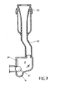
- a resilient element 38 against which the closing body 27 rests, as it may also be seen from Figure 9 , is provided to speed this up.
- the resilient element 38 exerts a force on the closing body 27 which is directed in opposition to the outlet 10. As a result, the closing body 27 enters the trough 14 at an earlier point in time.
Landscapes
- Life Sciences & Earth Sciences (AREA)
- Animal Husbandry (AREA)
- Environmental Sciences (AREA)
- External Artificial Organs (AREA)
Claims (13)
- Milchsammelstück, umfassend ein Gehäuse (1) mit einem oberen Gehäuseteil (2) und einem unteren Gehäuseteil (3), wenigstens zwei Einlassstutzen (4, 5) mit wenigstens zwei Kammern (8, 9, 18, 19), welche im Gehäuse (1) angeordnet sind und wobei sich jede dieser Kammern in Fluidverbindung mit einem Auslassstutzen (25) über einen Auslass (10, 11, 16, 17) befindet, dadurch gekennzeichnet, dass wenigstens eine Kammer (8, 9, 18, 19) einen Boden (12, 13, 20, 21) aufweist, in welchem eine Mulde (14, 15, 22, 23) ausgebildet ist, dass ein Verschlusskörper (27) vorgesehen ist und in einer ersten Position im Mulde (14, 15, 22, 23) unterhalb des Auslasses und in einer zweiten Position oberhalb der Mulde (14, 15, 22, 23) angeordnet ist und ein Spalt (36) in der ersten Position zwischen dem Verschlusskörper (27) und dem Gehäuse (35) einer Mulde (14, 15, 22, 23) ausgebildet ist und wobei die Mulde ein Abschnitt (34) ist, welcher, wenn in der Längsrichtung der Mulde betrachtet, im Wesentlichen kreisrund im Querschnitt ist, vorzugsweise als ein konstanter Querschnitt, wobei die Mulde mit einem Kanal (37) bereitgestellt ist.
- Milchsammelstück nach Anspruch 1, dadurch gekennzeichnet, dass der Verschlusskörper (27) in einer im Wesentlichen kugeligen Weise umgesetzt ist.
- Milchsammelstück nach Anspruch 1 oder 2, dadurch gekennzeichnet, dass der Verschlusskörper (27) eine Oberfläche aufweist, welche wenigstens ein lebensmittelechtes Material umfasst.
- Milchsammelstück nach Anspruch 1, 2 oder 3, dadurch gekennzeichnet, dass der Verschlusskörper (27) eine Masse zwischen 5 g und 10 g aufweist, vorzugsweise 7 g.
- Milchsammelstück nach einem der Ansprüche 1 bis 4, dadurch gekennzeichnet, dass der Spalt (36) eine Breite zwischen 0,1 mm und 1 mm aufweist, insbesondere 0,25 mm.
- Milchsammelstück nach einem der Ansprüche 1 bis 5, dadurch gekennzeichnet, dass die Mulde (14, 15, 22, 23) einen im Wesentlichen ebenen Boden aufweist.
- Milchsammelstück nach wenigstens einem der vorangehenden Ansprüche 1 bis 6, dadurch gekennzeichnet, dass ein Mittel (39) vorgesehen ist, durch welches ein Zentrieren des Verschlusskörpers (27) in der Mulde (14, 15, 22, 23) bewirkt wird.
- Milchsammelstück nach Anspruch 7, dadurch gekennzeichnet, dass das Mittel (39) Strukturen auf dem Gehäuse (35) der Mulde (14, 15, 22, 25) umfasst.
- Milchsammelstück nach Anspruch 8, dadurch gekennzeichnet, dass die Strukturen durch wenigstens drei Netze ausgebildet sind.
- Milchsammelstück nach Anspruch 9, dadurch gekennzeichnet, dass die Netze zueinander den gleichen Abstand aufweisen, wenn in der Umfangsrichtung der Mulde betrachtet.
- Milchsammelstück nach wenigstens einem der vorangehenden Ansprüche 1 bis 10, dadurch gekennzeichnet, dass wenigstens ein Kanal (37) bereitgestellt ist und die Mulde (14, 15, 22, 23) mit der Kammer (8, 9, 18, 19) verbindet.
- Milchsammelstück nach wenigstens einem der vorangehenden Ansprüche 1 bis 11, dadurch gekennzeichnet, dass die Mulde (14, 15, 22, 23) wenigstens eine Wand aufweist, welche elastisch verformbar ist.
- Milchsammelstück nach wenigstens einem der vorangehenden Ansprüche 1 bis 12, dadurch gekennzeichnet, dass wenigstens ein elastisches Element (38), welches in der zweiten Position des Verschlusskörpers (27) auf den Körper eine Kraft ausübt, die im Wesentlichen weg vom Auslass gerichtet ist, benachbart dem Auslass (10, 11, 16, 17) bereitgestellt ist.
Priority Applications (1)
| Application Number | Priority Date | Filing Date | Title |
|---|---|---|---|
| PL08862728T PL2234477T3 (pl) | 2007-12-19 | 2008-12-18 | Kolektory udojowe z zamykanymi komorami |
Applications Claiming Priority (2)
| Application Number | Priority Date | Filing Date | Title |
|---|---|---|---|
| DE102007061275 | 2007-12-19 | ||
| PCT/EP2008/067939 WO2009077607A1 (en) | 2007-12-19 | 2008-12-18 | Milk collecting pieces with closable chambers |
Publications (2)
| Publication Number | Publication Date |
|---|---|
| EP2234477A1 EP2234477A1 (de) | 2010-10-06 |
| EP2234477B1 true EP2234477B1 (de) | 2013-04-10 |
Family
ID=40473608
Family Applications (1)
| Application Number | Title | Priority Date | Filing Date |
|---|---|---|---|
| EP08862728.6A Active EP2234477B1 (de) | 2007-12-19 | 2008-12-18 | Milchsammelnde komponenten mit schliessbaren kammern |
Country Status (10)
| Country | Link |
|---|---|
| US (1) | US8438992B2 (de) |
| EP (1) | EP2234477B1 (de) |
| CN (1) | CN101932230B (de) |
| BR (1) | BRPI0821028B1 (de) |
| DE (1) | DE102008063715B4 (de) |
| ES (1) | ES2421181T3 (de) |
| NZ (1) | NZ585871A (de) |
| PL (1) | PL2234477T3 (de) |
| RU (1) | RU2465768C2 (de) |
| WO (1) | WO2009077607A1 (de) |
Families Citing this family (21)
| Publication number | Priority date | Publication date | Assignee | Title |
|---|---|---|---|---|
| US8117989B2 (en) | 2008-06-27 | 2012-02-21 | Gea Farm Technologies, Inc. | Milk tube dome with flow controller |
| US10874084B2 (en) | 2004-06-12 | 2020-12-29 | Gea Farm Technologies, Inc. | Safety valve for a dairy system component |
| US8025029B2 (en) | 2004-06-12 | 2011-09-27 | Gea Farm Technologies, Inc. | Automatic dairy animal milker unit backflusher and teat dip applicator system and method |
| US8342125B2 (en) | 2004-06-12 | 2013-01-01 | Gea Farm Technologies, Inc. | Safety valve for an automatic dairy animal milker unit backflusher and teat dip applicator |
| US8033247B2 (en) | 2004-06-12 | 2011-10-11 | Gea Farm Technologies, Inc. | Automatic dairy animal milker unit backflusher and teat dip applicator system and method |
| EP2355652B2 (de) | 2008-11-10 | 2021-03-17 | GEA Farm Technologies GmbH | Verfahren und Vorrichtung zum automatischen inkontaktbringen eines Fluids mit den Zitzen eines Tieres |
| NZ598470A (en) | 2009-09-04 | 2013-07-26 | Gea Farm Technologies Inc | A milker unit backflushing system for cleaning a dairy animal milker unit after milking, wherein the backflushing system comprises a safety valve located downstream of the milker unit which moves between a milking position and a backflushing position |
| US11723341B2 (en) | 2009-09-04 | 2023-08-15 | Gea Farm Technologies, Inc. | Safety valve for an automated milker unit backflushing and teat dip applicator system |
| US8770146B2 (en) | 2009-09-04 | 2014-07-08 | Gea Farm Technologies, Inc. | Methods and apparatus for applying teat dip to a dairy animal |
| US20120097107A1 (en) | 2010-02-22 | 2012-04-26 | Gea Farm Technologies, Inc. | Dairy animal milking preparation system and methods |
| US8925483B2 (en) | 2010-02-22 | 2015-01-06 | Gea Farm Technologies, Inc. | Dairy harvesting facility with milk line protection system and methods |
| CA2824893C (en) * | 2011-01-21 | 2020-02-11 | Pharming Intellectual Property Bv | Milking device |
| WO2012126502A1 (de) | 2011-03-18 | 2012-09-27 | Gea Farm Technologies Gmbh | Melkzeug und melkstand mit einem solchen melkzeug |
| ITMI20111414A1 (it) * | 2011-07-28 | 2013-01-29 | Milkline Srl | Dispositivo di afferraggio per un gruppo di mungitura |
| DE102012110501A1 (de) | 2012-03-14 | 2013-09-19 | Gea Farm Technologies Gmbh | Platzteiler einer Melkstandanordnung und Melkstandanordnung |
| CA2890793C (en) * | 2012-12-19 | 2020-12-22 | Delaval Holding Ab | A claw for a milking machine |
| DE102013114595A1 (de) | 2013-12-20 | 2015-06-25 | Gea Farm Technologies Gmbh | Sicherheitsventil |
| US9526224B2 (en) | 2013-12-20 | 2016-12-27 | Gea Farm Technologies Gmbh | Safety valve device |
| DE102016108300A1 (de) | 2016-05-04 | 2017-11-09 | Gea Farm Technologies Gmbh | Sicherheitsventil |
| US11206805B2 (en) | 2017-11-03 | 2021-12-28 | Gea Farm Technologies Gmbh | Automated milking system safety valve arrangement |
| DE102022117866A1 (de) * | 2022-07-18 | 2024-01-18 | Gea Farm Technologies Gmbh | Vorrichtung und Verfahren zur Kontrolle eines Melkprozesses |
Family Cites Families (21)
| Publication number | Priority date | Publication date | Assignee | Title |
|---|---|---|---|---|
| DE1299165B (de) * | 1966-06-06 | 1969-07-10 | Maier Jakob | Melkbecher fuer Melkmaschinen |
| DK119141B (da) | 1969-01-23 | 1970-11-16 | Christensen & Co As S A | Malkemaskinegrenrør. |
| US3696790A (en) * | 1970-01-08 | 1972-10-10 | Zero Manufacturing Co | Teat cup assembly |
| GB2057845B (en) * | 1979-09-11 | 1983-01-19 | Nat Res Dev | Multi-valve clawpiece |
| SE8201338L (sv) * | 1982-03-04 | 1983-09-05 | Alfa Laval Ab | Spenkopp for mjolkningsmaskin |
| US4434744A (en) * | 1982-04-19 | 1984-03-06 | Ahi Operations Limited | Methods of and/or apparatus for milking animals |
| CH667973A5 (en) | 1984-07-04 | 1988-11-30 | Fritz Happel | Valve for milking machine - connects milk receptacle to or shuts off from source of vacuum |
| GB2182534B (en) * | 1985-11-12 | 1989-10-04 | Ambic Equip Ltd | Improvements in or relating to automatic milking apparatus and methods |
| GB2191076A (en) * | 1986-06-02 | 1987-12-09 | Thomas Leslie Seaborne | Milking machine claw |
| NL8700249A (nl) * | 1987-02-02 | 1988-09-01 | Multinorm Bv | Werkwijze voor het reinigen van een tepel van een vrouwelijk dier, melkwerkwijze en beker ten gebruike bij bovengenoemde werkwijzen. |
| US4807566A (en) * | 1987-10-05 | 1989-02-28 | Alfa-Laval, Inc. | Milk claw |
| SE9602876D0 (sv) | 1996-07-26 | 1996-07-26 | Tetra Laval Holdings & Finance | Spenkoppscentral |
| AU4658099A (en) * | 1998-06-22 | 2000-01-10 | Rieberjo B.V. | Milking device provided with cleansing means |
| SE515686C2 (sv) * | 1999-10-08 | 2001-09-24 | Delaval Holding Ab | Ventil, spenkoppscentral och mjölksystem |
| DE10132132A1 (de) | 2001-07-03 | 2003-01-16 | Jun Jakob Maier | Milchsammeleinheit |
| CN2580753Y (zh) * | 2002-09-20 | 2003-10-22 | 李明永 | 挤乳器 |
| IL163585A (en) * | 2004-08-17 | 2011-11-30 | P & P Milker Ltd | Milking cup liner |
| SE527747C2 (sv) * | 2004-09-14 | 2006-05-30 | Delaval Holding Ab | Spenkopp och spenkoppsdel |
| DE102005017094A1 (de) | 2005-04-13 | 2006-10-19 | Werner Happel | Milchsammelstück |
| US20070272160A1 (en) * | 2006-05-10 | 2007-11-29 | Michael Berentzen | Modified milk-collecting component |
| RU61088U1 (ru) * | 2006-07-31 | 2007-02-27 | Станислав Владимирович Дорофеев | Коллектор доильного аппарата |
-
2008
- 2008-12-18 WO PCT/EP2008/067939 patent/WO2009077607A1/en active Application Filing
- 2008-12-18 EP EP08862728.6A patent/EP2234477B1/de active Active
- 2008-12-18 CN CN200880121804XA patent/CN101932230B/zh active Active
- 2008-12-18 NZ NZ585871A patent/NZ585871A/en not_active IP Right Cessation
- 2008-12-18 ES ES08862728T patent/ES2421181T3/es active Active
- 2008-12-18 RU RU2010129273/13A patent/RU2465768C2/ru active
- 2008-12-18 PL PL08862728T patent/PL2234477T3/pl unknown
- 2008-12-18 US US12/734,860 patent/US8438992B2/en active Active
- 2008-12-18 BR BRPI0821028-4A patent/BRPI0821028B1/pt not_active IP Right Cessation
- 2008-12-19 DE DE102008063715.7A patent/DE102008063715B4/de active Active
Also Published As
| Publication number | Publication date |
|---|---|
| DE102008063715A1 (de) | 2009-07-09 |
| NZ585871A (en) | 2011-12-22 |
| RU2465768C2 (ru) | 2012-11-10 |
| US8438992B2 (en) | 2013-05-14 |
| BRPI0821028B1 (pt) | 2017-12-26 |
| CN101932230B (zh) | 2013-04-17 |
| US20110185974A1 (en) | 2011-08-04 |
| WO2009077607A1 (en) | 2009-06-25 |
| ES2421181T3 (es) | 2013-08-29 |
| RU2010129273A (ru) | 2012-01-27 |
| BRPI0821028A2 (pt) | 2015-02-18 |
| EP2234477A1 (de) | 2010-10-06 |
| DE102008063715B4 (de) | 2021-05-20 |
| CN101932230A (zh) | 2010-12-29 |
| PL2234477T3 (pl) | 2013-09-30 |
Similar Documents
| Publication | Publication Date | Title |
|---|---|---|
| EP2234477B1 (de) | Milchsammelnde komponenten mit schliessbaren kammern | |
| US5134967A (en) | Teat cup for hydraulic milking apparatus | |
| US10785952B2 (en) | Short milk tube with protective vent for a dairy animal milker unit | |
| WO2004030445A3 (en) | Short milk tube | |
| WO2015150807A1 (en) | A clawbowl for a milking cluster | |
| EP2934100B1 (de) | Milchleitung und melkelement | |
| US6742475B1 (en) | Variable shut off teat cup liner | |
| CN101022720A (zh) | 吸乳杯,及吸乳杯部件 | |
| US4452177A (en) | Valve for use in a suction line | |
| CA2529582A1 (en) | A milking device and a method of handling a milking device | |
| SE500512C2 (sv) | Spenkopp för mjölkningsanläggningar | |
| JP2001526057A (ja) | 外部環境から内部空間への空気流入を可能にするように配置された装置 | |
| US9861069B2 (en) | Claw for a milking machine | |
| US3139856A (en) | Milking apparatus | |
| EP2179644B1 (de) | Sammelstück für Melkanlagen | |
| EP3813512B1 (de) | Melkummantelung für melkbecher einer melkanlage, melkbecher und damit ausgestattete anlage und verfahren dafür | |
| US6571827B1 (en) | Device for a container | |
| US2458779A (en) | Pressure releaser milker | |
| EP2057895A1 (de) | Automatisches Ventil für Melkanlagen | |
| US10111400B2 (en) | Claw for a milking machine | |
| SU869696A1 (ru) | Капельница | |
| SE508382C2 (sv) | Ventil vid spenkoppscentral till mjölkmaskin | |
| NZ286543A (en) | Diaphragm valve with soft flexible outer diaphragm skirt folding to allow diaphragm to move off seat |
Legal Events
| Date | Code | Title | Description |
|---|---|---|---|
| PUAI | Public reference made under article 153(3) epc to a published international application that has entered the european phase |
Free format text: ORIGINAL CODE: 0009012 |
|
| 17P | Request for examination filed |
Effective date: 20100615 |
|
| AK | Designated contracting states |
Kind code of ref document: A1 Designated state(s): AT BE BG CH CY CZ DE DK EE ES FI FR GB GR HR HU IE IS IT LI LT LU LV MC MT NL NO PL PT RO SE SI SK TR |
|
| AX | Request for extension of the european patent |
Extension state: AL BA MK RS |
|
| DAX | Request for extension of the european patent (deleted) | ||
| 17Q | First examination report despatched |
Effective date: 20111206 |
|
| GRAP | Despatch of communication of intention to grant a patent |
Free format text: ORIGINAL CODE: EPIDOSNIGR1 |
|
| GRAS | Grant fee paid |
Free format text: ORIGINAL CODE: EPIDOSNIGR3 |
|
| GRAA | (expected) grant |
Free format text: ORIGINAL CODE: 0009210 |
|
| AK | Designated contracting states |
Kind code of ref document: B1 Designated state(s): AT BE BG CH CY CZ DE DK EE ES FI FR GB GR HR HU IE IS IT LI LT LU LV MC MT NL NO PL PT RO SE SI SK TR |
|
| REG | Reference to a national code |
Ref country code: GB Ref legal event code: FG4D |
|
| REG | Reference to a national code |
Ref country code: CH Ref legal event code: EP Ref country code: AT Ref legal event code: REF Ref document number: 605428 Country of ref document: AT Kind code of ref document: T Effective date: 20130415 |
|
| REG | Reference to a national code |
Ref country code: IE Ref legal event code: FG4D |
|
| REG | Reference to a national code |
Ref country code: DE Ref legal event code: R096 Ref document number: 602008023795 Country of ref document: DE Effective date: 20130606 |
|
| REG | Reference to a national code |
Ref country code: SE Ref legal event code: TRGR |
|
| REG | Reference to a national code |
Ref country code: NL Ref legal event code: T3 |
|
| REG | Reference to a national code |
Ref country code: ES Ref legal event code: FG2A Ref document number: 2421181 Country of ref document: ES Kind code of ref document: T3 Effective date: 20130829 |
|
| PG25 | Lapsed in a contracting state [announced via postgrant information from national office to epo] |
Ref country code: SI Free format text: LAPSE BECAUSE OF FAILURE TO SUBMIT A TRANSLATION OF THE DESCRIPTION OR TO PAY THE FEE WITHIN THE PRESCRIBED TIME-LIMIT Effective date: 20130410 |
|
| REG | Reference to a national code |
Ref country code: AT Ref legal event code: MK05 Ref document number: 605428 Country of ref document: AT Kind code of ref document: T Effective date: 20130410 |
|
| REG | Reference to a national code |
Ref country code: LT Ref legal event code: MG4D |
|
| REG | Reference to a national code |
Ref country code: PL Ref legal event code: T3 |
|
| PG25 | Lapsed in a contracting state [announced via postgrant information from national office to epo] |
Ref country code: FI Free format text: LAPSE BECAUSE OF FAILURE TO SUBMIT A TRANSLATION OF THE DESCRIPTION OR TO PAY THE FEE WITHIN THE PRESCRIBED TIME-LIMIT Effective date: 20130410 Ref country code: GR Free format text: LAPSE BECAUSE OF FAILURE TO SUBMIT A TRANSLATION OF THE DESCRIPTION OR TO PAY THE FEE WITHIN THE PRESCRIBED TIME-LIMIT Effective date: 20130711 Ref country code: PT Free format text: LAPSE BECAUSE OF FAILURE TO SUBMIT A TRANSLATION OF THE DESCRIPTION OR TO PAY THE FEE WITHIN THE PRESCRIBED TIME-LIMIT Effective date: 20130812 Ref country code: AT Free format text: LAPSE BECAUSE OF FAILURE TO SUBMIT A TRANSLATION OF THE DESCRIPTION OR TO PAY THE FEE WITHIN THE PRESCRIBED TIME-LIMIT Effective date: 20130410 Ref country code: IS Free format text: LAPSE BECAUSE OF FAILURE TO SUBMIT A TRANSLATION OF THE DESCRIPTION OR TO PAY THE FEE WITHIN THE PRESCRIBED TIME-LIMIT Effective date: 20130810 Ref country code: NO Free format text: LAPSE BECAUSE OF FAILURE TO SUBMIT A TRANSLATION OF THE DESCRIPTION OR TO PAY THE FEE WITHIN THE PRESCRIBED TIME-LIMIT Effective date: 20130710 Ref country code: LT Free format text: LAPSE BECAUSE OF FAILURE TO SUBMIT A TRANSLATION OF THE DESCRIPTION OR TO PAY THE FEE WITHIN THE PRESCRIBED TIME-LIMIT Effective date: 20130410 Ref country code: BE Free format text: LAPSE BECAUSE OF FAILURE TO SUBMIT A TRANSLATION OF THE DESCRIPTION OR TO PAY THE FEE WITHIN THE PRESCRIBED TIME-LIMIT Effective date: 20130410 |
|
| PG25 | Lapsed in a contracting state [announced via postgrant information from national office to epo] |
Ref country code: LV Free format text: LAPSE BECAUSE OF FAILURE TO SUBMIT A TRANSLATION OF THE DESCRIPTION OR TO PAY THE FEE WITHIN THE PRESCRIBED TIME-LIMIT Effective date: 20130410 Ref country code: CY Free format text: LAPSE BECAUSE OF FAILURE TO SUBMIT A TRANSLATION OF THE DESCRIPTION OR TO PAY THE FEE WITHIN THE PRESCRIBED TIME-LIMIT Effective date: 20130410 Ref country code: BG Free format text: LAPSE BECAUSE OF FAILURE TO SUBMIT A TRANSLATION OF THE DESCRIPTION OR TO PAY THE FEE WITHIN THE PRESCRIBED TIME-LIMIT Effective date: 20130710 Ref country code: HR Free format text: LAPSE BECAUSE OF FAILURE TO SUBMIT A TRANSLATION OF THE DESCRIPTION OR TO PAY THE FEE WITHIN THE PRESCRIBED TIME-LIMIT Effective date: 20130410 |
|
| PG25 | Lapsed in a contracting state [announced via postgrant information from national office to epo] |
Ref country code: EE Free format text: LAPSE BECAUSE OF FAILURE TO SUBMIT A TRANSLATION OF THE DESCRIPTION OR TO PAY THE FEE WITHIN THE PRESCRIBED TIME-LIMIT Effective date: 20130410 Ref country code: SK Free format text: LAPSE BECAUSE OF FAILURE TO SUBMIT A TRANSLATION OF THE DESCRIPTION OR TO PAY THE FEE WITHIN THE PRESCRIBED TIME-LIMIT Effective date: 20130410 Ref country code: DK Free format text: LAPSE BECAUSE OF FAILURE TO SUBMIT A TRANSLATION OF THE DESCRIPTION OR TO PAY THE FEE WITHIN THE PRESCRIBED TIME-LIMIT Effective date: 20130410 |
|
| PLBE | No opposition filed within time limit |
Free format text: ORIGINAL CODE: 0009261 |
|
| STAA | Information on the status of an ep patent application or granted ep patent |
Free format text: STATUS: NO OPPOSITION FILED WITHIN TIME LIMIT |
|
| PG25 | Lapsed in a contracting state [announced via postgrant information from national office to epo] |
Ref country code: RO Free format text: LAPSE BECAUSE OF FAILURE TO SUBMIT A TRANSLATION OF THE DESCRIPTION OR TO PAY THE FEE WITHIN THE PRESCRIBED TIME-LIMIT Effective date: 20130410 |
|
| 26N | No opposition filed |
Effective date: 20140113 |
|
| REG | Reference to a national code |
Ref country code: DE Ref legal event code: R097 Ref document number: 602008023795 Country of ref document: DE Effective date: 20140113 |
|
| REG | Reference to a national code |
Ref country code: CH Ref legal event code: PL |
|
| PG25 | Lapsed in a contracting state [announced via postgrant information from national office to epo] |
Ref country code: LU Free format text: LAPSE BECAUSE OF FAILURE TO SUBMIT A TRANSLATION OF THE DESCRIPTION OR TO PAY THE FEE WITHIN THE PRESCRIBED TIME-LIMIT Effective date: 20131218 Ref country code: MC Free format text: LAPSE BECAUSE OF FAILURE TO SUBMIT A TRANSLATION OF THE DESCRIPTION OR TO PAY THE FEE WITHIN THE PRESCRIBED TIME-LIMIT Effective date: 20130410 |
|
| REG | Reference to a national code |
Ref country code: IE Ref legal event code: MM4A |
|
| PG25 | Lapsed in a contracting state [announced via postgrant information from national office to epo] |
Ref country code: CH Free format text: LAPSE BECAUSE OF NON-PAYMENT OF DUE FEES Effective date: 20131231 Ref country code: LI Free format text: LAPSE BECAUSE OF NON-PAYMENT OF DUE FEES Effective date: 20131231 Ref country code: IE Free format text: LAPSE BECAUSE OF NON-PAYMENT OF DUE FEES Effective date: 20131218 |
|
| PG25 | Lapsed in a contracting state [announced via postgrant information from national office to epo] |
Ref country code: TR Free format text: LAPSE BECAUSE OF FAILURE TO SUBMIT A TRANSLATION OF THE DESCRIPTION OR TO PAY THE FEE WITHIN THE PRESCRIBED TIME-LIMIT Effective date: 20130410 |
|
| PG25 | Lapsed in a contracting state [announced via postgrant information from national office to epo] |
Ref country code: HU Free format text: LAPSE BECAUSE OF FAILURE TO SUBMIT A TRANSLATION OF THE DESCRIPTION OR TO PAY THE FEE WITHIN THE PRESCRIBED TIME-LIMIT; INVALID AB INITIO Effective date: 20081218 |
|
| PG25 | Lapsed in a contracting state [announced via postgrant information from national office to epo] |
Ref country code: MT Free format text: LAPSE BECAUSE OF FAILURE TO SUBMIT A TRANSLATION OF THE DESCRIPTION OR TO PAY THE FEE WITHIN THE PRESCRIBED TIME-LIMIT Effective date: 20130410 |
|
| REG | Reference to a national code |
Ref country code: FR Ref legal event code: PLFP Year of fee payment: 8 |
|
| REG | Reference to a national code |
Ref country code: FR Ref legal event code: PLFP Year of fee payment: 9 |
|
| REG | Reference to a national code |
Ref country code: FR Ref legal event code: PLFP Year of fee payment: 10 |
|
| PGFP | Annual fee paid to national office [announced via postgrant information from national office to epo] |
Ref country code: SE Payment date: 20211218 Year of fee payment: 14 Ref country code: CZ Payment date: 20211126 Year of fee payment: 14 |
|
| P01 | Opt-out of the competence of the unified patent court (upc) registered |
Effective date: 20230523 |
|
| PG25 | Lapsed in a contracting state [announced via postgrant information from national office to epo] |
Ref country code: CZ Free format text: LAPSE BECAUSE OF NON-PAYMENT OF DUE FEES Effective date: 20221218 |
|
| REG | Reference to a national code |
Ref country code: SE Ref legal event code: EUG |
|
| PG25 | Lapsed in a contracting state [announced via postgrant information from national office to epo] |
Ref country code: SE Free format text: LAPSE BECAUSE OF NON-PAYMENT OF DUE FEES Effective date: 20221219 |
|
| PGFP | Annual fee paid to national office [announced via postgrant information from national office to epo] |
Ref country code: GB Payment date: 20231218 Year of fee payment: 16 |
|
| PGFP | Annual fee paid to national office [announced via postgrant information from national office to epo] |
Ref country code: NL Payment date: 20231220 Year of fee payment: 16 Ref country code: IT Payment date: 20231227 Year of fee payment: 16 Ref country code: FR Payment date: 20231220 Year of fee payment: 16 |
|
| PGFP | Annual fee paid to national office [announced via postgrant information from national office to epo] |
Ref country code: PL Payment date: 20231128 Year of fee payment: 16 |
|
| PGFP | Annual fee paid to national office [announced via postgrant information from national office to epo] |
Ref country code: ES Payment date: 20240102 Year of fee payment: 16 |
|
| PGFP | Annual fee paid to national office [announced via postgrant information from national office to epo] |
Ref country code: DE Payment date: 20231221 Year of fee payment: 16 |