EP2234339A2 - Procédé de définition de voie, appareil pour système audio et système audio - Google Patents
Procédé de définition de voie, appareil pour système audio et système audio Download PDFInfo
- Publication number
- EP2234339A2 EP2234339A2 EP10157137A EP10157137A EP2234339A2 EP 2234339 A2 EP2234339 A2 EP 2234339A2 EP 10157137 A EP10157137 A EP 10157137A EP 10157137 A EP10157137 A EP 10157137A EP 2234339 A2 EP2234339 A2 EP 2234339A2
- Authority
- EP
- European Patent Office
- Prior art keywords
- signal supply
- devices
- supply source
- connection
- signal
- Prior art date
- Legal status (The legal status is an assumption and is not a legal conclusion. Google has not performed a legal analysis and makes no representation as to the accuracy of the status listed.)
- Granted
Links
Images






Classifications
-
- H—ELECTRICITY
- H04—ELECTRIC COMMUNICATION TECHNIQUE
- H04L—TRANSMISSION OF DIGITAL INFORMATION, e.g. TELEGRAPHIC COMMUNICATION
- H04L12/00—Data switching networks
- H04L12/28—Data switching networks characterised by path configuration, e.g. LAN [Local Area Networks] or WAN [Wide Area Networks]
- H04L12/42—Loop networks
- H04L12/423—Loop networks with centralised control, e.g. polling
-
- H—ELECTRICITY
- H04—ELECTRIC COMMUNICATION TECHNIQUE
- H04L—TRANSMISSION OF DIGITAL INFORMATION, e.g. TELEGRAPHIC COMMUNICATION
- H04L41/00—Arrangements for maintenance, administration or management of data switching networks, e.g. of packet switching networks
- H04L41/08—Configuration management of networks or network elements
- H04L41/0803—Configuration setting
- H04L41/0806—Configuration setting for initial configuration or provisioning, e.g. plug-and-play
-
- H—ELECTRICITY
- H04—ELECTRIC COMMUNICATION TECHNIQUE
- H04L—TRANSMISSION OF DIGITAL INFORMATION, e.g. TELEGRAPHIC COMMUNICATION
- H04L41/00—Arrangements for maintenance, administration or management of data switching networks, e.g. of packet switching networks
- H04L41/22—Arrangements for maintenance, administration or management of data switching networks, e.g. of packet switching networks comprising specially adapted graphical user interfaces [GUI]
Definitions
- the present invention relates to a path setting method and apparatus for setting channels via which to transmit audio signals from desired signal supply sources to desired signal supply destinations in an audio system which comprises a plurality of devices and an audio network interconnecting the plurality of devices.
- the present invention also relates to an audio system which comprises a control device, a plurality of devices and an audio network interconnecting the plurality of devices, and more particularly to allocation of transmission channels provided in the network.
- One of the mixing systems which has been marketed by the assignee of the present application under the product name "PM1D" is a system implemented by separate hardware devices for performing a function of a mixing console (control device) operable by a human operator to make a desired input using various controls, a function of a signal processing section (mixing engine) for performing audio signal processing corresponding to human operator's input to the mixing console and a function of an input/output device (I/O device) for inputting and outputting audio signals.
- the mixing engine and the I/O device and the console are interconnected via digital-audio-signal communicating audio cables so that a plurality of digital audio signals can be communicated (transmitted and received) between the engine and the various devices.
- the console and the engine are interconnected via a control cable for communicating control signals so that the engine can be remote-controlled by the console via the control cable.
- the I/O device includes a plurality of input terminals (input ports) and a plurality of output terminals (output ports). An audio signal is input to each of the input ports, and an audio signal is output per each of the output ports.
- the mixing engine includes a plurality of input channels to which are connected the individual input ports of the I/O device. An audio signal input via each of the input ports is supplied to the input channel connected with the input port.
- the mixing engine includes a plurality of output channels to which are connected corresponding output ports of the I/O devices. An audio signal output from each of the output channels is supplied to the output port connected with the output channel.
- audio network systems have heretofore been known, in which audio signals are transmitted between a plurality of nodes.
- the nodes are interconnected via network cables of the Ethernet (registered trademark) standard.
- the "nodes” are individual devices constituting the network.
- Japanese Patent Application Laid-open Publication NO. 2008-99264 discloses an audio network where audio signals are transmitted among a plurality of nodes, connected to the network, by a "sound transmission frame" making a round through all of the nodes.
- the audio network thus arranged allows audio signals of hundreds of channels to be transmitted, in a substantially real-time manner, between all of the plurality of nodes, using a plurality of transmission channels provided in the sound transmission frame. Further, with the sound transmission frame, control data etc. of the Ethernet can be transmitted simultaneously with the audio signals, as disclosed in for example in patent literature 1.
- a routing scheme which sets a connection from a supply source of an audio signal to a supply destination of the audio signal and then reserves a transmission band (transmission channel) to be used for transmission of the audio signal through the connection.
- negotiation is performed between the supply source and the supply destination after the supply source and destination confirming each other's presence on the network, so that a connection is set between the supply source and the supply destination and one transmission band (transmission channel) is allocated to the thus-set connection. Then, the connection is implemented by an audio signal being transmitted between the supply source and the supply destination using the allocated transmission band.
- the aforementioned routing scheme presents the inconvenience that it would take a long time until the connection is actually implemented after a human operator (user of the system in question) performs operation for setting the connection. Further, because the allocation of the transmission bands is made to the connections between the supply sources and the supply destinations, the aforementioned routing scheme also presents the inconvenience that complicated mechanisms would be required if the human operator wants to limit the transmission bands to be used by the device possessing the supply sources and by the device possessing the supply destinations.
- the mixing system is constructed in such a manner that the transmission paths of audio signals can be controlled even with no control device being present in the mixing system, and when a control device has been newly connected to the mixing system in operation, there is a possibility of discrepancy occurring between transmission paths of audio signals set previously with no control device present in the mixing system and transmission paths set with the newly connected control device.
- Such discrepancy can be eliminated by synchronizing between data of the control device and data of the individual other devices (i.e., overwriting the data of one of the control device and other devices with the data of the other).
- it is desirable that synchronizing directions for connections to particular supply sources and connections between particular devices can be controlled in accordance with a user's (or human operator's) desire.
- the present invention provides a path setting method for setting a path for transmitting an audio signal from a desired signal supply source to a desired signal supply destination in an audio system including a control device, a plurality of devices and an audio network connecting the control device and the plurality of devices, each of the plurality of devices having at least one of a plurality of signal supply sources and a plurality of signal supply destinations, the audio network having a plurality of transmission channels for transmitting audio signals of a plurality of channels between the plurality of devices.
- the device possessing (having) the signal supply source allocates one of the transmission channels, allocated to (i.e., reserved for) the device, to the connection instruction and transmits an audio signal of the signal supply source, for which the connection instruction has been given, to the network.
- the device possessing (having) the signal supply destination, for which the connection instruction has been given receives the audio signal transmitted via the transmission channel and supplies the received audio signal to the signal supply destination.
- an audio system including a control device, a plurality of devices and an audio network connecting the plurality of devices, each of the plurality of devices having at least one of a plurality of signal supply sources and a plurality of signal supply destinations, the audio network having a plurality of transmission channels for transmitting audio signals of a plurality of channels between the plurality of devices
- the control device comprising: a band management section which, in response to band managing operation by a user, controls numbers of the transmission channels to be reserved by individual ones of the devices; and a connection setting section which, in response to connection setting operation for instructing a connection between a signal supply source possessed by one of the plurality of devices and a signal supply destination possessed by another of the plurality of devices, changes signal supply destination information stored in the device possessing the signal supply source and signal supply source information stored in the device possessing the signal supply destination, the signal supply destination information being information indicative of a signal supply destination possessed by another of the devices to which the signal supply source is to be connected,
- the reservation section of each of the devices reserves a plurality of the transmission channels, and the transmission setting section of the device makes a setting, on the basis of the signal supply destination information, for outputting an audio signal, supplied from the signal supply source, via one of the reserved transmission channels.
- signal supply destination information stored in the device possessing the signal supply source and signal supply source information stored in the device possessing the signal supply destination is changed.
- the transmission setting section makes a setting, on the basis of the changed signal supply destination information, for outputting an audio signal, supplied from the signal supply source, via one of the reserved transmission channels and transmits the audio signal, supplied from the signal supply source, to the audio network.
- content (signal output information indicative of the transmission channel and the signal supply source) of the transmission setting made by the transmission setting section is notified to all of the other devices on the network.
- the device possessing the signal supply source makes a setting for transmitting the audio signal of the supply source to the network
- the device possessing the signal supply destination makes a setting for receiving the audio signal from the network and supplying the received audio signal to the signal supply destination.
- the transmission setting section of the device in question may be constructed in such a manner that, even where signal supply destination information pertaining to a signal supply source that is not possessed by the device is stored in the storage section, the transmission setting section does not allocate any transmission channel to the signal supply source on the basis of the signal supply destination information. Namely, by the transmission setting section in each of the devices being constructed to not allocate any transmission channel to a signal supply source not present in the network, the present invention can prevent the limited number of the transmission channels, reserved for each of the devices, from undesirably running short.
- each of the devices makes a setting for transmitting the signal from a signal supply source, possessed thereby, via one of the transmission channels (implementation of a transmission connection), determines a transmission channel via which an audio signal is to be received and makes a setting for supplying the audio signal of the determined transmission channel to the signal supply destination (implementation of a reception connection).
- each of the devices includes the connection updating section.
- the control device not only controls the reservation of the transmission channels in each of the devices within the audio system but also sets a connection between a signal supply source possessed by each of the device and a signal supply destination, to thereby control a transmission path of an audio signal. Further, according to the present invention, when the control device has come to be no longer present in the audio system in operation due to, for example, disconnection from the audio system, the user can perform connection setting operation for each of the devices, so that a transmission path of an audio signal can be controlled appropriately within limits of the transmission channels reserved for that device.
- the signal supply destination information and signal supply source information pertaining to a signal supply source identified by the identification section or the signal supply destination information and signal supply source information pertaining to two mutually-connected devices can be maintained as before even when the control device has been newly connected to the audio system.
- the transmission setting section of each of the devices further comprises a cancellation section which, when control has been performed by the band management section of the control device for decreasing the number of the transmission channels reserved for the device and if the number of the transmission channels decreased by the control is smaller than a number of the transmission channels already allocated to signal supply sources in the device, cancels allocation of the already allocated transmission channels except for the transmission channel allocated to the signal supply source set at the higher priority.
- the reservation section of each of the devices is arranged in such a manner that, when the allocation of the already allocated transmission channels has been canceled by the transmission setting section of the device, the reservation section releases the transmission channels, for which the allocation has been canceled, from the reservation for the device.
- Fig. 1 is a block diagram outlining the mixing system that uses the path setting method or apparatus according to an embodiment of the present invention.
- the mixing system of Fig. 1 includes a mixing console 1, a mixing engine 2 and a plurality of input/output devices (I/O devices) 3-5. These devices are interconnected via an audio network 6.
- the audio network 6 is a network that transmits various data, including audio signals in transmission frames among the plurality of devices by use of the transmission scheme disclosed patent literature 1 (Japanese Patent Application Laid-open Publication NO. 2008-99264 ) discussed above.
- the audio network 6 includes a plurality of transmission channels and is capable of transmitting, substantially in real time, audio signals of a plurality of channels among the devices using the plurality of transmission channels.
- the "transmission frame" is capable of transmitting not only audio signals but also various control data including remote-controlling data.
- the I/O devices 3-5 has a function of transmitting, to the audio network 6, audio signals supplied from signal supply sources SS of a plurality of channels (not shown), and a function of supplying, to signal supply destinations SD of a plurality of channels (not shown), audio signals of a plurality of channels received from the audio network 6.
- three devices i.e. the first I/O device (#1 I/O) 3, second I/O device (#2 I/O) and third I/O device (#3 I/O) 5, are connected to the mixing system of Fig. 1 .
- the construction of the mixing system shown in Fig. 1 is a mere illustrative example, and the number and types of the devices constituting the mixing system are not limited to the aforementioned.
- Each of the devices on the audio network 6 writes samples of waveform data into the transmission channels of the sound signal storage region 42 of a transmission frame and reads out, from the transmission channels, samples of waveform data necessary for that device.
- To each of the devices (devices A - E in the illustrated example of Fig. 3B ) are allocated in advance a given number of transmission channels necessary for that device, so that each of the devices can reserve the necessary number of transmission channels and write samples of waveform data to the reserved transmission channels.
- the input channel section 64, mixing bus 65 and output channel section 66 are implemented by the microprograms executed by the DSP 35 (see Fig. 2C ) of the engine 2, and these components behave in a similar manner to the conventionally-known counterparts.
- the input channel section 64 performs, for each of the input channels, signal processing, such as level adjustment, equalizing and effect impartment, on the input waveform data, and then it outputs the resultant processed waveform data to the mixing bas 65.
- the mixing bus 65 comprises a plurality of bus lines, each of which mixes together the waveform data supplied via one or more of the input channels of the input channel section 64 and outputs the resultant mixed waveform (or mixed result) to the output channel section 66.
- the output channel section 66 includes a plurality of output channels corresponding to the individual bus lines, and it performs, for each of the output channels, signal processing, such as level adjustment, equalizing and effect impartment, on the waveform data output from the mixing bus 65.
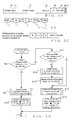
- Fig. 7 is a flow chart showing an example operational sequence of a transmission channel reserving process that is performed periodically by the CPU of each of the devices on the audio network 6.
- the CPU of the device in question sets as "x" a difference between the value of the parameter DCN stored in the memory of the device and the number KN of the transmission channels currently reserved by the device. If the value of "x" is a positive value (x > 0) (i..e, "Positive" at step S101), it means that the number DCN of the transmission channels to be reserved have not yet been reserved by (for) the device, and thus, the CPU of the device goes to step S102, where the CPU performs a process for reserving the x transmission channels shown in Fig.
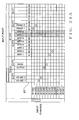
- each of transmission channel allocation state display portions 74 located immediately under the input port name display portions 73, is displayed a mark indicating whether any transmission channel is currently allocated to the corresponding input port.
- a mark " - " indicates that no transmission channel is required because the corresponding input port is one of the input ports (local ports) of the engine 2
- a mark " ⁇ " indicates that an output ON/OFF state of an audio signal from the input port (signal supply source SS) to the audio network 6 is currently set at OFF
- a mark “*" indicates that a transmission channel is currently allocated to the input port (signal supply source SS).
- Each transmission channel allocation state display portion 74 with no mark indicates that no transmission channel is currently allocated to the input port (signal supply source SS).
- channel name display portions are provided in a left-end vertical region of the screen for indicating the names of all of the output channels of the engine 2.
- a mark i.e., mark " ⁇ " or "*", or no-mark blank
- the output channel is currently allocated to any one of the transmission channels.
- an audio signal is transmitted from the output channel via the audio network 6, namely, one transmission channel is set as a connection destination of each of the output channels.
- the device names, slot names and output port names of the individual devices In each of the grids between the individual horizontal rows representing the output channels and the vertical columns representing the output ports is displayed a connection mark that indicates a connection state of the cell.
- the human operator can set or cancel an output patch for allocating the output port (signal supply destination), displayed in the corresponding vertical column, to the output channel (signal supply source) displayed in the corresponding horizontal row.
- the CPU of the control device at step S8 determines, on the basis of information stored in the memory of the control device, whether any connection is currently set in the clicked-on cell. If no connection mark is currently displayed in the cell, then the CPU determines at step S8 that no connection is in the currently set clicked-on cell (NO determination at step S8). If, on the other hand, the mark "•", " ⁇ " or " ⁇ " is currently displayed in the cell, the CPU determines at step S8 that a connection is currently set in the clicked-on cell (YES determination at step S8).
- step S19 If there has been found such a transmission channel having the audio signal of the signal supply source SS, put thereon (YES determination at step S19), it means that a "transmission connection" pertaining to the signal supply source SS has already been established in the device possessing the signal supply source SS, i.e. that the signal of the signal supply source SS has already been transmitted to the audio network 6, the CPU of the control device jumps to step S21 without performing an operation of step S20.
- the CPU of the control device sets a "reception connection" in the device possessing the signal supply destination SD.
- the "reception connection” to be set here is a setting for receiving the audio signal, corresponding to the name SSN of the signal supply source SS, from the audio network 6 (i.e., a setting for allocating the transmission channel, having the name SSN put thereon, to the output port connected with the signal supply destination SD).
- the CPU of the control device rewrites, on the basis of the "reception connection", information of the output port, connected with the supply destination SD. stored in the memory of the control device.
- the CPU of the control device transmits the content of the "reception connection" to the device possessing the supply destination SD and performs remote control for rewriting "signal supply source information" stored in the memory of the device possessing the supply destination SD.
- the "signal supply source information" is indicative of a signal supply source SS (i.e., one of the signal supply sources possessed by the other devices) to which the signal supply destination SD is to be connected.
- the operations performed by the control device and other related devices at steps S20 and S21 may be summarized as follows.
- the CPU of the control device at steps S20 and S21 functions as a connection setting section that, in response to a connection instruction given by the human operator, makes a setting for connecting a desired signal supply destination SD to a desired signal supply source SS (i.e., sets a "transmission connection” in the device possessing the supply source SS and a "reception connection” in the device possessing the supply destination SD), to thereby rewrite signal supply destination information and signal supply source information stored in the memory of the device possessing the supply source SS and in the memory of the device possessing the supply destination SD through remote control, performed by the control device, on the devices having the supply destination SD and supply source SS.
- Fig. 12 is a flow chart showing an example operational sequence of the connection clearing process performed at step S9 or S12 of Fig. 10 .
- the CPU of the control device determines whether the signal supply source SS and the signal supply destination SD corresponding to the cell that is an object of the connection clearing process (i.e., the clicked-on cell or "other cell" at step S12) are both in a same device.
- the CPU of the control device checks presence of any device, other than the device for which the reception connection has been cleared, has currently set therein a reception connection containing the name SSN. If there is no other device which has currently set therein the reception connection containing the name SSN (NO determination at step S26), the CPU of the control device goes to step S27 in order to clear the transmission connection of the supply source SS set in the device possessing the supply source SS. Namely, the CPU of the control device not only clears the signal supply destination information for the supply source SS stored in the memory of the control device, but also performs remote control for clearing the signal supply destination information of (i.e., pertaining to) the supply source SS stored in the memory of the device possessing the supply source SS.
- Fig. 14 is a flow chart showing an example operational sequence of an event process performed by any one of the devices when a connection between a signal supply source SS and a signal supply destination SD in (i.e., possessed by) the same device has been cleared at step S23 above. Namely, once a connection between a signal supply source SS and a signal supply destination SD in the same device has been cleared in the control device, that device cancels the patch setting by which the signal supply destination SD is currently allocated as the output destination of the supply source SS (step S29 of Fig. 14 ). In this way, the supply destination SD is disconnected from the supply source SS.
- Such patch setting cancellation within the same device can be performed using a conventionally-known technique.
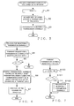
- Fig. 15 is a flow chart showing an example operational sequence of a connection updating process performed periodically by each of the devices connected to the audio network 6.
- the device in which a transmission connection has been set by the operation of step S20 stores, into its memory, signal supply destination information indicative of the transmission connection
- the device in which a reception connection has been set by the operation of step S21 stores, into its memory, signal supply source information indicative of the reception connection.
- a network input patch setting (actualization or implementation of the transmission connection) is executed on the basis of the stored signal supply destination information
- a network output patch setting (actualization or implementation of the reception connection) is executed on the basis of the stored signal supply source information.
- the audio signal output to the audio network 6 can be set ON or OFF for each signal supply source SS.
- ON/OFF of the audio signal output can be set as desired for each signal supply source SS by the human operator operating the control device or any one of the I/O devices to which the signal supply source SS is currently connected.
- Each signal supply source SS of which the audio signal output is OFF is not subjected to implementation of a corresponding transmission connection.
- the mark " ⁇ " is displayed in the corresponding transmission channel allocation state display portion 74 of the patch setting screen (see Fig. 8C ).
- the human operator can set a priority (level) for each signal supply source SS via the control device. Details of the priority setting will be discussed later.
- control can be performed such that a transmission connection of a higher priority is actualized or implemented preferentially.
- the operation of step S30 is performed by a background process of the device.
- the CPU of the device allocates one currently-unallocated transmission channel (i), included among the transmission channels reserved thereby through the aforementioned transmission channel reserving process, as a transmission channel to be used for transmission of the audio signal of the supply source SS.
- the CPU of the device sets, as "i", the channel number of the currently-unallocated transmission channel and sets that transmission channel (i) as a transmission channel to be used for transmission of the audio signal of the supply source SS.
- the CPU of the device also sets, as information SSN(i), a pair of the name SSN of the supply source SS, for which the transmission connection is to be implemented, and the channel number (i). In the aforementioned manner, one of the transmission channels reserved by the device through the aforementioned transmission channel reserving process is allocated to the supply source SS designated by the human operator clicking on the patch setting screen.
- the CPU of each of the devices at step S35 functions as a transmission setting section which makes a setting for allocating one transmission channel to the supply source SS on the basis of a set transmission connection (signal supply destination information) and outputting an audio signal from the supply source SS via the allocated transmission channel, and implements the transmission connection pertaining to a patch setting for a cell clicked by the human operator. Further, the CPU of the device stores, into its memory, information indicative of connection states pertaining to the implemented transmission connection (such as information indicative of the name SSN of the supply source SS, input terminal connected with the supply source SS and transmission channel (i)).
- the instant embodiment can extremely simplify the control for implementing each transmission connection to be performed by each of the devices.
- a device possessing only a relatively simple control means can perform the aforementioned operation without involving an excessive load.
- a conventionally-known process for allocating a transmission channel of a network of the Ethernet (registered trademark) standard or the like is arranged to allocate a transmission channel to a connection setting between nodes (signal supply source and destination), but not arranged to allocate a transmission channel to a transmitting node (signal supply source) of a connection setting as in the above-described embodiment of the present invention namely, the conventionally-known process does not employ closed control performed in the transmitting node. Therefore, in a case where priority control is performed for a connection setting between nodes in an ordinary network in the conventionally-known manner, which of the nodes is a signal supply source of the connection setting would influence the priority control; as a consequence, the process for performing the priority control in the conventionally-known manner would be complicated. By contrast, the above-described embodiment of the present invention allows the priority control to be performed through an extremely simple process.
- the device in question can determine a transmission channel (i), via which to receive an audio signal, for each signal supply destination SD possessed by the device, and can receive the audio signal via the thus-determined transmission channel.
- the device possessing the supply source SS can perform the operation for implementing the reception connection to start reception of the audio signal, without performing negotiation with the device possessing the signal supply source SS.
- the device possessing the signal supply destination SD implements the reception connection by connecting the supply destination SD to the transmission channel having the audio signal of the supply source SS put thereon, it can continue its audio signal receiving operation even when some of the other devices in the system has come to be no longer present in the mixing system due to powering-off or disconnection from the network 6. Namely, even when some of the devices in the system has come to be no longer present in the mixing system due to powering-off or disconnection from the network 6, the mixing system can continue the audio signal transmitting and receiving operations between the other devices remaining in the system.
- the instant embodiment can limit output bands of the device (i.e., transmission bands or channels to be used by the device for audio signal transmission).
- the CPU 10 of the control device displays the connection mark " ⁇ " in the corresponding cell through the operation of step S15 of Fig. 10 and warns the human operator that the transmission channels are lacking.
- connection mark "•” is displayed, through the operation of step S15 of Fig. 10 , in the cell, corresponding to the patch setting in question, on the patch setting screen displayed on the control device. Further, when the transmission connection has not been implemented due to lack of a currently-unused transmission channel (NO determination at step S33), the connection mark " ⁇ " is displayed, through the aforementioned operation of step S15 of Fig. 10 , in the corresponding cell.
- the device which has the unimplemented transmission connection, allocates an available or empty transmission channel, having occurred because of the increase in the number KN of the reserved transmission channels, to the supply source SS corresponding to the transmission connection during the connection updating process.
- a device possessing a signal supply destination SD to be connected to the supply source SS implements a reception connection corresponding to the transmission connection having so far been left unimplemented during the connection updating process. Because the connection updating process is performed periodically by each of the devices connected to the audio network 6, the patch setting having so far been left unimplemented can be automatically implemented if the number KN of the transmission channels, reserved by the device for which the transmission connection has been set, increases as noted above.
- Fig. 16 is a flow chart showing an example operational sequence of an event process performed, in response to clearing or cancellation by the control device of a reception connection at step S24 of Fig. 12 , by a device for which the reception connection has been canceled (i.e., a device possessing a signal supply destination SD).
- the CPU of the device possessing the signal supply destination SD identifies a signal supply source SS, connected with the supply destination SD, on the basis of signal supply source information of (i.e. pertaining to) the supply destination SD corresponding to the canceled reception connection, and it also identifies a reception port connected with the supply destination SD and a transmission channel i of the reception port. If there is no connection from the reception port to the supply destination SD (NO determination at step S49), it means that no reception connection has been made in the device, and thus, the CPU of the device ends the instant event process.
- step S49 If there is a connection from the reception port to the supply destination SD (YES determination at step S49), the CPU of the device proceeds to step S50, where it disconnects the connection between the supply destination SD and the reception port. Then, at step S51, the CPU of the device cancels the signal reception by the device via the transmission channel i if no other supply destination than the disconnected supply destination SD is currently connected to the above-mentioned reception port, so as to eliminate the reception port. Further, if there is another supply destination currently connected to the reception port (NO determination at step S49), the CPU of the device maintains the reception port at step S51 without canceling the signal reception of the transmission channel i.
- the device may be constructed to always receive transmission channels not reserved by the device, or all transmission channels registered in the R signal list (i.e., transmission channels reserved by all of the devices on the network) and generate all reception ports for reception of these transmission channels. In such a case, there is no longer the need for dynamically set and cancel reception of the transmission channels, so that the reception connection setting process included in the connection updating process shown in Fig. 15 and the reception connection cancellation process shown in Fig. 16 can be simplified.
- step S53 If the information SSN(i) corresponding to the supply source name SSN is in the T signal list (YES determination at step S53), the CPU of the device goes to step S54, where it disconnects a connection between a transmission port of the identified transmission channel (i) and the supply source SS of the name SSN and also sets "null" into the information SSN(i). Then, the CPU of the device not only deletes the record of the information SSN(i) from its own T signal list, but also transmits the information SSN(i), having "null” set therein, to the other devices on the audio network 6. In this manner, the transmission connection is canceled.
- Fig. 18 is a flow chart showing an example operational sequence of a process performed by any one of the devices when information SSN(L) has been received from another of the devices on the network 6.
- the CPU of the device determines whether or not the value of the received information SSN(i) is "null". If the received information SSN(i) has the name SSN of a signal supply source SS set therein (NO determination at step S55), the CPU of the device adds the received information SSN(i) to the R signal list possessed by that device (step S56). In this manner, the device stores the name SSN of the supply source SS of an audio signal being transmitted from the other device in association with a transmission channel (i) being used for the audio signal transmission.
- the instant embodiment has been described above as constructed to record information SSN(i) which is not “null” into the R signal list of each of the devices on the audio network 6, it may be constructed to record information SSN(i) of all transmission channels reserved by the other devices, including information SSN(i) which is "null", into the R signal list of each of the devices.
- the T signal list can be said for the T signal list as well.
- the instant embodiment has been described above as constructed to record information SSN(i), which is not "null", into the T signal list of each of the devices on the audio network 6, it may be constructed to record information SSN(i) of all transmission channels reserved by the device, including information SSN(i) which is "null", into the T signal list of the device.
- the CPU of the control device when a connection setting is to be made between a signal supply source SS (input port) and an input channel of the engine 2, the CPU of the control device not only sets a transmission connection for a device possessing the supply source SS (step S20 of Fig. 11 ) but also sets a reception connection for the engine 2 having the input channel (step S21 of Fig. 11 ). Then, the CPU of the engine 2 sets reception of a transmission channel i having an audio signal of the supply source SS put thereon and connects a reception port of the transmission channel i to the input channel (steps S45 and S46 of Fig. 15 ).
- the CPU of the control device cancels the reception connection for the engine 2 having the input channel (step S24 of Fig. 11 ), but also cancels the transmission connection for the device possessing the supply source SS (step S27 of Fig. 12 ) as necessary. Then, the CPU of the engine 2 disconnects the connection from the reception port of the transmission channel i to the input channel, and, if there is no other input channel currently connected to that reception port, the CPU of the engine 2 cancels the reception of the transmission channel i to eliminate the reception port (steps S50 and S51 of Fig. 16 ).
- the engine 2 sets, as a transmission channel (i) one of transmission channels reserved thereby, generates a transmission port of the transmission channel (i) and connects the above-mentioned output channel to the transmission port of the transmission channel (i) (step S35 of Fig. 15 ).
- the engine 2 sets, as information SSN(i), a pair of the name SSN of an output signal of the output channel (i.e., name SSN of the supply source SS of the signal) and the transmission channel (i), and it transmits the information SSN(i) to the other devices on the network 6 but also registers the information SSN(i) into its own T signal list.
- each of the I/O devices 3 - 5 is equipped with the simplified operator (user) interface (i.e., simplified UI) 25 including a display section and controls, so that a local patch setting within the I/O can be made using the simplified UI 25.
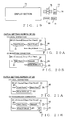
- Fig. 19 is a diagram showing an example construction of the simplified UI 25 of each of the I/O devices 3 - 5.
- the human operator can call up the patch setting screen for a signal supply destination SD (i.e., SD patch setting screen) or signal supply source SS (i.e., SS patch setting screen) to the display section 75 of the I/O device, and can make a patch setting for the supply destination SD or supply source SS via the patch setting screen displayed on the display section 75.
- the patch setting for a supply destination SD is a setting for connecting a signal supply source SS (input port), possessed by the device, or an input from the network 6 to the signal supply destination SD (output port) possessed by the device.
- the patch setting for a supply source SS is a setting for connecting a signal supply destination SD (output port), possessed by the device, or an output of the network 6 to the signal supply source SS (input port) possessed by the device.
- a "To:" portion 81 shown in each of Figs. 20A and 20B the human operator can select one output port from a list of all of the output ports possessed by the I/O device.
- the name of the selected output port is displayed in the "To:” portion 81.
- the output port name comprises a pair of the slot number ("Slot2" in the figures) of a slot having the output port (output terminal) attached hereto and the terminal number ("Port3" in the figures) of the output terminal.
- the name SSN assigned to the supply source SS connected to the input port (input terminal) selected via the "From:” portion 82 is displayed in a "Name:” portion 83.
- a rectangular frame is not depicted in the "Name:” portion 83 unlike in the other display portions 81 and 82.
- the "Name:” portion 83 is not arranged to allow the human operator to select a name via the "Name:” portion 83.
- Fig. 20B shows an example where an input from the network 6 has been selected by the human operator via the "From:” portion 82 so that "Network” is displayed in the "From:” portion 82.
- the human operator can select, via the "Name:” portion 83, one supply source name SSN from among a plurality of names SSN(i), registered in the R signal list possessed by the I/O device, using the controls 76 - 80.
- the human operator can designate an audio signal to be received from the audio network 6.
- Figs. 21A and 21B are diagrams showing an example construction of the SS patch setting screen.
- character strings "#1 I/O Device" and "Input Port Patch”, displayed in an uppermost horizontal row of the screen, indicate that the instant patch setting screen is a screen for setting a patch of an input port (i.e., signal supply source connected to the input port) of the first I/O device.
- the patch section in the instant embodiment is constructed to allow each input port (signal supply source SS) to be connected to a plurality of connection destinations (a plurality of output ports or audio network 6)
- the SS patch setting screen in each of the I/O devices in the instant embodiment is designed to allow each output port (signal supply destination SD) to be connected to only one output port (one signal supply destination SD).
- a transmission channel allocation state is displayed by an indicator 85 next to the right of the signal output ON/OFF setting portion 84. Namely, the indicator 85 is illuminated when a transmission channel is currently allocated to the input port, but deilluminated when no transmission channel is allocated to the input port.
- step S58 If the signal supply destination SD (output port) whose connection destination has been changed is currently connected with a reception port of any transmission channel (YES determination at step S58), the CPU of the I/O device goes to step S59, where it disconnects the connection between the supply destination SD (output port) and the reception port to thereby terminate reception of an audio signal from the transmission channel of the reception port. Thus, the existing reception connection of the output port is cleared or canceled.
- the CPU of the I/O device determines whether the signal supply source SS (input port) whose connection destination has been changed is currently connected to a transmission port of any transmission channel. If the last connection destination of the input port is an "output" to the network 6 and the transmission connection thereof has been implemented, it means that the input port is currently connected to a transmission port. Otherwise, namely, if the last connection destination is a local output port, no transmission channel has not been allocated to the supply source SS (i.e., the transmission connection thereof has not been implemented), or if there has been no connection destination selected for the supply source SS till immediately before the change, a NO determination is made at step S63.
- step S63 If the signal supply source SS (input port) whose connection destination has been changed is currently connected to a transmission port of any transmission channel (YES determination at step S63), the CPU of the I/O device goes to step S64, where it searches its own T signal list for information SSN(i) corresponding to the name SSN of the supply source SS, and identifies the channel number (i) of a transmission channel being used as an output destination of the supply source SS.
- the CPU of the I/O device sets "null” into the information SSN(i) corresponding to the identified channel number (i), disconnects the connection between the transmission port of the transmission channel of the channel number (i) and the input port (supply source SS) and thereby terminate transmission of the transmission channel (i). Also, the CPU of the I/O device transmits the information SSN(i), having "null” set therein, to the other devices on the network 6, and deletes the information SSN(i) from its own T signal list.
- step S67 sets a currently selected signal supply destination SD as a connection destination of the supply source SS and changes signal supply destination information of the supply source SS and signal supply source information of the supply destination SD stored in its own memory. Then, the supply destination SD and the supply source SS are connected with each other on the basis of the thus-set connection. This operation is similar to the operation of step S28 shown in Fig. 13 .
- the content of the set connection is notified to the control device, which in turn stores the information of the connection (between the supply source SS and supply destination SD of the I/O device) into its own current memory.
- step S66 the CPU of the I/O device proceeds to step S68, where it changes the signal supply source information of the supply destination SD stored in its own memory and sets a transmission connection for connecting a transmission channel (i), having put thereon an audio signal of a name SSN selected via the "Name:” portion 83, to an output port (supply destination SD) displayed in the "To:” portion 81. Then, the thus-set transmission connection is implemented when the I/O device has performed the connection updating process of Fig. 15 .
- control device changes the connection information (signal supply destination information of the supply source SS of the I/O device and signal supply destination information of a supply source SS of another device on the network 6 receiving an audio signal of the supply source SS) stored in its own current memory.
- each of the devices on the network 6 allows the human operator to set, via the simplified UI 25 of the device, a connection between a signal supply source SS of the device and another device via the network 6 (i.e. a transmission connection of the supply source SS) and a connection between a signal supply destination SD of the device and another device via the network 6 (i.e. a transmission connection of the supply destination SD). Also, these transmission and reception connections are implemented within the limits of transmission channels reserved by the transmission channel reserving process of Fig. 6 performed by that device. Namely, even when the control device controlling the entire mixing system is not present, e. g. when the control device is not currently connected to the network 6 or the power supply to the control device is OFF, each of the devices on the network 6 can control its necessary signal paths on its own.
- Fig. 24 is a flow chart showing an example operational sequence of a process performed by the CPU of any one of the devices in response to human operator's operation of the signal output ON/OFF setting portion 84 displayed on the SS patch setting screen of the device.
- the CPU of the device inverts the current ON/OFF setting of the portion 84, at step S69.
- the CPU of the I/O device switches the signal output ON/OFF parameter to "OFF” and stores the switched state into the memory. Then, if a transmission port of any transmission channel (i) is currently connected to the signal supply source SS (input port) for which the signal output has been switched to OFF (YES determination at step S71), operations similar to steps S64 and S65 are performed.
- the CPU of the I/O device disconnects the connection between the input port and the transmission port (transmission channel (i)), sets “null” into the information SSN(L) for the supply source SS connected to the input port, transmits the information SSN(i), having "null” set therein, to the other devices on the network 6 and deletes the information SSN(i) from its own T signal list, at steps S72 and S73.
- the CPU of the I/O device switches the signal output ON/OFF parameter to "ON” and stores the switched signal output state into the memory, after which the CPU ends the instant process. Because the supply source SS, for which the signal output ON has been set, was in the signal output OFF state before the current operation, the supply source SS is not an object of the aforementioned detection at step S30 of Fig. 15 , and the transmission connection therefor has been implemented. However, now that the signal output state has been set to "ON" through the current operation, the transmission connection for the supply source SS is placed in an implementable state through the connection updating process of Fig. 15 .
- Fig. 25 is a flow chart showing an example operational sequence of a process performed by the CPU of any one of the devices when a supply source name SSN has been changed in the "Name" portion 83 of the SS patch setting screen of Fig. 21A or 21B .
- the CPU of the device assigns the device ID of the device to the name ssn, having been set by the human operator, to thereby generate a name SSN. Because of a precondition that the name ssn should not duplicate within the same device, each name SSN can be unique in the mixing system by the name ssn being assigned a device ID. If a transmission port of any transmission channel (i) is currently connected to the signal supply source SS of which the name has been changed (YES determination at step S75), the CPU of the device sets, as "i", the channel number of the channel connected to the supply source SS.
- the lock ON/OFF setting of each supply source SS or supply destination SD is made in accordance with an instruction given via the control device. Namely, in the region (current memory) provided in the memory of the control device for storing current operating states of the mixing system are stored data of a lock ON/OFF setting of each of signal supply destinations SD (output ports) and signal supply sources SS (input ports) connected to the individual devices. Further, in the memory of each of the devices is stored data of a lock ON/OFF setting of each of signal supply destinations SD (output ports) and signal supply sources SS (input ports) connected to that device.
- Fig. 26 is a flow chart showing an example operational sequence of a process performed by the CPU of the control device when an instruction has been given, for example, through lock ON/OFF designating operation performed by the human operator via the control device, for setting a lock ON or OFF state for a signal supply destination SD or signal supply source SS.
- the CPU of the control device switches the lock ON/OFF setting data of the destination SD or source SS, stored in the current memory, to ON and sets the new lock setting of the supply destination SD or supply source SS in the device possessing the destination SD or source SS (step S79). Then, the CPU of the device possessing the supply destination SD or supply source SS switches the lock ON/OFF setting data of the destination SD or source SS, stored in the memory of the device, to ON. Thus, the lock mark 86 on the patch setting screen is switched to indicate a lock ON state.
- the instant embodiment can give priorities to the signal supply sources SS (input ports) and signal supply destinations SD (output ports). Namely, either of two different, i.e. high and low, priority levels is set for a transmission connection of each of the signal supply sources SS and for a reception transmission for each of the signal supply destinations SD in accordance with the lock ON/OFF settings.
- step S30 the CPU of each of the devices detects transmission connections to be implemented and also sorts the detected transmission connections in accordance with the priorities of the detected transmission connections, as set forth above.
- the CPU of each of the devices implements the "transmission connections" sequentially in a decreasing order of the priorities.
- a limited number of transmission channels reserved by the device can be more reliably allocated to the transmission connections having higher priorities.
- the transmission connection of a signal supply source SS having a low priority is left unimplemented more positively than the transmission connection having a high priority.
- the human operator himself can control which of a plurality of transmission connections set (at step S14 of Fig. 11 ) should be implemented preferentially and which of the transmission connections should be left unimplemented.
- the human operator can perform operation for setting the number DCN of transmission channels to be reserved at a desired number.
- Such operation for setting the number DCN of transmission channels to be reserved is performed, for example, when transmission channels are to be newly reserved or when transmission channels already reserved by the device are to be returned (i.e., transmission channels allocated to the device are to be released (from the transmission channel reservation).
- the human operator can perform the operation for setting the number DCN via the control device or the device for which the new number DCN is to be set.
- the value of "x" is a negative value (x ⁇ 0) (i..e, "Negative" at step S82), it means that the number DCN is smaller than the number KN, and thus, the CPU of the device returns (or releases) a predetermined number, corresponding to the absolute value of "x", of the transmission channels. Because, in this case, the value of "x" is a negative value (- x) and the predetermined number of transmission channels corresponding thereto is the absolute value of "x”.
- the CPU of the device compares the number of transmission channels not currently being used for audio signal transmission (i.e., currently-unused transmission channels) among the reserved transmission channels and the number x of transmission channels to be returned.
- the CPU of the device determines one or more transmission channels to be released (from the transmission channel reservation) on the basis of the priorities of the individual signal supply sources SS allocated to the currently-used transmission channels and sets, as "i", the channel numbers of the one or more determined transmission channels; namely, "i” here indicates one or more channel numbers that correspond to the number of deficient transmission channels (i.e., a difference between the number of the currently-unused transmission channels and the value of "x").
- the one or more transmission channels to be released are determined on the basis of the priorities of the signal supply sources SS.
- priority control determines the transmission channels to be released sequentially, beginning with a transmission channel connected to a transmission channel connected to a low-priority signal supply source SS (i.e., signal supply source SS set in the lock OFF state), while excluding, from objects of the release, as many transmission channels connected to high-priority signal supply sources as possible.
- the aforementioned priority control allows connections between desired high-priority signal supply source SS and transmission channels to be relatively difficult to cancel.
- priority order between transmission channels of a same priority level may be determined in accordance with any suitable rule, such as order of the channel numbers of the transmission channels.
- the CPU of the device controls the display section (i.e., P display 15, simplified UI 25 or monitor of the PC 7) of the device, which is being currently operated by the human operator, to make a warning display.
- this warning display presents to the human operator that transmission channel release is going to be carried out, but also inquires the human operator whether the instant process should be continued or canceled.
- the display presenting to the human operator that transmission channel release is going to be carried out may include the name SSN of each signal supply source SS to be disconnected through the release of the corresponding transmission channel.
- the CPU of the device discontinues the instant process and sets the value of the number DCN, updated through the operation of the human operator, back to the last value (i.e., value immediately before the start of the instant process).
- the CPU of the device disconnects, for each of the transmission channels (i) determined at step S85, the connection between the transmission channel and the supply source SS (i.e., cancels the allocation of the supply source SS to the transmission channel). Then, the CPU of the device sets "null" into information SSN(i) corresponding to the transmission channels (i), and transmits the information SSN(i) to the other devices on the audio network 6. In response to the transmission of the information SSN(i), each of the other devices performs the process of Fig. 8 and deletes each of the corresponding information SSN(i) from its R signal list.
- step S88 the CPU of the device stops audio signal transmission using the "x" transmission channels (i) for which connections with the supply sources SS have been disconnected at step S87 above.
- the device returns these transmission channels (i) to the audio network 6. Now that these transmission channels (i) have been released from the allocation to the device in question, the transmission channels (i) become empty or available channels (see Fig. 2C ).
- the CPU of the device at step S88 stops audio signal transmission using the "x" transmission channels (i) of the unused transmission channels and returns (releases) these transmission channels (i) to the network 6. Because the unused transmission channels (i.e., transmission channels not currently connected to any supply sources SS) are transmitting zero-level (or silent) signals, the CPU of the device stops such zero-level signal transmission at step S88.
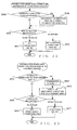
- Fig. 28 is a flow chart showing an example operational sequence of a process performed by a CPU of a control device when the control device has been newly connected to the mixing system in operation, e.g. when the control device has been newly physically connected to the audio network 6, when a power supply to the control device, which was being physically connected to the audio network 6 with the power supply to the control device turned off, has been turned on, or the like.
- the CPU of the newly connected control device gathers information about all of the other devices connected to the audio network 6, and then it determines, on the basis of the gathered information about all of the other devices, whether or not any other control device is currently present in the mixing system, at step S90. If any other control device is currently present in the mixing system (YES determination at step S90), the CPU of the newly connected control device goes to step S91 to perform an operation for synchronizing the stored content of the current memory with that of the other, i.e. existing, control device. Namely, the stored content of the current memory of the existing control device is overwritten into the current memory of the newly connected control. In this way, the stored content of the current memory of the newly connected control can be made to conform to the current states of the mixing system in operation.
- the CPU of the newly connected control device goes to step S92, where, on the basis of the information about all of the other devices gathered at step S89, the CPU associates the data stored in its own current memory with the devices connected to the network 6. Namely, the CPU of the newly connected control device identifies, from among information about one more devices stored in the current memory of the newly connected control device, those of the one more devices whose actual hardware is present in the mixing system and those of one more devices whose actual hardware is not present in the mixing system. Each device whose information is stored in the current memory and coincides with the actual hardware in the mixing system is referred to herein as an "associated device". For each device whose information is not stored in the current memory of the newly connected control device although its actual hardware is present in the mixing system, the CPU of the newly connected control device generates information corresponding to that device and associates the thus-generated information with the actual hardware.
- the CPU of the newly connected control device designates one of the devices associated at step S92.
- step S94 If information about the designated associated device, stored in the current memory of the newly connected control device, includes a signal supply source SS and signal supply destination SD set in the lock ON state, then the CPU of the newly connected control device goes to step S94, where it overwrites connection information (signal supply source information and signal supply destination information), pertaining to the signal supply source SS and signal supply destination SD set in the lock ON state and stored in the current memory, into the memory of the designated associated device.
- connection information signal supply source information and signal supply destination information
- a setting of a transmission connection of the supply source SS set in the lock ON state and a setting of a reception connection of the supply destination SD set in the lock ON state, stored in the newly connected control device are given a priority over corresponding settings stored in the designated associated device (i.e., settings of the connections actually implemented at that time).
- the CPU of the newly connected control device overwrites the connection information, stored in the current memory of the newly connected control device, with the connection information (i.e., supply destination information of each signal supply source SS other than the supply source SS set in the lock ON state and supply source information of each signal supply destination SD other than the supply destination SD set in the lock ON) stored in the memory of the designated associated device.
- connection information i.e., supply destination information of each signal supply source SS other than the supply source SS set in the lock ON state and supply source information of each signal supply destination SD other than the supply destination SD set in the lock ON
- settings such a setting of a transmission connection of each supply source SS set in the lock OFF (i.e., non-locked) state and a setting of a reception connection of each supply destination SD the lock OFF (i.e., non-locked) state
- settings are given a priority over those stored in the current memory of the newly connected control device.
- the CPU of the newly connected control device overwrites the other data pertaining to the designated associated device, stored in the current memory of the newly connected control device, with the other data stored in the memory of the designated associated device. Namely, when the control device has been newly connected to the mixing system, information other than supply destination information of each signal supply source SS and supply source information of each signal supply destination SD (i.e., other settings actually implemented at that time) is given a priority over such information (other settings) stored in the current memory of the newly connected control device.
- the CPU of the newly connected control device designates another one of the devices associated at step S92 and performs the synchronizing process at and after steps S94 above (i.e., loop process of steps S94 - S98). Then, the CPU of the newly connected control device ends the instant process after having completed the aforementioned synchronizing process on all of the associated devices (YES determination at step S98).
- Essential points of the process of Fig. 28 are summarized as follows in terms of the novel arrangement that, when a control device has been newly connected to the mixing system, the process of Fig. 28 leaves or maintains settings of a transmission connection of a particular signal supply source SS and a connection between particular devices which were stored till immediately before the new connection of the control device (namely, settings of each of the other devices than the newly-connected control device are given a priority).
- the essential points of the process of Fig. 28 are summarized focusing on synchronization of settings of a connection (signal supply destination information and signal supply source information) of a non-locked signal supply source SS.
- the CPU of the newly-connected control device can function as a synchronization section which updates, on the basis of connection information stored in its own current memory, all of signal supply destination information and signal supply source information stored in the respective memories of the devices on the network 6, except for signal supply destination information and signal supply source information pertaining to the identified supply source SS (i.e., signal supply destination information indicative of a signal supply destination of the identified supply source SS and signal supply source information of (pertaining to) the supply destination receiving a signal of the supply source SS) (which corresponds to the operation of step S94 for updating the content of the memory of each of the devices), and which updates, on the basis of the signal supply destination information and signal supply source information pertaining to the identified supply source SS, the connection information stored in the own current memory of the newly connected control device (which corresponds to the operation of step S95 for changing the stored content of the current memory).
- signal supply destination information and signal supply source information pertaining to the identified supply source SS i.e., signal supply destination information indicative of a signal supply destination of the identified supply
- the CPU of the newly connected control device can function as an identification section that, by setting a lock ON/OFF state for each of the signal supply sources SS or signal supply destinations SD, possessed by the plurality of devices 1 - 5, through the process of Fig. 26 , identifies predetermined two mutually-connected devices (i.e., a device possessing a non-locked signal supply source SS and a device possessing a non-locked signal supply destination SD as a connection destination of the supply source SS) of the plurality of devices (already-associated devices) of the mixing system.
- the CPU of the control device can function as a synchronization section which updates, on the basis of the connection information stored in its own current memory, all of signal supply destination information and signal supply source information stored in the respective memories of the devices, except for signal supply destination information and signal supply source information pertaining to a connection between the two identified devices (namely, signal supply destination information indicative of a signal supply destination of a non-locked signal supply source SS of one of the two identified devices and signal supply source information indicative of a signal supply source of a non-locked signal supply destination SD) (which corresponds to the operation of step S94 for changing the content of the memory of each of the devices), and which updates, on the basis of the signal supply destination information and signal supply source information pertaining to the connection between the two devices, the connection information stored in the own current memory of the newly connected control device (which corresponds to the operation of step S95 for changing the stored content of the current memory).
- the CPU of the control device can function as a synchronization section which updates, on the basis of the connection information stored in its own current memory, signal supply destination information and signal supply source information pertaining to a connection between the two identified devices (namely, signal supply destination information indicative of a signal supply destination of a locked signal supply source SS of one of the two identified devices and signal supply source information indicative of a signal supply destination of a locked signal supply destination SD of the other identified device) included among signal supply destination information and signal supply source information stored in the respective memories of the devices (which corresponds to the operation of step S94 for changing the content of the memory of each of the devices), and which updates, on the basis of the signal supply destination information and signal supply source information pertaining to the connection between the two devices, the connection information stored in the own current memory of the newly connected control device (which corresponds to the operation of step S95 for changing the stored content of the current memory).
- the process of Fig. 28 summarized in terms of the foregoing three aspects can leave or maintain, a setting of a transmission connection of a signal supply source SS identified by the identification section and a setting of a connection between particular devices that were stored till immediately before the new connection of the control device to the mixing system.
- the instant embodiment can leave or maintain data of the setting of the transmission connection of a signal supply source SS and data of the setting of the connection between particular devices that were stored till immediately before the connection of the control device to the mixing system, by the control device controlling, through the process of Fig. 28 , a direction of data synchronization between the control device and each of the other devices on the basis of a lock ON/OFF setting of each signal supply sources SS stored in its own memory.
- the instant embodiment can maintain settings of any desired transmission paths of the mixing system.
- a transmission connection pertaining to each patch setting designated by the human operator on any one of the patch setting screens shown in Figs. 8A - 8C and Figs. 9A and 9B is implemented automatically by the connection updating process performed by any one of the devices (step S35). Namely, whether or not any one of transmission channels reserved by the device should be allocated to a signal supply source SS (input port) pertaining to the transmission connection to be implemented is automatically determined in the above-described embodiment.
- Another embodiment of the present invention may be constructed to allow the human operator to designate, via the patch setting screen, a path setting of a transmission frame (i.e., connection between a signal supply source and a transmission channel) in addition to a connection between a signal supply source and a signal supply destination.
- a path setting of a transmission frame i.e., connection between a signal supply source and a transmission channel
- the human operator can perform transmission channel (transmission band) management by himself (herself).
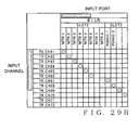
- Figs. 29A and 29B are diagrams showing patch setting screens via which the human operator can set dual patch settings.
- Fig. 29A shows an input patch setting screen of the engine 2, which is generally similar in construction of the screen of Fig. 8C , except that channel numbers of transmission channels connected to the input ports are displayed in portions 87 of Fig. 29A that correspond in position to the transmission channel allocation state display portions 74 of Fig. 8C provided in corresponding relation to the input ports.
- a connection mark " ⁇ " indicative of a patch setting/cancellation between an input port and an input channel is displayed in some cells as in Fig. 8C .
- Gray-out columns (representing input ports to which signals of MRT7 and MRT8 are supplied) indicate that no transmission channels are currently allocated to the input ports.
- lock ON/OFF settings for a transmission connection of a signal supply source SS and a reception connection of a signal supply destination SD can be instructed by the human operator separately for each signal supply source SS and each signal supply destination SD.
- an instruction for automatically making a lock ON setting may be generated depending on types of a signal supply source SS and a signal supply destination SD.
- a transmission channel may be automatically allocated to the signal supply source SS, even when the human operator does not make a patch setting for the supply source SS and hence no transmission connection is not set for the supply source SS, as long as the signal output ON/OFF setting of the signal supply source SS is "ON" (i.e., as long as the transmission connection is detected at step S30) and regardless of whether the supply source SS is currently connected to an input port (i.e., without making the determination of step S34).
- a transmission channel for transmitting an intercommunicating signal is automatically allocated to the supply source SS.
- a monitoring channel there is fixedly provided a monitoring output terminal (output port) in each of the devices, such as the console 1, and transmission channels for the monitoring channel is essential; thus, transmission channels may allocated automatically to the corresponding input port and output port so that necessary paths can be automatically reserved.
- the present invention is not so limited, and the present invention may be constructed to allow the human operator to set any one of many priority levels for each signal supply source SS.
- the present invention is not so limited, and the present invention may be constructed in such a manner that lock ON/OFF settings for signal supply sources SS and signal supply destinations of any one of the devices are made via the simplified UI 25 of that device.
- any other device than the I/O devices 3 - 5 in the mixing system may be provided with an operator interface capable of displaying and operating similar patch setting screens, a display section and an operation section for operating the display section, and this other device may make patch settings for signal supply sources SS and signal supply destinations SD (input and output ports) of the device so that it can implement transmission connections or reception connections, pertaining to the patch settings, within the limits of the transmission channels reserved by the device.
- signal supply sources SS and signal supply destinations SD input and output ports
- the patch setting operation via the control device may be performed using any suitable conventionally-known construction, instead of the aforementioned construction where a patch setting is instructed using a matrix diagram (i.e., patch setting screen) indicating signal supply sources and signal supply destinations as described above in relation to the embodiments of the present invention.
- a matrix diagram i.e., patch setting screen
- the control device may either be implemented by a device incorporated in one of the devices constituting the mixing system, or be implemented by a device provided independently of, or separately from, the devices constituting the mixing system.
- the control device may be incorporated in any one of the devices, other than the console 1, constituting the mixing system.
- such control devices may be incorporated in a plurality of the devices constituting the mixing system.
- the control device may be a PC connected directly to the network 6 rather than being connected to the PC I/O of any one of the devices connected to the network.
- the mixing system of the present invention may be embodied as audio mixing systems (audio systems) for use in various scenes, such as PA (Public Address) systems in concert venues, large-scale events, etc., local-area broadcasting systems in facilities like department stores and schools, and recording systems in music recording studios.
- PA Public Address
Landscapes
- Engineering & Computer Science (AREA)
- Computer Networks & Wireless Communication (AREA)
- Signal Processing (AREA)
- Human Computer Interaction (AREA)
- Circuit For Audible Band Transducer (AREA)
- Stereophonic System (AREA)
- Small-Scale Networks (AREA)
- Data Exchanges In Wide-Area Networks (AREA)
Priority Applications (2)
| Application Number | Priority Date | Filing Date | Title |
|---|---|---|---|
| EP12189991.8A EP2552056B1 (de) | 2009-03-24 | 2010-03-22 | Vorrichtung und Verfahren zur Steuerung einer Eingabe-/Ausgabevorrichtung in einem Audiosystem |
| EP11165849A EP2357760B1 (de) | 2009-03-24 | 2010-03-22 | Système audio |
Applications Claiming Priority (4)
| Application Number | Priority Date | Filing Date | Title |
|---|---|---|---|
| JP2009072912A JP5326720B2 (ja) | 2009-03-24 | 2009-03-24 | 音響システム |
| JP2009072913A JP5665164B2 (ja) | 2009-03-24 | 2009-03-24 | 音響システム及び装置 |
| JP2009072911A JP5223752B2 (ja) | 2009-03-24 | 2009-03-24 | 音響システム |
| JP2009072910A JP5665163B2 (ja) | 2009-03-24 | 2009-03-24 | 音響システムの経路設定方法及び経路設定装置 |
Related Child Applications (3)
| Application Number | Title | Priority Date | Filing Date |
|---|---|---|---|
| EP12189991.8A Division EP2552056B1 (de) | 2009-03-24 | 2010-03-22 | Vorrichtung und Verfahren zur Steuerung einer Eingabe-/Ausgabevorrichtung in einem Audiosystem |
| EP11165849.8 Division-Into | 2011-05-12 | ||
| EP12189991.8 Division-Into | 2012-10-25 |
Publications (3)
| Publication Number | Publication Date |
|---|---|
| EP2234339A2 true EP2234339A2 (de) | 2010-09-29 |
| EP2234339A3 EP2234339A3 (de) | 2010-10-06 |
| EP2234339B1 EP2234339B1 (de) | 2012-12-05 |
Family
ID=42356026
Family Applications (3)
| Application Number | Title | Priority Date | Filing Date |
|---|---|---|---|
| EP10157137A Not-in-force EP2234339B1 (de) | 2009-03-24 | 2010-03-22 | Pfadeinstellungsverfahren für Audiosystem sowie Audiosystem |
| EP12189991.8A Not-in-force EP2552056B1 (de) | 2009-03-24 | 2010-03-22 | Vorrichtung und Verfahren zur Steuerung einer Eingabe-/Ausgabevorrichtung in einem Audiosystem |
| EP11165849A Not-in-force EP2357760B1 (de) | 2009-03-24 | 2010-03-22 | Système audio |
Family Applications After (2)
| Application Number | Title | Priority Date | Filing Date |
|---|---|---|---|
| EP12189991.8A Not-in-force EP2552056B1 (de) | 2009-03-24 | 2010-03-22 | Vorrichtung und Verfahren zur Steuerung einer Eingabe-/Ausgabevorrichtung in einem Audiosystem |
| EP11165849A Not-in-force EP2357760B1 (de) | 2009-03-24 | 2010-03-22 | Système audio |
Country Status (3)
| Country | Link |
|---|---|
| US (1) | US8452433B2 (de) |
| EP (3) | EP2234339B1 (de) |
| CN (1) | CN101848125B (de) |
Families Citing this family (8)
| Publication number | Priority date | Publication date | Assignee | Title |
|---|---|---|---|---|
| CN102404131B (zh) * | 2010-07-29 | 2015-03-25 | 株式会社理光 | 通讯终端、通讯管理系统、通讯系统、声音输入部登录方法 |
| JP5682508B2 (ja) * | 2011-08-29 | 2015-03-11 | ヤマハ株式会社 | ミキシングシステム |
| JP5861986B2 (ja) * | 2012-01-24 | 2016-02-16 | ヤマハ株式会社 | ミキシングシステム |
| KR102051588B1 (ko) | 2013-01-07 | 2019-12-03 | 삼성전자주식회사 | 휴대 단말기의 오디오 컨텐츠 재생 방법 및 그 장치 |
| US9311022B2 (en) | 2013-10-07 | 2016-04-12 | Dell Products L.P. | System and method for improved communication in a storage network |
| JP7002657B2 (ja) * | 2017-12-28 | 2022-01-20 | 北京小米移動軟件有限公司 | 伝送方向情報を確定する方法及び装置 |
| DE102019208461A1 (de) * | 2019-06-11 | 2020-12-17 | Robert Bosch Gmbh | Audiogeräteanordnung, Konfigurationseinrichtung, Verfahren und Computerprogramm |
| CN116166214A (zh) * | 2022-11-28 | 2023-05-26 | 亿咖通(湖北)技术有限公司 | 车载音频播放方法、系统及控制器 |
Citations (2)
| Publication number | Priority date | Publication date | Assignee | Title |
|---|---|---|---|---|
| US20020122559A1 (en) | 2001-03-05 | 2002-09-05 | Fay Todor J. | Audio buffers with audio effects |
| US20070025568A1 (en) | 2005-07-29 | 2007-02-01 | Yamaha Corporation | Mixing apparatus and computer program therefor |
Family Cites Families (14)
| Publication number | Priority date | Publication date | Assignee | Title |
|---|---|---|---|---|
| JPH04207432A (ja) | 1990-11-30 | 1992-07-29 | Toshiba Corp | Avネットワーク・システム |
| EP1102435B1 (de) * | 1999-10-29 | 2006-01-11 | Sony Corporation | Verfahren und System zur Nutzung einer Vielzahl von Übertragungsleitungen und Einstellung des Verbindungsbetriebsverfahrens |
| US20030023975A1 (en) * | 2001-03-02 | 2003-01-30 | Microsoft Corporation | Enhanced music services for television |
| JP3916953B2 (ja) * | 2001-12-28 | 2007-05-23 | 日本テキサス・インスツルメンツ株式会社 | 可変時分割多重伝送システム |
| WO2004066661A1 (ja) * | 2003-01-23 | 2004-08-05 | Fujitsu Limited | 通信資源管理装置 |
| EP2410681A3 (de) * | 2005-03-31 | 2012-05-02 | Yamaha Corporation | Steuergerät für ein Musiksystem bestehend aus mehreren Geräten die über ein Netz mit einander verbunden sind, und integriertes Computerprogramm für die Steuerung vom Musiksystem |
| JP5094004B2 (ja) | 2005-10-20 | 2012-12-12 | パナソニック株式会社 | データ中継装置及びデータ中継方法 |
| US7590128B2 (en) * | 2005-12-28 | 2009-09-15 | Motorola, Inc. | Method and system for setting up a media session in a telecommunications network |
| JP4893985B2 (ja) | 2006-03-22 | 2012-03-07 | ヤマハ株式会社 | オーディオネットワークシステム |
| JP4930757B2 (ja) * | 2006-03-22 | 2012-05-16 | ヤマハ株式会社 | オーディオネットワークシステム |
| JP2007259182A (ja) | 2006-03-24 | 2007-10-04 | Yamaha Corp | 論理接続自動設定装置及びプログラム |
| EP1901483B1 (de) | 2006-09-13 | 2014-11-05 | Yamaha Corporation | Netzwerksystem und Audiosignalprozessor |
| JP4341714B2 (ja) | 2006-09-13 | 2009-10-07 | ヤマハ株式会社 | ネットワークシステム及び音響信号処理装置 |
| JP5186871B2 (ja) * | 2007-10-10 | 2013-04-24 | ヤマハ株式会社 | ネットワークオーディオシステムのチャンネルパッチングシステム |
-
2010
- 2010-03-22 EP EP10157137A patent/EP2234339B1/de not_active Not-in-force
- 2010-03-22 EP EP12189991.8A patent/EP2552056B1/de not_active Not-in-force
- 2010-03-22 EP EP11165849A patent/EP2357760B1/de not_active Not-in-force
- 2010-03-24 US US12/731,092 patent/US8452433B2/en not_active Expired - Fee Related
- 2010-03-24 CN CN201010139728.4A patent/CN101848125B/zh not_active Expired - Fee Related
Patent Citations (2)
| Publication number | Priority date | Publication date | Assignee | Title |
|---|---|---|---|---|
| US20020122559A1 (en) | 2001-03-05 | 2002-09-05 | Fay Todor J. | Audio buffers with audio effects |
| US20070025568A1 (en) | 2005-07-29 | 2007-02-01 | Yamaha Corporation | Mixing apparatus and computer program therefor |
Also Published As
| Publication number | Publication date |
|---|---|
| EP2357760A1 (de) | 2011-08-17 |
| EP2552056B1 (de) | 2016-03-16 |
| US20100246830A1 (en) | 2010-09-30 |
| CN101848125A (zh) | 2010-09-29 |
| EP2357760B1 (de) | 2012-10-31 |
| EP2234339A3 (de) | 2010-10-06 |
| CN101848125B (zh) | 2014-07-16 |
| EP2552056A1 (de) | 2013-01-30 |
| EP2234339B1 (de) | 2012-12-05 |
| US8452433B2 (en) | 2013-05-28 |
Similar Documents
| Publication | Publication Date | Title |
|---|---|---|
| EP2357760B1 (de) | Système audio | |
| US8527076B2 (en) | Control apparatus for music system comprising a plurality of equipments connected together via network, and integrated software for controlling the music system | |
| US7158488B2 (en) | Communication control apparatus and method | |
| EP2485445B1 (de) | Verfahren zur Durchführung einen Netzanschluss in einem Audionetzwerksystem | |
| EP2288056A2 (de) | Audiosignalverarbeitungssystem mit einer Mehrzahl durch ein Audionetzwerk verbundenen Geräten | |
| CN1870129B (zh) | 音乐系统的控制装置和控制音乐系统的集成软件 | |
| JP5665164B2 (ja) | 音響システム及び装置 | |
| JP5223752B2 (ja) | 音響システム | |
| JP5665163B2 (ja) | 音響システムの経路設定方法及び経路設定装置 | |
| JP5655889B2 (ja) | 経路設定方法及び音響装置 | |
| JP5326720B2 (ja) | 音響システム | |
| JP4735373B2 (ja) | ネットワークを介して接続された複数の機器で構成される音楽システムの制御装置及び該音楽システムを制御するための統合的なソフトウェアプログラム | |
| JP4952023B2 (ja) | ネットワークを介して接続された複数の機器で構成される音楽システムの制御装置及び該音楽システムを制御するための統合的なソフトウェアプログラム | |
| JP4952024B2 (ja) | ネットワークを介して接続された複数の機器で構成される音楽システムの制御装置及び該音楽システムを制御するための統合的なソフトウェアプログラム | |
| JP2008009102A (ja) | 集団音楽教習システム |
Legal Events
| Date | Code | Title | Description |
|---|---|---|---|
| PUAI | Public reference made under article 153(3) epc to a published international application that has entered the european phase |
Free format text: ORIGINAL CODE: 0009012 |
|
| PUAL | Search report despatched |
Free format text: ORIGINAL CODE: 0009013 |
|
| AK | Designated contracting states |
Kind code of ref document: A2 Designated state(s): AT BE BG CH CY CZ DE DK EE ES FI FR GB GR HR HU IE IS IT LI LT LU LV MC MK MT NL NO PL PT RO SE SI SK SM TR |
|
| AX | Request for extension of the european patent |
Extension state: AL BA ME RS |
|
| AK | Designated contracting states |
Kind code of ref document: A3 Designated state(s): AT BE BG CH CY CZ DE DK EE ES FI FR GB GR HR HU IE IS IT LI LT LU LV MC MK MT NL NO PL PT RO SE SI SK SM TR |
|
| AX | Request for extension of the european patent |
Extension state: AL BA ME RS |
|
| 17P | Request for examination filed |
Effective date: 20110404 |
|
| 17Q | First examination report despatched |
Effective date: 20110530 |
|
| GRAP | Despatch of communication of intention to grant a patent |
Free format text: ORIGINAL CODE: EPIDOSNIGR1 |
|
| GRAS | Grant fee paid |
Free format text: ORIGINAL CODE: EPIDOSNIGR3 |
|
| GRAA | (expected) grant |
Free format text: ORIGINAL CODE: 0009210 |
|
| AK | Designated contracting states |
Kind code of ref document: B1 Designated state(s): AT BE BG CH CY CZ DE DK EE ES FI FR GB GR HR HU IE IS IT LI LT LU LV MC MK MT NL NO PL PT RO SE SI SK SM TR |
|
| REG | Reference to a national code |
Ref country code: GB Ref legal event code: FG4D |
|
| REG | Reference to a national code |
Ref country code: CH Ref legal event code: EP |
|
| REG | Reference to a national code |
Ref country code: AT Ref legal event code: REF Ref document number: 587787 Country of ref document: AT Kind code of ref document: T Effective date: 20121215 |
|
| REG | Reference to a national code |
Ref country code: IE Ref legal event code: FG4D |
|
| REG | Reference to a national code |
Ref country code: DE Ref legal event code: R096 Ref document number: 602010003905 Country of ref document: DE Effective date: 20130131 |
|
| REG | Reference to a national code |
Ref country code: AT Ref legal event code: MK05 Ref document number: 587787 Country of ref document: AT Kind code of ref document: T Effective date: 20121205 |
|
| PG25 | Lapsed in a contracting state [announced via postgrant information from national office to epo] |
Ref country code: LT Free format text: LAPSE BECAUSE OF FAILURE TO SUBMIT A TRANSLATION OF THE DESCRIPTION OR TO PAY THE FEE WITHIN THE PRESCRIBED TIME-LIMIT Effective date: 20121205 Ref country code: NO Free format text: LAPSE BECAUSE OF FAILURE TO SUBMIT A TRANSLATION OF THE DESCRIPTION OR TO PAY THE FEE WITHIN THE PRESCRIBED TIME-LIMIT Effective date: 20130305 Ref country code: SE Free format text: LAPSE BECAUSE OF FAILURE TO SUBMIT A TRANSLATION OF THE DESCRIPTION OR TO PAY THE FEE WITHIN THE PRESCRIBED TIME-LIMIT Effective date: 20121205 Ref country code: ES Free format text: LAPSE BECAUSE OF FAILURE TO SUBMIT A TRANSLATION OF THE DESCRIPTION OR TO PAY THE FEE WITHIN THE PRESCRIBED TIME-LIMIT Effective date: 20130316 Ref country code: FI Free format text: LAPSE BECAUSE OF FAILURE TO SUBMIT A TRANSLATION OF THE DESCRIPTION OR TO PAY THE FEE WITHIN THE PRESCRIBED TIME-LIMIT Effective date: 20121205 |
|
| REG | Reference to a national code |
Ref country code: NL Ref legal event code: VDEP Effective date: 20121205 |
|
| REG | Reference to a national code |
Ref country code: LT Ref legal event code: MG4D |
|
| PG25 | Lapsed in a contracting state [announced via postgrant information from national office to epo] |
Ref country code: SI Free format text: LAPSE BECAUSE OF FAILURE TO SUBMIT A TRANSLATION OF THE DESCRIPTION OR TO PAY THE FEE WITHIN THE PRESCRIBED TIME-LIMIT Effective date: 20121205 Ref country code: PL Free format text: LAPSE BECAUSE OF FAILURE TO SUBMIT A TRANSLATION OF THE DESCRIPTION OR TO PAY THE FEE WITHIN THE PRESCRIBED TIME-LIMIT Effective date: 20121205 Ref country code: GR Free format text: LAPSE BECAUSE OF FAILURE TO SUBMIT A TRANSLATION OF THE DESCRIPTION OR TO PAY THE FEE WITHIN THE PRESCRIBED TIME-LIMIT Effective date: 20130306 Ref country code: LV Free format text: LAPSE BECAUSE OF FAILURE TO SUBMIT A TRANSLATION OF THE DESCRIPTION OR TO PAY THE FEE WITHIN THE PRESCRIBED TIME-LIMIT Effective date: 20121205 |
|
| PG25 | Lapsed in a contracting state [announced via postgrant information from national office to epo] |
Ref country code: AT Free format text: LAPSE BECAUSE OF FAILURE TO SUBMIT A TRANSLATION OF THE DESCRIPTION OR TO PAY THE FEE WITHIN THE PRESCRIBED TIME-LIMIT Effective date: 20121205 |
|
| PG25 | Lapsed in a contracting state [announced via postgrant information from national office to epo] |
Ref country code: EE Free format text: LAPSE BECAUSE OF FAILURE TO SUBMIT A TRANSLATION OF THE DESCRIPTION OR TO PAY THE FEE WITHIN THE PRESCRIBED TIME-LIMIT Effective date: 20121205 Ref country code: SK Free format text: LAPSE BECAUSE OF FAILURE TO SUBMIT A TRANSLATION OF THE DESCRIPTION OR TO PAY THE FEE WITHIN THE PRESCRIBED TIME-LIMIT Effective date: 20121205 Ref country code: BG Free format text: LAPSE BECAUSE OF FAILURE TO SUBMIT A TRANSLATION OF THE DESCRIPTION OR TO PAY THE FEE WITHIN THE PRESCRIBED TIME-LIMIT Effective date: 20130305 Ref country code: IS Free format text: LAPSE BECAUSE OF FAILURE TO SUBMIT A TRANSLATION OF THE DESCRIPTION OR TO PAY THE FEE WITHIN THE PRESCRIBED TIME-LIMIT Effective date: 20130405 Ref country code: CZ Free format text: LAPSE BECAUSE OF FAILURE TO SUBMIT A TRANSLATION OF THE DESCRIPTION OR TO PAY THE FEE WITHIN THE PRESCRIBED TIME-LIMIT Effective date: 20121205 Ref country code: BE Free format text: LAPSE BECAUSE OF FAILURE TO SUBMIT A TRANSLATION OF THE DESCRIPTION OR TO PAY THE FEE WITHIN THE PRESCRIBED TIME-LIMIT Effective date: 20121205 |
|
| PG25 | Lapsed in a contracting state [announced via postgrant information from national office to epo] |
Ref country code: PT Free format text: LAPSE BECAUSE OF FAILURE TO SUBMIT A TRANSLATION OF THE DESCRIPTION OR TO PAY THE FEE WITHIN THE PRESCRIBED TIME-LIMIT Effective date: 20130405 Ref country code: RO Free format text: LAPSE BECAUSE OF FAILURE TO SUBMIT A TRANSLATION OF THE DESCRIPTION OR TO PAY THE FEE WITHIN THE PRESCRIBED TIME-LIMIT Effective date: 20121205 Ref country code: NL Free format text: LAPSE BECAUSE OF FAILURE TO SUBMIT A TRANSLATION OF THE DESCRIPTION OR TO PAY THE FEE WITHIN THE PRESCRIBED TIME-LIMIT Effective date: 20121205 |
|
| PLBE | No opposition filed within time limit |
Free format text: ORIGINAL CODE: 0009261 |
|
| STAA | Information on the status of an ep patent application or granted ep patent |
Free format text: STATUS: NO OPPOSITION FILED WITHIN TIME LIMIT |
|
| PG25 | Lapsed in a contracting state [announced via postgrant information from national office to epo] |
Ref country code: DK Free format text: LAPSE BECAUSE OF FAILURE TO SUBMIT A TRANSLATION OF THE DESCRIPTION OR TO PAY THE FEE WITHIN THE PRESCRIBED TIME-LIMIT Effective date: 20121205 Ref country code: MC Free format text: LAPSE BECAUSE OF NON-PAYMENT OF DUE FEES Effective date: 20130331 |
|
| 26N | No opposition filed |
Effective date: 20130906 |
|
| PG25 | Lapsed in a contracting state [announced via postgrant information from national office to epo] |
Ref country code: CY Free format text: LAPSE BECAUSE OF FAILURE TO SUBMIT A TRANSLATION OF THE DESCRIPTION OR TO PAY THE FEE WITHIN THE PRESCRIBED TIME-LIMIT Effective date: 20121205 |
|
| REG | Reference to a national code |
Ref country code: FR Ref legal event code: ST Effective date: 20131129 |
|
| PG25 | Lapsed in a contracting state [announced via postgrant information from national office to epo] |
Ref country code: IT Free format text: LAPSE BECAUSE OF FAILURE TO SUBMIT A TRANSLATION OF THE DESCRIPTION OR TO PAY THE FEE WITHIN THE PRESCRIBED TIME-LIMIT Effective date: 20121205 |
|
| REG | Reference to a national code |
Ref country code: IE Ref legal event code: MM4A |
|
| REG | Reference to a national code |
Ref country code: DE Ref legal event code: R097 Ref document number: 602010003905 Country of ref document: DE Effective date: 20130906 |
|
| PG25 | Lapsed in a contracting state [announced via postgrant information from national office to epo] |
Ref country code: FR Free format text: LAPSE BECAUSE OF NON-PAYMENT OF DUE FEES Effective date: 20130402 Ref country code: HR Free format text: LAPSE BECAUSE OF FAILURE TO SUBMIT A TRANSLATION OF THE DESCRIPTION OR TO PAY THE FEE WITHIN THE PRESCRIBED TIME-LIMIT Effective date: 20130731 Ref country code: IE Free format text: LAPSE BECAUSE OF NON-PAYMENT OF DUE FEES Effective date: 20130322 |
|
| PG25 | Lapsed in a contracting state [announced via postgrant information from national office to epo] |
Ref country code: MT Free format text: LAPSE BECAUSE OF FAILURE TO SUBMIT A TRANSLATION OF THE DESCRIPTION OR TO PAY THE FEE WITHIN THE PRESCRIBED TIME-LIMIT Effective date: 20121205 |
|
| REG | Reference to a national code |
Ref country code: CH Ref legal event code: PL |
|
| PG25 | Lapsed in a contracting state [announced via postgrant information from national office to epo] |
Ref country code: CH Free format text: LAPSE BECAUSE OF NON-PAYMENT OF DUE FEES Effective date: 20140331 Ref country code: LI Free format text: LAPSE BECAUSE OF NON-PAYMENT OF DUE FEES Effective date: 20140331 |
|
| PG25 | Lapsed in a contracting state [announced via postgrant information from national office to epo] |
Ref country code: SM Free format text: LAPSE BECAUSE OF FAILURE TO SUBMIT A TRANSLATION OF THE DESCRIPTION OR TO PAY THE FEE WITHIN THE PRESCRIBED TIME-LIMIT Effective date: 20121205 |
|
| PG25 | Lapsed in a contracting state [announced via postgrant information from national office to epo] |
Ref country code: TR Free format text: LAPSE BECAUSE OF FAILURE TO SUBMIT A TRANSLATION OF THE DESCRIPTION OR TO PAY THE FEE WITHIN THE PRESCRIBED TIME-LIMIT Effective date: 20121205 |
|
| PG25 | Lapsed in a contracting state [announced via postgrant information from national office to epo] |
Ref country code: MK Free format text: LAPSE BECAUSE OF FAILURE TO SUBMIT A TRANSLATION OF THE DESCRIPTION OR TO PAY THE FEE WITHIN THE PRESCRIBED TIME-LIMIT Effective date: 20121205 Ref country code: HU Free format text: LAPSE BECAUSE OF FAILURE TO SUBMIT A TRANSLATION OF THE DESCRIPTION OR TO PAY THE FEE WITHIN THE PRESCRIBED TIME-LIMIT; INVALID AB INITIO Effective date: 20100322 Ref country code: LU Free format text: LAPSE BECAUSE OF NON-PAYMENT OF DUE FEES Effective date: 20130322 |
|
| PGFP | Annual fee paid to national office [announced via postgrant information from national office to epo] |
Ref country code: DE Payment date: 20160315 Year of fee payment: 7 |
|
| PGFP | Annual fee paid to national office [announced via postgrant information from national office to epo] |
Ref country code: GB Payment date: 20160316 Year of fee payment: 7 |
|
| REG | Reference to a national code |
Ref country code: DE Ref legal event code: R119 Ref document number: 602010003905 Country of ref document: DE |
|
| GBPC | Gb: european patent ceased through non-payment of renewal fee |
Effective date: 20170322 |
|
| PG25 | Lapsed in a contracting state [announced via postgrant information from national office to epo] |
Ref country code: DE Free format text: LAPSE BECAUSE OF NON-PAYMENT OF DUE FEES Effective date: 20171003 |
|
| PG25 | Lapsed in a contracting state [announced via postgrant information from national office to epo] |
Ref country code: GB Free format text: LAPSE BECAUSE OF NON-PAYMENT OF DUE FEES Effective date: 20170322 |