EP2233902B1 - Belastungsdetektor - Google Patents
Belastungsdetektor Download PDFInfo
- Publication number
- EP2233902B1 EP2233902B1 EP08861483.9A EP08861483A EP2233902B1 EP 2233902 B1 EP2233902 B1 EP 2233902B1 EP 08861483 A EP08861483 A EP 08861483A EP 2233902 B1 EP2233902 B1 EP 2233902B1
- Authority
- EP
- European Patent Office
- Prior art keywords
- linear body
- load
- detection device
- tip end
- hollow tube
- Prior art date
- Legal status (The legal status is an assumption and is not a legal conclusion. Google has not performed a legal analysis and makes no representation as to the accuracy of the status listed.)
- Not-in-force
Links
- 238000001514 detection method Methods 0.000 claims description 123
- 238000003780 insertion Methods 0.000 claims description 90
- 230000037431 insertion Effects 0.000 claims description 90
- 238000005452 bending Methods 0.000 claims description 44
- 201000008450 Intracranial aneurysm Diseases 0.000 claims description 40
- 230000010102 embolization Effects 0.000 claims description 36
- 210000004204 blood vessel Anatomy 0.000 claims description 32
- 238000004364 calculation method Methods 0.000 claims description 15
- 238000012549 training Methods 0.000 claims description 7
- 238000003825 pressing Methods 0.000 claims description 6
- 238000010586 diagram Methods 0.000 description 26
- 238000012545 processing Methods 0.000 description 11
- 238000000034 method Methods 0.000 description 7
- 210000000709 aorta Anatomy 0.000 description 5
- 210000001627 cerebral artery Anatomy 0.000 description 5
- 210000001367 artery Anatomy 0.000 description 4
- 230000015572 biosynthetic process Effects 0.000 description 4
- 230000007274 generation of a signal involved in cell-cell signaling Effects 0.000 description 4
- 238000003786 synthesis reaction Methods 0.000 description 4
- 238000006243 chemical reaction Methods 0.000 description 3
- 238000005286 illumination Methods 0.000 description 3
- 210000001715 carotid artery Anatomy 0.000 description 2
- 238000000605 extraction Methods 0.000 description 2
- 230000010354 integration Effects 0.000 description 2
- 239000002504 physiological saline solution Substances 0.000 description 2
- 210000002385 vertebral artery Anatomy 0.000 description 2
- 210000000621 bronchi Anatomy 0.000 description 1
- 230000008878 coupling Effects 0.000 description 1
- 238000010168 coupling process Methods 0.000 description 1
- 238000005859 coupling reaction Methods 0.000 description 1
- 230000007423 decrease Effects 0.000 description 1
- 230000000694 effects Effects 0.000 description 1
- 238000011156 evaluation Methods 0.000 description 1
- 238000002474 experimental method Methods 0.000 description 1
- 238000002594 fluoroscopy Methods 0.000 description 1
- 210000002751 lymph Anatomy 0.000 description 1
- 239000002184 metal Substances 0.000 description 1
- 238000012986 modification Methods 0.000 description 1
- 230000004048 modification Effects 0.000 description 1
- 238000013421 nuclear magnetic resonance imaging Methods 0.000 description 1
- 230000003287 optical effect Effects 0.000 description 1
- 239000011347 resin Substances 0.000 description 1
- 229920005989 resin Polymers 0.000 description 1
- 238000003325 tomography Methods 0.000 description 1
- 210000000626 ureter Anatomy 0.000 description 1
- 230000000007 visual effect Effects 0.000 description 1
Images






Classifications
-
- A—HUMAN NECESSITIES
- A61—MEDICAL OR VETERINARY SCIENCE; HYGIENE
- A61B—DIAGNOSIS; SURGERY; IDENTIFICATION
- A61B17/00—Surgical instruments, devices or methods
- A61B17/12—Surgical instruments, devices or methods for ligaturing or otherwise compressing tubular parts of the body, e.g. blood vessels or umbilical cord
-
- A—HUMAN NECESSITIES
- A61—MEDICAL OR VETERINARY SCIENCE; HYGIENE
- A61B—DIAGNOSIS; SURGERY; IDENTIFICATION
- A61B17/00—Surgical instruments, devices or methods
- A61B17/12—Surgical instruments, devices or methods for ligaturing or otherwise compressing tubular parts of the body, e.g. blood vessels or umbilical cord
- A61B17/12022—Occluding by internal devices, e.g. balloons or releasable wires
- A61B17/12099—Occluding by internal devices, e.g. balloons or releasable wires characterised by the location of the occluder
- A61B17/12109—Occluding by internal devices, e.g. balloons or releasable wires characterised by the location of the occluder in a blood vessel
- A61B17/12113—Occluding by internal devices, e.g. balloons or releasable wires characterised by the location of the occluder in a blood vessel within an aneurysm
-
- A—HUMAN NECESSITIES
- A61—MEDICAL OR VETERINARY SCIENCE; HYGIENE
- A61B—DIAGNOSIS; SURGERY; IDENTIFICATION
- A61B17/00—Surgical instruments, devices or methods
- A61B17/12—Surgical instruments, devices or methods for ligaturing or otherwise compressing tubular parts of the body, e.g. blood vessels or umbilical cord
- A61B17/12022—Occluding by internal devices, e.g. balloons or releasable wires
- A61B17/12131—Occluding by internal devices, e.g. balloons or releasable wires characterised by the type of occluding device
- A61B17/1214—Coils or wires
-
- A—HUMAN NECESSITIES
- A61—MEDICAL OR VETERINARY SCIENCE; HYGIENE
- A61B—DIAGNOSIS; SURGERY; IDENTIFICATION
- A61B5/00—Measuring for diagnostic purposes; Identification of persons
- A61B5/68—Arrangements of detecting, measuring or recording means, e.g. sensors, in relation to patient
- A61B5/6846—Arrangements of detecting, measuring or recording means, e.g. sensors, in relation to patient specially adapted to be brought in contact with an internal body part, i.e. invasive
- A61B5/6885—Monitoring or controlling sensor contact pressure
-
- A—HUMAN NECESSITIES
- A61—MEDICAL OR VETERINARY SCIENCE; HYGIENE
- A61B—DIAGNOSIS; SURGERY; IDENTIFICATION
- A61B90/00—Instruments, implements or accessories specially adapted for surgery or diagnosis and not covered by any of the groups A61B1/00 - A61B50/00, e.g. for luxation treatment or for protecting wound edges
- A61B90/06—Measuring instruments not otherwise provided for
-
- A—HUMAN NECESSITIES
- A61—MEDICAL OR VETERINARY SCIENCE; HYGIENE
- A61B—DIAGNOSIS; SURGERY; IDENTIFICATION
- A61B17/00—Surgical instruments, devices or methods
- A61B2017/00017—Electrical control of surgical instruments
- A61B2017/00115—Electrical control of surgical instruments with audible or visual output
-
- A—HUMAN NECESSITIES
- A61—MEDICAL OR VETERINARY SCIENCE; HYGIENE
- A61B—DIAGNOSIS; SURGERY; IDENTIFICATION
- A61B17/00—Surgical instruments, devices or methods
- A61B17/12—Surgical instruments, devices or methods for ligaturing or otherwise compressing tubular parts of the body, e.g. blood vessels or umbilical cord
- A61B17/12022—Occluding by internal devices, e.g. balloons or releasable wires
- A61B2017/1205—Introduction devices
-
- A—HUMAN NECESSITIES
- A61—MEDICAL OR VETERINARY SCIENCE; HYGIENE
- A61B—DIAGNOSIS; SURGERY; IDENTIFICATION
- A61B34/00—Computer-aided surgery; Manipulators or robots specially adapted for use in surgery
- A61B34/10—Computer-aided planning, simulation or modelling of surgical operations
- A61B2034/101—Computer-aided simulation of surgical operations
- A61B2034/102—Modelling of surgical devices, implants or prosthesis
-
- A—HUMAN NECESSITIES
- A61—MEDICAL OR VETERINARY SCIENCE; HYGIENE
- A61B—DIAGNOSIS; SURGERY; IDENTIFICATION
- A61B34/00—Computer-aided surgery; Manipulators or robots specially adapted for use in surgery
- A61B34/20—Surgical navigation systems; Devices for tracking or guiding surgical instruments, e.g. for frameless stereotaxis
- A61B2034/2046—Tracking techniques
- A61B2034/2061—Tracking techniques using shape-sensors, e.g. fiber shape sensors with Bragg gratings
-
- A—HUMAN NECESSITIES
- A61—MEDICAL OR VETERINARY SCIENCE; HYGIENE
- A61B—DIAGNOSIS; SURGERY; IDENTIFICATION
- A61B34/00—Computer-aided surgery; Manipulators or robots specially adapted for use in surgery
- A61B34/30—Surgical robots
- A61B2034/301—Surgical robots for introducing or steering flexible instruments inserted into the body, e.g. catheters or endoscopes
-
- A—HUMAN NECESSITIES
- A61—MEDICAL OR VETERINARY SCIENCE; HYGIENE
- A61B—DIAGNOSIS; SURGERY; IDENTIFICATION
- A61B90/00—Instruments, implements or accessories specially adapted for surgery or diagnosis and not covered by any of the groups A61B1/00 - A61B50/00, e.g. for luxation treatment or for protecting wound edges
- A61B90/06—Measuring instruments not otherwise provided for
- A61B2090/064—Measuring instruments not otherwise provided for for measuring force, pressure or mechanical tension
-
- A—HUMAN NECESSITIES
- A61—MEDICAL OR VETERINARY SCIENCE; HYGIENE
- A61B—DIAGNOSIS; SURGERY; IDENTIFICATION
- A61B90/00—Instruments, implements or accessories specially adapted for surgery or diagnosis and not covered by any of the groups A61B1/00 - A61B50/00, e.g. for luxation treatment or for protecting wound edges
- A61B90/06—Measuring instruments not otherwise provided for
- A61B2090/064—Measuring instruments not otherwise provided for for measuring force, pressure or mechanical tension
- A61B2090/065—Measuring instruments not otherwise provided for for measuring force, pressure or mechanical tension for measuring contact or contact pressure
-
- A—HUMAN NECESSITIES
- A61—MEDICAL OR VETERINARY SCIENCE; HYGIENE
- A61B—DIAGNOSIS; SURGERY; IDENTIFICATION
- A61B90/00—Instruments, implements or accessories specially adapted for surgery or diagnosis and not covered by any of the groups A61B1/00 - A61B50/00, e.g. for luxation treatment or for protecting wound edges
- A61B90/36—Image-producing devices or illumination devices not otherwise provided for
- A61B90/37—Surgical systems with images on a monitor during operation
- A61B2090/376—Surgical systems with images on a monitor during operation using X-rays, e.g. fluoroscopy
-
- A—HUMAN NECESSITIES
- A61—MEDICAL OR VETERINARY SCIENCE; HYGIENE
- A61B—DIAGNOSIS; SURGERY; IDENTIFICATION
- A61B90/00—Instruments, implements or accessories specially adapted for surgery or diagnosis and not covered by any of the groups A61B1/00 - A61B50/00, e.g. for luxation treatment or for protecting wound edges
- A61B90/36—Image-producing devices or illumination devices not otherwise provided for
- A61B90/361—Image-producing devices, e.g. surgical cameras
Definitions
- the present invention relates to a load detection device and a load detection method, and particularly to a load detection device for detecting load applied to a tip end of a linear body having flexibility in inserting the linear body in a hollow tube inserted in a bending vessel.
- a catheter has conventionally been put into practical use as a linear medical appliance to be inserted in a vessel in a body such as a blood vessel, a ureter, a bronchus, an alimentary canal, or a lymph vessel.
- a catheter for example, a method of preventing rupture of a cerebral aneurysm by guiding a tip end of a catheter representing a hollow tube to a mouth of the cerebral aneurysm through a blood vessel from outside a body, thereafter inserting an embolization coil and a delivery wire representing linear bodies having flexibility in the catheter, and filling the cerebral aneurysm with the embolization coil is available. If excessive load is applied to the cerebral aneurysm by the embolization coil and the delivery wire, however, the cerebral aneurysm may be damaged.
- Patent Document 1 Japanese Patent Laying-Open No. 10-263089
- a further load detection device for detecting load applied to a tip end of a linear body having flexibility when said linear body is inserted in a hollow tube inserted in a bending vessel is known from US 2007/021742 A1 .
- a primary object of the present invention is to provide a load detection device capable of readily detecting load applied to a tip end of a thin linear body.
- a load detection device for detecting load applied to a tip end of a linear body having flexibility when the linear body is inserted in a hollow tube inserted in a bending vessel, and the load detection device includes first detection means for detecting a degree of bending of the vessel, the hollow tube or the linear body, second detection means for detecting load in insertion of the linear body in an inlet of the hollow tube, and calculation means for finding load applied to the tip end of the linear body based on a result of detection by the first and second detection means.
- the first detection means detects the degree of bending of the vessel, the hollow tube or the linear body based on an image of the vessel, the hollow tube or the linear body.
- the calculation means finds the load applied to the tip end of the linear body based on a coefficient of friction between the linear body and the hollow tube.
- the calculation means corrects the coefficient of friction based on variation in flexural rigidity depending on a position in the linear body when the flexural rigidity of the linear body varies depending on the position in the linear body.
- the coefficient of friction is measured in advance.
- the vessel is a blood vessel
- the hollow tube is a catheter
- the linear body is a treatment wire to be inserted in the catheter.
- the treatment wire includes a delivery wire and an embolization coil provided at a tip end portion of the delivery wire, for filling a cerebral aneurysm.
- the first detection means detects a degree of bending of the treatment wire when a tip end of the embolization coil enters the cerebral aneurysm, and the calculation means finds load applied to the cerebral aneurysm by the embolization coil.
- the first detection means detects a degree of bending of the blood vessel based on a three-dimensional image of the blood vessel.
- the first detection means detects a degree of bending of the treatment wire based on a two-dimensional image of the treatment wire taken by using X-rays during a surgical operation and a three-dimensional image of the blood vessel taken in advance, as superimposed on each other.
- the load detection device includes drive means for inserting the linear body in the inlet of the hollow tube, and the second detection means detects the load in insertion of the linear body based on drive force of the drive means.
- the load detection device includes a drive roller for inserting the linear body in the inlet of the hollow tube, a pressing roller rotatably supported and pressed by the drive roller with the linear body being interposed, and a motor for rotatably driving the drive roller, and the second detection means detects strain of a rotation shaft of the motor and detects the load in insertion of the linear body based on a result of that detection.
- the second detection means includes a main body portion having a through hole through which the linear body passes and an internal space provided at an intermediate point of the through hole and formed such that the linear body can curve in a prescribed direction when compressive force is applied to the linear body, and a curve sensor for detecting a degree of curve of the linear body in the internal space, and detects the load in insertion of the linear body based on the degree of curve detected by the curve sensor.
- the second detection means includes a main body portion having a through hole through which the linear body passes and formed in a bent manner such that the linear body applies a pressure in a prescribed direction when compressive force is applied to the linear body, and a pressure sensor provided at an intermediate point of the through hole, for detecting a pressure applied by the linear body in the prescribed direction, and detects the load in insertion of the linear body based on a result of detection by the pressure sensor.
- the load detection device further includes display means for visually displaying at least one load of the load in insertion of the linear body detected by the second detection means and the load applied to the tip end of the linear body found by the calculation means.
- the load detection device further includes sound generation means for generating sound indicating at least one load of the load in insertion of the linear body detected by the second detection means and the load applied to the tip end of the linear body found by the calculation means.
- the load detection device further includes recording means for recording in a video image recording medium together with an fluoroscopic image of a tip end portion of the linear body, at least one load of the load in insertion of the linear body detected by the second detection means and the load applied to the tip end of the linear body found by the calculation means.
- the load detection device is incorporated in a medical training apparatus.
- the load detection device of the present invention a degree of bending of a vessel, a hollow tube or a linear body and load in insertion of the linear body in an inlet of the hollow tube are detected, and load applied to the tip end of the linear body is found based on a result of that detection. Therefore, even when the linear body is thin, load applied to the tip end of the linear body can readily be detected.
- Fig. 1 is a diagram showing a load detection method according to Embodiment 1 of the present invention.
- a hollow tube 1 is inserted in a bending vessel (not shown) in a body and a linear body 2 having flexibility is inserted through an inlet of that hollow tube 1.
- load Fi in insertion of linear body 2 in the inlet of hollow tube 1 is detected, an image of hollow tube 1 or linear body 2 is taken, a degree of bending (for example, ⁇ / ⁇ L) of hollow tube 1 or linear body 2 is detected based on the image, and load Fo at a tip end of linear body 2 is calculated based on detected insertion load Fi and the degree of bending.
- /ds)ds means division of small angle ⁇ (s, s+ds) obtained by sectioning linear body 2 or hollow tube 1, from the inlet to the tip end of hollow tube 1, into small lengths ds by that small length ds and integration of that result with small length ds, and hence a result thereof turns out to be a total sum ⁇ of degrees of bending of linear body 2 or hollow tube 1.
- load Fo at the tip end of linear body 2 can be found based on total sum ⁇ of degrees of bending of linear body 2 or hollow tube 1 from the inlet to the tip end of hollow tube 1 and load Fi in insertion of linear body 2. Since coefficient of friction ⁇ may be different depending on combination of hollow tube 1 and linear body 2, it should only be measured in advance for each combination and selected for use depending on hollow tube 1 and linear body 2 to be used.
- Fig. 4 is a diagram showing relation between total sum ⁇ (rad) of degrees of bending of hollow tube 1 and load Fo(N) at the tip end of linear body 2 in cases where load Fi in insertion of linear body 2 is varied in three steps of Fi0, Fi1 and Fi2 (note the relation of Fi0 ⁇ Fi1 ⁇ Fi2).
- a catheter having an inner diameter ⁇ 0.56 mm is employed as hollow tube 1 and a cerebral aneurysm embolization coil having an outer diameter ⁇ 0.25 mm is employed as linear body 2.
- Three curves in Fig. 4 represent values calculated by using the following equation (12), and each point represents a measured value.
- Fo Fi - ⁇ ⁇ • exp - 2 ⁇ ⁇ - C
- the equation (12) is a corrected version of the equation (11).
- ⁇ ( ⁇ ) is a function for correcting input load Fi with ⁇
- a calculated value and a measured value are substantially equal to each other.
- load Fo(N) at the tip end decreases with increase in total sum ⁇ (rad) of degrees of bending of the catheter. Meanwhile, when total sum ⁇ (rad) of degrees of bending of the catheter is constant, load Fo(N) at the tip end also increases with increase in insertion load Fi(N).
- the delivery wire is smaller in diameter at a position close to the tip end of the coil.
- flexural rigidity of linear body 2 is not uniform across positions in linear body 2 but is different from position to position. At such a position where flexural rigidity varies, a portion lower in flexural rigidity tends to bend more, which results in greater normal reaction Fh applied to hollow tube 1.
- the equation (12) is corrected to the following equation (13). In this case, equivalent ⁇ should only be corrected.
- coefficient of friction ⁇ is expressed as a function of flexural rigidity EI(s), variation in flexural rigidity dEI(s)/ds and R(s), and this function is found in advance in experiments.
- Fo Fi • exp - 2 ⁇ ⁇ EI s , dEI s / ds , R s • R s ⁇ ds
- Fig. 5 is a diagram showing a load detection method according to Embodiment 2 of the present invention.
- Present Embodiment 2 is an application of the load detection method in Embodiment 1 to treatment for embolizing a cerebral aneurysm.
- a catheter 3 is employed as hollow tube 1, and an embolization coil 4 and a delivery wire 5 are employed as linear body 2 having flexibility.
- a base end of embolization coil 4 is coupled to a tip end of delivery wire 5.
- a cerebral aneurysm 7 has occurred in a part of a cerebral artery 6 of a patient.
- a tip end of catheter 3 is inserted in an artery of the patient from outside of his/her body and guided to a mouth of cerebral aneurysm 7 through cerebral artery 6.
- a base end of catheter 3 is connected to an outlet 8a of a Y-connector 8.
- a tip end of embolization coil 4 is inserted through an inlet 8b of Y-connector 8.
- delivery wire 5 is inserted through inlet 8b of Y-connector 8 so that cerebral aneurysm 7 is filled with embolization coil 4 through catheter 3.
- delivery wire 5 is inserted while load Fo applied to the tip end of embolization coil 4 is detected with the method shown in Embodiment 1.
- Such treatment for embolizing cerebral aneurysm 7 is given while a human body is subjected to fluoroscopy using X-ray equipment.
- catheter 3 As catheter 3 is made of resin, it is not displayed in a fluoroscopic image.
- embolization coil 4 and delivery wire 5 are made of metal, they are displayed in a fluoroscopic image.
- a fluoroscopic image is normally a two-dimensional image, however, in treatment for embolizing cerebral aneurysm 7, in order to observe a state of embolization coil 4 in cerebral aneurysm 7, the X-ray equipment is of a revolving type, so that a three-dimensional image can be created from a plurality of two-dimensional perspective images taken while the X-ray equipment revolves.
- cerebral aneurysm 7 of which blood vessel wall is thin and fragile should be filled with embolization coil 4 so as not to cause rupture of cerebral aneurysm 7 and hence force Fo applied to cerebral aneurysm 7 by embolization coil 4 is desirably measured.
- degrees of bending ⁇ of embolization coil 4 and delivery wire 5 within catheter 3 are summed based on fluoroscopic images, load Fi in inserting delivery wire 5 is measured, and force Fo applied to cerebral aneurysm 7 by embolization coil 4 is estimated.
- Fig. 6 is a block diagram showing a structure of a load detection device for performing the load detection method in present Embodiment 2.
- this load detection device includes X-ray equipment 10, an image synthesis device 11, a degree-of-bending detection device 12, an insertion load detection device 13, a storage device 14, an arithmetic processing unit 15, and a display device 16.
- X-ray equipment 10 takes a plurality of two-dimensional perspective images while revolving around a patient.
- Image synthesis device 11 creates a three-dimensional image from two-dimensional images taken by X-ray equipment 10.
- Degree-of-bending detection device 12 detects degree of bending ⁇ of embolization coil 4 and delivery wire 5 based on the three-dimensional image created by image synthesis device 11.
- Insertion load detection device 13 detects load Fi in insertion of delivery wire 5.
- Storage device 14 stores coefficient of friction ⁇ between embolization coil 4, delivery wire 5 and catheter 3 measured in advance.
- Arithmetic processing unit 15 calculates load Fo at the tip end applied to cerebral aneurysm 7 by embolization coil 4, based on degree of bending ⁇ of embolization coil 4 and delivery wire 5 detected by degree-of-bending detection device 12, load Fi in insertion of delivery wire 5 detected by insertion load detection device 13, and coefficient of friction ⁇ stored in storage device 14. This calculation method is as described in Embodiment 1.
- Display device 16 displays load Fo at the tip end. A doctor gives embolizing treatment while viewing load Fo at the tip end displayed on display device 16.
- Embodiment 2 a degree of bending of delivery wire 5 or the like during coil embolization is found in Embodiment 2
- a degree of bending of delivery wire 5 or the like before treatment is found in present Embodiment 3.
- an X-ray CT computerized tomography system
- an MRI magnetic resonance imaging system
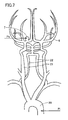
- catheter 3 is inserted from an artery at the base of a femoral region and sent from an aorta 20 through a carotid artery 21 (or a vertebral artery 22) and cerebral artery 6 to cerebral aneurysm 7.
- catheter 3 is bent along the blood vessel, bending of embolization coil 4 and delivery wire 5 that pass therethrough is also substantially the same as bending of the blood vessel. Therefore, by using a degree of bending of a blood vessel path to cerebral aneurysm 7, force applied to cerebral aneurysm 7 by embolization coil 4 can be guessed as in Embodiment 2.
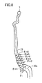
- a doctor designates a position of cerebral aneurysm 7 (a catheter tip end position Po) and a position of a lowermost portion through which catheter 3 passes (for example, aorta 20) (a catheter insertion position Pi) as viewed in the image.
- a blood vessel from an artery at the base of a leg to aorta 20 is greater in diameter than cerebral artery 6 and substantially straight, and difference among patients is not great. Therefore, in estimating load Fo at the tip end, it suffices that friction in this region is set to either zero or a constant value. Then, as shown in Fig.
- a blood vessel 23 between cerebral aneurysm 7 and aorta 20 selected by the doctor is extracted.
- a path of this blood vessel 23 by finding a centerline 23 a of blood vessel 23, finding degrees of bending ⁇ i of centerline 23a, for example, at prescribed intervals w, and summing ⁇ i ( ⁇ i), force Fo applied to cerebral aneurysm 7 by embolization coil 4 can be estimated.
- centerline 23 a of blood vessel 23 is found after a path of blood vessel 23 is extracted in present Embodiment 3, a centerline of the entire blood vessel may be found in image processing in advance and then a path of a blood vessel through which catheter 3 passes may be found based on the path of the centerline.
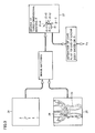
- Fig. 9 is a block diagram showing a load detection method according to Embodiment 4 of the present invention. According to this load detection method, load Fo at the tip end is detected while linear body 2 is being inserted. In Fig. 9 , linear body 2 is inserted in a human body while a doctor is observing a fluoroscopic two-dimensional image 24. In fluoroscopic two-dimensional image 24, a degree of three-dimensional bending of linear body 2 cannot be seen.
- a degree of three-dimensional bending of linear body 2 can be estimated. Since linear body 2 has been inserted in blood vessel 23 and in addition a path 26 from an insertion port to a destination (cerebral aneurysm 7) has been known, a position of linear body 2 in three-dimensional blood vessel image 25 can be known by matching fluoroscopic two-dimensional image 24 and three-dimensional blood vessel image 25 with each other. Thus, by using a degree of three-dimensional bending of blood vessel 23, degree of three-dimensional bending ⁇ of linear body 2 can be known. Therefore, even during insertion of linear body 2 in a human body, load Fo at the tip end of linear body 2 can be estimated.
- Fig. 10 is a block diagram showing a structure of an insertion load detection device included in a load detection device according to Embodiment 5 of the present invention.
- the insertion load detection device includes a pressing roller 30, a drive roller 31, a motor 32, and a torque control circuit 33.
- An outer circumferential portion of each of rollers 30 and 31 is formed of such an elastic body as rubber. Pressing roller 30 is rotatably supported and pressed toward drive roller 31 with a prescribed pressure. Therefore, pressing roller 30 is driven together with drive roller 31.
- Linear body 2 such as delivery wire 5 is inserted in hollow tube 1 as it passes between rollers 30 and 31.
- Drive roller 31 is rotatably driven by motor 32.
- Torque control circuit 33 supplies a drive current to motor 32 in accordance with a torque command value and outputs a signal indicating a drive current value to arithmetic processing unit 15 in Fig. 6 , instead of insertion load Fi.
- Arithmetic processing unit 15 in Fig. 6 calculates load Fi in insertion of linear body 2 based on a signal from torque control circuit 33 and finds load Fo at the tip end by using that insertion load Fi.
- load Fi in insertion of linear body 2 can readily be detected.
- Fig. 11 is a block diagram showing a structure of an insertion load detection device included in a load detection device according to Embodiment 6 of the present invention, and it is compared with Fig. 10 .
- the insertion load detection device in Fig. 11 is different from the insertion load detection device in Embodiment 5 in that a torque sensor 34 is provided between a rotation shaft of motor 32 and a rotation shaft of drive roller 31.
- a strain gauge or a magnetostrictive torque sensor is employed as torque sensor 34.
- Torque sensor 34 detects strain of a shaft coupling the rotation shaft of motor 32 and the rotation shaft of drive roller 31 to each other and outputs a signal indicating the detected value to arithmetic processing unit 15 in Fig. 6 , instead of insertion load Fi.
- Arithmetic processing unit 15 in Fig. 6 calculates load Fi in insertion of linear body 2 based on a signal from torque sensor 34 and finds load Fo at the tip end by using that insertion load Fi.
- load Fi in insertion of linear body 2 can readily be detected.
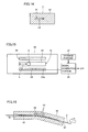
- Fig. 12 is a diagram showing appearance of a main portion of an insertion load detection device according to Embodiment 7 of the present invention
- Fig. 13 is a cross-sectional view along the line XIII-XIII in Fig. 12
- Fig. 14 is a cross-sectional view along the line XIV-XIV in Fig. 12
- the insertion load detection device includes a main body portion 40, and a through hole 41 through which linear body 2 passes is formed in main body portion 40.
- One end of linear body 2 is operated with a hand of an operator and the other end of linear body 2 is inserted in hollow tube 1 inserted in a vessel of a human body.
- a tapered input and output port 42 is formed at each of opening portions at respective opposing ends of through hole 41, for facilitating insertion and extraction of linear body 2.
- a diameter of through hole 41 is slightly greater than a diameter of linear body 2, and it is set, for example, to 105% to 120% of the diameter of linear body 2. Therefore, in restraint portion 43, linear body 2 cannot move in a direction other than a direction of longitudinal axis.
- main body portion 40 defines a direction of curve of linear body 2 within through hole 41. Namely, through hole 41 is bent between two restraint portions 43 and linear body 2 passes through through hole 41 while bending along one wall. In addition, through hole 41 forms a space 44 between two restraint portions 43, that extends toward a wall along which linear body 2 does not extend. Therefore, in space 44, an operation of linear body 2 in a direction in parallel to the sheet surface is not restricted by through hole 41.
- a height of through hole 41 in a direction perpendicular to the sheet surface is slightly greater than a diameter of linear body 2, and it is set, for example, to 105% to 120% of the diameter of linear body 2. Therefore, an operation of linear body 2 in the direction perpendicular to the sheet surface is restricted by through hole 41.
- a cross-sectional shape of through hole 3 in a cross-section perpendicular to the direction of longitudinal axis of linear body 2 is rectangular as shown in Fig. 14 .
- the direction of curve of linear body 2 within through hole 41 is thus defined and a position where linear body 2 curves at the time when insertion load Fi in the direction of longitudinal axis is applied to linear body 2 is determined.
- linear body 2 when insertion load Fi in the direction of longitudinal axis is applied to linear body 2, linear body 2 curves in a prescribed direction in space 44 inside through hole 41, that is, toward the wall along which linear body 2 does not extend in space 44. As linear body 2 curves, a height h of peak of curve, that is, a distance from a wall surface along which linear body 2 extends to linear body 2 increases. In main body portion 40, an optical line sensor 45 for detecting height h of the peak of curve is embedded.
- line sensor 45 is an array sensor having a plurality of light-receiving elements 45a aligned in a direction of height h of curve of linear body 2.
- a light source device 46 is embedded in main body 10 on the side opposite to line sensor 45, with space 44 in through hole 41 being interposed. Light source device 46 emits illumination light toward line sensor 45 through space 44.
- the illumination light emitted from light source device 46 is incident on line sensor 45 where linear body 2 is absent, however, it is cut off by linear body 2 where linear body 2 is present and is not incident on line sensor 45. In other words, a shadow of linear body 2 is cast on line sensor 45.
- a large photocurrent is generated in light-receiving element 45a that receives the illumination light, but a photocurrent is hardly generated in light-receiving element 45a located in the shadow of linear body 2. Therefore, by detecting a photocurrent of each light-receiving element 45a, a position of linear body 2 within space 44, that is, height h of curve of linear body 2, can be found.
- the insertion load detection device further includes a storage portion 47 and a signal generation portion 48.
- Storage portion 47 stores a table showing correlation between height h of curve of linear body 2 and insertion load Fi.
- Signal generation portion 48 finds height h of curve of linear body 2 by detecting a photocurrent of each light-receiving element 45a, finds insertion load Fi corresponding to that height h by referring to the table in storage portion 47, and outputs a signal ⁇ Fi indicating that insertion load Fi to arithmetic processing unit 15 in Fig. 6 .
- Arithmetic processing unit 15 in Fig. 6 finds load Fo at the tip end based on signal ⁇ Fi from signal generation portion 48.
- load Fi in insertion of linear body 2 can readily be detected.
- Fig. 16 is a cross-sectional view showing a main portion of an insertion load detection device according to Embodiment 8 of the present invention, and it is compared with Fig. 13 .
- the insertion load detection device includes a main body portion 50, and a through hole 51 through which linear body 2 passes is formed in main body portion 50.
- One end of linear body 2 is operated with a hand of an operator and the other end of linear body 2 is inserted in hollow tube 1 inserted in a vessel of a human body.
- a tapered input and output port 52 is formed at each of opening portions at respective opposing ends of through hole 51, for facilitating insertion and extraction of linear body 2.
- a diameter of through hole 51 is slightly greater than a diameter of linear body 2, and it is set, for example, to 105% to 120% of the diameter of linear body 2.
- Through hole 51 is bent in an arc shape in a central portion in a direction of length, and linear body 2 passes through through hole 51 while it is bent.
- An elastic member 53 is embedded on an outer side (an upper side in Fig. 16 ) of an arc-shaped portion in the central portion of through hole 51 and a strain sensor 54 is provided within elastic member 53.
- Linear body 2 is inserted in through hole 51 as it is bent. Therefore, when insertion load Fi is applied to linear body 2, a central portion curved in an arc-shape tends to further bend and a pressure is applied to strain sensor 54 through elastic member 53. Therefore, load Fi in insertion of linear body 2 can be detected based on an output signal from strain sensor 54. Arithmetic processing unit 15 in Fig. 6 finds insertion load Fi from strain sensor 54 and finds load Fo at the tip end based on that insertion load Fi.
- load Fi in insertion of linear body 2 can readily be detected.
- Fig. 17 is a block diagram showing a structure of medical equipment according to Embodiment 9 of the present invention.
- the tip end of catheter 3 is inserted in an artery at the base of the leg of a human body 55 and guided, for example, to a mouth of cerebral aneurysm 7.
- the base end of catheter 3 is connected to outlet 8a of Y-connector 8.
- An insertion load detection device 56 is attached to one inlet 8b of Y-connector 8 and physiological saline is injected into catheter 3 through another inlet 8c.
- the device shown in Embodiments 7 and 8 is used as insertion load detection device 56.
- Insertion load detection device 56 and Y-connector 8 may integrally be formed.
- Linear body 2 is inserted in catheter 3 through insertion load detection device 56 and Y-connector 8. A degree of bending of linear body 2 is found, for example, with the method shown in Embodiments 3 and 4.
- An output signal from insertion load detection device 56 is provided to an operation device 58 through a cable 57.
- a display 59, a speaker 60 and a switch 61 are connected to operation device 58.
- Operation device 58 finds load Fo at the tip end of linear body 2 based on the output signal from insertion load detection device 56, a degree of bending of linear body 2, and the like.
- Display 59 provides visual display of load Fo at the tip end or insertion load Fi by using numerics.
- Speaker 60 gives aural notification of load Fo at the tip end or insertion load Fi by using tone, volume or the like.
- Switch 61 switches between display 59 and speaker 60, for providing display or giving notification of any of load Fo at the tip end and insertion load Fi.
- a doctor can know load Fo at the tip end or insertion load Fi by viewing display on display 59 or listening to sound from speaker 60, and operates linear body 2 based thereon.
- Fig. 18 is a block diagram showing a structure of medical training equipment according to Embodiment 9 of the present invention, and it is compared with Fig. 17 .
- a simulator 62 is used instead of human body 55.
- Simulator 62 causes a monitor 63 to display a simulated perspective image equivalent to a fluoroscopic image of a vessel in a human body in which linear body 2 is inserted.
- Linear body 2 is, for example, embolization coil 4 and delivery wire 5 inserted in catheter 3 of which tip end is disposed at the mouth of cerebral aneurysm 7.
- Simulator 62 varies insertion resistance of inserted linear body 2. Resistance force at the time of operation, that is, load Fi in insertion of linear body 2, is transmitted also to simulator 62 through a cable 64.
- Simulator 62 varies insertion resistance of linear body 2 in accordance with insertion load Fi.
- An operator in training operates linear body 2 while viewing a simulated perspective image displayed on monitor 63 and insertion load Fi or load Fo at the tip end displayed on display 59 and further listening to sound from speaker 60 indicating insertion load Fi or load Fo at the tip end.
- the simulated perspective image, insertion load Fi and load Fo at the tip end during operation are recorded in a video image recording medium within a video image recording apparatus (not shown). The record is utilized for training or evaluation of an operator.
- the video image recording medium records a simulated perspective image, insertion load Fi, load Fo at the tip end, and a commentary by a person of skill at the time when he/she operates linear body 2 in simulator 62. A less experienced operator can reproduce the operation records of the person of skill and learn his/her manipulation.
- manipulation of a skilled operator can be quantified and transferred to a less experienced operator, so that manipulation of the less experienced operator can quickly be improved.
Landscapes
- Health & Medical Sciences (AREA)
- Life Sciences & Earth Sciences (AREA)
- Surgery (AREA)
- General Health & Medical Sciences (AREA)
- Veterinary Medicine (AREA)
- Public Health (AREA)
- Engineering & Computer Science (AREA)
- Biomedical Technology (AREA)
- Heart & Thoracic Surgery (AREA)
- Medical Informatics (AREA)
- Molecular Biology (AREA)
- Animal Behavior & Ethology (AREA)
- Nuclear Medicine, Radiotherapy & Molecular Imaging (AREA)
- Vascular Medicine (AREA)
- Reproductive Health (AREA)
- Pathology (AREA)
- Physics & Mathematics (AREA)
- Neurosurgery (AREA)
- Oral & Maxillofacial Surgery (AREA)
- Biophysics (AREA)
- Media Introduction/Drainage Providing Device (AREA)
- Surgical Instruments (AREA)
- Force Measurement Appropriate To Specific Purposes (AREA)
- Measuring And Recording Apparatus For Diagnosis (AREA)
- Measurement Of The Respiration, Hearing Ability, Form, And Blood Characteristics Of Living Organisms (AREA)
- Investigating Strength Of Materials By Application Of Mechanical Stress (AREA)
Claims (17)
- Eine Belastungsdetektionsvorrichtung zum Ermitteln von Belastung die auf ein äußeres Ende bzw. Spitzen-Ende eines linearen Körpers (2) ausgeübt wird, der Flexibilität aufweist, wenn der lineare Körper (2) in ein hohles Rohr (1) eingesetzt bzw. eingeführt wird, das in ein gebogenes Gefäß (23) eingesetzt wird, umfassend:ein erstes Detektionsmittel (12) zum Ermitteln eines Biegegrads des Gefäßes (23), des hohlen Rohres (1) oder des linearen Körpers (2);ein zweites Detektionsmittel (13) zum Ermitteln von Belastung beim Einsetzen des linearen Körpers (2) in einen Eingang des hohlen Rohres (1); undein Berechnungsmittel (15) zur Feststellung von Belastung die auf das äußere Ende des linearen Körpers (2) ausgeübt wird, basierend auf einem Detektionsergebnis durch das erste und zweite Detektionsmittel (12, 13)dadurch gekennzeichnet, dassdas Berechnungsmittel (15) die Belastung, die auf das äußere Ende des linearen Körpers (2) ausgebübt wird, feststellt, des Weiteren basierend auf einem Reibungskoeffizienten zwischen dem linearen Körper (2) und dem hohlen Rohr (1).
- Belastungsdetektionsvorrichtung nach Anspruch 1, wobei
das erste Detektionsmittel (12) den Biegegrad des Gefäßes (23), des hohlen Rohres (1) oder des linearen Körpers (2) ermittelt, basierend auf einer Abbildung des Gefäßes (23), des hohlen Rohres (1) oder des linearen Körpers (2). - Belastungsdetektionsvorrichtung nach Anspruch 1, wobei
das Berechnungsmittel (15) den Reibungskoeffizient basierend auf einer Variation der Biegesteifigkeit in Abhängigkeit einer Position im linearen Körper (2) korrigiert, wenn die Biegesteifigkeit des linearen Körpers (2) in Abhängigkeit der Position in dem linearen Körper (2) variiert. - Belastungsdetektionsvorrichtung nach Anspruch 1, wobei
der Reibungskoeffizient im Voraus gemessen wird. - Belastungsdetektionsvorrichtung nach Anspruch 1 geeignet zum Einsetzen in
ein Blutgefäß (23),
wobei das hohle Rohr (1) ein Katheter (3) ist, und
der lineare Körper (2) ein Behandlungsdraht (4, 5) zum Einsetzen in den Katheter (3) ist. - Belastungsdetektionsvorrichtung nach Anspruch 5, wobei
der Behandlungsdraht (4, 5) einen Führungsdraht (5) und eine Embolisationsspirale bzw. - spule (4) beinhaltet, die an einem äußeren Ende des Führungsdrahtes (5) vorgesehen sind, um ein zerebrales Aneurysma (7) zu füllen. - Belastungsdetektionsvorrichtung nach Anspruch 6, wobei
das erste Detektionsmittel (12) einen Biegegrad des Behandlungsdrahtes (4, 5) ermittelt, wenn ein äußeres Ende der Embolisationsspirale (4) in das zerebrale Aneurysma (7) eintritt, und
das Berechnungsmittel (15) Belastung durch die Embolisationsspirale auf das zerebrale Aneurysma (7) feststellt. - Belastungsdetektionsvorrichtung nach Anspruch 5, wobei
das erste Detektionsmittel (12) einen Biegegrad des Blutgefäßes (23) basierend auf einer dreidimensionalen Abbildung des Blutgefäßes (23) ermittelt. - Belastungsdetektionsvorrichtung nach Anspruch 5, wobei
das erste Detektionsmittel (12) einen Biegegrad des Behandlungsdrahtes (4, 5) basierend auf einer zweidimensionalen Abbildung des Behandlungsdrahtes (4, 5) ermittelt, die erstellt wird mittels Röntgenstrahlen während einer chirurgischen Operation und einer im Voraus erstellten dreidimensionalen Abbildung des Blutgefäßes (23), wie sie übereinander gelagert sind. - Belastungsdetektionsvorrichtung nach Anspruch 1, umfassend Antriebsmittel (30 bis 32) zum Einsetzen des linearen Körpers (2) in den Eingang des hohlen Rohres (1), wobei
das zweite Detektionsmittel (33, 15) die Belastung beim Einsetzen des linearen Körpers (2) ermittelt, basierend auf der Antriebskraft des Antriebsmittels (30 bis 32). - Belastungsdetektionsvorrichtung nach Anspruch 1, umfassend:eine Antriebswalze (31) zum Einsetzen des linearen Körper (2) in den Eingang des hohlen Rohres (1);eine Anpresswalze (30), die drehbar gelagert und durch die Antriebswalze (31) gepresst wird, wobei der lineare Körper (2) dazwischengelagert ist; undeinen Motor (32) zum drehbaren Antreiben der Antriebswalze (31), wobeidas zweite Detektionsmittel (34, 15) den Druck einer Rotationswelle des Motors (32) ermittelt und die Belastung beim Einsetzen des linearen Körpers (2) ermittelt, basierend auf einem Ergebnis dieser Ermittelung.
- Belastungsdetektionsvorrichtung nach Anspruch 1, wobei
das zweite Detektionsmittel (40, 47, 48) beinhaltet:einen Hauptkörperabschnitt (40) mit einer Bohrung (41) durch welche der lineare Körper (2) hindurchtritt, und einen Innenraum (44) an einem Zwischenpunkt der Bohrung (41), so ausgebildet, dass der lineare Körper (2) sich in eine vorgegebene Richtung biegen kann, wenn eine Kompressionskraft auf den linearen Körper (2) ausgeübt wird, undeinen Biegungssensor (45, 46) zum Ermitteln eines Biegungsgrades des linearen Körpers (2) im Innenraum (44), undwobei das zweite Detektionsmittel die Belastung beim Einsetzen des linearen Körpers (2) ermittelt basierend auf dem Biegungsgrad, der durch den Biegungssensor (45, 46) ermittelt wird. - Belastungsdetektionsvorrichtung nach Anspruch 1, wobei
das zweite Detektionsmittel (50, 54) beinhaltet:einen Hauptkörperabschnitt (50) mit einer Bohrung (51) durch welche der lineare Körper (2) hindurchtritt und mit einer Biegung geformt, so dass der lineare Körper (2) in einer vorgeschriebenen Richtung Druck ausübt, wenn eine Kompressionskraft auf den linearen Körper (2) ausgeübt wird, undeinen Drucksensor (54), der an einem Zwischenpunkt der Bohrung (51) vorgesehen ist, zum Ermitteln eines Drucks der durch den linearen Körper (2) in der vorgegebenen Richtung ausgeübt wird, undwobei das zweite Detektionsmittel die Belastung bei Einsetzung des linearen Körpers (2) ermittelt basierend auf einem Detektionsergebnis durch den Drucksensor (54). - Belastungsdetektionsvorrichtung nach Anspruch 1, des Weiteren umfassend ein Anzeigemittel (59) zur visuellen Anzeige von mindestens einer Belastung der Belastung beim Einsetzen des linearen Körpers (2), die durch das zweite Detektionsmittel (56) ermittelt wurde, und der Belastung, die auf das äußere Ende des linearen Körpers (2) ausgeübt wird und durch das Berechnungsmittel (58) festgestellt wird.
- Belastungsdetektionsvorrichtung nach Anspruch 1, des Weiteren umfassend ein Tonerzeugungsmittel (60) zum Erzeugen von Ton zum Anzeigen von mindestens einer Belastung der Belastung bei Einsetzung des linearen Körpers (2), die durch das zweite Detektionsmittel (56) ermittelt wurde, und der Belastung, die auf das äußere Ende des linearen Körpers (2) ausgeübt wird und durch das Berechnungsmittel (58) festgestellt wird.
- Belastungsdetektionsvorrichtung nach Anspruch 1, des Weiteren umfassend
Aufnahmemittel zum Aufnehmen in einem Videobildaufnahmemedium zusammen mit einem fluoroskopischen Bild eines Spitzenendabschnitts des linearen Körpers, mindestens einer Belastung der Belastung beim Einsetzen des linearen Körpers (2), die durch das zweite Detektionsmittel (56) ermittelt wurde, und der Belastung, die auf das äußere Ende des linearen Körpers (2) ausgeübt wird und durch das Berechnungsmittel (58) festgestellt wird. - Belastungsdetektionsvorrichtung nach einem der Ansprüche 1 bis 16, geeignet, um in einen medizinischen Übungsapparat eingebaut zu werden.
Applications Claiming Priority (3)
| Application Number | Priority Date | Filing Date | Title |
|---|---|---|---|
| JP2007323670 | 2007-12-14 | ||
| JP2008266365A JP5171535B2 (ja) | 2007-12-14 | 2008-10-15 | 荷重検出装置および荷重検出方法 |
| PCT/JP2008/072030 WO2009078280A1 (ja) | 2007-12-14 | 2008-12-04 | 荷重検出装置および荷重検出方法 |
Publications (3)
| Publication Number | Publication Date |
|---|---|
| EP2233902A1 EP2233902A1 (de) | 2010-09-29 |
| EP2233902A4 EP2233902A4 (de) | 2011-12-14 |
| EP2233902B1 true EP2233902B1 (de) | 2013-10-09 |
Family
ID=40795398
Family Applications (1)
| Application Number | Title | Priority Date | Filing Date |
|---|---|---|---|
| EP08861483.9A Not-in-force EP2233902B1 (de) | 2007-12-14 | 2008-12-04 | Belastungsdetektor |
Country Status (4)
| Country | Link |
|---|---|
| US (1) | US8725233B2 (de) |
| EP (1) | EP2233902B1 (de) |
| JP (1) | JP5171535B2 (de) |
| WO (1) | WO2009078280A1 (de) |
Families Citing this family (42)
| Publication number | Priority date | Publication date | Assignee | Title |
|---|---|---|---|---|
| US8357152B2 (en) | 2007-10-08 | 2013-01-22 | Biosense Webster (Israel), Ltd. | Catheter with pressure sensing |
| US8535308B2 (en) | 2007-10-08 | 2013-09-17 | Biosense Webster (Israel), Ltd. | High-sensitivity pressure-sensing probe |
| US8437832B2 (en) | 2008-06-06 | 2013-05-07 | Biosense Webster, Inc. | Catheter with bendable tip |
| US9101734B2 (en) | 2008-09-09 | 2015-08-11 | Biosense Webster, Inc. | Force-sensing catheter with bonded center strut |
| US9326700B2 (en) | 2008-12-23 | 2016-05-03 | Biosense Webster (Israel) Ltd. | Catheter display showing tip angle and pressure |
| US8600472B2 (en) | 2008-12-30 | 2013-12-03 | Biosense Webster (Israel), Ltd. | Dual-purpose lasso catheter with irrigation using circumferentially arranged ring bump electrodes |
| US8475450B2 (en) | 2008-12-30 | 2013-07-02 | Biosense Webster, Inc. | Dual-purpose lasso catheter with irrigation |
| GB0902339D0 (en) * | 2009-02-12 | 2009-04-01 | St Georges Healthcare Nhs Trus | Percutaneous guidewire |
| WO2011046028A1 (ja) * | 2009-10-14 | 2011-04-21 | 国立大学法人 名古屋工業大学 | 挿入装置、訓練装置および記録システム |
| US10688278B2 (en) | 2009-11-30 | 2020-06-23 | Biosense Webster (Israel), Ltd. | Catheter with pressure measuring tip |
| US8521462B2 (en) | 2009-12-23 | 2013-08-27 | Biosense Webster (Israel), Ltd. | Calibration system for a pressure-sensitive catheter |
| US8529476B2 (en) | 2009-12-28 | 2013-09-10 | Biosense Webster (Israel), Ltd. | Catheter with strain gauge sensor |
| US8374670B2 (en) * | 2010-01-22 | 2013-02-12 | Biosense Webster, Inc. | Catheter having a force sensing distal tip |
| US8798952B2 (en) | 2010-06-10 | 2014-08-05 | Biosense Webster (Israel) Ltd. | Weight-based calibration system for a pressure sensitive catheter |
| US8226580B2 (en) | 2010-06-30 | 2012-07-24 | Biosense Webster (Israel), Ltd. | Pressure sensing for a multi-arm catheter |
| US8731859B2 (en) | 2010-10-07 | 2014-05-20 | Biosense Webster (Israel) Ltd. | Calibration system for a force-sensing catheter |
| US8979772B2 (en) | 2010-11-03 | 2015-03-17 | Biosense Webster (Israel), Ltd. | Zero-drift detection and correction in contact force measurements |
| EP2663239B1 (de) * | 2011-01-13 | 2015-08-26 | Koninklijke Philips N.V. | Ablösungswerkzeug zur abkopplung eines formsensors von einer implantierbaren vorrichtung |
| US9220433B2 (en) | 2011-06-30 | 2015-12-29 | Biosense Webster (Israel), Ltd. | Catheter with variable arcuate distal section |
| US9662169B2 (en) | 2011-07-30 | 2017-05-30 | Biosense Webster (Israel) Ltd. | Catheter with flow balancing valve |
| US9687289B2 (en) | 2012-01-04 | 2017-06-27 | Biosense Webster (Israel) Ltd. | Contact assessment based on phase measurement |
| CN103648395B (zh) * | 2012-06-07 | 2017-07-28 | 松下知识产权经营株式会社 | 转矩测定装置 |
| JP6064263B2 (ja) * | 2012-07-10 | 2017-01-25 | パナソニックIpマネジメント株式会社 | 力計測装置及び力計測方法、マスタースレーブ装置、力計測プログラム、並びに、集積電子回路 |
| JP6172630B2 (ja) | 2012-10-09 | 2017-08-02 | パナソニックIpマネジメント株式会社 | 力呈示装置 |
| WO2014105578A1 (en) * | 2012-12-27 | 2014-07-03 | Volcano Corporation | Intravascular guidewire with hyper flexible distal end portion |
| KR101582737B1 (ko) * | 2014-03-28 | 2016-01-06 | 가톨릭대학교 산학협력단 | 안구 수술 연습용 기기 |
| JP6586955B2 (ja) * | 2014-08-26 | 2019-10-09 | 国立大学法人 名古屋工業大学 | 接触検出器具 |
| WO2017004483A1 (en) * | 2015-07-02 | 2017-01-05 | Mirus Llc | Medical devices with integrated sensors and method of production |
| WO2017010231A1 (ja) * | 2015-07-16 | 2017-01-19 | 国立大学法人名古屋大学 | 線状体の挿入駆動装置およびそれを備える医療機器、医療操作訓練装置 |
| US20180207396A1 (en) * | 2015-08-05 | 2018-07-26 | Koninklijke Philips N.V. | Catheter assembly with low axial sliding friction |
| KR101771995B1 (ko) | 2015-12-15 | 2017-08-28 | 한전케이피에스 주식회사 | 블레이드 검사용 와전류 프로브 장치 |
| WO2017136548A1 (en) | 2016-02-04 | 2017-08-10 | Cardiac Pacemakers, Inc. | Delivery system with force sensor for leadless cardiac device |
| WO2017221298A1 (ja) * | 2016-06-20 | 2017-12-28 | オリンパス株式会社 | 可撓管挿入装置 |
| WO2018135041A1 (ja) * | 2017-01-17 | 2018-07-26 | オリンパス株式会社 | 内視鏡挿入形状観測装置 |
| US11248973B2 (en) * | 2017-02-16 | 2022-02-15 | C. R. Bard, Inc. | Insertion and withdrawal force measurement system |
| WO2018203365A1 (ja) | 2017-05-01 | 2018-11-08 | オリンパス株式会社 | 医療用マニピュレータシステム及び医療用マニピュレータシステムの作動方法 |
| US10219716B2 (en) | 2017-06-01 | 2019-03-05 | Biosense Webster (Israel) Ltd. | Using a piecewise-linear model of a catheter arm to identify contact with tissue |
| JP7110351B2 (ja) * | 2018-08-01 | 2022-08-01 | オリンパス株式会社 | 内視鏡システム及び制御装置 |
| KR102105248B1 (ko) * | 2018-08-23 | 2020-05-29 | 부산대학교병원 | 비선형 변형해석을 이용한 다분절 카테터의 굽힘 변형 및 강성 측정방법 및 이를 이용한 카테터의 굽힘 변형 및 강성 측정장치 |
| US12246142B2 (en) * | 2019-04-29 | 2025-03-11 | Siemens Healthineers Endovascular Robotics, Inc. | Load sensing system for percutaneous device with a curved path |
| CN110215239B (zh) * | 2019-05-05 | 2021-02-26 | 清华大学 | 融合图像和力信号的介入手术器具载荷识别装置及方法 |
| CN114587616B (zh) * | 2022-02-23 | 2023-04-25 | 上海奥朋医疗科技有限公司 | 导丝导管输送装置 |
Family Cites Families (11)
| Publication number | Priority date | Publication date | Assignee | Title |
|---|---|---|---|---|
| US6117157A (en) * | 1994-03-18 | 2000-09-12 | Cook Incorporated | Helical embolization coil |
| JPH10263089A (ja) * | 1997-03-27 | 1998-10-06 | Tokai Rika Co Ltd | 障害物感知機構付きカテーテル |
| US7309519B2 (en) * | 1998-10-05 | 2007-12-18 | 3M Innovative Properties Company | Friction control articles for healthcare applications |
| DE19963440C2 (de) * | 1999-12-28 | 2003-02-20 | Siemens Ag | Verfahren und System zur Visualisierung eines Gegenstandes |
| US6817973B2 (en) * | 2000-03-16 | 2004-11-16 | Immersion Medical, Inc. | Apparatus for controlling force for manipulation of medical instruments |
| EP1805744A2 (de) * | 2004-08-10 | 2007-07-11 | The General Hospital Corporation | Verfahren und vorrichtungen zur simulation von endovaskulären und endoluminalen prozeduren |
| US8182433B2 (en) * | 2005-03-04 | 2012-05-22 | Endosense Sa | Medical apparatus system having optical fiber load sensing capability |
| US8192374B2 (en) * | 2005-07-18 | 2012-06-05 | Stereotaxis, Inc. | Estimation of contact force by a medical device |
| JP4878513B2 (ja) * | 2006-03-27 | 2012-02-15 | 国立大学法人 名古屋工業大学 | 可撓性線状体の圧縮力計測装置および方法 |
| US7961924B2 (en) * | 2006-08-21 | 2011-06-14 | Stereotaxis, Inc. | Method of three-dimensional device localization using single-plane imaging |
| JP5028682B2 (ja) * | 2007-01-26 | 2012-09-19 | 国立大学法人 名古屋工業大学 | 圧縮力計測装置 |
-
2008
- 2008-10-15 JP JP2008266365A patent/JP5171535B2/ja not_active Expired - Fee Related
- 2008-12-04 EP EP08861483.9A patent/EP2233902B1/de not_active Not-in-force
- 2008-12-04 WO PCT/JP2008/072030 patent/WO2009078280A1/ja not_active Ceased
- 2008-12-04 US US12/808,125 patent/US8725233B2/en not_active Expired - Fee Related
Also Published As
| Publication number | Publication date |
|---|---|
| US8725233B2 (en) | 2014-05-13 |
| EP2233902A1 (de) | 2010-09-29 |
| WO2009078280A1 (ja) | 2009-06-25 |
| JP2009162746A (ja) | 2009-07-23 |
| JP5171535B2 (ja) | 2013-03-27 |
| US20100292566A1 (en) | 2010-11-18 |
| EP2233902A4 (de) | 2011-12-14 |
Similar Documents
| Publication | Publication Date | Title |
|---|---|---|
| EP2233902B1 (de) | Belastungsdetektor | |
| US6981945B1 (en) | Colonoscope handgrip with force and torque monitor | |
| EP2135635B1 (de) | Vorrichtung zum antreiben eines linearen objekts | |
| JP6465452B2 (ja) | 内視鏡挿入形状観測装置 | |
| US20100234873A1 (en) | Drive device, and medical apparatus and training apparatus including the same | |
| JP5403785B2 (ja) | 挿入装置 | |
| EP2959820A1 (de) | Patienteneinsetzsystem | |
| US20110065991A1 (en) | Handgrip for assessment of colonoscope manipulation | |
| US20090177032A1 (en) | Method and apparatus for magnetically controlling endoscopes in body lumens and cavities | |
| US8388518B2 (en) | Simplified handgrip for assessment of colonoscope manipulation | |
| CN109561878B (zh) | 血管内过程中的位置感测 | |
| US20150313446A1 (en) | Robotic-assisted surgical system and control method thereof | |
| US8412311B2 (en) | Fluoroscopy-free guidewire systems and methods | |
| Dogramadzi et al. | Recording forces exerted on the bowel wall during colonoscopy: in vitro evaluation | |
| US20120174686A1 (en) | Measurement device, medical device, training device, and measurement method | |
| JP6751872B2 (ja) | 線状体の挿入駆動装置およびそれを備える医療機器、医療操作訓練装置 | |
| US20120022330A1 (en) | Tactile indicator for endoscopic instruments | |
| JP5190867B2 (ja) | 計測装置 | |
| Ikuta et al. | “Surgery recorder system” for recording position and force of forceps during laparoscopic surgery | |
| JP2007202675A (ja) | センサならびにそれを備えた医療装置および訓練装置 | |
| Chandler et al. | Evaluation of a novel, ultrathin, tip-bending endoscope in a synthetic force-sensing pancreas with comparison to medical guide wires | |
| Chandler et al. | Improving patient and user safety during endoscopic investigation of the pancreatic and biliary ducts | |
| JP2001145598A (ja) | 内視鏡の体内挿入部の彎曲検知方法及び装置 |
Legal Events
| Date | Code | Title | Description |
|---|---|---|---|
| PUAI | Public reference made under article 153(3) epc to a published international application that has entered the european phase |
Free format text: ORIGINAL CODE: 0009012 |
|
| 17P | Request for examination filed |
Effective date: 20100617 |
|
| AK | Designated contracting states |
Kind code of ref document: A1 Designated state(s): AT BE BG CH CY CZ DE DK EE ES FI FR GB GR HR HU IE IS IT LI LT LU LV MC MT NL NO PL PT RO SE SI SK TR |
|
| AX | Request for extension of the european patent |
Extension state: AL BA MK RS |
|
| DAX | Request for extension of the european patent (deleted) | ||
| A4 | Supplementary search report drawn up and despatched |
Effective date: 20111114 |
|
| RIC1 | Information provided on ipc code assigned before grant |
Ipc: A61B 17/00 20060101ALN20111108BHEP Ipc: A61B 19/00 20060101ALN20111108BHEP Ipc: A61B 17/12 20060101ALI20111108BHEP Ipc: A61M 25/00 20060101ALI20111108BHEP Ipc: G01L 5/00 20060101AFI20111108BHEP |
|
| GRAP | Despatch of communication of intention to grant a patent |
Free format text: ORIGINAL CODE: EPIDOSNIGR1 |
|
| INTG | Intention to grant announced |
Effective date: 20130424 |
|
| GRAS | Grant fee paid |
Free format text: ORIGINAL CODE: EPIDOSNIGR3 |
|
| GRAA | (expected) grant |
Free format text: ORIGINAL CODE: 0009210 |
|
| AK | Designated contracting states |
Kind code of ref document: B1 Designated state(s): AT BE BG CH CY CZ DE DK EE ES FI FR GB GR HR HU IE IS IT LI LT LU LV MC MT NL NO PL PT RO SE SI SK TR |
|
| REG | Reference to a national code |
Ref country code: GB Ref legal event code: FG4D |
|
| REG | Reference to a national code |
Ref country code: AT Ref legal event code: REF Ref document number: 635761 Country of ref document: AT Kind code of ref document: T Effective date: 20131015 Ref country code: CH Ref legal event code: EP |
|
| REG | Reference to a national code |
Ref country code: IE Ref legal event code: FG4D |
|
| REG | Reference to a national code |
Ref country code: DE Ref legal event code: R096 Ref document number: 602008028052 Country of ref document: DE Effective date: 20131205 |
|
| REG | Reference to a national code |
Ref country code: AT Ref legal event code: MK05 Ref document number: 635761 Country of ref document: AT Kind code of ref document: T Effective date: 20131009 |
|
| REG | Reference to a national code |
Ref country code: NL Ref legal event code: VDEP Effective date: 20131009 |
|
| PG25 | Lapsed in a contracting state [announced via postgrant information from national office to epo] |
Ref country code: SI Free format text: LAPSE BECAUSE OF FAILURE TO SUBMIT A TRANSLATION OF THE DESCRIPTION OR TO PAY THE FEE WITHIN THE PRESCRIBED TIME-LIMIT Effective date: 20131009 |
|
| REG | Reference to a national code |
Ref country code: LT Ref legal event code: MG4D |
|
| PG25 | Lapsed in a contracting state [announced via postgrant information from national office to epo] |
Ref country code: NO Free format text: LAPSE BECAUSE OF FAILURE TO SUBMIT A TRANSLATION OF THE DESCRIPTION OR TO PAY THE FEE WITHIN THE PRESCRIBED TIME-LIMIT Effective date: 20140109 Ref country code: BE Free format text: LAPSE BECAUSE OF FAILURE TO SUBMIT A TRANSLATION OF THE DESCRIPTION OR TO PAY THE FEE WITHIN THE PRESCRIBED TIME-LIMIT Effective date: 20131009 Ref country code: LT Free format text: LAPSE BECAUSE OF FAILURE TO SUBMIT A TRANSLATION OF THE DESCRIPTION OR TO PAY THE FEE WITHIN THE PRESCRIBED TIME-LIMIT Effective date: 20131009 Ref country code: IS Free format text: LAPSE BECAUSE OF FAILURE TO SUBMIT A TRANSLATION OF THE DESCRIPTION OR TO PAY THE FEE WITHIN THE PRESCRIBED TIME-LIMIT Effective date: 20140209 Ref country code: NL Free format text: LAPSE BECAUSE OF FAILURE TO SUBMIT A TRANSLATION OF THE DESCRIPTION OR TO PAY THE FEE WITHIN THE PRESCRIBED TIME-LIMIT Effective date: 20131009 Ref country code: SE Free format text: LAPSE BECAUSE OF FAILURE TO SUBMIT A TRANSLATION OF THE DESCRIPTION OR TO PAY THE FEE WITHIN THE PRESCRIBED TIME-LIMIT Effective date: 20131009 Ref country code: HR Free format text: LAPSE BECAUSE OF FAILURE TO SUBMIT A TRANSLATION OF THE DESCRIPTION OR TO PAY THE FEE WITHIN THE PRESCRIBED TIME-LIMIT Effective date: 20131009 Ref country code: FI Free format text: LAPSE BECAUSE OF FAILURE TO SUBMIT A TRANSLATION OF THE DESCRIPTION OR TO PAY THE FEE WITHIN THE PRESCRIBED TIME-LIMIT Effective date: 20131009 |
|
| PG25 | Lapsed in a contracting state [announced via postgrant information from national office to epo] |
Ref country code: CY Free format text: LAPSE BECAUSE OF FAILURE TO SUBMIT A TRANSLATION OF THE DESCRIPTION OR TO PAY THE FEE WITHIN THE PRESCRIBED TIME-LIMIT Effective date: 20131009 Ref country code: AT Free format text: LAPSE BECAUSE OF FAILURE TO SUBMIT A TRANSLATION OF THE DESCRIPTION OR TO PAY THE FEE WITHIN THE PRESCRIBED TIME-LIMIT Effective date: 20131009 Ref country code: PL Free format text: LAPSE BECAUSE OF FAILURE TO SUBMIT A TRANSLATION OF THE DESCRIPTION OR TO PAY THE FEE WITHIN THE PRESCRIBED TIME-LIMIT Effective date: 20131009 Ref country code: LV Free format text: LAPSE BECAUSE OF FAILURE TO SUBMIT A TRANSLATION OF THE DESCRIPTION OR TO PAY THE FEE WITHIN THE PRESCRIBED TIME-LIMIT Effective date: 20131009 Ref country code: ES Free format text: LAPSE BECAUSE OF FAILURE TO SUBMIT A TRANSLATION OF THE DESCRIPTION OR TO PAY THE FEE WITHIN THE PRESCRIBED TIME-LIMIT Effective date: 20131009 |
|
| PG25 | Lapsed in a contracting state [announced via postgrant information from national office to epo] |
Ref country code: PT Free format text: LAPSE BECAUSE OF FAILURE TO SUBMIT A TRANSLATION OF THE DESCRIPTION OR TO PAY THE FEE WITHIN THE PRESCRIBED TIME-LIMIT Effective date: 20140210 |
|
| REG | Reference to a national code |
Ref country code: DE Ref legal event code: R097 Ref document number: 602008028052 Country of ref document: DE |
|
| PG25 | Lapsed in a contracting state [announced via postgrant information from national office to epo] |
Ref country code: EE Free format text: LAPSE BECAUSE OF FAILURE TO SUBMIT A TRANSLATION OF THE DESCRIPTION OR TO PAY THE FEE WITHIN THE PRESCRIBED TIME-LIMIT Effective date: 20131009 |
|
| REG | Reference to a national code |
Ref country code: CH Ref legal event code: PL |
|
| PLBE | No opposition filed within time limit |
Free format text: ORIGINAL CODE: 0009261 |
|
| STAA | Information on the status of an ep patent application or granted ep patent |
Free format text: STATUS: NO OPPOSITION FILED WITHIN TIME LIMIT |
|
| PG25 | Lapsed in a contracting state [announced via postgrant information from national office to epo] |
Ref country code: CZ Free format text: LAPSE BECAUSE OF FAILURE TO SUBMIT A TRANSLATION OF THE DESCRIPTION OR TO PAY THE FEE WITHIN THE PRESCRIBED TIME-LIMIT Effective date: 20131009 Ref country code: IT Free format text: LAPSE BECAUSE OF FAILURE TO SUBMIT A TRANSLATION OF THE DESCRIPTION OR TO PAY THE FEE WITHIN THE PRESCRIBED TIME-LIMIT Effective date: 20131009 Ref country code: SK Free format text: LAPSE BECAUSE OF FAILURE TO SUBMIT A TRANSLATION OF THE DESCRIPTION OR TO PAY THE FEE WITHIN THE PRESCRIBED TIME-LIMIT Effective date: 20131009 Ref country code: RO Free format text: LAPSE BECAUSE OF FAILURE TO SUBMIT A TRANSLATION OF THE DESCRIPTION OR TO PAY THE FEE WITHIN THE PRESCRIBED TIME-LIMIT Effective date: 20131009 Ref country code: LU Free format text: LAPSE BECAUSE OF FAILURE TO SUBMIT A TRANSLATION OF THE DESCRIPTION OR TO PAY THE FEE WITHIN THE PRESCRIBED TIME-LIMIT Effective date: 20131204 Ref country code: MC Free format text: LAPSE BECAUSE OF FAILURE TO SUBMIT A TRANSLATION OF THE DESCRIPTION OR TO PAY THE FEE WITHIN THE PRESCRIBED TIME-LIMIT Effective date: 20131009 |
|
| 26N | No opposition filed |
Effective date: 20140710 |
|
| REG | Reference to a national code |
Ref country code: IE Ref legal event code: MM4A |
|
| PG25 | Lapsed in a contracting state [announced via postgrant information from national office to epo] |
Ref country code: DK Free format text: LAPSE BECAUSE OF FAILURE TO SUBMIT A TRANSLATION OF THE DESCRIPTION OR TO PAY THE FEE WITHIN THE PRESCRIBED TIME-LIMIT Effective date: 20131009 |
|
| REG | Reference to a national code |
Ref country code: DE Ref legal event code: R097 Ref document number: 602008028052 Country of ref document: DE Effective date: 20140710 |
|
| PG25 | Lapsed in a contracting state [announced via postgrant information from national office to epo] |
Ref country code: IE Free format text: LAPSE BECAUSE OF NON-PAYMENT OF DUE FEES Effective date: 20131204 Ref country code: CH Free format text: LAPSE BECAUSE OF NON-PAYMENT OF DUE FEES Effective date: 20131231 Ref country code: LI Free format text: LAPSE BECAUSE OF NON-PAYMENT OF DUE FEES Effective date: 20131231 |
|
| PG25 | Lapsed in a contracting state [announced via postgrant information from national office to epo] |
Ref country code: TR Free format text: LAPSE BECAUSE OF FAILURE TO SUBMIT A TRANSLATION OF THE DESCRIPTION OR TO PAY THE FEE WITHIN THE PRESCRIBED TIME-LIMIT Effective date: 20131009 |
|
| PG25 | Lapsed in a contracting state [announced via postgrant information from national office to epo] |
Ref country code: HU Free format text: LAPSE BECAUSE OF FAILURE TO SUBMIT A TRANSLATION OF THE DESCRIPTION OR TO PAY THE FEE WITHIN THE PRESCRIBED TIME-LIMIT; INVALID AB INITIO Effective date: 20081204 Ref country code: BG Free format text: LAPSE BECAUSE OF FAILURE TO SUBMIT A TRANSLATION OF THE DESCRIPTION OR TO PAY THE FEE WITHIN THE PRESCRIBED TIME-LIMIT Effective date: 20131009 |
|
| PG25 | Lapsed in a contracting state [announced via postgrant information from national office to epo] |
Ref country code: MT Free format text: LAPSE BECAUSE OF FAILURE TO SUBMIT A TRANSLATION OF THE DESCRIPTION OR TO PAY THE FEE WITHIN THE PRESCRIBED TIME-LIMIT Effective date: 20131009 Ref country code: GR Free format text: LAPSE BECAUSE OF NON-PAYMENT OF DUE FEES Effective date: 20131009 |
|
| REG | Reference to a national code |
Ref country code: FR Ref legal event code: PLFP Year of fee payment: 8 |
|
| PG25 | Lapsed in a contracting state [announced via postgrant information from national office to epo] |
Ref country code: GR Free format text: LAPSE BECAUSE OF FAILURE TO SUBMIT A TRANSLATION OF THE DESCRIPTION OR TO PAY THE FEE WITHIN THE PRESCRIBED TIME-LIMIT Effective date: 20140110 |
|
| REG | Reference to a national code |
Ref country code: FR Ref legal event code: PLFP Year of fee payment: 9 |
|
| REG | Reference to a national code |
Ref country code: FR Ref legal event code: PLFP Year of fee payment: 10 |
|
| PGFP | Annual fee paid to national office [announced via postgrant information from national office to epo] |
Ref country code: DE Payment date: 20181120 Year of fee payment: 11 |
|
| PGFP | Annual fee paid to national office [announced via postgrant information from national office to epo] |
Ref country code: GB Payment date: 20181128 Year of fee payment: 11 Ref country code: FR Payment date: 20181120 Year of fee payment: 11 |
|
| REG | Reference to a national code |
Ref country code: DE Ref legal event code: R119 Ref document number: 602008028052 Country of ref document: DE |
|
| GBPC | Gb: european patent ceased through non-payment of renewal fee |
Effective date: 20191204 |
|
| PG25 | Lapsed in a contracting state [announced via postgrant information from national office to epo] |
Ref country code: FR Free format text: LAPSE BECAUSE OF NON-PAYMENT OF DUE FEES Effective date: 20191231 Ref country code: GB Free format text: LAPSE BECAUSE OF NON-PAYMENT OF DUE FEES Effective date: 20191204 Ref country code: DE Free format text: LAPSE BECAUSE OF NON-PAYMENT OF DUE FEES Effective date: 20200701 |