EP2233651A1 - Spülvorrichtung für ein Wasserklosett sowie Verfahren zum Betrieb einer solchen Spülvorrichtung - Google Patents
Spülvorrichtung für ein Wasserklosett sowie Verfahren zum Betrieb einer solchen Spülvorrichtung Download PDFInfo
- Publication number
- EP2233651A1 EP2233651A1 EP20090405057 EP09405057A EP2233651A1 EP 2233651 A1 EP2233651 A1 EP 2233651A1 EP 20090405057 EP20090405057 EP 20090405057 EP 09405057 A EP09405057 A EP 09405057A EP 2233651 A1 EP2233651 A1 EP 2233651A1
- Authority
- EP
- European Patent Office
- Prior art keywords
- siphon
- water
- annular gap
- nozzles
- flushing device
- Prior art date
- Legal status (The legal status is an assumption and is not a legal conclusion. Google has not performed a legal analysis and makes no representation as to the accuracy of the status listed.)
- Granted
Links
Images



Classifications
-
- E—FIXED CONSTRUCTIONS
- E03—WATER SUPPLY; SEWERAGE
- E03D—WATER-CLOSETS OR URINALS WITH FLUSHING DEVICES; FLUSHING VALVES THEREFOR
- E03D11/00—Other component parts of water-closets, e.g. noise-reducing means in the flushing system, flushing pipes mounted in the bowl, seals for the bowl outlet, devices preventing overflow of the bowl contents; devices forming a water seal in the bowl after flushing, devices eliminating obstructions in the bowl outlet or preventing backflow of water and excrements from the waterpipe
- E03D11/02—Water-closet bowls ; Bowls with a double odour seal optionally with provisions for a good siphonic action; siphons as part of the bowl
- E03D11/08—Bowls with means producing a flushing water swirl
-
- E—FIXED CONSTRUCTIONS
- E03—WATER SUPPLY; SEWERAGE
- E03D—WATER-CLOSETS OR URINALS WITH FLUSHING DEVICES; FLUSHING VALVES THEREFOR
- E03D2201/00—Details and methods of use for water closets and urinals not otherwise provided for
- E03D2201/30—Water injection in siphon for enhancing flushing
Definitions
- the invention relates to a flushing device for a water closet, with a toilet bowl having an inlet and an outlet and between them in a siphon bend means for generating a pulse, with the existing present in the siphon bend and an odor trap water for flushing in the direction of the outlet accelerated is.
- the consumption of rinse water can be significantly reduced in a toilet, if according to the WO 95/04196 Applicant during a rinse the water present in the siphon arc is set in motion with a so-called jet nozzle. With the water discharged through the nozzle into the siphon at a comparatively high speed, the siphon water can be accelerated, so that the siphon is better rinsed out.
- the disadvantage is that additional noise is generated by the water injected into the siphon and the effect of the jet nozzle can be at least greatly reduced by solids in the siphon.
- a water closet has become known, which has a so-called jet nozzle.
- a mixture of water and air is injected into the bottom of the toilet keys.
- a vacuum chamber is arranged to ensure that the water-air mixture is channeled in the direction of the axis of the inlet of the siphon, as mentioned in paragraph [0027].
- the injection of said mixture should also cause additional noise.
- the invention is based on the object, a flushing device of the type mentioned create, which avoids the disadvantages mentioned.
- the means for generating a pulse comprises a plurality of nozzles or at least one annular gap extending in the circumferential direction of the siphon, with which or in each case in the said water a substantially directed against the outlet flow can be generated.
- a flow having a substantially higher pulse density can be generated in the water of the siphon arc.
- the pulse density is much higher than that which can be generated with only one nozzle.
- the pulse generated in the inventive flushing device is also much more stable and is deflected much less by obstacles in the siphon.
- the generated flow cone is passed in the intended direction of action and concentrated. This leads to a more efficient transport away from solid objects. It has also been found that in the inventive flushing device during flushing significantly smaller air bubbles in the siphon and correspondingly finer turbulence arise. The noises are correspondingly deeper and less disturbing than the high noises that are generated when using only one jet nozzle. Finally, it has been shown that the desired suction function is built up much faster.
- At least one of the plurality of nozzles or the annular gap is arranged directly in front of or in an ascending region of the siphon arc.
- the nozzle or the annular gap is thus arranged at or after the apex of the siphon arc.
- a particularly effective suction effect can be generated.
- the pulse generated by the nozzles or by the annular gap can cause the residual water and the solids in the siphon are sucked into the outlet pipe to replace the ejected water. This process continues until the entire contents of the toilet keys are flushed out and the water supply to the nozzles or to the annular gap is switched off.
- more than two nozzles are distributed over the circumference of the siphon arc.
- the two nozzles are preferably arranged approximately diametrically opposite.
- a nozzle at the bottom and a nozzle are arranged at the top.
- the annular gap preferably extends substantially and in the entire circumference of the siphon arc. It is also conceivable, however, an embodiment in which the annular gap extends only around a part of the circumference, for example, around half of the circumference. Also conceivable is a design with more than one annular gap.
- a ring connecting line to be arranged on the circumference of the siphon arc, to which at least two nozzles or the annular gap are connected.
- a ring connecting line makes it possible to distribute the distribution of the water or another fluid provided on the plurality of nozzles or on the annular gap.
- Such a loop could basically run in the wall of the siphon bow or at a distance to the outside of the siphon bow.
- the supply then preferably takes place via an inlet pipe, which is connected to the connection nozzle.
- the nozzles or the annular gap is provided for the supply of water, air or a mixture of water and air.
- the nozzles are provided for injecting water at a comparatively high pressure.
- the water present in the siphon could also be accelerated with air or a mixture of water and air.
- the toilet key is preferably cleaned in the region of the inlet by means of a main rinse.
- a main rinse it is provided to fill the siphon after emptying again with rinse water.
- the water for accelerating the water in the siphon can for example be supplied from a cistern.
- the cistern can also provide the water for the main rinse.
- the cistern may be a conventional gravity cistern or a pressurized cistern. A portion of the water is then supplied to said nozzles or the at least one annular gap and another part of the inlet of the toilet bowl.
- the invention also relates to a method for operating a flushing device. It is provided that the water present in the siphon arc is accelerated towards the outlet with the plurality of nozzles or with the annular gap. The acceleration of the water is thus not with only one nozzle, but with multiple nozzles or with an annular gap. There are provided a plurality of nozzles, then a plurality of flow cones are formed correspondingly in the siphon arc, which are each directed substantially against the outlet.
- the generation of the pulse in the siphon arc can be carried out simultaneously with the main rinse or the main rinse and the pulse generation take place successively.
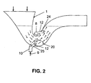
- the in the FIGS. 1 and 2 shown flushing device 1 has a toilet bowl 2, For example, ceramic, which has an inlet 3 and an outlet 18. Between the inlet 3 and the outlet 18 a siphon bend 4 is arranged, is stored in the water 13, which forms an odor trap.
- the outlet 18 is arranged at the end of a discharge pipe 5, which is connected in the usual way to a disposal line.
- water is supplied in the direction of the arrows 6, as in the case of the customary flushing channel (not shown here).
- the present in the Siphonbogen 4 water 13 is accelerated by means of a pulse nozzle device 8. With the impulse nozzle device 8, a plurality of flow cones 15 are generated in the water 13, which are directed against the outlet 18.
- the impulse nozzle device 8 has a distributor ring 11, which is in accordance with FIG. 1 extends around the siphon 4 around.
- This distributor ring 11 is connected via an inlet pipe 10 with a line not shown here.
- This line is, for example, a water pipe which is connected to a cistern, not shown here, for example, a pressure cistern or a conventional gravity based cistern.
- the inlet pipe 10 is arranged as shown in the lower region of the distributor ring 11. The water thus flows through the inlet tube 10 from below into the distributor ring 11 and is distributed in this to a plurality of nozzles 12.
- These nozzles 12 open at an inner side 21 of the siphon bend 4 in the interior 22 of the toilet bowl.
- An orifice 25 is located according to FIG.
- Another orifice 24 is located in an ascending region 4b of the siphon arc 4.
- the generated impulse, or flow cone is thus not only punctiform but is generated at several points, so that the water radiating from the nozzles 12 has a considerably higher impulse density and thus very high dynamic forces can be exerted on the water 13. At least a portion of these forces are exerted on the water 13 after the apex of the siphon bow 4, so that said suction effect is generated. The suction is applied until substantially all of the contents of the siphon sheet 4 are flushed out. Since a plurality of nozzles 12 are provided, the various flow parameters can be aligned with the siphon sheet 4.
- FIG. 3 shows a flushing device 1 ', which differs from the flushing device 1 by the formation of the pulse nozzle device 8'.
- This pulse nozzle device 8 ' also has several, that is, at least two nozzles 12', which are arranged here, however, only after the apex of the siphon sheet 4 and thus in the ascending region 4b.
- This arrangement produces a particularly high suction effect, in which the water 13 present in the rising region 4b moves upwards and thus towards the outlet 18, or is accelerated.
- the water 13 present in the lower region 4c and in the region 4a is also moved toward the outlet 18 due to the suction effect. Since the nozzles 12 'are arranged in front of the solid 20, the flow cone 15 generated by the nozzles 12' can not be deflected by this.
- FIG. 4 shows a siphon sheet 4, in which the water 13 is accelerated by means of only one nozzle 17 in a known manner.
- the water flowing into the siphon bend 4 forms a flow cone 14.
- the flow cone 14 Located in the flow direction after the nozzle 17, a solid 20, the flow cone 14 is deflected and may possibly even be directed against the flow direction.
- the inflowing water often forms air bubbles 16 'and corresponding turbulence. These turbulences are comparatively large and produce a comparatively high noise.
- a plurality of essentially concentric flow cones 15 are formed in the siphon bend 4. These also generate turbulence and air bubbles 16. It has been found that these turbulences produce a much lower noise and the air bubbles 16 are smaller than in the prior art according to FIG. 4 , It has also been shown that a buildup of the suction function takes place over a comparatively short distance 18. This route 18 is considerably shorter than the route 18 'according to FIG. 4 , With the multiple flow cones 15 a much more efficient transport away a solid 20 is possible. Accordingly, a certain self-cleaning of the siphon sheet 4 can be achieved. With the flow cones 15, adapted to the siphon bend 4, a flow pressure of, for example 0.04 bar and a higher flow pressure can be achieved. By appropriate arrangement of the nozzles 12 and 12 ', this flow pressure can be optimized.
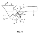
- FIG. 6 shows a flushing device 1 ", which differs from the flushing devices 1 and 1 'by the formation of the pulse nozzle device 8".
- the plurality of nozzles 12, or 12 ' instead of the plurality of nozzles 12, or 12 ', here at least one annular gap 19 is provided, which opens at the inner side 21 in the interior 22 of the siphon bend 4.
- an annular flow cone is produced here, which likewise has the effect of accelerating the water present in the rising region 4b towards the outlet 18.
- the effects are comparable to the flow cones 15 created with the impulse nozzle devices 8 and 8 '.
- the annular gap 19 is comparatively narrow, so that water flows into the interior 22 at a comparatively high speed and energy.
- the annular gap 19 may extend around the entire circumference of the siphon arc or around a part of the circumference. Also conceivable is a design with a plurality of annular gaps 19. It is conceivable, for example, a design with two approximately diametrically opposed annular gaps 19th
- the pulse generated by the pulse nozzle device 8, 8 'or 8 can be synchronous with the main rinse, however, it is also conceivable that the pulse and the main rinse be applied one after the other.
Landscapes
- Health & Medical Sciences (AREA)
- Life Sciences & Earth Sciences (AREA)
- Engineering & Computer Science (AREA)
- Hydrology & Water Resources (AREA)
- Public Health (AREA)
- Water Supply & Treatment (AREA)
- Sanitary Device For Flush Toilet (AREA)
- Bidet-Like Cleaning Device And Other Flush Toilet Accessories (AREA)
Abstract
Description
- Die Erfindung betrifft eine Spülvorrichtung für ein Wasserklosett, mit einer Klosettschüssel, die einen Einlass und einen Auslass und zwischen diesen in einem Siphonbogen Mittel zum Erzeugen eines Impulses aufweist, mit dem im Siphonbogen vorliegendes und einen Geruchsverschluss bildendes Wasser für einen Spülvorgang in Richtung des Auslasses beschleunigbar ist.
- Der Verbrauch von Spülwasser kann bei einem WC wesentlich gesenkt werden, wenn gemäss der
WO 95/04196 - Durch die
EP-A-1034338 ist ein Wasserklosett bekannt geworden, das eine sogenannte Jet-Düse aufweist. Durch die Düse wird ein Gemisch aus Wasser und Luft in den Boden der WC-Schlüssel eingespritzt. Am vorderen Ende der Düse ist eine Unterdruckkammer angeordnet, die gewährleisten soll, dass das Wasser-Luft-Gemisch in der Richtung der Achse des Eingangs des Siphons kanalisiert wird, wie es in Paragraph [0027] erwähnt ist. Durch das Einspritzen des genannten Gemisches dürfte ebenfalls zusätzliches Geräusch entstehen. - Untersuchungen haben gezeigt, dass beim Vorliegen von festen Bestandteilen im Siphon die beschleunigende Wirkung der Jet-Düse stark vermindert ist.
- Der Erfindung liegt die Aufgabe zugrunde, eine Spülvorrichtung der genannten Art zu schaffen, welche die genannten Nachteile vermeidet.
- Die Aufgabe ist gemäss Anspruch 1 dadurch gelöst, dass die Mittel zum Erzeugen eines Impulses mehrere Düsen oder wenigstens einen sich in Umfangsrichtung des Siphons erstreckenden Ringspalt aufweist, mit denen beziehungsweise mit dem jeweils im genannten Wasser eine im Wesentlich gegen den Auslass gerichtete Strömung erzeugbar ist.
- Bei der erfindungsgemässen Spülvorrichtung kann im Wasser des Siphonbogens eine Strömung mit einer wesentlich höheren Impulsdichte erzeugt werden. Die Impulsdichte ist wesentlich höher als diejenige, die mit lediglich einer Düse erzeugbar ist. Der bei der erfindungsgemässen Spülvorrichtung erzeugte Impuls ist zudem wesentlich stabiler und wird durch Hindernisse im Siphon wesentlich weniger abgelenkt. Der erzeugte Strömungskegel wird in die vorgesehene Wirkrichtung geleitet und konzentriert. Dies führt zu einem wirksameren Wegtransport von festen Gegenständen. Es hat sich zudem gezeigt, dass bei der erfindungsgemässen Spülvorrichtung beim Spülvorgang wesentlich kleinere Luftblasen im Siphon und entsprechend feineren Turbulenzen entstehen. Die Geräusche sind entsprechend tiefer und weniger störend als die hohen Geräusche, die bei der Verwendung von lediglich einer Jet-Düse erzeugt werden. Schliesslich hat sich gezeigt, dass die gewünschte Saugfunktion wesentlich schneller aufgebaut wird.
- Bei einer Weiterbildung der Erfindung ist vorgesehen, dass wenigstens eine der mehreren Düsen oder der Ringspalt unmittelbar vor oder in einem aufsteigenden Bereich des Siphonbogens angeordnet ist. Die Düse beziehungsweise der Ringspalt ist somit bei oder nach dem Scheitel des Siphonbogens angeordnet. Dadurch kann eine besonders wirksame Saugwirkung erzeugt werden. Der durch die Düsen beziehungsweise durch den Ringspalt erzeugte Impuls kann bewirken, dass im Siphon das Restwasser und die Festkörper in das Abgangsrohr hineingesaugt werden, um das ausgestossene Wasser zu ersetzen. Dieser Vorgang dauert an, bis der gesamte Inhalt der Klosettschlüssel ausgespült und die Wasserzufuhr zu den Düsen beziehungsweise zum Ringspalt ausgeschaltet wird.
- Vorzugsweise sind mehr als zwei Düsen über dem Umfang des Siphonbogens verteilt. Grundsätzlich ist aber auch eine Ausführung mit lediglich zwei Düsen denkbar. Hierbei sind die beiden Düsen vorzugsweise etwa diametral gegenüber angeordnet. Insbesondere sind hierbei eine Düse unten und eine Düse oben angeordnet. Der Ringspalt erstreckt sich vorzugsweise im Wesentlichen und im gesamten Umfang des Siphonbogens. Denkbar ist jedoch auch eine Ausführung, bei welcher sich der Ringspalt nur um einen Teil des Umfangs, beispielsweise um die Hälfte des Umfangs erstreckt. Denkbar ist auch eine Ausführung mit mehr als einem Ringspalt.
- Nach einer Weiterbildung der Erfindung ist vorgesehen, dass am Umfang des Siphonbogens eine Ringanschlussleitung angeordnet ist, mit der wenigstens zwei Düsen beziehungsweise der Ringspalt verbunden sind. Eine solche Ringanschlussleitung ermöglicht die Verteilung des Wassers oder eines anderen vorgesehenen Fluidums auf die mehreren Düsen beziehungsweise auf den Ringspalt zu verteilen. Eine solche Ringleitung könnte grundsätzlich in der Wandung des Siphonbogens oder im Abstand zur Aussenseite des Siphonbogens verlaufen. Die Zuführung erfolgt dann vorzugsweise über ein Einlassrohr, das mit der Anschlussdüse verbunden ist.
- Nach einer Weiterbildung der Erfindung ist vorgesehen, dass die Düsen beziehungsweise der Ringspalt für die Zufuhr von Wasser, Luft oder einem Gemisch von Wasser und Luft vorgesehen ist. Vorzugsweise sind die Düsen zum Einspritzen von Wasser mit einem vergleichsweise hohen Druck vorgesehen. Grundsätzlich könnte das im Siphon vorliegende Wasser jedoch auch mit Luft oder einem Gemisch aus Wasser und Luft beschleunigt werden.
- Nach dem Entleeren oder bereits während des Entleerens des Siphons wird vorzugsweise die Klosettschlüssel im Bereich des Einlasses mittels einer Hauptspülung gereinigt. Zudem ist vorgesehen, den Siphon nach dem Entleeren wieder mit Spülwasser zu füllen. Das Wasser zum Beschleunigen des Wassers im Siphon kann beispielsweise aus einem Spülkasten zugeführt werden. Der Spülkasten kann ebenfalls das Wasser für die Hauptspülung zur Verfügung stellen. Der Spülkasten kann hierbei ein üblicher Gravitationsspülkasten oder auch ein Druckspülkasten sein. Ein Teil des Wassers wird dann den genannten Düsen beziehungsweise dem wenigstens einen Ringspalt und ein anderer Teil dem Einlass der Klosettschüssel zugeführt.
- Die Erfindung betrifft auch ein Verfahren zum Betrieb einer Spülvorrichtung. Hierbei ist vorgesehen, dass mit den mehreren Düsen beziehungsweise mit dem Ringspalt das im Siphonbogen vorliegende Wasser zum Auslass hin beschleunigt wird. Die Beschleunigung des Wassers erfolgt somit nicht mit lediglich einer Düse, sondern mit mehreren Düsen beziehungsweise mit einem Ringspalt. Es sind mehrere Düsen vorgesehen, so werden im Siphonbogen entsprechend mehrere Strömungskegel gebildet, die jeweils im Wesentlichen gegen den Auslass gerichtet sind.
- Die Erzeugung des Impulses im Siphonbogen kann gleichzeitig mit der Hauptspülung erfolgen oder die Hauptspülung und die Impulserzeugung erfolgen nacheinander.
- Weitere vorteilhafte Merkmale ergeben sich aus den abhängigen Patentansprüchen, der nachfolgenden Beschreibung sowie der Zeichnung.
- Ausführungsbeispiele werden nachfolgend anhand der Zeichnung erläutert.
- Es zeigen:
- Fig. 1
- schematisch eine Ansicht einer erfindungsgemässen Spülvorrichtung;
- Fig. 2
- eine weitere schematische Ansicht de erfindungsgemässen Spülvorrichtung, wobei im Siphonbogen vorliegendes Wasser beschleunigt ist;
- Fig. 3
- eine schematische Ansicht einer Spülvorrichtung gemäss einer Variante;
- Fig. 4
- schematisch ein Teilschnitt durch einen Siphonbogen nach dem Stand der Technik;
- Fig. 5
- einen Teilschnitt durch einen Teil eines Siphonbogens gemäss der vorliegenden Erfindung; und
- Fig. 6
- schematisch eine Ansicht einer Spülvorrichtung nach einer weiteren Variante.
- Die in den
Figuren 1 und2 gezeigte Spülvorrichtung 1 weist eine WC-Schüssel 2 auf, beispielsweise aus Keramik, die einen Einlass 3 und einen Auslass 18 besitzt. Zwischen dem Einlass 3 und dem Auslass 18 ist ein Siphonbogen 4 angeordnet, in dem Wasser 13 gelagert ist, das einen Geruchsverschluss bildet. Der Auslass 18 ist am Ende eines Abgangsrohres 5 angeordnet, das in üblicher Weise an eine Entsorgungsleitung angeschlossen ist. Beim Spülvorgang wird, wie beim hier nicht gezeigten üblichen Spülkanal, in Richtung der Pfeile 6 Wasser zugeführt. Zusätzlich wird das im Siphonbogen 4 vorliegende Wasser 13 mittels einer Impulsdüsenvorrichtung 8 beschleunigt. Mit der Impulsdüsenvorrichtung 8 werden im Wasser 13 mehrere Strömungskegel 15 erzeugt, die gegen den Auslass 18 gerichtet sind. Diese Strömungskegel 15 stossen das nach der Impulsdüsenvorrichtung 8 vorliegende Wasser 13 gegen einen Innenraum 22 des Abgangsrohres 5 und somit nach oben und gegen den Auslass 18. Das restliche im Siphonbogen 4 vorliegende Wasser 13 wird dadurch angesaugt und ebenfalls gegen den Auslass 18 hin beschleunigt. Hierbei werden im Siphonbogen 4 vorliegende Festkörper 20 mitgerissen und ebenfalls zum Ausgang 18 hin befördert. Ist der Siphonbogen 4 im Wesentlichen leer, so wird dieser durch das über den genannten Spülkanal am Einlass 3 zugeführte Wasser wieder nachgefüllt. Dieses Wasser bildet die Hauptspülung und durch diese wird auch eine Innenseite 23 der WC-Schüssel 2 gereinigt. - Die Impulsdüsenvorrichtung 8 besitzt einen Verteilerring 11, der sich gemäss
Figur 1 um den Siphonbogen 4 herum erstreckt. Dieser Verteilerring 11 ist über ein Einlassrohr 10 mit einer hier nicht gezeigten Leitung verbunden. Diese Leitung ist beispielsweise eine Wasserleitung die mit einem hier nicht gezeigten Spülkasten, beispielsweise einem Druckspülkasten oder einem üblichen auf Gravitation beruhenden Spülkasten, verbunden ist. Das Einlassrohr 10 ist wie ersichtlich im unteren Bereich des Verteilerringes 11 angeordnet. Das Wasser strömt somit durch das Einlassrohr 10 von unten in den Verteilerring 11 und wird in diesem auf mehrere Düsen 12 verteilt. Diese Düsen 12 münden an einer Innenseite 21 des Siphonbogens 4 in den Innenraum 22 der WC-Schüssel. Eine Mündung 25 befindet sich gemässFigur 2 in einem unteren Bereich und im Wesentlichen im Scheitelpunkt eines Bereiches 4c des Siphonbogens 4. Eine andere Mündung 24 befindet sich in einem aufsteigenden Bereich 4b des Siphonbogens 4. Es sind wenigstens zwei Düsen 12 vorgesehen, die vorzugsweise wie gezeigt etwa diametral gegenüberliegen. Es können aber auch mehr als zwei Düsen 12, beispielsweise drei, vier oder auch mehr Düsen 12 vorgesehen sein. Diese sind am Umfang des Siphonbogens 4 verteilt. Die Verteilung kann gleichmässig oder ungleichmässig sein. Der erzeugte Impuls, beziehungsweise Strömungskegel, ist somit nicht nur punktuell, sondern wird an mehreren Stellen erzeugt, so dass das aus den Düsen 12 strahlende Wasser eine erheblich höhere Impulsdichte aufweist und dadurch können sehr hohe dynamische Kräfte auf das Wasser 13 ausgeübt werden. Wenigstens ein Teil dieser Kräfte wird nach dem Scheitelpunkt des Siphonbogens 4 auf das Wasser 13 ausgeübt, so dass die genannte Saugwirkung erzeugt wird. Die Saugwirkung wird ausgeübt, bis im Wesentlichen der gesamte Inhalt des Siphonbogens 4 ausgespült ist. Da mehrere Düsen 12 vorgesehen sind, können die verschiedenen Strömungsparameter auf den Siphonbogen 4 ausgerichtet werden. - Die
Figur 3 zeigt eine Spülvorrichtung 1', die sich von der Spülvorrichtung 1 durch die Ausbildung der Impulsdüsenvorrichtung 8' unterscheidet. Diese Impulsdüsenvorrichtung 8' besitzt ebenfalls mehrere, das heisst wenigstens zwei Düsen 12', die hier jedoch ausschliesslich nach dem Scheitelpunkt des Siphonbogens 4 und somit im aufsteigenden Bereich 4b angeordnet sind. Diese Anordnung erzeugt eine besonders hohe Saugwirkung, in dem das im aufsteigenden Bereich 4b vorliegende Wasser 13 nach oben und somit zum Auslass 18 hin bewegt, beziehungsweise beschleunigt wird. Das im unteren Bereich 4c und im Bereich 4a vorliegende Wasser 13 wird aufgrund der Sogwirkung ebenfalls zum Auslass 18 hin bewegt. Da die Düsen 12' vor dem Festkörper 20 angeordnet sind, können die durch die Düsen 12' erzeugten Strömungskegel 15 nicht durch diesen abgelenkt werden. - Anhand der
Figuren 4 und 5 wird nachfolgend der Unterschied zwischen einer Impulsdüsenvorrichtung mit lediglich einer Düse und einer erfindungsgemässen Impulsdüsenvorrichtung 8 erläutert. - Die
Figur 4 zeigt einen Siphonbogen 4, bei dem das Wasser 13 mittels lediglich einer Düse 17 in bekannter Weise beschleunigt wird. Durch das in den Siphonbogen 4 einströmende Wasser wird ein Strömungskegel 14 gebildet. Befindet sich in Strömungsrichtung gesehen nach der Düse 17 ein Festkörper 20, so wird der Strömungskegel 14 abgelenkt und kann eventuell sogar gegen die Strömungsrichtung gerichtet sein. Durch das einströmende Wasser bilden sich oft Luftblasen 16' und entsprechende Turbulenzen. Diese Turbulenzen sind vergleichsweise gross und erzeugen ein vergleichsweise hohes Geräusch. - Bei der erfindungsgemässen Spülvorrichtung werden wie oben erläutert im Siphonbogen 4 mehrere im Wesentlichen konzentrische Strömungskegel 15 gebildet. Diese erzeugen ebenfalls Turbulenzen und Luftblasen 16. Es hat sich gezeigt, dass diese Turbulenzen ein wesentlich tieferes Geräusch erzeugen und die Luftblasen 16 kleiner sind als beim Stand der Technik gemäss
Figur 4 . Es hat sich auch gezeigt, dass ein Aufbau der Saugfunktion über eine vergleichsweise kurze Strecke 18 erfolgt. Diese Strecke 18 ist wesentlich kürzer als die Strecke 18' gemässFigur 4 . Mit den mehreren Strömungskegeln 15 ist ein wesentlich effizienterer Wegtransport eines Festkörpers 20 möglich. Entsprechend kann eine gewisse Selbstreinigung des Siphonbogens 4 erreicht werden. Mit den Strömungskegeln 15 kann, angepasst an den Siphonbogen 4, ein Fliessdruck von beispielsweise 0.04 bar und auch ein höherer Fliessdruck erreicht werden. Durch entsprechende Anordnung der Düsen 12 beziehungsweise 12' kann dieser Fliessdruck optimiert werden. - Die
Figur 6 zeigt eine Spülvorrichtung 1", die sich von den Spülvorrichtungen 1 und 1' durch die Ausbildung der Impulsdüsenvorrichtung 8" unterscheidet. Anstelle der mehreren Düsen 12, beziehungsweise 12', ist hier wenigstens ein Ringspalt 19 vorgesehen, der an der Innenseite 21 in den Innenraum 22 des Siphonbogens 4 mündet. Anstelle von mehreren Strömungskegeln 15 wird hier ein ringförmiger Strömungskegel erzeugt, der ebenfalls die Wirkung hat, dass das im aufsteigenden Bereich 4b vorliegende Wasser gegen den Auslass 18 hin beschleunigt wird. Die Wirkungen sind vergleichbar mit den Strömungskegeln 15, die mit den Impulsdüsenvorrichtungen 8 und 8' erzeugt werden. Der Ringspalt 19 ist vergleichsweise schmal, so dass Wasser mit einer vergleichsweise hohen Geschwindigkeit und Energie in den Innenraum 22 strömt. Der Ringspalt 19 kann sich um den gesamten Umfang des Siphonbogens oder auch um einen Teil des Umfangs erstrecken. Denkbar ist auch eine Ausführung mit mehreren Ringspalten 19. Denkbar ist beispielsweise eine Ausführung mit zwei etwa diametral gegenüberliegenden Ringspalten 19. - Der durch die Impulsdüsenvorrichtung 8, 8' beziehungsweise 8" erzeugte Impuls kann synchron zur Hauptspülung erfolgen. Denkbar ist jedoch auch eine Ausführung, bei welcher der Impuls und die Hauptspülung nacheinander ausgeübt werden. Insbesondere kann der Impuls im Siphonbogen 4 vor Auslösen der Hauptspülung erfolgen.
-
- 1
- Spülvorrichtung
- 2
- WC-Schüssel
- 3
- Einlass
- 4
- Siphonbogen
- 5
- Abgangsrohr
- 6
- Pfeil
- 7
- Pfeil
- 8
- Impulsdüsen
- 9
- Pfeil
- 10
- Einlassrohr
- 11
- Verteilerring
- 12
- Düse
- 13
- Wasser
- 14
- Strömungskegel
- 15
- Strömungskegel
- 16
- Luftblasen
- 17
- Düse
- 18
- Auslass
- 19
- Ringspalt
- 20
- Festkörper
- 21
- Innenseite
- 22
- Innenraum
- 23
- Innenseite
- 24
- Mündung
- 25
- Mündung
Claims (13)
- Spülvorrichtung für ein Wasserklosett, mit einer Klosettschüssel (2), die einen Einlass (3) und einen Auslass (18) und zwischen diesen in einem Siphonbogen (4) Mittel (12) zum Erzeugen eines Impulses aufweist, mit dem im Siphonbogen (4) vorliegendes und einen Geruchsverschluss bildendes Wasser für einen Spülvorgang in Richtung des Auslasses (18) beschleunigbar ist, dadurch gekennzeichnet, dass die Mittel (12) zum Erzeugen eines Impulses mehrere Düsen (12, 12') oder wenigstens einen sich in Umfangsrichtung des Siphonbogens (4) erstreckenden Ringspalt (19) aufweisen, mit denen beziehungsweise mit dem jeweils im genannten Wasser (13) eine im Wesentlichen gegen den Auslass (18) gerichtete Strömung erzeugbar ist.
- Spülvorrichtung nach Anspruch 1, dadurch gekennzeichnet, dass wenigstens eine Düse (12, 12') oder der wenigstens eine Ringspalt (19) unmittelbar vor oder in einem aufsteigenden Bereich (4b) des Siphonbogens (4) angeordnet ist.
- Spülvorrichtung nach Anspruch 1, dadurch gekennzeichnet, dass sämtliche Düsen (12, 12') beziehungsweise der wenigstens eine Ringspalt (19) im aufsteigenden Bereich (4b) des Siphonbogens (4) angeordnet sind beziehungsweise ist.
- Spülvorrichtung nach einem der Ansprüche 1 bis 3, dadurch gekennzeichnet, dass sich der Ringspalt (19) um den gesamten Umfang oder um einen Teil des Umfangs des Siphonbogens (4) erstreckt.
- Spülvorrichtung nach einem der Ansprüche 1 bis 4, dadurch gekennzeichnet, dass am Umfang des Siphonbogens (4) ein Verteilerring (11) angeordnet ist, welcher mit wenigstens zwei Düsen (12, 12') beziehungsweise mit dem Ringspalt (19) verbunden ist.
- Spülvorrichtung nach einem der Ansprüche 1 bis 5, dadurch gekennzeichnet, dass die Düsenkammer (12, 12') beziehungsweise der Ringspalt für die Zuführung von Wasser, Luft oder einem Gemisch von Wasser und Luft vorgesehen ist.
- Spülvorrichtung nach einem der Ansprüche 1 bis 6, dadurch gekennzeichnet, dass die Klosettschüssel (2) im Bereich des Einlasses (3) Mittel für eine Hauptspülung aufweist.
- Spülvorrichtung nach einem der Ansprüche 1 bis 7, dadurch gekennzeichnet, dass sie einen Spülkasten aufweist, der an die Klosettschüssel (2) angeschlossen ist und mit den wenigstens zwei Düsen (12, 12') beziehungsweise dem Ringspalt (19) Wasser zuführbar ist.
- Spülvorrichtung nach Anspruch 7, dadurch gekennzeichnet, dass der Spülkasten ein Druckspülkasten ist und dass dieser eine Leitung zu den wenigstens zwei Düsen (12, 12') beziehungsweise zum Ringspalt (199 aufweist.
- Verfahren zum Betrieb einer Spülvorrichtung nach einem der Ansprüche 1 bis 9, dadurch gekennzeichnet, dass bei einer Spülung mit den wenigstens zwei Düsen (12, 12') beziehungsweise dem Ringspalt (19) das im Siphon vorliegende Wasser zum Auslass hin beschleunigt wird.
- Verfahren nach Anspruch 10, dadurch gekennzeichnet, dass bei einer Spülung im Siphonbogen (4) mehrere Strömungskegel (15) gebildet werden, die im Wesentlichen gegen den Auslass (18) hin gerichtet sind.
- Verfahren nach Anspruch 10 oder 11, dadurch gekennzeichnet, dass bei einer Spülung die Klosettschlüssel (2) mit einer Hauptspülung gespült wird und dass diese auf dem im Siphonbogen (4) erzeugten Impuls abgestimmt ist.
- Verfahren nach Anspruch 12, dadurch gekennzeichnet, dass die Hauptspülung und der genannte Impuls nacheinander und im Wesentlichen gleichzeitig erzeugt werden.
Priority Applications (7)
| Application Number | Priority Date | Filing Date | Title |
|---|---|---|---|
| EP09405057.2A EP2233651B1 (de) | 2009-03-27 | 2009-03-27 | Spülvorrichtung für ein Wasserklosett sowie Verfahren zum Betrieb einer solchen Spülvorrichtung |
| EP09405125.7A EP2233652B1 (de) | 2009-03-27 | 2009-07-24 | Spülvorrichtung für ein Wasserklosett sowie Verfahren zum Betrieb einer solchen Spülvorrichtung |
| AU2010200694A AU2010200694B2 (en) | 2009-03-27 | 2010-02-25 | Flushing arrangement for a WC, and method of operating such a flushing arrangement |
| US12/714,067 US8713722B2 (en) | 2009-03-27 | 2010-02-26 | Flushing arrangement for a WC, and method of operating such a flushing arrangement |
| CN201010149047.6A CN101845846B (zh) | 2009-03-27 | 2010-03-25 | 用于wc的冲洗装置以及操作该冲洗装置的方法 |
| AU2010202596A AU2010202596B2 (en) | 2009-03-27 | 2010-06-22 | Flushing arrangement for a WC and method of operating such a flushing arrangement |
| US12/836,354 US8327472B2 (en) | 2009-03-27 | 2010-07-14 | Flushing arrangement for a WC and method of operating such a flushing arrangement |
Applications Claiming Priority (1)
| Application Number | Priority Date | Filing Date | Title |
|---|---|---|---|
| EP09405057.2A EP2233651B1 (de) | 2009-03-27 | 2009-03-27 | Spülvorrichtung für ein Wasserklosett sowie Verfahren zum Betrieb einer solchen Spülvorrichtung |
Publications (2)
| Publication Number | Publication Date |
|---|---|
| EP2233651A1 true EP2233651A1 (de) | 2010-09-29 |
| EP2233651B1 EP2233651B1 (de) | 2016-12-14 |
Family
ID=40983614
Family Applications (2)
| Application Number | Title | Priority Date | Filing Date |
|---|---|---|---|
| EP09405057.2A Active EP2233651B1 (de) | 2009-03-27 | 2009-03-27 | Spülvorrichtung für ein Wasserklosett sowie Verfahren zum Betrieb einer solchen Spülvorrichtung |
| EP09405125.7A Active EP2233652B1 (de) | 2009-03-27 | 2009-07-24 | Spülvorrichtung für ein Wasserklosett sowie Verfahren zum Betrieb einer solchen Spülvorrichtung |
Family Applications After (1)
| Application Number | Title | Priority Date | Filing Date |
|---|---|---|---|
| EP09405125.7A Active EP2233652B1 (de) | 2009-03-27 | 2009-07-24 | Spülvorrichtung für ein Wasserklosett sowie Verfahren zum Betrieb einer solchen Spülvorrichtung |
Country Status (4)
| Country | Link |
|---|---|
| US (2) | US8713722B2 (de) |
| EP (2) | EP2233651B1 (de) |
| CN (1) | CN101845846B (de) |
| AU (2) | AU2010200694B2 (de) |
Cited By (1)
| Publication number | Priority date | Publication date | Assignee | Title |
|---|---|---|---|---|
| DE102018121465A1 (de) | 2017-11-17 | 2019-05-23 | Villeroy & Boch Ag | Spültoilette |
Families Citing this family (9)
| Publication number | Priority date | Publication date | Assignee | Title |
|---|---|---|---|---|
| CA2858711C (en) * | 2010-11-16 | 2016-05-17 | Sdb Ip Holdings, Llc | Toilet fixture with directional jet flow |
| CN102267468B (zh) * | 2011-06-17 | 2013-06-12 | 西南交通大学 | 一种客车气冲节水坐便器 |
| SE1351084A1 (sv) * | 2013-09-19 | 2014-09-30 | Cdup Ab | En snålspolande toalett |
| CN105239653B (zh) * | 2014-07-08 | 2017-11-24 | 北京康之维科技有限公司 | 便器射流底冲方法及节水型存水湾便器 |
| RU2620302C2 (ru) * | 2015-06-08 | 2017-05-24 | Общество С Ограниченной Ответственностью Научно-Производственный Центр "Экспресс" (Ооо Нпц "Экспресс") | Способ очистки природоподобного туалета |
| CN108474201B (zh) * | 2016-01-25 | 2021-03-02 | 科勒公司 | 管线压力驱动的无箱式虹吸马桶 |
| GB201815488D0 (en) * | 2018-09-24 | 2018-11-07 | Bubblebog Ltd | Improvements in or relating to lavatories |
| CN110835945B (zh) * | 2019-11-15 | 2021-04-23 | 沧州佳宜洁环保科技有限公司 | 一种防臭型蹲便器 |
| IL300232B2 (en) * | 2023-01-26 | 2025-10-01 | Loocid Air Ltd | System and method for controlling and transferring gas on deck |
Citations (5)
| Publication number | Priority date | Publication date | Assignee | Title |
|---|---|---|---|---|
| US1785198A (en) * | 1929-11-25 | 1930-12-16 | Howard F Kelso | Water-closet bowl |
| US4967425A (en) * | 1984-10-12 | 1990-11-06 | Toto, Ltd. | Sanitary equipment for clean room |
| WO1995004196A1 (de) | 1993-08-02 | 1995-02-09 | Geberit Technik Ag | Spülvorrichtung für ein wasserklosett |
| EP1034338A1 (de) | 1997-11-26 | 2000-09-13 | Clara S.A. | Sanitäre einrichtung versehen mit einem siphon |
| WO2008024005A2 (en) * | 2006-08-23 | 2008-02-28 | Bernstein Research Limited | A toilet and associated apparatuses |
Family Cites Families (9)
| Publication number | Priority date | Publication date | Assignee | Title |
|---|---|---|---|---|
| US287225A (en) * | 1883-10-23 | William p | ||
| US3984878A (en) * | 1975-09-25 | 1976-10-12 | Grasseschi John J | Water closet |
| US4987616A (en) * | 1988-10-13 | 1991-01-29 | Eljer Manufacturing, Inc. | Water saver water closet |
| ATE162871T1 (de) * | 1990-11-16 | 1998-02-15 | Colivier Pty Ltd | Sprühvorrichtung für ein wc-untergestell |
| DE4201986C1 (de) * | 1992-01-25 | 1993-04-15 | Deutsche Airbus Gmbh, 2000 Hamburg, De | |
| JP2002088883A (ja) * | 2000-09-21 | 2002-03-27 | Toto Ltd | サイホンジェット式水洗便器 |
| CN2493670Y (zh) * | 2001-04-13 | 2002-05-29 | 刘增录 | 程控引射式坐便器 |
| US8082605B2 (en) * | 2006-09-08 | 2011-12-27 | Dan Marius Andreiu | Low flow hygienic apparatus and methods |
| CN201027343Y (zh) * | 2007-04-25 | 2008-02-27 | 虞吉伟 | 斜冲虹吸式座便器 |
-
2009
- 2009-03-27 EP EP09405057.2A patent/EP2233651B1/de active Active
- 2009-07-24 EP EP09405125.7A patent/EP2233652B1/de active Active
-
2010
- 2010-02-25 AU AU2010200694A patent/AU2010200694B2/en not_active Ceased
- 2010-02-26 US US12/714,067 patent/US8713722B2/en not_active Expired - Fee Related
- 2010-03-25 CN CN201010149047.6A patent/CN101845846B/zh not_active Expired - Fee Related
- 2010-06-22 AU AU2010202596A patent/AU2010202596B2/en not_active Ceased
- 2010-07-14 US US12/836,354 patent/US8327472B2/en not_active Expired - Fee Related
Patent Citations (5)
| Publication number | Priority date | Publication date | Assignee | Title |
|---|---|---|---|---|
| US1785198A (en) * | 1929-11-25 | 1930-12-16 | Howard F Kelso | Water-closet bowl |
| US4967425A (en) * | 1984-10-12 | 1990-11-06 | Toto, Ltd. | Sanitary equipment for clean room |
| WO1995004196A1 (de) | 1993-08-02 | 1995-02-09 | Geberit Technik Ag | Spülvorrichtung für ein wasserklosett |
| EP1034338A1 (de) | 1997-11-26 | 2000-09-13 | Clara S.A. | Sanitäre einrichtung versehen mit einem siphon |
| WO2008024005A2 (en) * | 2006-08-23 | 2008-02-28 | Bernstein Research Limited | A toilet and associated apparatuses |
Cited By (1)
| Publication number | Priority date | Publication date | Assignee | Title |
|---|---|---|---|---|
| DE102018121465A1 (de) | 2017-11-17 | 2019-05-23 | Villeroy & Boch Ag | Spültoilette |
Also Published As
| Publication number | Publication date |
|---|---|
| AU2010200694B2 (en) | 2016-03-10 |
| US20110016623A1 (en) | 2011-01-27 |
| AU2010200694A1 (en) | 2010-10-14 |
| US8713722B2 (en) | 2014-05-06 |
| CN101845846A (zh) | 2010-09-29 |
| CN101845846B (zh) | 2015-01-21 |
| EP2233652B1 (de) | 2015-10-07 |
| EP2233651B1 (de) | 2016-12-14 |
| US8327472B2 (en) | 2012-12-11 |
| AU2010202596A1 (en) | 2011-02-10 |
| EP2233652A1 (de) | 2010-09-29 |
| US20100242163A1 (en) | 2010-09-30 |
| AU2010202596B2 (en) | 2016-01-21 |
Similar Documents
| Publication | Publication Date | Title |
|---|---|---|
| EP2233651B1 (de) | Spülvorrichtung für ein Wasserklosett sowie Verfahren zum Betrieb einer solchen Spülvorrichtung | |
| EP3047077B1 (de) | Vakuumtoilette mit wechselseitiger quetschventilschliessung | |
| DE60113770T2 (de) | Reinigungsdüse und Reinigungsgerät | |
| DE102007013949A1 (de) | Spülanordnung und -verfahren für Vakuumtoiletten | |
| EP1566352B1 (de) | Pulverförderpumpe und zugehöriges Betriebsverfahren | |
| DE69424025T2 (de) | Druckluftgetriebene Vakkum-Abwasservorrichtung | |
| EP2309065B1 (de) | Verfahren zum Spülen einer einen Siphon aufweisenden Klosettschüssel und Wasserklosett | |
| EP2402519A1 (de) | Spülvorrichtung zum Spülen einer Klosettschüssel, Wasserklosett mit einer solchen Spülvorrichtung und Klosettschüssel | |
| EP2578319B1 (de) | Brausekopf | |
| DE102007031903A1 (de) | Spülvorrichtung für eine Vakuumtoilette mit einer Düsenanordnung | |
| EP1854926B1 (de) | Ablaufgarnitur für einen Spülkasten | |
| EP2843142B1 (de) | Verfahren zur Spülung einer Toilette, Toilettensystem und Freizeitmobil mit einem Toilettensystem | |
| DE102009013763B4 (de) | Sandfang für Kläranlagen, Wasserreinigungsanlagen und dergleichen | |
| EP0257298B1 (de) | Verfahren und Vorrichtung zur Reinigung von Flüssigkeitsbehältern | |
| EP1526222B1 (de) | Spülkasten mit Spülstromverteiler | |
| DE102014015991B4 (de) | Entsorgungsvorrichtung für ein Flugzeug sowie Flugzeug mit der Entsorgungsvorrichtung | |
| EP1832689B1 (de) | Unterdruckabwassereinrichtung | |
| EP2765249A1 (de) | Ablaufgarnitur für einen Spülkasten | |
| DE4207836C2 (de) | Vorrichtung zum Reinigen von Klar- oder Abwasserkanälen oder verlegten Rohrleitungen | |
| DE102008008701A1 (de) | Verfahren und Vorrichtung zur Erzeugung eines Wasser-Abrasivstrahls | |
| DE102013008435A1 (de) | Verfahren und Vorrichtung zum direkten Aufheizen von Flüssigkeiten zur Nassbehandlung von insbesondere Wäschestücken mit Dampf | |
| EP4127339B1 (de) | Reinigungsdüse zum reinigen einer bidet-duscheinrichtug | |
| DE4436765C2 (de) | Verfahren und Vorrichtung zur Reinigung von Flüssigkeitsbehältern | |
| EP4283057A1 (de) | Spülwasserverteiler | |
| DE102008063413A1 (de) | Längssandfang in Kläranlagen, Wasserreinigungsanlagen und dergleichen |
Legal Events
| Date | Code | Title | Description |
|---|---|---|---|
| PUAI | Public reference made under article 153(3) epc to a published international application that has entered the european phase |
Free format text: ORIGINAL CODE: 0009012 |
|
| AK | Designated contracting states |
Kind code of ref document: A1 Designated state(s): AT BE BG CH CY CZ DE DK EE ES FI FR GB GR HR HU IE IS IT LI LT LU LV MC MK MT NL NO PL PT RO SE SI SK TR |
|
| AX | Request for extension of the european patent |
Extension state: AL BA RS |
|
| 17P | Request for examination filed |
Effective date: 20101027 |
|
| 17Q | First examination report despatched |
Effective date: 20101203 |
|
| AKX | Designation fees paid |
Designated state(s): AT BE BG CH CY CZ DE DK EE ES FI FR GB GR HR HU IE IS IT LI LT LU LV MC MK MT NL NO PL PT RO SE SI SK TR |
|
| GRAP | Despatch of communication of intention to grant a patent |
Free format text: ORIGINAL CODE: EPIDOSNIGR1 |
|
| INTG | Intention to grant announced |
Effective date: 20151105 |
|
| GRAP | Despatch of communication of intention to grant a patent |
Free format text: ORIGINAL CODE: EPIDOSNIGR1 |
|
| INTG | Intention to grant announced |
Effective date: 20160420 |
|
| GRAS | Grant fee paid |
Free format text: ORIGINAL CODE: EPIDOSNIGR3 |
|
| GRAA | (expected) grant |
Free format text: ORIGINAL CODE: 0009210 |
|
| AK | Designated contracting states |
Kind code of ref document: B1 Designated state(s): AT BE BG CH CY CZ DE DK EE ES FI FR GB GR HR HU IE IS IT LI LT LU LV MC MK MT NL NO PL PT RO SE SI SK TR |
|
| REG | Reference to a national code |
Ref country code: GB Ref legal event code: FG4D Free format text: NOT ENGLISH |
|
| REG | Reference to a national code |
Ref country code: CH Ref legal event code: EP |
|
| REG | Reference to a national code |
Ref country code: IE Ref legal event code: FG4D Free format text: LANGUAGE OF EP DOCUMENT: GERMAN |
|
| REG | Reference to a national code |
Ref country code: CH Ref legal event code: NV Representative=s name: ISLER AND PEDRAZZINI AG, CH |
|
| REG | Reference to a national code |
Ref country code: AT Ref legal event code: REF Ref document number: 853722 Country of ref document: AT Kind code of ref document: T Effective date: 20170115 |
|
| REG | Reference to a national code |
Ref country code: FR Ref legal event code: PLFP Year of fee payment: 9 |
|
| REG | Reference to a national code |
Ref country code: DE Ref legal event code: R096 Ref document number: 502009013470 Country of ref document: DE |
|
| PG25 | Lapsed in a contracting state [announced via postgrant information from national office to epo] |
Ref country code: LV Free format text: LAPSE BECAUSE OF FAILURE TO SUBMIT A TRANSLATION OF THE DESCRIPTION OR TO PAY THE FEE WITHIN THE PRESCRIBED TIME-LIMIT Effective date: 20161214 |
|
| REG | Reference to a national code |
Ref country code: NL Ref legal event code: FP |
|
| REG | Reference to a national code |
Ref country code: LT Ref legal event code: MG4D |
|
| PG25 | Lapsed in a contracting state [announced via postgrant information from national office to epo] |
Ref country code: GR Free format text: LAPSE BECAUSE OF FAILURE TO SUBMIT A TRANSLATION OF THE DESCRIPTION OR TO PAY THE FEE WITHIN THE PRESCRIBED TIME-LIMIT Effective date: 20170315 Ref country code: LT Free format text: LAPSE BECAUSE OF FAILURE TO SUBMIT A TRANSLATION OF THE DESCRIPTION OR TO PAY THE FEE WITHIN THE PRESCRIBED TIME-LIMIT Effective date: 20161214 Ref country code: NO Free format text: LAPSE BECAUSE OF FAILURE TO SUBMIT A TRANSLATION OF THE DESCRIPTION OR TO PAY THE FEE WITHIN THE PRESCRIBED TIME-LIMIT Effective date: 20170314 Ref country code: SE Free format text: LAPSE BECAUSE OF FAILURE TO SUBMIT A TRANSLATION OF THE DESCRIPTION OR TO PAY THE FEE WITHIN THE PRESCRIBED TIME-LIMIT Effective date: 20161214 |
|
| PG25 | Lapsed in a contracting state [announced via postgrant information from national office to epo] |
Ref country code: FI Free format text: LAPSE BECAUSE OF FAILURE TO SUBMIT A TRANSLATION OF THE DESCRIPTION OR TO PAY THE FEE WITHIN THE PRESCRIBED TIME-LIMIT Effective date: 20161214 Ref country code: HR Free format text: LAPSE BECAUSE OF FAILURE TO SUBMIT A TRANSLATION OF THE DESCRIPTION OR TO PAY THE FEE WITHIN THE PRESCRIBED TIME-LIMIT Effective date: 20161214 |
|
| PG25 | Lapsed in a contracting state [announced via postgrant information from national office to epo] |
Ref country code: RO Free format text: LAPSE BECAUSE OF FAILURE TO SUBMIT A TRANSLATION OF THE DESCRIPTION OR TO PAY THE FEE WITHIN THE PRESCRIBED TIME-LIMIT Effective date: 20161214 Ref country code: IS Free format text: LAPSE BECAUSE OF FAILURE TO SUBMIT A TRANSLATION OF THE DESCRIPTION OR TO PAY THE FEE WITHIN THE PRESCRIBED TIME-LIMIT Effective date: 20170414 Ref country code: EE Free format text: LAPSE BECAUSE OF FAILURE TO SUBMIT A TRANSLATION OF THE DESCRIPTION OR TO PAY THE FEE WITHIN THE PRESCRIBED TIME-LIMIT Effective date: 20161214 Ref country code: CZ Free format text: LAPSE BECAUSE OF FAILURE TO SUBMIT A TRANSLATION OF THE DESCRIPTION OR TO PAY THE FEE WITHIN THE PRESCRIBED TIME-LIMIT Effective date: 20161214 Ref country code: SK Free format text: LAPSE BECAUSE OF FAILURE TO SUBMIT A TRANSLATION OF THE DESCRIPTION OR TO PAY THE FEE WITHIN THE PRESCRIBED TIME-LIMIT Effective date: 20161214 |
|
| PG25 | Lapsed in a contracting state [announced via postgrant information from national office to epo] |
Ref country code: PT Free format text: LAPSE BECAUSE OF FAILURE TO SUBMIT A TRANSLATION OF THE DESCRIPTION OR TO PAY THE FEE WITHIN THE PRESCRIBED TIME-LIMIT Effective date: 20170414 Ref country code: ES Free format text: LAPSE BECAUSE OF FAILURE TO SUBMIT A TRANSLATION OF THE DESCRIPTION OR TO PAY THE FEE WITHIN THE PRESCRIBED TIME-LIMIT Effective date: 20161214 Ref country code: PL Free format text: LAPSE BECAUSE OF FAILURE TO SUBMIT A TRANSLATION OF THE DESCRIPTION OR TO PAY THE FEE WITHIN THE PRESCRIBED TIME-LIMIT Effective date: 20161214 Ref country code: BG Free format text: LAPSE BECAUSE OF FAILURE TO SUBMIT A TRANSLATION OF THE DESCRIPTION OR TO PAY THE FEE WITHIN THE PRESCRIBED TIME-LIMIT Effective date: 20170314 |
|
| REG | Reference to a national code |
Ref country code: DE Ref legal event code: R097 Ref document number: 502009013470 Country of ref document: DE |
|
| PLBE | No opposition filed within time limit |
Free format text: ORIGINAL CODE: 0009261 |
|
| STAA | Information on the status of an ep patent application or granted ep patent |
Free format text: STATUS: NO OPPOSITION FILED WITHIN TIME LIMIT |
|
| 26N | No opposition filed |
Effective date: 20170915 |
|
| PG25 | Lapsed in a contracting state [announced via postgrant information from national office to epo] |
Ref country code: DK Free format text: LAPSE BECAUSE OF FAILURE TO SUBMIT A TRANSLATION OF THE DESCRIPTION OR TO PAY THE FEE WITHIN THE PRESCRIBED TIME-LIMIT Effective date: 20161214 Ref country code: MC Free format text: LAPSE BECAUSE OF FAILURE TO SUBMIT A TRANSLATION OF THE DESCRIPTION OR TO PAY THE FEE WITHIN THE PRESCRIBED TIME-LIMIT Effective date: 20161214 |
|
| REG | Reference to a national code |
Ref country code: IE Ref legal event code: MM4A |
|
| PG25 | Lapsed in a contracting state [announced via postgrant information from national office to epo] |
Ref country code: LU Free format text: LAPSE BECAUSE OF NON-PAYMENT OF DUE FEES Effective date: 20170327 |
|
| PG25 | Lapsed in a contracting state [announced via postgrant information from national office to epo] |
Ref country code: SI Free format text: LAPSE BECAUSE OF FAILURE TO SUBMIT A TRANSLATION OF THE DESCRIPTION OR TO PAY THE FEE WITHIN THE PRESCRIBED TIME-LIMIT Effective date: 20161214 Ref country code: IE Free format text: LAPSE BECAUSE OF NON-PAYMENT OF DUE FEES Effective date: 20170327 |
|
| REG | Reference to a national code |
Ref country code: FR Ref legal event code: PLFP Year of fee payment: 10 |
|
| PG25 | Lapsed in a contracting state [announced via postgrant information from national office to epo] |
Ref country code: MT Free format text: LAPSE BECAUSE OF FAILURE TO SUBMIT A TRANSLATION OF THE DESCRIPTION OR TO PAY THE FEE WITHIN THE PRESCRIBED TIME-LIMIT Effective date: 20161214 |
|
| PG25 | Lapsed in a contracting state [announced via postgrant information from national office to epo] |
Ref country code: HU Free format text: LAPSE BECAUSE OF FAILURE TO SUBMIT A TRANSLATION OF THE DESCRIPTION OR TO PAY THE FEE WITHIN THE PRESCRIBED TIME-LIMIT; INVALID AB INITIO Effective date: 20090327 |
|
| PG25 | Lapsed in a contracting state [announced via postgrant information from national office to epo] |
Ref country code: CY Free format text: LAPSE BECAUSE OF NON-PAYMENT OF DUE FEES Effective date: 20161214 |
|
| PG25 | Lapsed in a contracting state [announced via postgrant information from national office to epo] |
Ref country code: MK Free format text: LAPSE BECAUSE OF FAILURE TO SUBMIT A TRANSLATION OF THE DESCRIPTION OR TO PAY THE FEE WITHIN THE PRESCRIBED TIME-LIMIT Effective date: 20161214 |
|
| PG25 | Lapsed in a contracting state [announced via postgrant information from national office to epo] |
Ref country code: TR Free format text: LAPSE BECAUSE OF FAILURE TO SUBMIT A TRANSLATION OF THE DESCRIPTION OR TO PAY THE FEE WITHIN THE PRESCRIBED TIME-LIMIT Effective date: 20161214 |
|
| PGFP | Annual fee paid to national office [announced via postgrant information from national office to epo] |
Ref country code: NL Payment date: 20200319 Year of fee payment: 12 Ref country code: IT Payment date: 20200323 Year of fee payment: 12 Ref country code: GB Payment date: 20200323 Year of fee payment: 12 |
|
| PGFP | Annual fee paid to national office [announced via postgrant information from national office to epo] |
Ref country code: BE Payment date: 20200319 Year of fee payment: 12 |
|
| PGFP | Annual fee paid to national office [announced via postgrant information from national office to epo] |
Ref country code: FR Payment date: 20200320 Year of fee payment: 12 |
|
| PGFP | Annual fee paid to national office [announced via postgrant information from national office to epo] |
Ref country code: AT Payment date: 20210322 Year of fee payment: 13 |
|
| REG | Reference to a national code |
Ref country code: NL Ref legal event code: MM Effective date: 20210401 |
|
| GBPC | Gb: european patent ceased through non-payment of renewal fee |
Effective date: 20210327 |
|
| REG | Reference to a national code |
Ref country code: BE Ref legal event code: MM Effective date: 20210331 |
|
| PG25 | Lapsed in a contracting state [announced via postgrant information from national office to epo] |
Ref country code: FR Free format text: LAPSE BECAUSE OF NON-PAYMENT OF DUE FEES Effective date: 20210331 Ref country code: GB Free format text: LAPSE BECAUSE OF NON-PAYMENT OF DUE FEES Effective date: 20210327 Ref country code: NL Free format text: LAPSE BECAUSE OF NON-PAYMENT OF DUE FEES Effective date: 20210401 |
|
| PG25 | Lapsed in a contracting state [announced via postgrant information from national office to epo] |
Ref country code: IT Free format text: LAPSE BECAUSE OF NON-PAYMENT OF DUE FEES Effective date: 20210327 |
|
| PG25 | Lapsed in a contracting state [announced via postgrant information from national office to epo] |
Ref country code: BE Free format text: LAPSE BECAUSE OF NON-PAYMENT OF DUE FEES Effective date: 20210331 |
|
| REG | Reference to a national code |
Ref country code: AT Ref legal event code: MM01 Ref document number: 853722 Country of ref document: AT Kind code of ref document: T Effective date: 20220327 |
|
| PG25 | Lapsed in a contracting state [announced via postgrant information from national office to epo] |
Ref country code: AT Free format text: LAPSE BECAUSE OF NON-PAYMENT OF DUE FEES Effective date: 20220327 |
|
| PGFP | Annual fee paid to national office [announced via postgrant information from national office to epo] |
Ref country code: CH Payment date: 20250401 Year of fee payment: 17 |
|
| REG | Reference to a national code |
Ref country code: CH Ref legal event code: U11 Free format text: ST27 STATUS EVENT CODE: U-0-0-U10-U11 (AS PROVIDED BY THE NATIONAL OFFICE) Effective date: 20260401 |
|
| PGFP | Annual fee paid to national office [announced via postgrant information from national office to epo] |
Ref country code: DE Payment date: 20260319 Year of fee payment: 18 |