EP2231300B1 - Filter device - Google Patents
Filter device Download PDFInfo
- Publication number
- EP2231300B1 EP2231300B1 EP08867451.0A EP08867451A EP2231300B1 EP 2231300 B1 EP2231300 B1 EP 2231300B1 EP 08867451 A EP08867451 A EP 08867451A EP 2231300 B1 EP2231300 B1 EP 2231300B1
- Authority
- EP
- European Patent Office
- Prior art keywords
- filter
- filter device
- substrate
- filter media
- attached
- Prior art date
- Legal status (The legal status is an assumption and is not a legal conclusion. Google has not performed a legal analysis and makes no representation as to the accuracy of the status listed.)
- Not-in-force
Links
Images


Classifications
-
- B—PERFORMING OPERATIONS; TRANSPORTING
- B01—PHYSICAL OR CHEMICAL PROCESSES OR APPARATUS IN GENERAL
- B01D—SEPARATION
- B01D29/00—Filters with filtering elements stationary during filtration, e.g. pressure or suction filters, not covered by groups B01D24/00 - B01D27/00; Filtering elements therefor
- B01D29/01—Filters with filtering elements stationary during filtration, e.g. pressure or suction filters, not covered by groups B01D24/00 - B01D27/00; Filtering elements therefor with flat filtering elements
- B01D29/05—Filters with filtering elements stationary during filtration, e.g. pressure or suction filters, not covered by groups B01D24/00 - B01D27/00; Filtering elements therefor with flat filtering elements supported
-
- B—PERFORMING OPERATIONS; TRANSPORTING
- B01—PHYSICAL OR CHEMICAL PROCESSES OR APPARATUS IN GENERAL
- B01D—SEPARATION
- B01D25/00—Filters formed by clamping together several filtering elements or parts of such elements
- B01D25/22—Cell-type filters
- B01D25/26—Cell-type stack filters
-
- B—PERFORMING OPERATIONS; TRANSPORTING
- B01—PHYSICAL OR CHEMICAL PROCESSES OR APPARATUS IN GENERAL
- B01D—SEPARATION
- B01D29/00—Filters with filtering elements stationary during filtration, e.g. pressure or suction filters, not covered by groups B01D24/00 - B01D27/00; Filtering elements therefor
- B01D29/01—Filters with filtering elements stationary during filtration, e.g. pressure or suction filters, not covered by groups B01D24/00 - B01D27/00; Filtering elements therefor with flat filtering elements
- B01D29/016—Filters with filtering elements stationary during filtration, e.g. pressure or suction filters, not covered by groups B01D24/00 - B01D27/00; Filtering elements therefor with flat filtering elements with corrugated, folded or wound filtering elements
-
- B—PERFORMING OPERATIONS; TRANSPORTING
- B01—PHYSICAL OR CHEMICAL PROCESSES OR APPARATUS IN GENERAL
- B01D—SEPARATION
- B01D29/00—Filters with filtering elements stationary during filtration, e.g. pressure or suction filters, not covered by groups B01D24/00 - B01D27/00; Filtering elements therefor
- B01D29/01—Filters with filtering elements stationary during filtration, e.g. pressure or suction filters, not covered by groups B01D24/00 - B01D27/00; Filtering elements therefor with flat filtering elements
- B01D29/03—Filters with filtering elements stationary during filtration, e.g. pressure or suction filters, not covered by groups B01D24/00 - B01D27/00; Filtering elements therefor with flat filtering elements self-supporting
- B01D29/031—Filters with filtering elements stationary during filtration, e.g. pressure or suction filters, not covered by groups B01D24/00 - B01D27/00; Filtering elements therefor with flat filtering elements self-supporting with corrugated, folded filtering elements
-
- B—PERFORMING OPERATIONS; TRANSPORTING
- B01—PHYSICAL OR CHEMICAL PROCESSES OR APPARATUS IN GENERAL
- B01D—SEPARATION
- B01D29/00—Filters with filtering elements stationary during filtration, e.g. pressure or suction filters, not covered by groups B01D24/00 - B01D27/00; Filtering elements therefor
- B01D29/11—Filters with filtering elements stationary during filtration, e.g. pressure or suction filters, not covered by groups B01D24/00 - B01D27/00; Filtering elements therefor with bag, cage, hose, tube, sleeve or like filtering elements
- B01D29/13—Supported filter elements
- B01D29/15—Supported filter elements arranged for inward flow filtration
- B01D29/21—Supported filter elements arranged for inward flow filtration with corrugated, folded or wound sheets
- B01D29/213—Supported filter elements arranged for inward flow filtration with corrugated, folded or wound sheets having a concertina shape
-
- B—PERFORMING OPERATIONS; TRANSPORTING
- B01—PHYSICAL OR CHEMICAL PROCESSES OR APPARATUS IN GENERAL
- B01D—SEPARATION
- B01D29/00—Filters with filtering elements stationary during filtration, e.g. pressure or suction filters, not covered by groups B01D24/00 - B01D27/00; Filtering elements therefor
- B01D29/50—Filters with filtering elements stationary during filtration, e.g. pressure or suction filters, not covered by groups B01D24/00 - B01D27/00; Filtering elements therefor with multiple filtering elements, characterised by their mutual disposition
-
- B—PERFORMING OPERATIONS; TRANSPORTING
- B01—PHYSICAL OR CHEMICAL PROCESSES OR APPARATUS IN GENERAL
- B01D—SEPARATION
- B01D35/00—Filtering devices having features not specifically covered by groups B01D24/00 - B01D33/00, or for applications not specifically covered by groups B01D24/00 - B01D33/00; Auxiliary devices for filtration; Filter housing constructions
- B01D35/14—Safety devices specially adapted for filtration; Devices for indicating clogging
- B01D35/157—Flow control valves: Damping or calibrated passages
- B01D35/1573—Flow control valves
-
- B—PERFORMING OPERATIONS; TRANSPORTING
- B01—PHYSICAL OR CHEMICAL PROCESSES OR APPARATUS IN GENERAL
- B01D—SEPARATION
- B01D2201/00—Details relating to filtering apparatus
- B01D2201/02—Filtering elements having a conical form
-
- B—PERFORMING OPERATIONS; TRANSPORTING
- B01—PHYSICAL OR CHEMICAL PROCESSES OR APPARATUS IN GENERAL
- B01D—SEPARATION
- B01D29/00—Filters with filtering elements stationary during filtration, e.g. pressure or suction filters, not covered by groups B01D24/00 - B01D27/00; Filtering elements therefor
- B01D29/50—Filters with filtering elements stationary during filtration, e.g. pressure or suction filters, not covered by groups B01D24/00 - B01D27/00; Filtering elements therefor with multiple filtering elements, characterised by their mutual disposition
- B01D29/52—Filters with filtering elements stationary during filtration, e.g. pressure or suction filters, not covered by groups B01D24/00 - B01D27/00; Filtering elements therefor with multiple filtering elements, characterised by their mutual disposition in parallel connection
Definitions
- the present disclosure relates generally to a fluid filter device. More particularly, the present disclosure relates to a disposable fluid filter device comprising a polymeric film.
- fluid filter products available for use in research, development, and manufacturing. Some of these products comprise some type of disposable filter media designed to decontaminate or sterilize a fluid source.
- the disposable filter media is typically disposed in a reusable metal housing.
- the metal housing contacts the fluid being processed and is typically cleaned or sanitized during filter media replacement.
- disposable filter cartridges that eliminate fluid contact with a reusable housing have been developed.
- Such products are often relatively bulky and heavy, making them less desirable for handling. The relatively large size can also result in increased waste upon disposal of the product.
- Such products may also have hold up volumes (i.e., the fluid contained within the cartridge assembly during operation) that are difficult to reclaim upon completion of the filtering process.
- US 3,701,433 relates to a filter element for use in the filtration of blood such as in cardiopulmonary bypass techniques in open heart surgery, comprising a woven square weave mesh of polyester monofilaments having a pore size within the range from about 25 to about 50 microns.
- the filter element may have a three-layer composite filter sheet and support sheets in corrugated shingled form, with the corrugated folds lying in the plane of the filter element in overlapping fashion.
- the composite is heat-sealed along its four sides and has a line connection via tube extending into an open interior of the element.
- the present disclosure relates generally to a fluid filter device as defined in the claims. More particularly, the present disclosure relates to a disposable fluid filter device comprising a polymeric film.
- the filter device of the present disclosure can reduce the size and amount of material used and disposed of in a filtering operation by replacing larger and less efficient filter elements with smaller and thinner filter elements.
- the present application discloses a filter device having at least one filter media and at least first and second non-permeable films attached thereto. Some embodiments of further comprise at least one drainage substrate configured to enhance performance of the device. In some embodiments, at least one of the non permeable films further comprises at least one fluid communication port configured to allow fluid to enter or leave the filter device. The non-permeable films may be attached together to substantially planarly encapsulate the filter device. In some embodiments, the at least one filter media may be further attached to at least one substrate configured to provide support, further attachment area, or filtration, flow or drainage enhancement. The filter media comprises planarly disposed pleats. Embodiments comprising multiple filter elements may be employed to further increase filtration surface area while maintaining a substantially flat configuration.
- inventions of the disclosed filter device configured to contain and facilitate the use of embodiments of the disclosed filter device, although it is envisioned some embodiments of the disclosed filter device may be independently employed. It is to be understood that, while the disclosed filter device may be employed in a substantially flat configuration, some embodiments are of a flexible nature that may be manipulated to conform to a variety of alternatively shaped configurations.
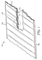
- FIG.1 shows a substantially flat filter element 1.0 comprising at least one filter media 12 having planarly disposed pleats 14 having folds 14a.
- the filter media 12 may be formed of a single material or a composite of multiple materials that are suitable alone or in combination to meet various filtration, structural support, drainage, and flow requirements of a chosen application.
- Such materials may include, for example, membranes (e.g., nylon, polyethersulfone, polytetrafluoroethylene, polypropylene, and the like), non-wovens, polymeric meshes, apertured films, fibrous media (typically made by a wet laid paper making type operation with materials such as, for example, glass fibers, diatomaceous earth, perlite, cellulose, and binder resins), non-fibrous media, depth filter media, adsorptive media, charge modified media, or any other material found to have beneficial characteristics for a given application and that can be configured in a substantially flat filter element.
- membranes e.g., nylon, polyethersulfone, polytetrafluoroethylene, polypropylene, and the like
- non-wovens e.g., polymeric meshes, apertured films
- fibrous media typically made by a wet laid paper making type operation with materials such as, for example, glass fibers, diatomaceous earth, perlite, cellulose, and binder resin
- the at least one filter media 12 may be formed of a single material.
- the filter media 12 may be formed of multiple materials.
- the at least one filter media 12 may be formed of multiple materials.
- the filter element 10 is formed in a non-rectangular configuration. It is envisioned that various shapes of filter elements 10 may be desired, depending on the needs of a particular application. Such varying shapes may be formed, for example, by punching or otherwise cutting them out of a larger article of filter media 12 or by pleating pre-shaped filter media 12. Although the shape shown in FIG. 1a is circular, other shapes can also be utilized.
- FIG. 1b is a detailed view of one possible configuration for planarly disposed pleats 14.
- the planarly disposed pleats 14 may be configured such that the crown 14c of a given pleat rests at or near the root 14b of a corresponding pleat.
- the planarly disposed pleats 14 may also be configured such that the crown 14c of a given pleat rests substantially against the leg 14d of a corresponding pleat in no specific relation to the root 14b of a corresponding pleat. It is envisioned that, in some embodiments, the planarly disposed pleats 14 may exhibit a combination of the above configurations or even a random assortment of pleat sizes.
- the resulting pleated filter element 10 may have one, three, five, seven, nine, eleven, thirteen or even fifteen layers of filter media at any given cross-section, each layer of filter media comprising either a single filter material or a composite of multiple filter materials.
- pleat refers to successive folds in a filter media forming first pleat legs having a first length and second pleat legs having a second length.
- Pleats may be formed with similar or dissimilar first and second leg lengths. Further, similar pleats may be uniformly distributed throughout a filter media or dissimilar pleats may be distributed in a repeating pattern or in an irregular or random pattern such that varying leg lengths are produced.
- the use of pleats in the filter media increases the amount of available surface area of the filter media in the filter device, and generally improves filter flow and throughput.
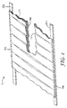
- the substantially flat filter element 10 could be manufactured either in discrete lengths for incorporation into a filtration application, wherein the at least one filter media 12 has a first end 12a and a second end 12b as shown in FIG. 4 , or in an essentially continuous form that be cut to length in a secondary operation.
- the substantially flat filter element 10 is welded along at least one edge 18a, 18b, each edge 18a, 18b being substantially parallel to the other and being substantially perpendicular to the folds 14a of the planarly disposed pleats 14.
- welding shall mean secured by any of various known polymer welding methods including, but not limited to, ultrasonic, high-frequency, vibration, friction, laser, solvent, contact, hot plate, plastic rod, speed tip, hot gas, and free hand.
- the folds 14a need not be perpendicular to edges 18a, 18b, such as where the filter element 10 is formed in a non-rectangular configuration. Where edges are welded, such welds may be substantially continuous, i.e., uninterrupted along the at least one edge 18a, 18b, or may be, for example, discrete tacks sufficient to hold each planarly disposed pleat 14 in a substantially flat configuration.
- the filter element 10 further comprises at least one substrate 20a that is further attached to the pleated filter media 12. Such at least one substrate 20a may be attached to the pleated filter media 12, for example, by welding, adhesives, stitching or any other attachment means defined in this application or suitable for the combination of materials employed.
- the at least one substrate 20a may comprise a polymeric material that can be welded to the filter media 12.
- the substrate 20a is non-permeable and is characterized as having a low water vapor transmission rate.
- non-permeable refers to a material that does not allow fluids to diffuse or pass through during reasonably expected operating conditions.
- water vapor transmission rate refers to the rate of water vapor transmission through the multilayer barrier composite as measured using the test described in ASTM F1249-01, (Standard Test Method for Water Vapor Transmission Rate Through Plastic Film and Sheeting Using a Modulated Infrared Sensor, Published December 2001), incorporated herein by reference.
- the substrate may comprise a single layer of material or may comprise multiple components, such as, for example, multilayer barrier composites.
- multilayer barrier composite refers to any combination of metal, plastic, or cellulosic layers (e.g., foils, films, and paper).
- the combination of metal, plastic, or cellulosic layers can include multiple layers of different materials, such as, for example, a metal combined with a plastic layer.
- the combination of metal, plastic, or cellulosic layers can also include multiple layers of similar materials, such as, for example, two layers of plastic.
- the layers can be combined substantially permanently using any processes known in the art, including, for example, coating, laminating, coextrusion, and deposition.
- Multilayer barrier films useful in the can comprise layers of low-density polyethylene, high-density polyethylene, polypropylene, polyester, and nylon. In some embodiments, a multilayer barrier film having a layer of metal, such as, for example, aluminum is used.
- an edge of the at least one substrate 20a extends beyond an edge 18a of the pleated filter media 12. In other embodiments, such as in FIG. 2 , an edge of the at least one substrate 20a is flush with an edge 18a of the pleated filter media 12. In embodiments where the at least one substrate 20a extends beyond an edge 18a of the pleated filter media12, a non-porous material for the at least one substrate 20a can be employed.It is envisioned that a second at least one substrate 20b may be attached to an opposite edge 18b of the pleated filter media 12, as shown in FIGS. 2 and 2a .
- such substrates 20a, 20b may be attached by same or different means, may comprise same or different materials, may each comprise an edge that is flush with an edge 18a, 18b of the pleated filter media 12, and may extend beyond an edge 18a, 18b of the pleated filter media 12 by same or different amounts, including embodiments where one substrate 20a or 20b is flush with an edge 18a, 18b of the pleated filter media 12 and a second substrate 20a or 20b extends beyond an edge 18a, 18b of the pleated filter media 12.
- a third substrate 20c may be further attached to one or both of the at least first and second substrates 20a, 20b.
- the third substrate 20c if employed, can be composed of a non-porous material.
- the third substrate 20c may be composed of a porous material configured to permit fluid flow therethrough.
- the third substrate 20c when employed, may be attached to the filter element 10 by any means discussed in this disclosure, or any other reasonable means known to those in the art consistent with the materials chosen and the applications desired. Such attachment means may be the same or different from any attachment means employed to secure substrates 20a and 20b to the filter element 10.
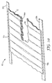
- the pleated filter media 12 may further, or alternatively, be provided with a framing substrate 34.
- the framing substrate 34 when provided, may allow for more robust attachment of the filter element 10 to another substrate or another article than would otherwise be attained when, for example, employing very porous or relatively fragile materials in filter media 12.
- the framing substrate 34 may provide varying degrees of rigidity to the filter element 10 for applications where a certain degree of structural stiffness is desired. In other embodiments, the framing substrate 34 may be configured to allow a high degree of flexibility of the filter element 10.
- At least a portion of the framing substrate 34 is attached directly to at least a portion of the pleated filter media 12. In other embodiments, at least a portion of the framing substrate 34 is attached to at least a portion of at least one substrate 20a, 20b, which may be directly attached to at least a portion of the pleated filter media 12. In still other embodiments, at least a portion of the framing substrate 34 is attached to at least a portion of a third substrate 20c, which is attached to at least one first or second substrate 20a, 20b, which may be directly attached to at least a portion of the pleated filter media 12. In appropriate applications and embodiments, the framing substrate 34 may be continuously or intermittently attached about a periphery 30 surrounding an operative filtration area 32.
- the framing substrate 34 may be composed of a single, continuous member. In other embodiments, a framing substrate 34 may be constructed of multiple members and subsequently assembled in a suitable framing configuration. Such a multiple-member framing substrate 34 may be, for example, easier or more efficient to manufacture, depending upon the capabilities of the fabrication means employed.
- the framing substrate 34 within the periphery 30, there may be a single aperture 36 or multiple apertures 36' enabling fluid communication through the framing substrate 34 to the pleated filter media 12.
- Such apertures 36 or 36' may be configured in a manner similar to a typical picture frame as in FIG. 4 , wherein four sides surround a single rectangular opening 36.
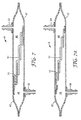
- the opening or openings in the framing substrate 34 may be, for example, circular in shape as in FIG. 4a or rectangular in shape as in FIG. 4b . It is also envisioned that there may be multiple openings of similar or different shapes in the framing substrate 34.
- openings in the framing substrate 34 comprise a mesh, for example, as may be provided with an extruded polymer mesh or an apertured film.
- a mesh for example, as may be provided with an extruded polymer mesh or an apertured film.
- Such mesh, or any combination of aperture or apertures may be configured with any reasonable porosity calculated or believed to provide suitable flow characteristics for the desired application.
- FIG. 5 is a partial cutaway view of a filter device before being assembled to encapsulate the filter element.
- the filter element 10 comprises at least one filter media 12 having planarly disposed pleats 14.
- the filter element 10 may be further attached to a framing substrate 34 and encapsulated between first and second non-permeable films 40, 42, respectively.
- the non-permeable films 40,42 shown in FIG. 5 are transparent, in other embodiments the films may be opaque.
- the non-permeable films may comprise a polymeric material that can be welded to other components of the filter device.
- the non-permeable film is characterized as having a low water vapor transmission rate.
- the non-permeable film may comprise a single layer of material or may comprise multiple components, such as, for example, multilayer barrier composites.
- multilayer barrier composite refers to any combination of metal, plastic, or cellulosic layers (e.g., foils, films, and paper).
- the combination of metal, plastic, or cellulosic layers can include multiple layers of different materials, such as, for example, a metal combined with a plastic layer.
- the combination of metal, plastic, or cellulosic layers can also include multiple layers of similar materials, such as, for example, two layers of plastic.
- the layers can be combined substantially permanently using any processes known in the art, including, for example, coating, laminating, coextrusion, and deposition.
- Multilayer barrier films useful in the can comprise layers of low-density polyethylene, high-density polyethylene, polypropylene, polyester, and nylon.
- a multilayer barrier film having a layer of metal, such as, for example, aluminum is used.
- at least one drainage substrate may further be provided. In such cases, the drainage substrate may be disposed in substantial contacting relation to either the filter media 12, the framing substrate 34, or both, though the drainage substrate need not be in contact with either to maintain function.
- FIG. 6 an exploded view of a filter device 8 illustrates one possible relative disposition of first non-permeable film 40, filter element 10 having a framing substrate 34, drainage substrate 52, and second non-permeable film 42. Dashes witness lines therein illustrate an example of desired attachment locations of the various components of the filter device 8. For example, in some embodiments, portions of the first non-permeable film 40 labeled "S" will attach to portions of the second non-permeable film 42 that are also labeled "S", and so on. It is to be understood that the exemplary attachment locations as illustrated in FIG. 7 represent only one possible assembly configuration for a filter device 8. The actual components selected, the physical disposition of those components, and relative attachment locations may vary depending on the materials selected and the desired application.
- FIG. 7 is a cross-sectional view of a filter device 8, not falling within the wording of the claims, having fluid communication ports 54, 56, and a filter element 10 comprising planarly disposed pleats 14.
- the filter element 10 is attached on one end to a first non-permeable film 40 and at the opposite end to a second non-permeable film 42.
- the first and second non-permeable films are sealed at their peripheries to create two chambers 44, 46 divided by the filter element 10.
- the first fluid communication port 54 is attached to the first non-permeable film 40 to create a fluid connection to the first chamber 44.
- the second fluid communication port 56 is attached to the second non-permeable film 42 to create a fluid connection to the second chamber 46.
- a source fluid enters the first fluid communication port 54, enters first chamber 44, passes through filter media 12 where it is filtered. The filtrate then enters second chamber 46 and exits the filter device 8 through the second communication port 56.
- the communication ports 54, 56 can be any design known in the art, and can be designed to allow multiple filter devices 8 to be connected directly to one another. In other embodiments, the communication ports are configured to connect to tubing. In some embodiments, the first and second communication ports are different and provide an operator aid in identifying which communication port is to be used as an inlet and which is an outlet. In some embodiments, the filter device 8 is designed to operate with either communication port being an inlet or outlet.
- FIG. 7a is a cross-sectional view of a filter device 8 having fluid communication ports 54, 56 and a filter element 10 comprising planarly disposed pleats 14 of filter media 12 attached to a framing substrate 34.
- the framing substrate 34 may be used to attach the filter element 10 to the first and second non-permeable films 40, 42.
- the use of a framing substrate 34 may facilitate handling of the filter media 12.
- the use of a framing substrate 34 may also assist in attaching the filter media 12 to the first and second non-permeable films 40, 42. If, for example, a filter media 12 is used that has multiple components, one surface of the filter media 12 may provide a better attachment anchor than the other. As shown in FIG.
- the framing substrate 34 is attached to one surface of the filter media 12.
- the framing substrate 34 shown in FIG. 7a also allows for the attachment interface of the filter element 10 to be in a compressive state during use. For example, if first fluid communication port 54 is used as an inlet, the first chamber 44 will operate at a higher pressure than the second chamber 46 because of the pressure drop caused by the filter media 10. Accordingly, the higher pressure of first chamber 44 will cause the filter media 10 to be compress against the framing substrate 34.
- FIG. 8 is an isometric cutaway view of a filter device, not falling within the wording of the claims, having fluid communication ports 54, 56, and a filter element 10 comprising a filter media 12 with planarly disposed pleats 14. As shown in FIG. 8 , the first and second non-permeable films 40, 42 are sealed at their peripheries to create two chambers 44, 46 divided by the filter element 10.
- FIGS. 9 and 9a are cross-sectional representations of filter devices, not falling within the wording of the claims, having multiple fluid communication ports 54, 54', 56, 56', two filter elements 10, 10', and a drainage substrate 52 disposed between the filter elements 10, 10'.
- the filter element 10 can comprise filter media 12 with planarly disposed pleats 14.
- the filter element can comprise planar filter media 12.
- the planar filter media 12 can comprise multiple pieces joined together as shown in FIG. 9a , or a single folded piece.
- two communication ports can be used to connect to each of the chambers 44, 46 to facilitate parallel filtration if multiple filter devices are employed.
- FIG. 10 shows a front and cross-sectional side view of an exemplary filter device 8.
- the filter device 8 comprises fluid communication ports 54 54', 56, 56' and a filter element 10 comprising planarly disposed pleats of filter media attached to a framing substrate 34.
- fluid communications ports 54 and 54' function as inlet ports
- fluid communication ports 56 and 56' function as outlet ports, relative to the filter element 10.
- the first and second non-permeable films are sealed at their peripheries to create two chambers 44, 46 divided by the filter element 10.
- a drainage substrate 52 is positioned in chamber 46 between the filter element 10 and the second non-permeable film 42.
- the differential pressure created by the filter element 10 may force the filter element 10 toward the second non-permeable film 42.
- the drainage substrate 52 is positioned between the filter element 10 and the second non-permeable film to help promote fluid flow from the filter element 10 toward the fluid communication ports 56, 56'.
- the fluid communication ports 54 may be configured to allow connection to additional filter devices 8.
- the fluid communication ports 54 may be designed to be male and female mating parts with integral seals, such as shown in FIG. 10 .
- the fluid communication ports 54 connected to one chamber form a single rigid body that extends from the first non-permeable film 40 to the second non-permeable film 42.
- the fluid communication port may comprise multiple pieces that are joined together with at least one fluid passage 48 that allow fluid flow from the fluid communication port 54 to the chambers 44.
- the use of a single rigid body may provide additional integrity in affixing the communication ports 54 to the first and second non-permeable films 40, 42.
- the use of a single rigid body may also provide improved handling capabilities when configuring the filter device for operation (e.g., connecting the communication ports).
- FIG. 11 is an exploded view of an apparatus 70 comprising stackable members 72 configured to contain at least one filter device 8.
- the apparatus 70 comprises a clamping device 76 having a first end wall 76a, a second end wall 76b, and clamping members 76c configured to draw the end walls 70a, 70b toward one another.
- the stackable members 72 have hangers 82 configured to accept the clamping members 76c to help support and locate the stackable members 72.
- Other clamping devices and stackable member positioning devices and methods may be employed, including for example, other known plate and frame assemblies.
- the clamping device can be any apparatus configured to hold a member and apply a compressive force thereto.
- suitable compressive forces include, but are not limited to, those provided by screws, hydraulic cylinders, pneumatic cylinders, cam levers, magnets, and gravity.
- the embodiment shown in FIG. 11 includes three filter devices 8 (similar to that shown in FIG. 10 ) located between four stackable members 72.
- the stackable members 72 are generally configured with a depressed area that provides a cavity when two stackable members are placed in intimate contact.
- the stackable member cavity is configured to provide mechanical support for the filter device 8.
- the stackable member cavity is configured to be slightly smaller than the outer geometry of the filter device 8 to eliminate any unsupported areas for the first and second non-permeable films 40, 42.
- the stackable members 72 can all be identical as shown in FIG. 11 , or can vary to accommodate different filter device 8 geometries.
- FIGS. 12 and 12a show an overhead view and a partial cross-section of one example of a stackable member 72 configured for use, for example, in the apparatus 70 shown in FIG. 11 .
- the stackable member 72 has a handle 84, hangers 82, a pressure port 88, a sealing member 78, and a cavity 86.
- the cavity 86 has apertures 90, 92 that are configured to accommodate the fluid communication ports of the filter device.
- the pressure port 88 is in fluid communication with cavity 86 and allows pressure and/or vacuum to be applied to the exterior of the filter device 8 within the cavity 86.
- the application of pressure to the exterior of the filter device can be used to promote evacuation of the filter device.
- the application of vacuum to the exterior of the filter device can be used to promote filling of the filter device.
- the sealing member 78 along with pressure port seal 96 create a fluid seal between the exterior surface of the filter device and atmosphere
- the pressure applied to the exterior of the filter device through pressure port 88 can be created with liquid or gas. In some embodiments, the liquid or gas can be introduced at a desired temperature.
- the stackable members can be made from any materials that can withstand the expected operating pressures, including metal in high pressure operations, and plastic in lower pressure operations. Since the stackable members are predominantly in a compressive state within the clamping device, plastic is suitable for many applications. In some embodiments, the stackable members are made from a transparent plastic that allows the operator to visually inspect the filter devices and related connections during operation.
- FIG. 13 is a detailed cross-section of one embodiment of an apparatus 70 configured to contain three filter devices 8 with arrows showing the general direction of fluid flow.
- the first end stackable member 72a has a first aperture 90 and a pressure port 88.
- a connection device 94 is used to extend the fluid communication port of the filter device beyond the stackable member 172a.
- the second end stackable member 72b Opposite the first end stackable member 72a, is the second end stackable member 72b.
- the second end stackable member 72b also has a connection device 94 associated with the opposite fluid communication port of the filter device.
- the filter devices can be configured for parallel flow.
- the fluid communication ports of the filter device are configured for serial flow.
- the fluid communication ports are configured such that change parts can be inserted to change the communication port of a filter device from a parallel configuration to a serial configuration and vice versa. This can be accomplished, for example, by inserting or removing a plug in the fluid communication port.
- a combination of serial and parallel flow is used for the various filter devices (i.e., a quantity of the filter devices are used for parallel flow, and the remaining quantity of the filter devices are subject to serial flow).
- the filter devices typically have different types of filter media and filtration requirements. For example, a series of filter devices with depth media may be subjected to parallel flow followed by a filter device with a membrane filter media connected in series.
- the filter devices are configured to support tangential flow filtration.
- two fluid communication ports are in fluid communication with at least one of the chambers and are separated from each other such that the source fluid needs to travel along a length of the filter media (i.e., tangential flow).
- filter media of the filter device described can be replaced with a suitable cell growth media.
- the filter device can thus become a cell growth device.
- the cell growth device provides an apparatus for maintaining a controlled environment for the growth of cells.
- multiple cell growth devices are interconnected by multiple fluid inlet and outlet ports to provide the necessary liquid and gas exchange required for optimum cell growth.
- the individual cell growth devices can be further sealed by a chamber formed by multiple rigid stackable members that may direct a positive or negative fluid pressure, for example, via pressure port similar to pressure port 88, to the outer film walls of the film enclosures of the cell growth device.
- the compressive and expansion effect on the films walls can create either a directional fluid flow through the cell growth substrate or a rise and fall of the liquid/gas interface across the surface of the cell growth substrate within the cell growth device.
- the action of compressing or expanding the outer cell growth device walls allows for the controlled rise or fall of the fluid within the cell growth device.
- the use of valves, including, for example check valves, at up and/or down stream fluid locations allows directional fluid flow to be achieved.
- a combination of cell growth devices and filter devices are configured in stackable members such that both cell growth and filtration can be accomplished within a single apparatus.
- cell growth fluid is periodically moved from at least one of the filter devices to at least one of the cell growth devices.
- Valves are used to control the direction and flow of fluids in accordance with the desired protocol.
- waste product may be removed and/or nutrients may be added during the process.
- a third expandable device for fluid storage is used that is neither a cell growth device nor a filter device. This third type of device can be used as a temporary storage unit for fluid when rotating fluids between devices in the apparatus (i.e., exchanging fluid in a cell growth device with fluid in a filter device) or adjusting cell growth fluid levels within the cell growth devices.
Landscapes
- Chemical & Material Sciences (AREA)
- Chemical Kinetics & Catalysis (AREA)
- Separation Using Semi-Permeable Membranes (AREA)
- Filtering Materials (AREA)
- Filtering Of Dispersed Particles In Gases (AREA)
Applications Claiming Priority (2)
| Application Number | Priority Date | Filing Date | Title |
|---|---|---|---|
| US1614907P | 2007-12-21 | 2007-12-21 | |
| PCT/US2008/086923 WO2009085726A1 (en) | 2007-12-21 | 2008-12-16 | Filter device |
Publications (3)
| Publication Number | Publication Date |
|---|---|
| EP2231300A1 EP2231300A1 (en) | 2010-09-29 |
| EP2231300A4 EP2231300A4 (en) | 2011-05-04 |
| EP2231300B1 true EP2231300B1 (en) | 2013-12-11 |
Family
ID=40824645
Family Applications (1)
| Application Number | Title | Priority Date | Filing Date |
|---|---|---|---|
| EP08867451.0A Not-in-force EP2231300B1 (en) | 2007-12-21 | 2008-12-16 | Filter device |
Country Status (5)
| Country | Link |
|---|---|
| US (3) | US20110226691A1 (enExample) |
| EP (1) | EP2231300B1 (enExample) |
| JP (1) | JP2011507686A (enExample) |
| CN (1) | CN101918102B (enExample) |
| WO (1) | WO2009085726A1 (enExample) |
Families Citing this family (21)
| Publication number | Priority date | Publication date | Assignee | Title |
|---|---|---|---|---|
| US20060108277A1 (en) | 2004-11-19 | 2006-05-25 | Fall Brian L | Circumferentially pleated filter assembly and method of forming the same |
| US8545658B2 (en) | 2005-11-09 | 2013-10-01 | 3M Innovative Properties Company | Apparatus and methods for forming filter sleeves having circumferential pleats for use in a bag-type filter assembly |
| EP2231300B1 (en) | 2007-12-21 | 2013-12-11 | 3M Innovative Properties Company | Filter device |
| EP2522692B1 (en) | 2008-05-30 | 2014-06-18 | 3M Innovative Properties Company | Ligand monomers and copolymers made therewith |
| BRPI0923565A2 (pt) | 2008-12-23 | 2016-01-26 | 3M Innovative Properties Co | artigo não tecido funcionalizado |
| BRPI1011747A2 (pt) | 2009-06-23 | 2018-02-27 | 3M Innovative Properties Co | artigo não tecido funcionalizado. |
| US8377672B2 (en) | 2010-02-18 | 2013-02-19 | 3M Innovative Properties Company | Ligand functionalized polymers |
| EP2889625B1 (en) | 2010-03-03 | 2016-09-14 | 3M Innovative Properties Company | Ligand guanidinyl functionalized polymers |
| US8851296B2 (en) * | 2010-09-21 | 2014-10-07 | Asahi Kasei Medical Co., Ltd. | Blood processing filter and the method for manufacturing the same |
| BR112014006465B1 (pt) * | 2011-09-19 | 2021-03-30 | 3M Innovative Properties Company | Cápsula de filtração |
| WO2015023468A1 (en) | 2013-08-15 | 2015-02-19 | 3M Innovative Properties Company | Filter element and filtration assembly for biopharmaceutical applications |
| KR101564759B1 (ko) * | 2014-02-04 | 2015-11-02 | 한국과학기술연구원 | 막 증류 수처리 용 분리막 |
| US20160158704A1 (en) * | 2014-12-05 | 2016-06-09 | Rorus Inc. | Method for Manufacturing a Fluid Purification Device |
| JP6637998B2 (ja) * | 2015-05-08 | 2020-01-29 | イー・エム・デイー・ミリポア・コーポレイシヨン | フィルム結合型フラットパック |
| DE102016005157A1 (de) * | 2015-05-22 | 2016-11-24 | Mann + Hummel Gmbh | Filtereinsatz für ein Fluid, insbesondere Getriebeöl |
| US20170216742A1 (en) * | 2016-02-03 | 2017-08-03 | Parker-Hannifin Corporation | Inline insert molded filter assembly |
| US20190329160A1 (en) * | 2018-04-26 | 2019-10-31 | Frederick Halliday | Filter Medium Having a Sealing Portion |
| US20210387119A1 (en) * | 2018-10-23 | 2021-12-16 | Teijin Limited | Filtration filter, filter-equipped container, and method for removing foreign matter in cell suspension |
| US10688417B2 (en) * | 2018-10-24 | 2020-06-23 | Pall Corporation | Support and drainage material, filter, and method of use |
| DE102019001309A1 (de) * | 2019-02-23 | 2020-08-27 | Hydac Filtertechnik Gmbh | Filtervorrichtung |
| DE102024001154A1 (de) * | 2024-04-10 | 2025-10-16 | Hydac Filtertechnik Gmbh | Einrichtung |
Family Cites Families (84)
| Publication number | Priority date | Publication date | Assignee | Title |
|---|---|---|---|---|
| US624014A (en) | 1899-05-02 | The norris peters cd | ||
| US1647799A (en) * | 1926-03-05 | 1927-11-01 | Forrester L Hammer | Strainer |
| US1846584A (en) * | 1928-03-09 | 1932-02-23 | John W Clark | Wrapper for packages, bales, and the like |
| US1809716A (en) * | 1929-04-20 | 1931-06-09 | Lawrence E Mcdonough | Plaiting machine |
| US2323896A (en) * | 1940-11-06 | 1943-07-13 | Mutual Machine Company | Selective plaiting machine |
| US2387368A (en) * | 1942-02-26 | 1945-10-23 | Vokes Cecil Gordon | Filter for liquids or gases |
| US2395449A (en) * | 1942-03-31 | 1946-02-26 | Southwick W Briggs | Filter unit |
| US2420414A (en) * | 1943-09-21 | 1947-05-13 | Southwick W Briggs | Filter construction |
| US2448157A (en) * | 1945-09-01 | 1948-08-31 | Max S Schneider | Portable filter |
| US2586078A (en) * | 1946-06-19 | 1952-02-19 | American Viscose Corp | Method and means for packaging |
| US2689652A (en) * | 1950-11-04 | 1954-09-21 | Gen Motors Corp | Oil filter |
| US2758760A (en) * | 1953-11-06 | 1956-08-14 | Bock Franz | Machine for producing accordion pleating |
| US2792118A (en) * | 1953-11-24 | 1957-05-14 | Jr Frederick Kraissl | Strainers |
| US2801009A (en) * | 1954-02-10 | 1957-07-30 | Gen Motors Corp | Filter having outwardly extending pleats |
| US2840283A (en) * | 1955-10-25 | 1958-06-24 | Roussos Mary | Method of plaiting and apparatus for the practice of such method |
| GB823648A (en) | 1956-09-27 | 1959-11-18 | Air Maze Corp | Filters for fluids |
| US3106528A (en) * | 1957-03-25 | 1963-10-08 | Roland H Burks | Filter cartridge and method and means for making the same |
| US2979240A (en) * | 1959-07-06 | 1961-04-11 | Ideal Pleating Company | Pleating apparatus and method |
| DE1118758B (de) | 1959-11-05 | 1961-12-07 | Fr August Neidig Soehne Maschi | Fluessigkeitsfilter mit zylindrischem Filtereinsatz |
| US3306794A (en) | 1963-02-12 | 1967-02-28 | Wix Corp | Method of making a filter element |
| US3390218A (en) * | 1964-10-06 | 1968-06-25 | Johnson & Johnson | Method of pleating sheet materials |
| US3349159A (en) * | 1964-08-31 | 1967-10-24 | Luboshez Sergius N Ferris | Method and apparatus for pleating material |
| US3542636A (en) * | 1965-07-28 | 1970-11-24 | Kurt Wandel | Corrugated board |
| US3474599A (en) * | 1968-01-04 | 1969-10-28 | Louis Schwab | Filter assemblage for purifying a particle-laden gaseous flow |
| US3733267A (en) * | 1970-04-17 | 1973-05-15 | Taussig Frederick | Process of filtration of dry cleaning fluid |
| US3701433A (en) * | 1970-11-10 | 1972-10-31 | Pall Corp | Filter for use in the filtration of blood |
| GB1400147A (en) | 1971-08-26 | 1975-07-16 | Rolls Royce | Filter elements |
| GB1481050A (en) * | 1973-10-30 | 1977-07-27 | Mitsubishi Petrochemical Co | Corrugated cardboard sheet and method for producing the same |
| JPS544121Y2 (enExample) * | 1974-07-05 | 1979-02-23 | ||
| US3988244A (en) * | 1975-06-30 | 1976-10-26 | Sta-Rite Industries, Inc. | Cartridge filter |
| US4081379A (en) * | 1976-10-28 | 1978-03-28 | Advanced Filtration Equipment Corporation | Filter bag arrangement for a pressure vessel and method of manufacture thereof |
| US4136029A (en) * | 1978-03-24 | 1979-01-23 | Carl Schleicher & Schull | Pressure filtration device |
| GB2035893B (en) * | 1978-12-05 | 1982-08-04 | Roldwest Ltd | Pleating and laminating |
| US4422939A (en) * | 1979-11-07 | 1983-12-27 | Texas Medical Products, Inc. | Blood and perfusate filter |
| US4552661A (en) * | 1981-10-16 | 1985-11-12 | Morgan Howard W | Liquid filter having self-retaining filter bags |
| US4465213A (en) * | 1981-12-22 | 1984-08-14 | Karl Rabofsky Gmbh | Pleating machine |
| CA1182758A (en) * | 1983-12-09 | 1985-02-19 | Anthony N. Sharpe | Apparatus for filtration |
| JPS60125220A (ja) | 1983-12-13 | 1985-07-04 | Tsuchiya Mfg Co Ltd | 炉過エレメントの製造法 |
| DE3578502D1 (de) * | 1984-03-15 | 1990-08-09 | Asahi Medical Co | Filtereinheit zum abtrennen von leukozyten. |
| JPS6197003A (ja) * | 1984-10-19 | 1986-05-15 | Jun Taga | カ−トリツジフイルタ− |
| GB2176416B (en) * | 1985-06-08 | 1989-07-26 | Sartorius Gmbh | Fluid filter |
| US4828698A (en) * | 1986-03-07 | 1989-05-09 | Pall Corporation | Filtering apparatus |
| FR2595666B1 (fr) * | 1986-03-17 | 1988-05-13 | Capy Gilbert | Emballage pour forme convexe obtenu a partir d'une feuille mince plissee |
| GB2189403B (en) * | 1986-04-21 | 1989-11-29 | Steetley Refractories Ltd | Method of and apparatus for filtering a slurry |
| US4877526A (en) * | 1987-08-31 | 1989-10-31 | Minnesota Mining And Manufacturing Company | Flexible filter bag and method of fabrication |
| US4863602A (en) * | 1987-08-31 | 1989-09-05 | Minnesota Mining And Manufacturing Company | Flexible filter element employing filtering sheets formed with bypass openings |
| US5252207A (en) * | 1988-06-15 | 1993-10-12 | Pall Corporation | Wrap member having openings |
| DE3905854A1 (de) | 1989-02-24 | 1990-09-20 | Brieden Karl Bau Beteiligung | Spaltfilterkerze |
| WO1990015660A1 (fr) * | 1989-06-13 | 1990-12-27 | Atsunobu Sakamoto | Filtre en forme de sac |
| SU1761201A1 (ru) | 1990-06-07 | 1992-09-15 | Научно-исследовательский институт полупроводникового машиностроения | Фильтрующий элемент |
| US5174896A (en) * | 1990-06-25 | 1992-12-29 | Harmsco, Inc. | Filtering system utilizing rotational flow and angled pleated filter media and method for making slanted pleated filter media |
| US5075004A (en) * | 1990-10-23 | 1991-12-24 | Isp Investments Inc. | Filter bag seal |
| US5104536A (en) * | 1991-02-22 | 1992-04-14 | Gelman Sciences, Inc. | Polymeric film filter assembly |
| US5200073A (en) * | 1991-02-22 | 1993-04-06 | Gelman Sciences Inc. | Polymeric film filter assembly |
| US5275743A (en) * | 1991-12-10 | 1994-01-04 | Pall Corporation | Filter and filtration method |
| US5211091A (en) * | 1992-07-02 | 1993-05-18 | Purolator Products Company | Pleat pack cutter |
| US5543047A (en) * | 1992-11-06 | 1996-08-06 | Pall Corporation | Filter with over-laid pleats in intimate contact |
| CN1067291C (zh) | 1992-11-06 | 2001-06-20 | 帕尔公司 | 过滤器 |
| US5342511A (en) * | 1993-07-06 | 1994-08-30 | Baldwin Filters, Inc. | Oil filter with inner and outer coaxial filter elements |
| US5403482A (en) * | 1993-10-12 | 1995-04-04 | Gelman Sciences Inc. | Self-supporting, pleated, spirally wound filter and the corresponding process of making |
| US5709771A (en) * | 1994-08-30 | 1998-01-20 | Cellular Designs Unlimited, Inc. | Method and apparatus for forming an expandable-collapsible article having a contoured surface |
| CN1068795C (zh) * | 1995-04-21 | 2001-07-25 | 唐纳森公司 | 褶皱式过滤器制造方法 |
| US5702037A (en) * | 1995-06-01 | 1997-12-30 | Merkel; Ronald F. | Pleating machine and method |
| US5685985A (en) * | 1995-12-20 | 1997-11-11 | Baldwin Filters, Inc. | Environmentally friendly filter cartridge |
| BR9806721A (pt) * | 1997-01-20 | 2000-04-04 | Cuno Inc | Aparelho e método compreendendo etapas para formação de cartuchos de filtro pregueado helicoidal |
| US6511598B2 (en) * | 1997-09-02 | 2003-01-28 | Moshe Gershenson | Concentrically arranged filter element assembly |
| US6030531A (en) * | 1997-09-02 | 2000-02-29 | Gershenson; Moshe | Filter element assembly |
| US6871480B1 (en) * | 1997-09-29 | 2005-03-29 | David P. Goodrich | Pleated paper and method of manufacturing |
| US5840188A (en) * | 1997-10-21 | 1998-11-24 | Le Sac Corporation | Snap fit filter bag assembly |
| EP1140319B1 (en) * | 1999-01-07 | 2005-06-29 | Cuno Incorporated | Pleated filter element and method of forming a pleated filter element |
| DE19941029C2 (de) * | 1999-08-28 | 2001-07-26 | Freudenberg Carl Fa | Filtereinsatz aus einem zickzackförmig gefalteten Faltenpack und Verfahren zu seiner Herstellung |
| US6709412B2 (en) * | 1999-09-03 | 2004-03-23 | Baxter International Inc. | Blood processing systems and methods that employ an in-line leukofilter mounted in a restraining fixture |
| CA2385319A1 (en) | 1999-09-22 | 2001-03-29 | Pall Corporation | Filter elements and filtering methods |
| AU2045001A (en) * | 1999-11-23 | 2001-06-04 | Pall Corporation | Conductive filter cartridge |
| US6409919B1 (en) * | 2001-01-23 | 2002-06-25 | North American Filter Corporation | Reusable filter housing with replaceable, disposable filter cartridge |
| US6780217B1 (en) * | 2002-07-31 | 2004-08-24 | Dana Corporation | Panel air filter with gasket of non-woven felt |
| US20040075221A1 (en) * | 2002-08-15 | 2004-04-22 | Moshe Gershenson | Inlet flange and seal for a collapsible filter element |
| US6872309B2 (en) * | 2002-10-04 | 2005-03-29 | Hayward Filtration, Llc | Filter bag assembly |
| JP2005087930A (ja) * | 2003-09-19 | 2005-04-07 | Kyosan Denki Co Ltd | 濾過装置 |
| US20050279695A1 (en) * | 2004-06-17 | 2005-12-22 | Millipore Corporation | Disposable integral filter unit |
| US20060108277A1 (en) * | 2004-11-19 | 2006-05-25 | Fall Brian L | Circumferentially pleated filter assembly and method of forming the same |
| US20070084786A1 (en) * | 2005-10-14 | 2007-04-19 | General Electric Company | Filter, filter media, and methods for making same |
| US8545658B2 (en) * | 2005-11-09 | 2013-10-01 | 3M Innovative Properties Company | Apparatus and methods for forming filter sleeves having circumferential pleats for use in a bag-type filter assembly |
| EP2231300B1 (en) | 2007-12-21 | 2013-12-11 | 3M Innovative Properties Company | Filter device |
-
2008
- 2008-12-16 EP EP08867451.0A patent/EP2231300B1/en not_active Not-in-force
- 2008-12-16 CN CN2008801250897A patent/CN101918102B/zh not_active Expired - Fee Related
- 2008-12-16 WO PCT/US2008/086923 patent/WO2009085726A1/en not_active Ceased
- 2008-12-16 JP JP2010539689A patent/JP2011507686A/ja active Pending
- 2008-12-16 US US12/809,194 patent/US20110226691A1/en not_active Abandoned
-
2013
- 2013-01-04 US US13/734,557 patent/US9038830B2/en not_active Expired - Fee Related
-
2015
- 2015-02-25 US US14/631,048 patent/US20150165349A1/en not_active Abandoned
Also Published As
| Publication number | Publication date |
|---|---|
| CN101918102A (zh) | 2010-12-15 |
| US9038830B2 (en) | 2015-05-26 |
| US20150165349A1 (en) | 2015-06-18 |
| US20110226691A1 (en) | 2011-09-22 |
| CN101918102B (zh) | 2013-09-11 |
| EP2231300A4 (en) | 2011-05-04 |
| WO2009085726A1 (en) | 2009-07-09 |
| EP2231300A1 (en) | 2010-09-29 |
| JP2011507686A (ja) | 2011-03-10 |
| US20130199985A1 (en) | 2013-08-08 |
Similar Documents
| Publication | Publication Date | Title |
|---|---|---|
| EP2231300B1 (en) | Filter device | |
| KR101829293B1 (ko) | 나선형 직교류 필터 | |
| US5723047A (en) | Compressible filter element peripherally sealed by a settable material | |
| WO1998030308A1 (en) | Filtration cassette article and filter comprising same | |
| AU2014388298B2 (en) | Biological fluid filters with molded frame and methods for making such filters | |
| US6527954B1 (en) | Layered bag filter elements | |
| EP1732660A1 (en) | Pleated, crossflow fluid treatment elements | |
| JPH08332306A (ja) | 脱気用膜及び脱気モジュール | |
| EP3568224A1 (en) | Method of manufacturing a fluid filter | |
| JPWO2007122909A1 (ja) | プリーツ型フィルタカートリッジ | |
| US5401403A (en) | Membrane module and a method for its manufacture | |
| US4304669A (en) | Device for the mass transfer between fluids | |
| JPS6061018A (ja) | 濾過装置 | |
| JP4227687B2 (ja) | 中空糸膜モジュール | |
| KR20160030107A (ko) | 나선형 교류 필터 | |
| KR870000603B1 (ko) | 여과 장치 | |
| JPH06342A (ja) | 中空糸膜モジュール及びその組立体 | |
| JP2003181227A (ja) | フィルタカートリッジ | |
| RU2171133C2 (ru) | Мембранное устройство | |
| EP3294207B1 (en) | Film bonded flatpack | |
| JPS6014902A (ja) | 濾過装置 | |
| GB2306897A (en) | Filter with flowable, settable sealant | |
| JPH03207416A (ja) | 濾過体 | |
| JPH08323159A (ja) | 濾過ユニットとこれを用いた濾過モジュール |
Legal Events
| Date | Code | Title | Description |
|---|---|---|---|
| PUAI | Public reference made under article 153(3) epc to a published international application that has entered the european phase |
Free format text: ORIGINAL CODE: 0009012 |
|
| 17P | Request for examination filed |
Effective date: 20100721 |
|
| AK | Designated contracting states |
Kind code of ref document: A1 Designated state(s): AT BE BG CH CY CZ DE DK EE ES FI FR GB GR HR HU IE IS IT LI LT LU LV MC MT NL NO PL PT RO SE SI SK TR |
|
| AX | Request for extension of the european patent |
Extension state: AL BA MK RS |
|
| DAX | Request for extension of the european patent (deleted) | ||
| A4 | Supplementary search report drawn up and despatched |
Effective date: 20110405 |
|
| 17Q | First examination report despatched |
Effective date: 20111129 |
|
| GRAP | Despatch of communication of intention to grant a patent |
Free format text: ORIGINAL CODE: EPIDOSNIGR1 |
|
| INTG | Intention to grant announced |
Effective date: 20130725 |
|
| GRAS | Grant fee paid |
Free format text: ORIGINAL CODE: EPIDOSNIGR3 |
|
| GRAA | (expected) grant |
Free format text: ORIGINAL CODE: 0009210 |
|
| AK | Designated contracting states |
Kind code of ref document: B1 Designated state(s): AT BE BG CH CY CZ DE DK EE ES FI FR GB GR HR HU IE IS IT LI LT LU LV MC MT NL NO PL PT RO SE SI SK TR |
|
| REG | Reference to a national code |
Ref country code: GB Ref legal event code: FG4D |
|
| REG | Reference to a national code |
Ref country code: CH Ref legal event code: EP |
|
| REG | Reference to a national code |
Ref country code: AT Ref legal event code: REF Ref document number: 644168 Country of ref document: AT Kind code of ref document: T Effective date: 20140115 |
|
| REG | Reference to a national code |
Ref country code: IE Ref legal event code: FG4D |
|
| REG | Reference to a national code |
Ref country code: DE Ref legal event code: R096 Ref document number: 602008029321 Country of ref document: DE Effective date: 20140206 |
|
| REG | Reference to a national code |
Ref country code: NL Ref legal event code: VDEP Effective date: 20131211 |
|
| REG | Reference to a national code |
Ref country code: AT Ref legal event code: MK05 Ref document number: 644168 Country of ref document: AT Kind code of ref document: T Effective date: 20131211 |
|
| PG25 | Lapsed in a contracting state [announced via postgrant information from national office to epo] |
Ref country code: FI Free format text: LAPSE BECAUSE OF FAILURE TO SUBMIT A TRANSLATION OF THE DESCRIPTION OR TO PAY THE FEE WITHIN THE PRESCRIBED TIME-LIMIT Effective date: 20131211 Ref country code: LT Free format text: LAPSE BECAUSE OF FAILURE TO SUBMIT A TRANSLATION OF THE DESCRIPTION OR TO PAY THE FEE WITHIN THE PRESCRIBED TIME-LIMIT Effective date: 20131211 Ref country code: NL Free format text: LAPSE BECAUSE OF FAILURE TO SUBMIT A TRANSLATION OF THE DESCRIPTION OR TO PAY THE FEE WITHIN THE PRESCRIBED TIME-LIMIT Effective date: 20131211 Ref country code: HR Free format text: LAPSE BECAUSE OF FAILURE TO SUBMIT A TRANSLATION OF THE DESCRIPTION OR TO PAY THE FEE WITHIN THE PRESCRIBED TIME-LIMIT Effective date: 20131211 Ref country code: SE Free format text: LAPSE BECAUSE OF FAILURE TO SUBMIT A TRANSLATION OF THE DESCRIPTION OR TO PAY THE FEE WITHIN THE PRESCRIBED TIME-LIMIT Effective date: 20131211 Ref country code: NO Free format text: LAPSE BECAUSE OF FAILURE TO SUBMIT A TRANSLATION OF THE DESCRIPTION OR TO PAY THE FEE WITHIN THE PRESCRIBED TIME-LIMIT Effective date: 20140311 |
|
| REG | Reference to a national code |
Ref country code: LT Ref legal event code: MG4D |
|
| PG25 | Lapsed in a contracting state [announced via postgrant information from national office to epo] |
Ref country code: AT Free format text: LAPSE BECAUSE OF FAILURE TO SUBMIT A TRANSLATION OF THE DESCRIPTION OR TO PAY THE FEE WITHIN THE PRESCRIBED TIME-LIMIT Effective date: 20131211 Ref country code: LV Free format text: LAPSE BECAUSE OF FAILURE TO SUBMIT A TRANSLATION OF THE DESCRIPTION OR TO PAY THE FEE WITHIN THE PRESCRIBED TIME-LIMIT Effective date: 20131211 Ref country code: CY Free format text: LAPSE BECAUSE OF FAILURE TO SUBMIT A TRANSLATION OF THE DESCRIPTION OR TO PAY THE FEE WITHIN THE PRESCRIBED TIME-LIMIT Effective date: 20131211 |
|
| PG25 | Lapsed in a contracting state [announced via postgrant information from national office to epo] |
Ref country code: BE Free format text: LAPSE BECAUSE OF FAILURE TO SUBMIT A TRANSLATION OF THE DESCRIPTION OR TO PAY THE FEE WITHIN THE PRESCRIBED TIME-LIMIT Effective date: 20131211 Ref country code: IS Free format text: LAPSE BECAUSE OF FAILURE TO SUBMIT A TRANSLATION OF THE DESCRIPTION OR TO PAY THE FEE WITHIN THE PRESCRIBED TIME-LIMIT Effective date: 20140411 Ref country code: EE Free format text: LAPSE BECAUSE OF FAILURE TO SUBMIT A TRANSLATION OF THE DESCRIPTION OR TO PAY THE FEE WITHIN THE PRESCRIBED TIME-LIMIT Effective date: 20131211 |
|
| REG | Reference to a national code |
Ref country code: CH Ref legal event code: PL |
|
| PG25 | Lapsed in a contracting state [announced via postgrant information from national office to epo] |
Ref country code: PT Free format text: LAPSE BECAUSE OF FAILURE TO SUBMIT A TRANSLATION OF THE DESCRIPTION OR TO PAY THE FEE WITHIN THE PRESCRIBED TIME-LIMIT Effective date: 20140411 Ref country code: PL Free format text: LAPSE BECAUSE OF FAILURE TO SUBMIT A TRANSLATION OF THE DESCRIPTION OR TO PAY THE FEE WITHIN THE PRESCRIBED TIME-LIMIT Effective date: 20131211 Ref country code: SK Free format text: LAPSE BECAUSE OF FAILURE TO SUBMIT A TRANSLATION OF THE DESCRIPTION OR TO PAY THE FEE WITHIN THE PRESCRIBED TIME-LIMIT Effective date: 20131211 Ref country code: CZ Free format text: LAPSE BECAUSE OF FAILURE TO SUBMIT A TRANSLATION OF THE DESCRIPTION OR TO PAY THE FEE WITHIN THE PRESCRIBED TIME-LIMIT Effective date: 20131211 Ref country code: ES Free format text: LAPSE BECAUSE OF FAILURE TO SUBMIT A TRANSLATION OF THE DESCRIPTION OR TO PAY THE FEE WITHIN THE PRESCRIBED TIME-LIMIT Effective date: 20131211 Ref country code: RO Free format text: LAPSE BECAUSE OF FAILURE TO SUBMIT A TRANSLATION OF THE DESCRIPTION OR TO PAY THE FEE WITHIN THE PRESCRIBED TIME-LIMIT Effective date: 20131211 |
|
| REG | Reference to a national code |
Ref country code: DE Ref legal event code: R097 Ref document number: 602008029321 Country of ref document: DE |
|
| REG | Reference to a national code |
Ref country code: IE Ref legal event code: MM4A |
|
| PG25 | Lapsed in a contracting state [announced via postgrant information from national office to epo] |
Ref country code: MC Free format text: LAPSE BECAUSE OF FAILURE TO SUBMIT A TRANSLATION OF THE DESCRIPTION OR TO PAY THE FEE WITHIN THE PRESCRIBED TIME-LIMIT Effective date: 20131211 |
|
| PLBE | No opposition filed within time limit |
Free format text: ORIGINAL CODE: 0009261 |
|
| STAA | Information on the status of an ep patent application or granted ep patent |
Free format text: STATUS: NO OPPOSITION FILED WITHIN TIME LIMIT |
|
| PG25 | Lapsed in a contracting state [announced via postgrant information from national office to epo] |
Ref country code: IE Free format text: LAPSE BECAUSE OF NON-PAYMENT OF DUE FEES Effective date: 20131216 Ref country code: DK Free format text: LAPSE BECAUSE OF FAILURE TO SUBMIT A TRANSLATION OF THE DESCRIPTION OR TO PAY THE FEE WITHIN THE PRESCRIBED TIME-LIMIT Effective date: 20131211 Ref country code: CH Free format text: LAPSE BECAUSE OF NON-PAYMENT OF DUE FEES Effective date: 20131231 Ref country code: LI Free format text: LAPSE BECAUSE OF NON-PAYMENT OF DUE FEES Effective date: 20131231 |
|
| 26N | No opposition filed |
Effective date: 20140912 |
|
| GBPC | Gb: european patent ceased through non-payment of renewal fee |
Effective date: 20140311 |
|
| REG | Reference to a national code |
Ref country code: DE Ref legal event code: R097 Ref document number: 602008029321 Country of ref document: DE Effective date: 20140912 |
|
| REG | Reference to a national code |
Ref country code: FR Ref legal event code: ST Effective date: 20141124 |
|
| PG25 | Lapsed in a contracting state [announced via postgrant information from national office to epo] |
Ref country code: FR Free format text: LAPSE BECAUSE OF NON-PAYMENT OF DUE FEES Effective date: 20140211 Ref country code: GB Free format text: LAPSE BECAUSE OF NON-PAYMENT OF DUE FEES Effective date: 20140311 |
|
| PG25 | Lapsed in a contracting state [announced via postgrant information from national office to epo] |
Ref country code: SI Free format text: LAPSE BECAUSE OF FAILURE TO SUBMIT A TRANSLATION OF THE DESCRIPTION OR TO PAY THE FEE WITHIN THE PRESCRIBED TIME-LIMIT Effective date: 20131211 |
|
| PG25 | Lapsed in a contracting state [announced via postgrant information from national office to epo] |
Ref country code: TR Free format text: LAPSE BECAUSE OF FAILURE TO SUBMIT A TRANSLATION OF THE DESCRIPTION OR TO PAY THE FEE WITHIN THE PRESCRIBED TIME-LIMIT Effective date: 20131211 |
|
| PG25 | Lapsed in a contracting state [announced via postgrant information from national office to epo] |
Ref country code: BG Free format text: LAPSE BECAUSE OF FAILURE TO SUBMIT A TRANSLATION OF THE DESCRIPTION OR TO PAY THE FEE WITHIN THE PRESCRIBED TIME-LIMIT Effective date: 20131211 Ref country code: LU Free format text: LAPSE BECAUSE OF NON-PAYMENT OF DUE FEES Effective date: 20131216 Ref country code: HU Free format text: LAPSE BECAUSE OF FAILURE TO SUBMIT A TRANSLATION OF THE DESCRIPTION OR TO PAY THE FEE WITHIN THE PRESCRIBED TIME-LIMIT; INVALID AB INITIO Effective date: 20081216 |
|
| PG25 | Lapsed in a contracting state [announced via postgrant information from national office to epo] |
Ref country code: IT Free format text: LAPSE BECAUSE OF FAILURE TO SUBMIT A TRANSLATION OF THE DESCRIPTION OR TO PAY THE FEE WITHIN THE PRESCRIBED TIME-LIMIT Effective date: 20131211 Ref country code: GR Free format text: LAPSE BECAUSE OF NON-PAYMENT OF DUE FEES Effective date: 20131211 Ref country code: MT Free format text: LAPSE BECAUSE OF FAILURE TO SUBMIT A TRANSLATION OF THE DESCRIPTION OR TO PAY THE FEE WITHIN THE PRESCRIBED TIME-LIMIT Effective date: 20131211 |
|
| PGFP | Annual fee paid to national office [announced via postgrant information from national office to epo] |
Ref country code: DE Payment date: 20151208 Year of fee payment: 8 |
|
| PG25 | Lapsed in a contracting state [announced via postgrant information from national office to epo] |
Ref country code: GR Free format text: LAPSE BECAUSE OF FAILURE TO SUBMIT A TRANSLATION OF THE DESCRIPTION OR TO PAY THE FEE WITHIN THE PRESCRIBED TIME-LIMIT Effective date: 20140312 |
|
| REG | Reference to a national code |
Ref country code: DE Ref legal event code: R119 Ref document number: 602008029321 Country of ref document: DE |
|
| PG25 | Lapsed in a contracting state [announced via postgrant information from national office to epo] |
Ref country code: DE Free format text: LAPSE BECAUSE OF NON-PAYMENT OF DUE FEES Effective date: 20170701 |