EP2231277B1 - Vorrichtungen für den nachweis, die kontrolle und die vorhersage von strahlenabgabe - Google Patents
Vorrichtungen für den nachweis, die kontrolle und die vorhersage von strahlenabgabe Download PDFInfo
- Publication number
- EP2231277B1 EP2231277B1 EP08867850.3A EP08867850A EP2231277B1 EP 2231277 B1 EP2231277 B1 EP 2231277B1 EP 08867850 A EP08867850 A EP 08867850A EP 2231277 B1 EP2231277 B1 EP 2231277B1
- Authority
- EP
- European Patent Office
- Prior art keywords
- eye
- radiation
- axis
- treatment
- patient
- Prior art date
- Legal status (The legal status is an assumption and is not a legal conclusion. Google has not performed a legal analysis and makes no representation as to the accuracy of the status listed.)
- Active
Links
- 230000005855 radiation Effects 0.000 title claims description 364
- 238000011282 treatment Methods 0.000 claims description 512
- 238000000034 method Methods 0.000 claims description 224
- 210000001525 retina Anatomy 0.000 claims description 126
- 230000002207 retinal effect Effects 0.000 claims description 118
- 238000003384 imaging method Methods 0.000 claims description 113
- 230000003902 lesion Effects 0.000 claims description 79
- 238000009826 distribution Methods 0.000 claims description 63
- 210000000746 body region Anatomy 0.000 claims description 29
- 208000013441 ocular lesion Diseases 0.000 claims description 26
- 230000008859 change Effects 0.000 claims description 25
- 238000009825 accumulation Methods 0.000 claims description 15
- 238000001454 recorded image Methods 0.000 claims description 2
- 230000036962 time dependent Effects 0.000 claims description 2
- 210000001508 eye Anatomy 0.000 description 822
- 230000033001 locomotion Effects 0.000 description 267
- 210000001519 tissue Anatomy 0.000 description 109
- 238000001959 radiotherapy Methods 0.000 description 100
- 238000005259 measurement Methods 0.000 description 65
- 238000006073 displacement reaction Methods 0.000 description 61
- 210000004087 cornea Anatomy 0.000 description 60
- 238000004422 calculation algorithm Methods 0.000 description 57
- 206010025421 Macule Diseases 0.000 description 50
- 210000003786 sclera Anatomy 0.000 description 42
- 238000012545 processing Methods 0.000 description 41
- 230000004323 axial length Effects 0.000 description 39
- 210000003128 head Anatomy 0.000 description 37
- 230000000694 effects Effects 0.000 description 34
- 239000013598 vector Substances 0.000 description 34
- 210000000744 eyelid Anatomy 0.000 description 33
- 230000006870 function Effects 0.000 description 33
- 230000003287 optical effect Effects 0.000 description 32
- 210000003484 anatomy Anatomy 0.000 description 31
- 230000004504 retinal motion Effects 0.000 description 30
- 230000000875 corresponding effect Effects 0.000 description 27
- 230000000087 stabilizing effect Effects 0.000 description 27
- 210000003733 optic disk Anatomy 0.000 description 26
- 210000001328 optic nerve Anatomy 0.000 description 26
- 239000000463 material Substances 0.000 description 22
- 238000011105 stabilization Methods 0.000 description 22
- 230000001276 controlling effect Effects 0.000 description 21
- 230000004044 response Effects 0.000 description 21
- 208000002780 macular degeneration Diseases 0.000 description 20
- 230000001186 cumulative effect Effects 0.000 description 19
- 238000010586 diagram Methods 0.000 description 18
- 230000006641 stabilisation Effects 0.000 description 18
- 238000010521 absorption reaction Methods 0.000 description 17
- 230000002197 limbic effect Effects 0.000 description 16
- 210000001747 pupil Anatomy 0.000 description 15
- 238000013507 mapping Methods 0.000 description 14
- 230000007246 mechanism Effects 0.000 description 14
- 238000012544 monitoring process Methods 0.000 description 14
- 230000035945 sensitivity Effects 0.000 description 14
- 230000002596 correlated effect Effects 0.000 description 13
- 238000001514 detection method Methods 0.000 description 13
- 230000004424 eye movement Effects 0.000 description 13
- 239000012530 fluid Substances 0.000 description 12
- 238000004364 calculation method Methods 0.000 description 11
- 238000012014 optical coherence tomography Methods 0.000 description 11
- 235000021251 pulses Nutrition 0.000 description 11
- 230000002829 reductive effect Effects 0.000 description 11
- 239000007787 solid Substances 0.000 description 11
- 230000001225 therapeutic effect Effects 0.000 description 11
- 230000009466 transformation Effects 0.000 description 11
- 210000001110 axial length eye Anatomy 0.000 description 10
- 230000008878 coupling Effects 0.000 description 10
- 238000010168 coupling process Methods 0.000 description 10
- 238000005859 coupling reaction Methods 0.000 description 10
- 238000000342 Monte Carlo simulation Methods 0.000 description 9
- 238000004458 analytical method Methods 0.000 description 9
- 230000004397 blinking Effects 0.000 description 9
- 230000008569 process Effects 0.000 description 9
- 230000004256 retinal image Effects 0.000 description 9
- 230000008685 targeting Effects 0.000 description 9
- 238000004846 x-ray emission Methods 0.000 description 9
- 238000001914 filtration Methods 0.000 description 8
- 238000004088 simulation Methods 0.000 description 8
- 238000013519 translation Methods 0.000 description 8
- 230000009471 action Effects 0.000 description 7
- 206010064930 age-related macular degeneration Diseases 0.000 description 7
- 238000004891 communication Methods 0.000 description 7
- 230000001965 increasing effect Effects 0.000 description 7
- 230000003595 spectral effect Effects 0.000 description 7
- 238000001228 spectrum Methods 0.000 description 7
- 238000002604 ultrasonography Methods 0.000 description 7
- 238000013459 approach Methods 0.000 description 6
- 210000004556 brain Anatomy 0.000 description 6
- 230000003247 decreasing effect Effects 0.000 description 6
- 201000010099 disease Diseases 0.000 description 6
- 208000037265 diseases, disorders, signs and symptoms Diseases 0.000 description 6
- 239000000203 mixture Substances 0.000 description 6
- 210000004279 orbit Anatomy 0.000 description 6
- 210000003625 skull Anatomy 0.000 description 6
- 230000001960 triggered effect Effects 0.000 description 6
- 230000000007 visual effect Effects 0.000 description 6
- 231100000987 absorbed dose Toxicity 0.000 description 5
- 238000006243 chemical reaction Methods 0.000 description 5
- 238000002591 computed tomography Methods 0.000 description 5
- 230000006378 damage Effects 0.000 description 5
- 238000013213 extrapolation Methods 0.000 description 5
- 230000000149 penetrating effect Effects 0.000 description 5
- 230000001105 regulatory effect Effects 0.000 description 5
- 238000004513 sizing Methods 0.000 description 5
- 239000000126 substance Substances 0.000 description 5
- 238000002560 therapeutic procedure Methods 0.000 description 5
- 238000012790 confirmation Methods 0.000 description 4
- 230000001419 dependent effect Effects 0.000 description 4
- 238000000151 deposition Methods 0.000 description 4
- 230000008021 deposition Effects 0.000 description 4
- 238000004980 dosimetry Methods 0.000 description 4
- 238000003708 edge detection Methods 0.000 description 4
- 239000000499 gel Substances 0.000 description 4
- 239000003550 marker Substances 0.000 description 4
- 238000007620 mathematical function Methods 0.000 description 4
- 238000012986 modification Methods 0.000 description 4
- 230000004048 modification Effects 0.000 description 4
- 239000004033 plastic Substances 0.000 description 4
- 229920003023 plastic Polymers 0.000 description 4
- 239000004926 polymethyl methacrylate Substances 0.000 description 4
- 230000008093 supporting effect Effects 0.000 description 4
- 238000001356 surgical procedure Methods 0.000 description 4
- 238000012800 visualization Methods 0.000 description 4
- 208000000208 Wet Macular Degeneration Diseases 0.000 description 3
- 230000000712 assembly Effects 0.000 description 3
- 238000000429 assembly Methods 0.000 description 3
- 230000006399 behavior Effects 0.000 description 3
- 230000008901 benefit Effects 0.000 description 3
- 230000005540 biological transmission Effects 0.000 description 3
- 230000000903 blocking effect Effects 0.000 description 3
- 210000000988 bone and bone Anatomy 0.000 description 3
- 238000005094 computer simulation Methods 0.000 description 3
- 239000002826 coolant Substances 0.000 description 3
- 238000012937 correction Methods 0.000 description 3
- 238000013461 design Methods 0.000 description 3
- 238000002474 experimental method Methods 0.000 description 3
- 230000004886 head movement Effects 0.000 description 3
- 238000005286 illumination Methods 0.000 description 3
- 230000004054 inflammatory process Effects 0.000 description 3
- 238000012886 linear function Methods 0.000 description 3
- 238000002595 magnetic resonance imaging Methods 0.000 description 3
- 238000003909 pattern recognition Methods 0.000 description 3
- 229920003229 poly(methyl methacrylate) Polymers 0.000 description 3
- 238000002360 preparation method Methods 0.000 description 3
- 230000011514 reflex Effects 0.000 description 3
- 230000000153 supplemental effect Effects 0.000 description 3
- 238000012795 verification Methods 0.000 description 3
- 229910052727 yttrium Inorganic materials 0.000 description 3
- 238000012935 Averaging Methods 0.000 description 2
- 208000012661 Dyskinesia Diseases 0.000 description 2
- 206010028980 Neoplasm Diseases 0.000 description 2
- 206010033799 Paralysis Diseases 0.000 description 2
- GWEVSGVZZGPLCZ-UHFFFAOYSA-N Titan oxide Chemical compound O=[Ti]=O GWEVSGVZZGPLCZ-UHFFFAOYSA-N 0.000 description 2
- 208000027418 Wounds and injury Diseases 0.000 description 2
- 230000003187 abdominal effect Effects 0.000 description 2
- 239000000853 adhesive Substances 0.000 description 2
- 230000001070 adhesive effect Effects 0.000 description 2
- 229910052782 aluminium Inorganic materials 0.000 description 2
- XAGFODPZIPBFFR-UHFFFAOYSA-N aluminium Chemical compound [Al] XAGFODPZIPBFFR-UHFFFAOYSA-N 0.000 description 2
- 239000010405 anode material Substances 0.000 description 2
- 229960005475 antiinfective agent Drugs 0.000 description 2
- 239000004599 antimicrobial Substances 0.000 description 2
- 239000000560 biocompatible material Substances 0.000 description 2
- 210000000481 breast Anatomy 0.000 description 2
- 230000001447 compensatory effect Effects 0.000 description 2
- 230000008602 contraction Effects 0.000 description 2
- 230000010339 dilation Effects 0.000 description 2
- 229940079593 drug Drugs 0.000 description 2
- 239000003814 drug Substances 0.000 description 2
- 238000010894 electron beam technology Methods 0.000 description 2
- 230000002708 enhancing effect Effects 0.000 description 2
- 239000000835 fiber Substances 0.000 description 2
- 210000001061 forehead Anatomy 0.000 description 2
- 238000005194 fractionation Methods 0.000 description 2
- 231100001014 gastrointestinal tract lesion Toxicity 0.000 description 2
- 230000014509 gene expression Effects 0.000 description 2
- 229940084873 genteal Drugs 0.000 description 2
- 230000009931 harmful effect Effects 0.000 description 2
- 230000001976 improved effect Effects 0.000 description 2
- 208000015181 infectious disease Diseases 0.000 description 2
- 208000014674 injury Diseases 0.000 description 2
- 238000009434 installation Methods 0.000 description 2
- 230000010354 integration Effects 0.000 description 2
- 230000001678 irradiating effect Effects 0.000 description 2
- 239000007788 liquid Substances 0.000 description 2
- 230000004807 localization Effects 0.000 description 2
- 239000012528 membrane Substances 0.000 description 2
- 238000005065 mining Methods 0.000 description 2
- 230000017311 musculoskeletal movement, spinal reflex action Effects 0.000 description 2
- 230000036961 partial effect Effects 0.000 description 2
- BASFCYQUMIYNBI-UHFFFAOYSA-N platinum Chemical compound [Pt] BASFCYQUMIYNBI-UHFFFAOYSA-N 0.000 description 2
- -1 poly(methylmethacrylate) Polymers 0.000 description 2
- 230000002265 prevention Effects 0.000 description 2
- 238000002673 radiosurgery Methods 0.000 description 2
- 230000009467 reduction Effects 0.000 description 2
- 208000014733 refractive error Diseases 0.000 description 2
- 230000029058 respiratory gaseous exchange Effects 0.000 description 2
- 238000000926 separation method Methods 0.000 description 2
- 210000004872 soft tissue Anatomy 0.000 description 2
- 238000003860 storage Methods 0.000 description 2
- 230000001360 synchronised effect Effects 0.000 description 2
- 238000000844 transformation Methods 0.000 description 2
- 210000005166 vasculature Anatomy 0.000 description 2
- FGRBYDKOBBBPOI-UHFFFAOYSA-N 10,10-dioxo-2-[4-(N-phenylanilino)phenyl]thioxanthen-9-one Chemical compound O=C1c2ccccc2S(=O)(=O)c2ccc(cc12)-c1ccc(cc1)N(c1ccccc1)c1ccccc1 FGRBYDKOBBBPOI-UHFFFAOYSA-N 0.000 description 1
- 208000037260 Atherosclerotic Plaque Diseases 0.000 description 1
- 208000035143 Bacterial infection Diseases 0.000 description 1
- 208000027496 Behcet disease Diseases 0.000 description 1
- 208000009137 Behcet syndrome Diseases 0.000 description 1
- 201000004569 Blindness Diseases 0.000 description 1
- VCHQGHCBFOFZJK-UHFFFAOYSA-N C1C(C2=CC=CC2)=CC=C1 Chemical compound C1C(C2=CC=CC2)=CC=C1 VCHQGHCBFOFZJK-UHFFFAOYSA-N 0.000 description 1
- 0 CCC(CC1)C(C2C=C(CC*)C=C2)C(CC*)C1C=C1C(CC*)=CC=C1C Chemical compound CCC(CC1)C(C2C=C(CC*)C=C2)C(CC*)C1C=C1C(CC*)=CC=C1C 0.000 description 1
- RYGMFSIKBFXOCR-UHFFFAOYSA-N Copper Chemical compound [Cu] RYGMFSIKBFXOCR-UHFFFAOYSA-N 0.000 description 1
- 206010012688 Diabetic retinal oedema Diseases 0.000 description 1
- 206010015997 Eyelid retraction Diseases 0.000 description 1
- 208000008069 Geographic Atrophy Diseases 0.000 description 1
- 241000282412 Homo Species 0.000 description 1
- 208000031226 Hyperlipidaemia Diseases 0.000 description 1
- 206010061218 Inflammation Diseases 0.000 description 1
- 208000015592 Involuntary movements Diseases 0.000 description 1
- 229910021578 Iron(III) chloride Inorganic materials 0.000 description 1
- 239000002616 MRI contrast agent Substances 0.000 description 1
- 241001465754 Metazoa Species 0.000 description 1
- 239000004677 Nylon Substances 0.000 description 1
- 208000022873 Ocular disease Diseases 0.000 description 1
- 208000009702 Optic Disk Drusen Diseases 0.000 description 1
- 208000036584 Optic disc drusen Diseases 0.000 description 1
- 208000030852 Parasitic disease Diseases 0.000 description 1
- 208000018262 Peripheral vascular disease Diseases 0.000 description 1
- 229920005439 Perspex® Polymers 0.000 description 1
- 235000010627 Phaseolus vulgaris Nutrition 0.000 description 1
- 244000046052 Phaseolus vulgaris Species 0.000 description 1
- OAICVXFJPJFONN-UHFFFAOYSA-N Phosphorus Chemical compound [P] OAICVXFJPJFONN-UHFFFAOYSA-N 0.000 description 1
- 239000004820 Pressure-sensitive adhesive Substances 0.000 description 1
- 208000029091 Refraction disease Diseases 0.000 description 1
- BQCADISMDOOEFD-UHFFFAOYSA-N Silver Chemical compound [Ag] BQCADISMDOOEFD-UHFFFAOYSA-N 0.000 description 1
- 238000012896 Statistical algorithm Methods 0.000 description 1
- 239000004809 Teflon Substances 0.000 description 1
- 229920006362 Teflon® Polymers 0.000 description 1
- ATJFFYVFTNAWJD-UHFFFAOYSA-N Tin Chemical compound [Sn] ATJFFYVFTNAWJD-UHFFFAOYSA-N 0.000 description 1
- RTAQQCXQSZGOHL-UHFFFAOYSA-N Titanium Chemical compound [Ti] RTAQQCXQSZGOHL-UHFFFAOYSA-N 0.000 description 1
- 241000223104 Trypanosoma Species 0.000 description 1
- 208000036142 Viral infection Diseases 0.000 description 1
- 238000002083 X-ray spectrum Methods 0.000 description 1
- 230000001133 acceleration Effects 0.000 description 1
- 230000003213 activating effect Effects 0.000 description 1
- 230000006978 adaptation Effects 0.000 description 1
- 230000002411 adverse Effects 0.000 description 1
- 230000004430 ametropia Effects 0.000 description 1
- 230000003444 anaesthetic effect Effects 0.000 description 1
- 210000002159 anterior chamber Anatomy 0.000 description 1
- 239000002260 anti-inflammatory agent Substances 0.000 description 1
- 229940121363 anti-inflammatory agent Drugs 0.000 description 1
- 238000003491 array Methods 0.000 description 1
- 230000002238 attenuated effect Effects 0.000 description 1
- 230000001580 bacterial effect Effects 0.000 description 1
- 208000022362 bacterial infectious disease Diseases 0.000 description 1
- 229910052788 barium Inorganic materials 0.000 description 1
- DSAJWYNOEDNPEQ-UHFFFAOYSA-N barium atom Chemical compound [Ba] DSAJWYNOEDNPEQ-UHFFFAOYSA-N 0.000 description 1
- 238000005452 bending Methods 0.000 description 1
- 230000000975 bioactive effect Effects 0.000 description 1
- 230000015572 biosynthetic process Effects 0.000 description 1
- 239000008280 blood Substances 0.000 description 1
- 210000004369 blood Anatomy 0.000 description 1
- 238000002725 brachytherapy Methods 0.000 description 1
- 210000004027 cell Anatomy 0.000 description 1
- 230000002301 combined effect Effects 0.000 description 1
- 230000000295 complement effect Effects 0.000 description 1
- 150000001875 compounds Chemical class 0.000 description 1
- 230000003750 conditioning effect Effects 0.000 description 1
- 238000001816 cooling Methods 0.000 description 1
- 229910052802 copper Inorganic materials 0.000 description 1
- 239000010949 copper Substances 0.000 description 1
- 229910000365 copper sulfate Inorganic materials 0.000 description 1
- ARUVKPQLZAKDPS-UHFFFAOYSA-L copper(II) sulfate Chemical compound [Cu+2].[O-][S+2]([O-])([O-])[O-] ARUVKPQLZAKDPS-UHFFFAOYSA-L 0.000 description 1
- 210000000695 crystalline len Anatomy 0.000 description 1
- 238000013075 data extraction Methods 0.000 description 1
- 201000011190 diabetic macular edema Diseases 0.000 description 1
- 238000002405 diagnostic procedure Methods 0.000 description 1
- 230000003467 diminishing effect Effects 0.000 description 1
- 238000002224 dissection Methods 0.000 description 1
- 208000011325 dry age related macular degeneration Diseases 0.000 description 1
- 239000000975 dye Substances 0.000 description 1
- 239000013013 elastic material Substances 0.000 description 1
- 230000005670 electromagnetic radiation Effects 0.000 description 1
- 238000005516 engineering process Methods 0.000 description 1
- 230000007613 environmental effect Effects 0.000 description 1
- 238000011156 evaluation Methods 0.000 description 1
- 230000001747 exhibiting effect Effects 0.000 description 1
- 230000004438 eyesight Effects 0.000 description 1
- 230000002349 favourable effect Effects 0.000 description 1
- 230000004907 flux Effects 0.000 description 1
- 238000009472 formulation Methods 0.000 description 1
- 238000002599 functional magnetic resonance imaging Methods 0.000 description 1
- DPNNNPAKRZOSMO-UHFFFAOYSA-K gadoteridol Chemical compound [Gd+3].CC(O)CN1CCN(CC([O-])=O)CCN(CC([O-])=O)CCN(CC([O-])=O)CC1 DPNNNPAKRZOSMO-UHFFFAOYSA-K 0.000 description 1
- 229960005451 gadoteridol Drugs 0.000 description 1
- 230000005251 gamma ray Effects 0.000 description 1
- PCHJSUWPFVWCPO-UHFFFAOYSA-N gold Chemical compound [Au] PCHJSUWPFVWCPO-UHFFFAOYSA-N 0.000 description 1
- 229910052737 gold Inorganic materials 0.000 description 1
- 239000010931 gold Substances 0.000 description 1
- 201000011066 hemangioma Diseases 0.000 description 1
- ACGUYXCXAPNIKK-UHFFFAOYSA-N hexachlorophene Chemical compound OC1=C(Cl)C=C(Cl)C(Cl)=C1CC1=C(O)C(Cl)=CC(Cl)=C1Cl ACGUYXCXAPNIKK-UHFFFAOYSA-N 0.000 description 1
- 230000002962 histologic effect Effects 0.000 description 1
- 206010020718 hyperplasia Diseases 0.000 description 1
- 238000002675 image-guided surgery Methods 0.000 description 1
- 239000002955 immunomodulating agent Substances 0.000 description 1
- 238000011221 initial treatment Methods 0.000 description 1
- 230000000977 initiatory effect Effects 0.000 description 1
- 230000003993 interaction Effects 0.000 description 1
- 230000002452 interceptive effect Effects 0.000 description 1
- PNDPGZBMCMUPRI-UHFFFAOYSA-N iodine Chemical compound II PNDPGZBMCMUPRI-UHFFFAOYSA-N 0.000 description 1
- UQSXHKLRYXJYBZ-UHFFFAOYSA-N iron oxide Inorganic materials [Fe]=O UQSXHKLRYXJYBZ-UHFFFAOYSA-N 0.000 description 1
- RBTARNINKXHZNM-UHFFFAOYSA-K iron trichloride Chemical compound Cl[Fe](Cl)Cl RBTARNINKXHZNM-UHFFFAOYSA-K 0.000 description 1
- 230000001788 irregular Effects 0.000 description 1
- 230000007794 irritation Effects 0.000 description 1
- 238000005304 joining Methods 0.000 description 1
- 238000002430 laser surgery Methods 0.000 description 1
- 238000002647 laser therapy Methods 0.000 description 1
- 230000000670 limiting effect Effects 0.000 description 1
- 238000011068 loading method Methods 0.000 description 1
- 239000000314 lubricant Substances 0.000 description 1
- 230000001050 lubricating effect Effects 0.000 description 1
- 230000007257 malfunction Effects 0.000 description 1
- 238000004519 manufacturing process Methods 0.000 description 1
- 239000011159 matrix material Substances 0.000 description 1
- 239000004005 microsphere Substances 0.000 description 1
- 210000003205 muscle Anatomy 0.000 description 1
- 210000004126 nerve fiber Anatomy 0.000 description 1
- 238000006386 neutralization reaction Methods 0.000 description 1
- 229920001778 nylon Polymers 0.000 description 1
- 238000002577 ophthalmoscopy Methods 0.000 description 1
- 238000012634 optical imaging Methods 0.000 description 1
- 238000005457 optimization Methods 0.000 description 1
- NDLPOXTZKUMGOV-UHFFFAOYSA-N oxo(oxoferriooxy)iron hydrate Chemical compound O.O=[Fe]O[Fe]=O NDLPOXTZKUMGOV-UHFFFAOYSA-N 0.000 description 1
- 239000003973 paint Substances 0.000 description 1
- 239000002245 particle Substances 0.000 description 1
- 230000007170 pathology Effects 0.000 description 1
- 230000037361 pathway Effects 0.000 description 1
- 230000035515 penetration Effects 0.000 description 1
- 230000000737 periodic effect Effects 0.000 description 1
- 230000002093 peripheral effect Effects 0.000 description 1
- 230000002085 persistent effect Effects 0.000 description 1
- 230000000649 photocoagulation Effects 0.000 description 1
- 238000002428 photodynamic therapy Methods 0.000 description 1
- 239000000049 pigment Substances 0.000 description 1
- 229910052697 platinum Inorganic materials 0.000 description 1
- 229920000642 polymer Polymers 0.000 description 1
- 229920002635 polyurethane Polymers 0.000 description 1
- 239000004814 polyurethane Substances 0.000 description 1
- 238000003672 processing method Methods 0.000 description 1
- 230000000750 progressive effect Effects 0.000 description 1
- 230000001737 promoting effect Effects 0.000 description 1
- 230000001902 propagating effect Effects 0.000 description 1
- 238000010791 quenching Methods 0.000 description 1
- 230000000171 quenching effect Effects 0.000 description 1
- 230000000191 radiation effect Effects 0.000 description 1
- 230000002285 radioactive effect Effects 0.000 description 1
- 239000011347 resin Substances 0.000 description 1
- 229920005989 resin Polymers 0.000 description 1
- 208000037803 restenosis Diseases 0.000 description 1
- 230000000284 resting effect Effects 0.000 description 1
- 230000002441 reversible effect Effects 0.000 description 1
- 230000001711 saccadic effect Effects 0.000 description 1
- 230000004434 saccadic eye movement Effects 0.000 description 1
- 238000005070 sampling Methods 0.000 description 1
- 230000037390 scarring Effects 0.000 description 1
- 239000004065 semiconductor Substances 0.000 description 1
- 238000007493 shaping process Methods 0.000 description 1
- 239000005368 silicate glass Substances 0.000 description 1
- 229910052709 silver Inorganic materials 0.000 description 1
- 239000004332 silver Substances 0.000 description 1
- 210000002460 smooth muscle Anatomy 0.000 description 1
- 230000007480 spreading Effects 0.000 description 1
- 238000003892 spreading Methods 0.000 description 1
- 229910001220 stainless steel Inorganic materials 0.000 description 1
- 239000010935 stainless steel Substances 0.000 description 1
- 230000005477 standard model Effects 0.000 description 1
- 230000007474 system interaction Effects 0.000 description 1
- 230000009897 systematic effect Effects 0.000 description 1
- 229910052715 tantalum Inorganic materials 0.000 description 1
- GUVRBAGPIYLISA-UHFFFAOYSA-N tantalum atom Chemical compound [Ta] GUVRBAGPIYLISA-UHFFFAOYSA-N 0.000 description 1
- 230000002123 temporal effect Effects 0.000 description 1
- 238000012360 testing method Methods 0.000 description 1
- 238000011287 therapeutic dose Methods 0.000 description 1
- 229920001187 thermosetting polymer Polymers 0.000 description 1
- 229910052718 tin Inorganic materials 0.000 description 1
- 229910052719 titanium Inorganic materials 0.000 description 1
- 239000010936 titanium Substances 0.000 description 1
- 239000004408 titanium dioxide Substances 0.000 description 1
- 238000012876 topography Methods 0.000 description 1
- 230000001131 transforming effect Effects 0.000 description 1
- 230000007704 transition Effects 0.000 description 1
- 238000012285 ultrasound imaging Methods 0.000 description 1
- 238000010200 validation analysis Methods 0.000 description 1
- 230000002792 vascular Effects 0.000 description 1
- 230000006496 vascular abnormality Effects 0.000 description 1
- 230000003612 virological effect Effects 0.000 description 1
- 230000004304 visual acuity Effects 0.000 description 1
- 230000004393 visual impairment Effects 0.000 description 1
- 230000002747 voluntary effect Effects 0.000 description 1
- 230000021542 voluntary musculoskeletal movement Effects 0.000 description 1
- XLYOFNOQVPJJNP-UHFFFAOYSA-N water Substances O XLYOFNOQVPJJNP-UHFFFAOYSA-N 0.000 description 1
Images


Classifications
-
- A—HUMAN NECESSITIES
- A61—MEDICAL OR VETERINARY SCIENCE; HYGIENE
- A61N—ELECTROTHERAPY; MAGNETOTHERAPY; RADIATION THERAPY; ULTRASOUND THERAPY
- A61N5/00—Radiation therapy
- A61N5/10—X-ray therapy; Gamma-ray therapy; Particle-irradiation therapy
- A61N5/1048—Monitoring, verifying, controlling systems and methods
- A61N5/1064—Monitoring, verifying, controlling systems and methods for adjusting radiation treatment in response to monitoring
- A61N5/1065—Beam adjustment
- A61N5/1067—Beam adjustment in real time, i.e. during treatment
-
- A—HUMAN NECESSITIES
- A61—MEDICAL OR VETERINARY SCIENCE; HYGIENE
- A61F—FILTERS IMPLANTABLE INTO BLOOD VESSELS; PROSTHESES; DEVICES PROVIDING PATENCY TO, OR PREVENTING COLLAPSING OF, TUBULAR STRUCTURES OF THE BODY, e.g. STENTS; ORTHOPAEDIC, NURSING OR CONTRACEPTIVE DEVICES; FOMENTATION; TREATMENT OR PROTECTION OF EYES OR EARS; BANDAGES, DRESSINGS OR ABSORBENT PADS; FIRST-AID KITS
- A61F9/00—Methods or devices for treatment of the eyes; Devices for putting-in contact lenses; Devices to correct squinting; Apparatus to guide the blind; Protective devices for the eyes, carried on the body or in the hand
- A61F9/007—Methods or devices for eye surgery
- A61F9/008—Methods or devices for eye surgery using laser
-
- A—HUMAN NECESSITIES
- A61—MEDICAL OR VETERINARY SCIENCE; HYGIENE
- A61N—ELECTROTHERAPY; MAGNETOTHERAPY; RADIATION THERAPY; ULTRASOUND THERAPY
- A61N5/00—Radiation therapy
- A61N5/10—X-ray therapy; Gamma-ray therapy; Particle-irradiation therapy
- A61N5/1001—X-ray therapy; Gamma-ray therapy; Particle-irradiation therapy using radiation sources introduced into or applied onto the body; brachytherapy
- A61N5/1014—Intracavitary radiation therapy
- A61N5/1017—Treatment of the eye, e.g. for "macular degeneration"
-
- A—HUMAN NECESSITIES
- A61—MEDICAL OR VETERINARY SCIENCE; HYGIENE
- A61N—ELECTROTHERAPY; MAGNETOTHERAPY; RADIATION THERAPY; ULTRASOUND THERAPY
- A61N5/00—Radiation therapy
- A61N5/10—X-ray therapy; Gamma-ray therapy; Particle-irradiation therapy
- A61N5/1048—Monitoring, verifying, controlling systems and methods
- A61N5/1049—Monitoring, verifying, controlling systems and methods for verifying the position of the patient with respect to the radiation beam
-
- A—HUMAN NECESSITIES
- A61—MEDICAL OR VETERINARY SCIENCE; HYGIENE
- A61F—FILTERS IMPLANTABLE INTO BLOOD VESSELS; PROSTHESES; DEVICES PROVIDING PATENCY TO, OR PREVENTING COLLAPSING OF, TUBULAR STRUCTURES OF THE BODY, e.g. STENTS; ORTHOPAEDIC, NURSING OR CONTRACEPTIVE DEVICES; FOMENTATION; TREATMENT OR PROTECTION OF EYES OR EARS; BANDAGES, DRESSINGS OR ABSORBENT PADS; FIRST-AID KITS
- A61F9/00—Methods or devices for treatment of the eyes; Devices for putting-in contact lenses; Devices to correct squinting; Apparatus to guide the blind; Protective devices for the eyes, carried on the body or in the hand
- A61F9/007—Methods or devices for eye surgery
- A61F9/008—Methods or devices for eye surgery using laser
- A61F2009/00844—Feedback systems
-
- A—HUMAN NECESSITIES
- A61—MEDICAL OR VETERINARY SCIENCE; HYGIENE
- A61F—FILTERS IMPLANTABLE INTO BLOOD VESSELS; PROSTHESES; DEVICES PROVIDING PATENCY TO, OR PREVENTING COLLAPSING OF, TUBULAR STRUCTURES OF THE BODY, e.g. STENTS; ORTHOPAEDIC, NURSING OR CONTRACEPTIVE DEVICES; FOMENTATION; TREATMENT OR PROTECTION OF EYES OR EARS; BANDAGES, DRESSINGS OR ABSORBENT PADS; FIRST-AID KITS
- A61F9/00—Methods or devices for treatment of the eyes; Devices for putting-in contact lenses; Devices to correct squinting; Apparatus to guide the blind; Protective devices for the eyes, carried on the body or in the hand
- A61F9/007—Methods or devices for eye surgery
- A61F9/008—Methods or devices for eye surgery using laser
- A61F2009/00861—Methods or devices for eye surgery using laser adapted for treatment at a particular location
- A61F2009/00863—Retina
-
- A—HUMAN NECESSITIES
- A61—MEDICAL OR VETERINARY SCIENCE; HYGIENE
- A61N—ELECTROTHERAPY; MAGNETOTHERAPY; RADIATION THERAPY; ULTRASOUND THERAPY
- A61N5/00—Radiation therapy
- A61N5/10—X-ray therapy; Gamma-ray therapy; Particle-irradiation therapy
- A61N5/1048—Monitoring, verifying, controlling systems and methods
- A61N5/1049—Monitoring, verifying, controlling systems and methods for verifying the position of the patient with respect to the radiation beam
- A61N2005/1059—Monitoring, verifying, controlling systems and methods for verifying the position of the patient with respect to the radiation beam using cameras imaging the patient
-
- A—HUMAN NECESSITIES
- A61—MEDICAL OR VETERINARY SCIENCE; HYGIENE
- A61N—ELECTROTHERAPY; MAGNETOTHERAPY; RADIATION THERAPY; ULTRASOUND THERAPY
- A61N5/00—Radiation therapy
- A61N5/10—X-ray therapy; Gamma-ray therapy; Particle-irradiation therapy
- A61N5/1048—Monitoring, verifying, controlling systems and methods
- A61N5/1071—Monitoring, verifying, controlling systems and methods for verifying the dose delivered by the treatment plan
- A61N2005/1072—Monitoring, verifying, controlling systems and methods for verifying the dose delivered by the treatment plan taking into account movement of the target
-
- A—HUMAN NECESSITIES
- A61—MEDICAL OR VETERINARY SCIENCE; HYGIENE
- A61N—ELECTROTHERAPY; MAGNETOTHERAPY; RADIATION THERAPY; ULTRASOUND THERAPY
- A61N5/00—Radiation therapy
- A61N5/10—X-ray therapy; Gamma-ray therapy; Particle-irradiation therapy
- A61N2005/1085—X-ray therapy; Gamma-ray therapy; Particle-irradiation therapy characterised by the type of particles applied to the patient
- A61N2005/1091—Kilovoltage or orthovoltage range photons
Definitions
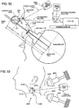
- the present disclosure pertain to a system for performing an image-guided low-energy X-ray therapy procedure on a patient's eye, to systems for planning and controlling such treatments, and to eye alignment-stabilization systems useful in opthalmologic procedures.
- Macular degeneration is a condition where the light-sensing cells of the macula, a near-center portion of the retina of the human eye, malfunction and slowly cease to work. Macular degeneration is the leading cause of central vision loss in people over the age of fifty years. Clinical and histologic evidence indicates that macular degeneration is in part caused by or results in an inflammatory process that ultimately causes destruction of the retina. The inflammatory process can result in direct destruction of the retina or destruction via formation of neovascular membranes which leak fluid and blood into the retina, quickly leading to scarring.
- Treatments for macular degeneration include the use of medication injected directly into the eye (Anti-VEGF therapy) and laser therapy in combination with a targeting drug (photodynamic therapy); other treatments include brachytherapy (i.e., the local application of a material which generates beta-radiation).
- Accurate alignment of a subject's eye is important in a number of situations. For example, when taking certain types of eye measurements, it is critical to know that the eye is in a particular reference position. When measuring the cornea of a patient's eye before therapeutic treatment, it can be important to repeat those measurements after the treatment to determine how much, if any, the treatment has affected the measurements. In order to accomplish this, one must ensure that the eye alignment is in the same position each time the particular measurements are made. Otherwise, the difference in data from before and after the treatment might be due to a change in eye alignment rather than the treatment.
- a number of treatment and surgery procedures typically involving irradiating one or more selected targets in the eye, require a patient's eye to be stabilized or positioned prior to and/or during treatment.
- refractive laser surgery involves ablating corneal tissue of the eye with an ultra-fast, ultra-short pulse duration laser beam, to correct refractive errors in a patient's eye.
- the patient's eye must be stabilized, and either the laser system must be properly and precisely aligned with the patient's eye, or the patient's eye must be properly and precisely aligned with the laser system.
- the eye is predisposed to saccades, which are fast, involuntary movements of small magnitude.
- a patient may voluntarily shift their gaze during surgery, and furthermore, eye position stability is affected by the patient's heartbeat and other physiological factors.
- US2008/049896 discloses an apparatus and method for determining a target-to-surface distance (TSD) between a target region in a body and an actual point of entry of a radiation beam into the body from a radiation source.
- TSD target-to-surface distance
- WO2007/045075 discloses a radiation therapy treatment method comprising imaging a subject and simulating four-dimensional aspects of radiotherapy.
- US2007/195929 discloses a system and method of evaluating dose delivered by a radiation therapy system using a marker that indicates motion.
- WO2008/124801 discloses a radiosurgery system that is configured to deliver a therapeutic dose of radiation to a target structure in a patient.
- US6134294 discloses a device for precision X-irradiation of the macular region of the retina of a patient's eye having a mounting plate mounted to a linear accelerator collimator.
- a Method of Treating a lesion on or adjacent the retina of an eye of a patient with an external-beam radiation device comprises (a) placing the patient's eye in alignment with a known system axis in an external three- dimensional coordinate system, and measuring the eye's axial length; (b) from the known position of the system axis and from the measured axial length, determining the coordinates of the lesion to be treated in the external coordinate system; (c) directing a collimated radiation beam along a known beam axis in the external coordinate system at the lesion to be treated; (d) during said directing, tracking the position of the patient's eye with respect to the known system axis, thus to track the position of the lesion to be treated in the external coordinate system; and (e) based on the known beam axis of the collimated beam in the external coordinate system, and the instantaneous position of the lesion to be treated in the external coordinate system, as determined at least in part by the tracked position of the eye, calculating a
- step (b) includes determining the coordinates of at least one radiation-sensitive structure in the external coordinate system;
- step (d) includes tracking the position of the at least one radiation-sensitive structure in the external coordinate system;
- step (e) includes, based on the instantaneous position of the at least one radiation-sensitive structure in the external coordinate system, calculating a total radiation equivalent received at the at least one radiation-sensitive structure during the treatment; the method further comprising the step of (f) based on the calculated radiation equivalent from step (e), controlling the radiation beam to insure that the at least one radiation-sensitive structure does not receive more than a preselected radiation equivalent during the treatment.
- the method may further provide that step (a) include measuring the axial length of the patient's eye by ultrasound imaging, and step (b) include scaling the measured axial length from step (a) to a standard human-eye model, and determining the coordinates of the lesion to be treated and the at least one radiation-sensitive structure from the eye model.
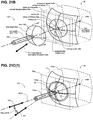
- Step (a) may include determining a patient-eye geometric axis that extends through the center of the limbus and contains a corneal reflection of the patient's eye, and aligning the geometric axis with the known system axis; and step (d) may include tracking the angular deviation of the geometric axis of the eye with the known system axis.
- the method may include attaching on eye guide to the patient's eye, centered thereon so that the geometric axis of the eye corresponds approximately to the axis of the eye guide, and aligning the axis of the eye guide with the known system axis.
- the method may further provide that step (b) include using the measured optical length of the patient's eye to place the patient's in registry with the eye model, and using the coordinates of the lesion to be treated and the at least one radiation-sensitive structure in the model to determine the coordinates thereof in the external coordinate system.
- step (d) may include tracking the position of the eye guide axis with respect to the system axis, thus to track the positions of the lesion and radiation-sensitive structures in the external coordinate system.
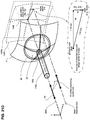
- the eye model may include a virtual medium by which the attenuation of a radiation beam along a known path through the model can be determined; and step (e) may include determining the spatial accumulation of radiation received at the macular region of the eye based the known intensity of the collimated beam, the instantaneous positions of the of the patient's eye, and the attenuation of the beam through the virtual medium along known pathways within the eye.
- the method may further provide that step (e) includes mapping a spatial quantity indicative of a distribution of total radiation onto the eye model, based on the tracked position of the patient's eye during a period of directing a radiation beam at the retinal region of the patient's eye.
- the lesion to be treated may be the macula
- the at least one radiation-sensitive structure may include at least a portion of the optic nerve or optic disk of the eye
- step (e) may include calculating the total radiation equivalent received at the macula and at the optic disk during the treatment.
- Step (f) of controlling the radiation beam may include controlling the radiation beam to do one or more of: (i) achieve a desired dose of radiation at the lesion; (ii) avoid exceeding a selected level of radiation dose at the radiation-sensitive structure; and (iii) avoid exceeding a selected threshold based on the spatial quantity, the threshold indicative of eye-motion-based departure of the beam axis from the selected target.
- the method may further provide that step (e) of calculating total radiation equivalent received at the lesion to be treated and the at least one radiation-sensitive structure during the treatment, may include determining a time-increment vector summation of a parameter indicative of an eye-motion-based departure of the beam axis from the selected target lesion to be treated.
- Step (e) of calculating total radiation equivalent received at the lesion to be treated and the at least one radiation-sensitive structure during the treatment may include modulating a pre-determined radiation distribution model representing predicted radiation dose distribution to be received by tissue of the patient from the collimated radiation beam in the absence of eye motion, the modulation based tracked eye motion during treatment, so as to determine a radiation dose distribution accounting for actual eye motion during treatment.
- the method may further provide that step (e) of calculating total radiation equivalent received at the lesion to be treated and the at least one radiation-sensitive structure during the treatment, may further include sequentially performing the modulating a pre-determined radiation distribution model for a plurality of successive time increments during radiation treatment so as to determine a cumulative dose distribution during the course of treatment; and step (f) may include (i) comparing the cumulative dose received by a selected non-target anatomical structure with a pre-determined dose threshold quantity to determine if the threshold has been exceeded and (ii) in the event that the threshold has been exceeded, controlling the controlling the radiation beam or beam axis to reduce or eliminate further radiation dose to the selected non-target anatomical structure.
- the method may further provide that step (e) of calculating total radiation equivalent received at the lesion to be treated and the at least one radiation-sensitive structure during the treatment; further includes sequentially performing the modulating a pre-determined radiation distribution model for a plurality of successive time increments during radiation treatment so as to determine a cumulative dose distribution during the course of treatment; and wherein step (f) includes (i) comparing the cumulative dose received by a selected anatomical target region with a pre-determined dose threshold quantity to determine if the threshold has been reached, and (ii) in the event that the threshold has been reached, controlling the radiation beam or beam axis to reduce or eliminate further radiation dose to the selected anatomical target region.
- the method may further provide that the lesion may be a macular lesion, wherein the radiation beam is an collimated X-ray beam, and step (c) may include determining the position of the patient's macula in the treatment coordinate system from the known position of the eye and the coordinates of the macula in the external coordinate system, and determining a treatment axis in the external coordinate that intersects the patient macula.
- Step (c) may include directing a collimated X-ray beam along each of at least two different known treatment axes in the treatment coordinate system at a region of the macular region of the patient's retina.
- Step (f) may include controlling the X-ray beam to deliver approximately equal doses of radiation at the patient's macula along each of the different known treatment axes.
- step (f) includes turning off the beam being directed onto the patient's eye when the position of the patient's macula, as tracked in step (c), relative to the axis of the beam, is greater than a predetermined threshold distance.
- Step (f) may include directing the beam against the patient's macular region until the spatial accumulation of radiation mapped at the macula of the eye model reaches a predetermined dose level.
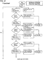
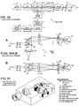
- a Radiotherapy System for treating a target area in a patient with an irradiation beam comprises: (a) a tracking assembly for tracking the position of a patient body region containing the target area and at least one radiation-sensitive area with respect to a known reference axis in an external coordinate system; (b) a beam source for directing an irradiation beam at the patient target area along a known treatment axis in the external coordinate system; and (c) a processor operatively connected to the tracking device and beam source; the processor operable to: (i) determine, from the known position of body region in the external coordinate system, the coordinates of the target area to be treated and the coordinates of the at least one radiation-sensitive patient structure; (ii) during a period when the irradiation beam is being directed along the treatment axis at the target area, and based on information received from the tracking device, track the positions of the target area to be treated and the at least one radiation-sensitive structure; (iii) based on the known beam axis
- the system may comprise a tracking assembly which includes (i) an imaging device for recording an image of a region of the patient's body that contains natural or fiducial landmarks that define a geometric axis of the imaged region and (ii) an image detector operably connected to the imaging device for converting the recorded image to a digital image made up of known-coordinate pixels, and the processor may be operably connected to the detector for determining pixel coordinates of the geometric axis of the body region and step (ii) of the processor operation includes using the pixel coordinates of the geometric axis, relative to known pixel coordinates of the reference axis, to track the position of the patient body region relative to the reference axis.
- the system may be configured for treating an ocular lesion, wherein the body region includes the patient eye, the target area includes the ocular lesion, the at least one radiation-sensitive structure includes the optic disc of the eye, the natural landmarks of the eye that define its geometric axis are the center of the limbus and a first corneal reflection, and the beam source produces a collimated x-ray beam.
- the system may alternatively include an eye guide adapted to be placed on the patient's eye, centered thereon so that the geometric axis of the eye corresponds approximately to the axis of the eye guide, and a detector for determining the coordinates of the axis of the eye guide in the external coordinate system, and the processor may be operably connected to the detector for determining the coordinates of the eye guide axis and step (ii) of the processor operation includes using the coordinates of the eye-guide axis, relative to the known coordinates of the reference axis, to track the position of the patient's eye relative to the reference axis.
- the system may be configured so that the tracking system is operable to capture a plurality of time-sequenced images of the body region and its landmarks during the treatment method, and the processor is operable to determine the coordinates of the body region geometric axis for each of the plurality of images, and in step (ii) to determine a time-dependent change in the coordinates of the target area to be treated and the at least one radiation-sensitive structure.
- the system may be configured so that the processor is operable to carry out, in step (iii) generating a map of total equivalent radiation covering the target area and the at least one radiation-sensitive area in the patient body region, and in step (iii), to determine from the total equivalent radiation map, the radiation equivalent received at any time during treatment by the target area and at least one radiation-sensitive area.
- the system may be configured so that the body region includes the patient eye, the target area includes the ocular lesion, the at least one radiation-sensitive structure includes the optic disc of the eye, and the processor is operable, to carry out in step (iii) generating a map of total equivalent radiation covering the target area and the at least one radiation-sensitive area in the patient body region, and in step (iii), determining from the total equivalent radiation map, the radiation equivalent received at any time during treatment by ocular lesion and at least one radiation-sensitive area.
- the system may be configured so that the target area includes the ocular lesion, the at least one radiation-sensitive structure includes the optic disc of the eye, and the processor includes a model of the human eye by which the coordinates of the lesion to be treated and the at least one radiation-sensitive structure can be determined, when the patient's eye is superimposed on the eye model.
- the eye model in the processor may include a virtual medium by which the attenuation of a radiation beam along a known path through the model can be determined, and the processor is operable to determine from the known intensity of the beam and the length of the radiation path through the virtual medium within the eye model, the amount of radiation that is received by the retina in the eye model.
- the system may be configured so that the body region includes the patient eye, the target area includes the ocular lesion, the at least one radiation-sensitive structure includes the optic disc of the eye, wherein the processor is operable, by determining the position of the ocular lesion in the external coordinate system, to determine a treatment axis in the treatment coordinate system that intersects the lesion.
- the processor may be operable to determine at least two different treatment axes in the treatment coordinate system, and to control the radiation beam to deliver approximately equal doses of radiation at the lesion along each of the different known axes.
- the processor is operable to turn off the beam being directed onto the patient's eye when the distance between the position of the patient's lesion, as determined in operation (d)(ii), and the intersection of the axis of the beam on the retina, is greater than a predetermined threshold distance.
- the processor may be operable to direct the beam against the patient's retinal region until the spatial accumulation of radiation mapped at the lesion of the eye model reaches a predetermined dose level.
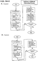
- One embodiment includes Machine-Readable Code operable on an electronic computer included in a Radiotherapy System which is operable for monitoring the total radiation dose received at a target site during the course of treatment in which the target site is irradiated with a collimated x-radiation.
- the code may be operable to perform the steps comprising: (a) defining, in an external coordinate system, coordinates for (i) a reference axis, (ii) a radiation-beam axis, and (iii) the target site which, when a body axis having a known relationship to the target site is aligned with the reference axis, places the radiation beam at the center of the target area, (b) receiving from a body tracking device, ongoing information during the course of radiation treatment on the position of the body axis with respect to the reference axis, (c) from the information received in step (b), and from the known intensity of the beam at the radiation beam, calculating the spatial distribution of radiation received in the region of the target site over the course of the treatment, and (d) using the spatial distribution of radiation calculated in step (c) to monitor the total radiation dose at the target site over the course of the treatment.
- the machine-readable code may be configured to carry out steps wherein the target area includes the ocular lesion, the body axis is the geometric axis of the eye, and information received from a body tracking device is in the form of ocular images from which the geometric axis of the eye can be determined.
- the eye may be irradiated during the course of treatment by an a collimated x-radiation beam directed at the target site along at least two different beam axes.
- the machine-readable code may be configured to carry out steps wherein an eye guide is centered on the eye such that an eye guide axis corresponds approximately to the geometric axis of the eye, and the information received from a body tracking device is in the form of information on the position of the eye guide.
- the machine-readable code may be further operable, in step (a) to determine the coordinates, in the external coordinate system, of the optic disc of the patient's eye, based on a known spatial relationship between the lesion of the optic disc, and further operable in step (d) to use the spatial distribution of radiation calculated in step (c) to monitor the total radiation dose at the optic disc during the course of treatment.
- One embodiment includes Machine-Readable Code operable on an electronic computer included in a Radiotherapy System which is operable for controlling the treatment of an ocular lesion by exposing the lesion to a collimated x-radiation beam.
- the code may be operable to perform the steps comprising: (a) using information received from a eye-tracking system to determine a geometric axis of the eye in an external coordinate system, (b) with the geometric axis of the eye placed in alignment with a reference axis, determining the coordinates of the lesion in an external coordinate system, (c) from the coordinates of the ocular lesion determined in step (b), determining a beam axis that intersects the lesion with the patient eye in an defined position with respect to the reference axis, and (d) controlling the position of an x-ray beam source to position the beam along the beam axis determined in step (d).
- the machine-readable code may be configured to carry out steps wherein the information received from the eye tracking system is an ocular image from which the geometric axis can be determined by determining the center of the sclera and a corneal reflection from the ocular image.
- the machine-readable code may be configured to carry out steps wherein an eye guide is centered on the eye such that an eye guide axis corresponds approximately to the geometric axis of the eye, and the information received from a body tracking device is in the form of information on the position of the eye guide.
- step (c) may further include determining two or more beam axes that intersect the lesion with the patient eye in an defined position with respect to the reference axis.
- the computer may be operably connected to a beam-source robotic device for position the beam along a selected beam axis, and step (d) may include acting on the robotic device to shift the beam axis during the course of treatment, from one beam axis to another determined in step (c).
- One embodiment includes Machine-Readable Code operable on an electronic computer in a treatment system for treating a lesion of a patient's eye by directing a collimated radiation beam along a beam path to the lesion and including, operably connected to an eye-tracking device which includes an eye-contact member configured to engage the eye and having visible fiducials, and a camera configured to capture an electronic image of the eye.
- the code may be operable to execute instructions effective to perform the steps comprising: (a) aligning the camera to a known position and/or orientation with respect to a treatment system coordinate system (system coordinates) wherein the camera is directed to the eye as engaged with the contact member; (b) capturing an image of the eye as engaged with the contact member;(c) identifying one or more pixels of the image representing the location of an axis of the contact member; (d) determining from image data that the eye-guide axis is aligned to a known position and/or orientation with respect to the system coordinates; (e) determining from image data the location of the center of limbus in the system coordinates; and (f) determining a deviation of the location of the center of limbus to a known position and/or orientation of the eye-guide.
- the machine-readable code may be configured so that the step (e) of determining the location of the center of limbus includes: (i) determine a portion of the image including all or a portion of the exposed portion of the limbus boundary, and identifying the locations in the image corresponding to the limbus boundary image; (ii) determining a mathematical representation of a "best fit" shape corresponding to the limbus boundary locations; and (iii) calculate a center of "best fit" shape so as to determine the location of the limbus center.
- the code may further include the steps of: (g) registering the positions and/or orientations determined in steps (a-d) of one or both of contact member and limbus in a virtual computer eye model; (h) calculating the position of an anatomical eye structure in the system coordinates based on the registered eye model; and (i) controlling the at least one operational aspect of the collimated radiation beam in response to the calculated the position of the anatomical eye structure.
- One embodiment includes a Computer-Executed Method for use in a radiation treatment device including a computer processor and a body-part motion tracking device operably connected to the computer processor, the tracking device including an body-contact member configured to engage the surface of a body part of the patient which includes a radiation treatment target, and a camera configured to capture an electronic image of the body part
- the processor may be effective to execute instructions to perform the steps comprising: (a) determining an initial position and orientation of the body part, based on: (i) determining the alignment of the contact member as engaged with the body so as to have a known orientation relative to an anatomical axis of the body part and a known position relative to the contacted body surface; and (ii) determining the alignment of the contact member as engaged with the body with the radiation treatment device so as to have a known initial position and orientation in a coordinate system of radiation treatment device; (b) determining an initial position of the treatment target in the coordinate system of radiation treatment device, based on determining the relative position of the treatment target to the contact member;
- the computer-executed method provides the body part includes a treatment target is selected from the group consisting essentially of a portion of the brain, spine, a breast, musculoskeletal tissue, vasculature, abdominal and gastrointestinal lesions.
- the computer-executed method provides that the body part is an eye, wherein the treatment target includes a portion of the retina, and wherein the contact member includes a lens element contacting the surface of the eye.
- a method of treating a patient with radiation emitted from a radiation source comprises in any operative order the steps of: a) providing a phantom model including a representation of patient anatomy; b) registering the phantom model with virtually projected radiation beams from a virtual radiation source and simulating dose deposition in the phantom model; c) simulating movement of the phantom model while keeping the registration between the phantom model and the virtually projected radiation beams; d) registering the phantom model with a subject receiving radiation, and registering the virtually projected radiation beams with a radiation source treating the subject; e) registering movement of the patient with movement of the phantom model in the simulation; f) determining, from the model as registered with the patient, at least a dose of radiation absorbed by the treated tissue during the treatment time.
- the phantom model may include an anatomic representation of one or more structures of an eye, such as a treatment target regions (areas or volumes planned to receive radiation dosage), e.g., a portion of a retina.
- the model may also include representation of non-target anatomical structures (areas or volumes planned to have radiation dosage minimized or avoided), e.g., an optic disk, an optic nerve and a lens of the eye; and adjacent anatomical structures, e.g., volumes through which the radiation beam propagates and is attenuated, both before reaching a target region, and beyond a target region.
- a phantom model may be modified based on one or more measured patient anatomic features, such as by scaling a phantom eye model relative to a measured eye dimension, e.g., an A-scan eye axial length.
- medical imagery may be registered, superimposed and/or scaled to the model and included to provide patient-specific content.
- a fundus image of a patient's retina (optionally scaled) may be superimposed on a retinal representation in the model so as to permit imaged features to be superimposed on model features, such as treatment plan target region data in relation to a visible lesion, the optic disk, and the like.
- a phantom model may be registered or correlated with measured movement of a patient so as to determine a corresponding virtual movement of the model.
- a real radiation source may be registered or correlated with the model so as to correlate the radiation emission configuration of the radiation source with the virtual movement of the model.
- a real radiation dose to anatomy may be determined by reference to the model, where the model includes representations of anatomy and radiation source, by determining a virtual movement of the model correlated with real or detected patient movement.
- Embodiments having aspects of the invention may further including modifying the radiation treatment in response to the determined radiation dose, such as by automatically or manually reducing or stopping radiation emission; or by automatically or manually reorienting the radiation source.
- an algorithm for determining motion of a point on a retina comprises: from an image of a fiducial on an eye, correlating position of the fiducial to a structure on the retina.
- the correlation may be performed via a mathematical transformation., such as a trigonometric transformation.
- the mathematical transformation may be performed in a software program.
- the algorithm may further comprise detecting a subsequent image after a period of time and correlating the new position of the fiducial relative to the first position, and a corresponding error function may be created or generated.
- the algorithm may further comprise detecting more than one fiducial and correlating with greater than one coordinate of the retina.
- the fiducial position may be placed or registered in an external coordinate frame, such as the system reference frame of a radiotherapy treatment device.
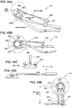
- Eye-stabilization system comprises of an eye-contact device (eye-guide) for securing a patient eye at a selected position, such as may be used cooperatively with an ocular stabilization and alignment device, as described in the co-invented priority applications, particularly No. 12/103,534 filed April 15, 2008 and No. 12/027,083 filed February 1, 2008 .
- eye-contact device eye-guide
- ocular stabilization and alignment device as described in the co-invented priority applications, particularly No. 12/103,534 filed April 15, 2008 and No. 12/027,083 filed February 1, 2008 .
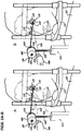
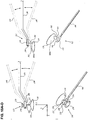
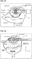
- the eye-contact device or eye-guide comprises, in operative condition, (a) a lens body having an internal concave contact surface adapted to be placed against the front surface of a patient's eye so as to cover at least a portion of the cornea, an external surface including one or more mounting locations, and a transparent widow portion arranged to permit, when in operative position, visualization of an interior portion of the eye via the cornea; (b) a support member mountable to a base; and (c) two or more linkages pivotally mounted to the support member and connecting to a mounting location of the lens body, the links configured form a assembly supporting the lens body against the eye.
- the eye-guide further comprising an adjustment mechanism engaging at least one linkage and configured to provide adjustment of the range and/or resistance of at least one pivotal degree of freedom of the lens body with respect to the support member.
- the window portion may have at least one optical property selected from the group consisting of a selected transparency, a selected refraction, a selected magnification, a selected filtration, a selected polarity, and a selected pattern of markings.
- the eye-guide may further comprise a port in fluid communication with the contact surface by which a negative pressure can be applied between a patient's eye and the contact surface, to stabilize the position of the eye with respect to the contact device.
- the eye-guide may further comprise a biasing mechanism operatively connected to the contact device connector for biasing the eye-contact device against the eye with a force sufficient to the hold the contact device against the eye.
- a patient's eye may be aligned and stabilized for diagnostic or therapeutic purposes, such as radiotherapy treatment.
- the method may comprise: (a) engaging the anterior surface of the eye with a contact lens member, the contact lens member having a defined axis; (b) aligning the lens with the eye so that the lens axis intersects the center of the limbus of the eye and so that the lens axis has a known orientation to the corneal surface at the center of the cornea so as to define an axial anatomic axis of the eye; and (c) aligning the lens axis with a coordinate axis of the medical device, so that the coordinate axis of the medical device has a known orientation to the axial anatomic axis of the eye.
- the step (b) of aligning the lens with the eye may include: (i) electronically capturing one or more images including the eye and the lens member; (ii) processing the image in a computer processor so as to determine the location of the lens member axis relative to the location of the limbus; and (iii) adjusting the position of the lens member relative to the eye until the lens axis substantially intersects the center of the limbus of the eye.
- the sub-step (ii) of processing the image to determine the location of the lens member may include: A. processing the image so as to determine the location of the center of the contact lens in a coordinate system; B. processing the image so as to determine the location of the center limbus in the coordinate system; and C. comparing the location of the center of the contact lens of the center limbus in the coordinate system so as to determine the difference in location, if any.
- the sub-step (a) of determining the location of the center of the contact lens may include: (i) electronically detecting a contrasting image of each fiducial to define a respective fiducial data set; (ii) mathematically determining the center of each fiducial data set; (iii) from the known location of the fiducials relative to an eye contact surface computing the location of the center of the eye contact surface in the coordinate system.
- the sub-step (b) of determining the location of the center limbus may include 1. electronically detecting a contrasting boundary between sclera and iris to define a boundary data set; 2. mathematically fitting geometric shape to represent the boundary data set; and 3. computing the center of the geometric shape in the coordinate system.
- step (c) of aligning the lens axis with a coordinate axis of the medical device may include: (i) electronically capturing one or more images including the lens member as engaged and aligned with the eye; (ii) processing the image in a computer processor so as to determine the one or both of an orientation and a position of the lens member in the coordinate system of the medical device; (iii) adjusting one or both of the orientation and the position of the lens member relative to the coordinate axis of the medical device until the coordinate axis of the medical device has a known orientation to the axial anatomic axis of the eye.
- the method may further include: (d) determining a distance coordinate axis of the medical device to the contact lens member as engaged and aligned with the eye; in the wherein the determination of the distance includes (i) electronically capturing one or more images including the contact lens member as engaged and aligned with the eye; and (ii) processing the image in a computer processor so as to determine the distance.
- motion of a patient's eye may be measured or tracked for a diagnostic or therapeutic purpose, such as radiotherapy treatment.
- the method may comprise: (a) determining an initial position and orientation of the eye, including: (i) engaging the anterior surface of the eye with a contact lens member; (ii) aligning the contact lens member with the eye so as to have a known orientation relative to an anatomical axis of the eye and a known position relative to the contacted eye surface; and (iii) aligning the contact lens member with the medical device so as to have a known initial position and orientation in the coordinate system of medical device;
- the method may further comprise: (b) electronically capturing a plurality of time-sequenced images including the contact lens member while maintaining the engagement and alignment of the contact lens member with the eye; (c) processing the images in a computer processor so as to determine one or both of an orientation and a position of the contact lens member in the coordinate system of the medical device at the time of capture of each image; and (d) determining for each image, from the orientation and/or position of the contact lens member at the time of capture of the image, the change from the initial orientation and/or position of the contact lens in the coordinate system of medical device, so as to track the sequential motion of the eye in the coordinate system of medical device.
- motion of a patient's eye may be used to infer motion of a target tissue or other region within the eye, for a diagnostic or therapeutic purpose, such as radiotherapy treatment.
- the method may further comprise: (e) determining the position of the target tissue relative to the anatomical axis and contacted eye surface; and (f) following step (a) of determining an initial position and orientation of the eye, determining an initial position of the target tissue in the coordinate system of medical device; (g) determining for each image, from the change from the initial orientation and/or position of the contact lens, the change from the initial position of the target tissue in the coordinate system of medical device, so as to track the sequential motion of the target tissue in the coordinate system of medical device.
- the method may further comprise: the step of changing at least one operational parameter of the medical device in response to a change from the initial position of the target tissue.
- the medical device is an external radiation beam treatment device configured to treat the patient by emitting a collimated radiation beam directed to the target tissue;
- the change in operational parameter may include one of (i) re-directing the collimated radiation beam to follow target tissue motion and (ii) interrupting the emission of the beam upon a threshold of motion of the target tissue.
- Exemplary methods and devices having aspects of the invention may embody a radiotherapy treatment plan providing for propagation of an external radiation beam to target tissue, where passage through tissue effects beam characteristics.
- a radiotherapy treatment plan providing for propagation of an external radiation beam to target tissue, where passage through tissue effects beam characteristics.
- motion of a region including target tissue within the eye may be used to track the deposition of radiation dose to anatomical structures.
- the method may further comprise: (h) providing a virtual radiation dose distribution model representing a treatment radiation dose distribution to a region of tissue including the target tissue; and (i) determining, from the dose distribution model and from the determined motion of the target tissue, a modified dose distribution model accounting for eye motion.
- a dose distribution accounting for eye motion may be used to trigger radiotherapy operation changes.
- the method may further comprise: (j) defining a geometric parameter in a coordinate system of the region of tissue including the target tissue, the geometric parameter characterizing a reference location of an time-increment of radiation dose of the model provided in step (h); (k) defining an accumulation vector providing a vector summation of the geometric parameter in a coordinate system of the region of tissue including the target tissue; (l) performing steps (h) and (i) for a time-sequenced image captured per step (c) to determine a modified time-increment dose distribution and a respective value of the geometric parameter for the time increment; (m) adding the time-increment geometric parameter to the accumulation vector; (n) comparing the value of the accumulation vector in one or both of magnitude and direction to one or more predetermined threshold values to determine if the value exceeds the threshold; (o) in the event that the value in step (n) exceeds a threshold, interrupting the emission of the radiation beam.
- the geometric parameter may have linear relationship or a nonlinear (e.g., quadratic) relationship to a change from the initial position of the target tissue.
- the target tissue includes a portion of the retina of a patient's eye
- the geometric parameter the difference in the location for each time sequence of a centroid of the dose distribution in a plane of the retinal surface relative to an initial location of the centroid of the dose distribution.
- an algorithm for aligning a patient body part with a radiation device comprises: (a) defining a normal axis to the body part (e.g., by locating fiducials on the body part); (b) aligning the normal axis to a pixel on a camera image visualizing the body part; and (c) linking the pixel on the camera image to a coordinate frame of a robotic positioning system thereby linking the normal axis of the body part to an axis of the robotic positioning system.
- the algorithm may further comprise determining the distance between the body part and the robotic positioning system wherein the distance is measure along the normal axis.
- normal axis may be defined by detecting fiducials on a device that contacts the eye, such as adjacent the limbus of the eye.
- a treatment target on the retina, such as the macula, may be located with respect to the normal axis by an eye axial length measurement.
- the device may be provided to include an eye-guide device configured to engage the eye and a camera configured to capture an electronic image of the eye, the eye-guide having visible fiducials and the camera linked to a computer processor.
- the method may include: (a) aligning the camera to a known position and/or orientation with respect to the medical device coordinate system wherein the camera is directed to the eye as engaged with eye-guide; (b) capturing an image of the eye as engaged with eye-guide; (c) identifying one or more pixels of the image representing the location of the eye-guide central axis; (d) determining from image data that the eye-guide central axis is aligned to a known position and/or orientation with respect to the medical device coordinate system; (e) determining from image data the location of the center of limbus in the system coordinates; and (f) determining any deviation of the location of the center of limbus to a known position and/or orientation of the eye-guide.
- the method may further include (i) that the camera is aligned co-axially with a principle axis of the medical device coordinate system ("Z axis"); (ii) that the processor is programmed with software code acting on camera image data in computer memory, so as to carry out calculations and algorithms based on image data, and so as to determine pixel-scale distances between locations within an image ("distance within the image”); and (iii) that the eye-guide includes at least three fiducials in known position with respect to an eye-guide central axis.
- step (c) of identifying a pixel includes: (i) determining a the portion of the image including a first fiducial ("fiducial 1"); (ii) determining a geometric center of the fiducial image area; (iii) select a pixel representing the fiducial center; and (iv) determining a pixel of the image representing the eye-guide central axis based on the known position of the first fiducial.
- the method may further provide that:
- the method may further provide that the step (e) of determining the location of the center of limbus includes: (i) determine a portion of the image including all or a portion of the exposed portion of the limbus boundary, and identifying the pixel locations corresponding to the limbus boundary image; (ii) determining a mathematical representation of a "best fit" shape corresponding to the limbus boundary pixel data; and (iii) calculate the center of "best fit" shape so as to determine the location of the limbus center.
- the method may further include the steps: (g) registering the positions and/or orientations determined in steps (a-d) of one or both of eye-guide and limbus in a virtual computer eye model. (h) calculating the position of an anatomical eye structure in the device coordinate system based on the registered eye model.
- Eye contact device and lid retractor In an exemplary embodiment of eye contact device having aspects of the invention for use in a system for securing a patient eye at a selected position, the device comprises: (a) a lens body having an internal concave contact surface adapted to be placed against the front surface of a patient's eye so as to cover at least a portion of the cornea, an external surface including one or more mounting locations, and a transparent widow portion arranged to permit, when in operative position, visualization of an interior portion of the eye via the cornea; (b) a support member mountable to a base; and (c) two or more linkages pivotally mounted to the support member and connecting to a mounting location of the lens body, the links configured form a assembly supporting the lens body against the eye.
- the device may further include an adjustment mechanism engaging at least one linkage and configured to provide adjustment of the range and/or resistance of at least one pivotal degree of freedom of the lens body with respect to the support member.
- the window portion may have at least one optical property selected from the group consisting of a selected transparency, a selected optical refraction, a selected magnification, a selected optical filtration, a selected optical polarity, and a selected pattern of markings.
- the device comprises: (a) a lid-engaging spoon-like hook mounted configured to hold an eyelid without injury; (b) an elastic tension member (e.g., an elastic strap or tube) linked to the spoon-like hook and linked to a securing base member (e.g. a clip or other attachment), the tension member being adjustable in both tension and direction of application of tension relative to the eye.
- the tension adjustment may include altering the length of the tension member (e.g., a conventional strap adjustment, Velcro adjustment, or the like) or may include altering the location of the securing base member (such as attaching a clip to a different location).
- the tension member may include a tension release mechanism (such as a magnetic release).
- the securing base member may be configured to attach to clothing of a subject or to the subjects body.
- the collimator comprises: (a) a collimator body configured to be supported in operative association with an X-ray source assembly having an X-ray source; (b) a collimator axis defining the X-ray beam direction of propagation; (c) a collimator exit aperture supported relative to the collimator body so as to determine one or more cross-sectional characteristics of the X-ray beam; (d) either or both of the collimator body and the collimator exit aperture include one or more beam-effecting elements configured to produce a collimated X-ray beam directable to intersect a treatment target of a subject's body, such that least one of the beam-effecting elements is moveable to adjust a physical parameter of the X-ray beam.
- the beam effecting element may include one or more of the following: (i) a extendable body portion configured to alter the distance of the aperture from the X-ray source; (ii) a movable portion configured to alter the position of the aperture relative to the X-ray source, so as to alter the direction of the beam axis; (iii) a movable portion configured to alter the rotational position of the aperture with respect to the collimator axis; and (iv) a movable aperture element configured to be adjusted to change one of a beam diameter and a beam cross-sectional shape.
- one or more movable elements are mounted to one or more actuators configured to move the elements during the course of X-ray treatment, the actuators controlled by a tracking controller effective to detect a motion of the treatment target during treatment; the controller effective to control the actuators so as to adjust a physical parameter of the X-ray beam so as to substantially maintain intersection of the beam with the treatment target in the event that the target moves during treatment.
- FIGURES and the associated descriptions are provided to illustrate embodiments of the disclosure and not to limit the scope of the disclosure.
- reference numbers are reused to indicate correspondence between referenced elements.
- the FIGURES are in simplified form and are not necessarily to scale.
- directional terms such as top, bottom, left, right, up, down, over, above, below, beneath, rear, and front are used with respect to the accompanying figures. Such directional terms are not to be construed as limiting the scope of the invention in any manner.
- a “lesion” refers to a localized area of diseased or disordered tissue.
- An “ocular lesion” may refer to a retinal or non-retinal lesion, and a retinal lesion may refer to any localized pathology associated with the retina, including macular degeneration, such as wet and age-related macular degeneration where the lesion is associated with the macula, lesions associated with tumors or with vascular abnormalities, drusen, including optic-disc drusen, diseases of the optic disc, lesions associated with inflammation, such as Behcet's Syndrome, lesions associated with heritable diseases, such as Watanabe Heritable HyperLipidemia, and lesions associated with viral, bacterial, or parasitic infection, such as lesions associated infection, such as lesions associated with Trypanosoma infection.
- a "radiation-sensitive structure” refers to a normally healthy tissue area or structure that is in the vicinity of a lesion, and which is at risk of loss of function by overexposure to radiation, e.g., by a collimated x-ray beam.
- An example is the optic disc, which is in the vicinity of the macula in the retina of a patient eye.
- an “external coordinate system” or “treatment coordinate system” refers to the coordinate system in which the coordinate positions of various components of a treatment system, such as an eye guide, a tracking system, and a radiation beam axis can be determined and their positions with respect to one another known.
- a “patient axis” refers to an internal axis defined by natural or fiducial landmarks on the patient, and which can therefore be used in tracking patient position by a suitable tracking system in the external coordinate system.
- One exemplary patient axis is an ocular "geometric axis" defined as a line extending through the center of the limbus and through the center of a corneal reflection, e.g., the first reflection produced from the cornea when illuminated by a light source.
- an "eye guide axis" refers to an axis defined by an eye guide in the external coordinate system. Ideally, an eye guide is centered on the patient eye so that the geometric axis of the eye in the patient coordinate system is aligned with the eye guide axis in the external coordinate system. This can be done, for example, by centering the eye guide on the eye, e.g., with respect to the limbus of the eye.
- a “reference axis” or “system axis” refers to an axis having known, and defined coordinates in the external coordinate system.
- the reference axis may be defined by a given patient axis at a known body position, so that the body position can be tracked by movement of the body axis with respect to the reference axis.
- the patient region to be treated is a retinal structure, such as the macula
- the patient eye is initially placed in a preferably immobilized position with the patient looking straight ahead.
- the geometric axis of the eye is determined in this position, and the coordinates of the geometric axis in the external coordinate system then defines the reference axis.
- the reference axis can be thought of as the axis which forms the frame of reference for transforming internal body coordinates to the external coordinate system, by matrix transformation, where this transformation is determined according to a measured variation of the body axis with respect to the reference axis.
- the reference axis may be defined by the eye guide axis when the patient is initially placed in a preferably immobilized position with the patient looking straight ahead. The eye guide axis then becomes the frame of reference for determining the position of the eye with respect to the reference axis.
- the "axial length" of the eye is the distance along the geometric axis of the eye between the front of the cornea and the back of the retina. This distance can be measured by the ultrasound according to known methods.
- a “standard model of the eye” or “human-eye model” refers to a geometric model of the eye as constructed from a large population of human eyes. This model will have its own coordinate system in which the coordinates of ocular structures of interest, including the macula and optic disc, are known.
- a patient eye is "scaled to human-eye model" by aligning a known axis of the patient eye, e.g., the geometric axis, with the same axis in the model, and scaling the model so that axial length of the model matches the measured axial length of the patient, in effect, superimposing the model on the patient eye.
- the coordinates of internal ocular structures from the model can be assigned to the patient eye, to define internal ocular coordinates of the patient-eye structures.
- These internal coordinates in turn, can be transformed to the external coordinates from the known transformation between the geometric axis of the patient eye with the reference axis.
- the eye model may contain a "virtual medium" which simulates the radiation-attenuation characteristics of the medium, e.g., vitreous human, within the actual eye.
- a "time increment vector summation of a parameter indicative of an eye-motion-based departure of a beam axis from the selected target to be treated” is determined by the steps of (i) at successive points in time, e.g., intervals of tenths or hundredths of a second during the course of radiation treatment, using the tracked position of the eye to determine the instantaneous coordinates of the target in the external coordinate system, (ii) from the known position of the radiation beam axis in the external coordinate system, determining the position of the radiation beam with respect to the target position, (iii) using the positions determined in (ii) to calculate a vector representing the magnitude and direction of the beam position with respect to the target position, and (iv) summing these vectors over time.
- a "collimated radiation beam” refers to an x-radiation beam that has been collimated, e.g., by passage through a narrow-bore filter.
- Randomtion equivalent refers to a radiation dose received at a position on or near a lesion, and determined by integrating the instantaneous radiation dose that position over total exposure time.
- “Radiation equivalent” may refer to a integral parameter based on radiation beam geometry and time history, in which the integral parameter may be correlated with an equivalent radiation dose based on known radiation beam properties.
- the relation between beam duration and radiation dose at a point intersected by the beam may be a simple linear relationship, allowing a integral time-position parameter (sometimes referred to as "Accumulation Factor” herein) to be used as an equivalent to a cumulative radiation dose at a geometric location (e.g., in monitoring and controlling or "gating" the beam).
- a constant dose rate e.g., Gy/sec
- the relation between beam duration and radiation dose at a point intersected by the beam may be a simple linear relationship, allowing a integral time-position parameter (sometimes referred to as "Accumulation Factor” herein) to be used as an equivalent to a cumulative radiation dose at a geometric location (e.g., in monitoring and controlling or “gating" the beam).
- a integral time-position parameter sometimes referred to as "Accumulation Factor” herein
- a “tracking assembly” refers to various imaging and/or coordinate tracking devices in the external coordinate system that can be used to track the position of a body region, e.g., patient eye.
- the tracking system may include (i) a camera for imaging the body region being tracked, (ii) a light source from illuminated the imaged region, and (iii) a detector on which the camera image can be represented as a digital image.
- the tracking system includes the fiducial(s) applied to the body, and external signal-responsive element(s) for detecting the emitted or reflected signals and determining from the signals, the position(s) of the fiducial(s) in the external coordinate system.
- a tracking system may include both imaging and signal responsive elements.
- the tracking system may include an imaging system to image the eye and attached fudicials, such as eye guide fiducial and a fiducial tracking device.
- Machine-readable code operable on an electronic computer refers to software or hard-wired instructions used to control the logic operations of the computer.
- the term computer or processor refers to an electronic computer or its specific logic-processing hardware.
- the machine-readable code is embodied in a tangible medium, such as a hard disc or hard-wired instructions.
- the invention includes system for treating a target area in a patient with an irradiation beam.
- the system includes a tracking assembly for tracking the position of a patient body region containing the target area and at least one radiation-sensitive area with respect to a known reference axis in an external coordinate system.
- a tracking system for tracking patient eye movement, based only of natural features of the eye, is detailed in Sections VIIC and with respect to FIGS. 54-56 .
- a tracking system for tracking the position of the eye, by tracking an eye guide centered on the eye, is detailed in Sections IV and V .
- a beam source for directing an irradiation beam at the patient target area along a known treatment axis in the external coordinate system, as detailed in Section IIC below.
- a processor in the system (described below with reference to Section IID) is operatively connected to the tracking device and to the beam source is operable to carry out operations operation for:
- FIG. 1A is a perspective view of an exemplary embodiment having aspects of the invention of an X-ray treatment system 10 for treating ocular diseases.
- FIG. 1B is a plan view of the treatment system embodiment of FIG. 1A , further showing associated system processors 501 and operator input/output devices 502-503, depicted as installed in an exemplary operating console 500.
- FIGS. 2-6 illustrate alternative or additional aspects of system 10.
- System 10 includes a radiotherapy generation module or X-ray source assembly 420, for example comprising one or more X-ray tubes 112, each having a collimator for producing a tightly collimated X-ray treatment beam.
- the system 10 includes a radiotherapy control module which preferably includes an interface display 502, processing module 501, operator input devices 503 and a power supply (not shown).
- the system includes an imaging module 400, which can include one or more cameras and associated light sources, such as LEDs or low-powered lasers.
- the processing module, and machine-readable code used to control various operations of the module will be described below in Section IID.
- the module is also referred to herein as a processor and an electronic computer.
- System 10 comprises an eye alignment and/or stabilizing module including an eye contact device or eye-guide device 625 having aspects of the invention, which is describe further with respect to FIGS. 2 and 16 , among other places.
- the eye alignment and/or stabilizing module is configured for use with system 10, although it additionally may be usefully employed independent of system 10.
- the eye stabilization device may further comprise sensors or motion detection aids or cameras to assist with delivery of radiation to a patient.
- system 10 includes an automated positioning system (APS) 115 for moving and aiming the X-ray source assembly 420 (including X-ray tube 112 and collimator 118) to direct a treatment beam to a target from one or more selected directions. Further description of system 10 follows below.
- APS automated positioning system
- FIG. 1B illustrates one particular embodiment of an operating consol 500 having aspects of the invention, suited to house the components of system 10 and to provide for its effective and safe operation in patient treatment.
- the intercommunicating components of system 10 can be mounted in a variety of different architectural configurations, and the components may be distributed remotely and/or integrated with other devices.
- components shown in FIG. 1B in a "desktop" type mounting e.g., X-ray source positioning system 115
- FIG. 1B may alternatively be supported in a ceiling or wall-mount configuration
- the exemplary operating consol 500 provides seating 506, 507 for patient and one or more operators, and may also include supplemental radiation shielding 508a,b between the operator and X-ray source assembly 420.
- Cameras of imaging system 410 e.g., one or more CCD or other electronic image capture devices
- Processors 501 communicate with operator displays 502 and operator input devices, such as keyboard 503.
- the console also houses one or more computer processors 501, operator input/output/display devices 502a-503a, and interconnections 505 to various system components, such as imaging system 420, positioning system 115 and X-ray source assembly 420.
- computer processor elements, and associated input, output, display, memory and/or control components can be distributed, embedded and/or linked in a number of alternative arrangements by means known in the electronic arts, and the arrangement shown in FIG. 1B is exemplary.
- intercommunication of electronic elements of system 10 may be wireless, and alternatively certain processor, memory and/or I/O functions may be performed remotely or over a network.
- supplemental displays and control devices communicating with processor 501 can be positioned to assist or interact with an operator or physician while working close to the patient (e.g., prior to X-ray beam emission).
- An auxiliary display/input device 402b-403b is shown to adjacent to eye-guide positioner 600, e.g., to assist an operator in engaging and aligning an eye-guide (110 in FIG. 2 ) on a patient's eye, and/or in adjusting the positioner 115 and X-ray source 420 to an initial treatment position.
- chin-head restraint assembly 160 may include a right-left pair of hand grips 163 for the patient to hold, helping to maintain the patient's torso and shoulders in perpendicular alignment to eye-guide 110.
- the hand grips may include force or contact sensor to monitor that the patient is in position.
- Similar sensors may be included in head-fastening 161, e.g., to monitor head position and/or motion.
- Such safety/monitoring sensors may produce trigger signals to alert an operator and/or may be employed to gate or interrupt X-ray emission during treatment.
- light intensity and/or spectral sensors may be positioned on system 10, and configured to automatically control the lighting elements of imaging system 400 (e.g., lights 405,406) so as to maximize image recognition performance as well as other operating parameters.
- the console 500 comprises a power/accessories assembly 509 which may include power supply, power regulators, high voltage source and/or other accessories needed for operation of X-ray tube 112. It should be noted that a number of alternative commercially-available types of X-ray tubes or sources (as well as dedicated tube designs) may be included in X-ray source assembly 420 without departing from the invention.
- An X-ray power supply/high voltage source may be a relatively large unit which is most conveniently housed separately from movable X-ray source assembly 420.
- conduits 425 lead from X-ray power/accessories assembly 509 in console 500 via guide spool 426 to connect to X-ray tube 112.
- the guide spool 426 is configured to support conduits 425 as X-ray source assembly 420 moves during system operation, as is described further herein.
- Power supply/accessories assembly 509 and conduits 425 may optionally include connections to coolant and/or an integrated coolant supply/chiller, so as to supply coolant to X-ray tube 112.
- assembly 509 may include batteries or an uninterruptible power supply (UPS) of sufficient capacity to permit system 10 to complete a radiotherapy treatment independently of line power.
- UPS uninterruptible power supply
- the exemplary operating consol 500 provides seating 506, 507 for patient and one or more operators.
- System 10 may be configured to minimize stray X-ray radiation.
- console 500 may include supplemental radiation shielding 508a between the operator seating position 507 and the X-ray source assembly 420.
- the shielding may optionally include a radio-opaque window 508b (e.g., comprising a transparent silicate glass including heavy nuclei such as lead) to permit direct observation of (and reassurance to) the patient during X-ray emission.
- a radio-opaque window 508b e.g., comprising a transparent silicate glass including heavy nuclei such as lead
- observation cameras may be mounted so as to allow an operator and/or physician to monitor the patient during treatment via electronic displays.
- FIGS. 2A-2B illustrate perspective views of an exemplary embodiment 625 having aspects of the invention of a contact device or eye-guide and eye alignment and stabilizing module configured for use with system 10 (it additionally may be usefully employed independent of system 10). This may be used together with head-chin restraint device 160, which includes a head support or support 170 for stabilizing the head of subject, and includes a chin rest 172.
- FIGS. 2A-2B and 3A-3B depict one example embodiment of an image-based method of aligning a patients eye 30 and engaged eye-guide 110 with the coordinate s of radiotherapy system 10, using a laser beacon 150 to align the eye with laser alignment system 800.
- the alignment mechanism also directly aligns a treatment system, such as a radiotherapy system (not shown) in which the radiotherapy system directs its energy toward the eye in relation to the alignment system.
- Laser pointer beam 810 (which is collinear with the therapeutic beam in some embodiments) is emitted from laser system 800 through a collimator opening 820 and reflects off the surface of beam-directing mirror 230 of the contact device 110.
- FIG. 2A-2B and 3A-3B depict one example embodiment of an image-based method of aligning a patients eye 30 and engaged eye-guide 110 with the coordinate s of radiotherapy system 10, using a laser beacon 150 to align the eye with laser alignment system 800.
- the alignment mechanism also directly aligns a treatment system, such as a radiotherapy system (not shown)
- the laser pointer beam 810 will not reflect off the surface of mirror 230 collinearly with the collimator opening 820, but will be off-axis, as shown by reflection beam 830.
- the orientation of the laser system 800 and/or the contact device 600 can be manually or automatically adjusted by direct visualization of the location of the reflection beam 830 or by sensors that detect the location of the reflection beam 830 and adjust the laser system 800 to bring the laser reflection beam 830 into alignment.
- FIG. 2B shows a case where the laser pointer is in fact aligned, the laser pointer beam 810 is reflected, and the laser reflection beam 830 is substantially collinear with the laser pointer beam 830. See description regarding FIGS. 3A-3B regarding geometry of mirror 230 and angular alignment of eye-guide 110.
- FIGS. 2 and 3A depicts a laser beacon 403 mounted to project coaxially with a system image detection camera 401.
- alignment of eye-guide 110 with a system coordinate axis may be determined by image capture and recognition methods. See device and method embodiments described herein with respect to FIGS. 3A-3B and the sections captioned "Imaging subsystem” and "Example of image-based eye and eye-guide measurements".
- image processing and recognition methodology description herein are applicable to detecting the deflection of laser beacon 150 (403 in FIG. 3A ) from mirror 230, and measuring any alignment error thereby.
- the eye-positioning assembly 600 used to position the eye-contact or eye-guide device at a selected orientation.
- Contact device 110 may be attached to a control arm 180 in the positioning assembly 625, which is being fed into slot 610 of drive mechanism 600.
- the contact device 110 of the system can be attached to a coupling component to hold the eye in place.
- Eye-guide device 110 is preferably disposable such that a separate (e.g. disposable) contact device 110 is employed for each subject and/or use.
- contact device 110 may be non-disposable and be treated, e.g., with anti-infective agents, prior to being utilized in multiple subjects' eyes.
- Drive mechanism 600 is fixed to base 620 through connector 640, which may robotically controlled or manually controlled, and has a known coordinate system. In one embodiment, drive mechanism 600 is fixed in a known, or predetermined, location with respect to the head positioning system (not shown) and/or the eye of the subject (not shown) and/or the positioning system of the radiotherapy device.
- Push button 630 allows free manual positioning of contact device 110 into and/or out of slot 610.
- the control arm 180 is fully engaged with the drive mechanism 600 and is fixed in a known, or predetermined location, which allows the eye of the subject to be fixed in a known, or predetermined location, when contact device 110 engages the eye.
- the eye-positioning device may include internal position sensors operable to detect the position of the end of arm 110 in the external coordinate system, in accordance with movement of the arm in a y direction.
- module 625 may have the eye-guide 110 supporting from below or above in the Y direction, or from the Z direction, or combinations of these. Eye-guide and eye alignment and stabilizing module 625 is described further with respect to FIG. 16 et seq.
- FIGS. 3A-3B and 4 depict the X-ray source and collimator (112 and 118 in FIG. 1 ) having aspects of the invention, shown in FIG. 3A as aligned in position for treatment of the retina of an eye.
- FIG. 3A shows a patient's head including cross-section of an eye in the vertical plane of symmetry of the eye, shown in association with imaging system 410, and an X-ray source assembly comprising X-ray tube 112 and collimator 118.
- FIG. 3B is a perspective detail view of the system components shown in FIG. 3A together with portions of the positioning system 115 (see FIG. 5 ), illustrated in association with a phantom patient eye 30 coupled to eye-guide 110.
- FIG. 5 is a perspective detail view of the system components shown in FIG. 3A together with portions of the positioning system 115 (see FIG. 5 ), illustrated in association with a phantom patient eye 30 coupled to eye-guide 110.
- FIG. 4 is a longitudinal cross-sectional view of collimator 118 and a portion of X-ray tube 112.
- FIG. 5 is a perspective illustration of an embodiment of a positioning system 115 having aspects of the invention, in this example a 5-degree of freedom automated positioning assembly, shown supporting X-ray tube 112 and collimator 118 in association with a phantom eye 30.
- FIG. 6 depicts embodiments of a motion control system in which the collimator 118.
- the X-ray source assembly 420 is aligned in position for treatment of the retina target 318 of an eye 30.
- the example of FIGS. 3A and 3B shows the assembly 420 aligned in the vertical plane including treatment axis 2820 with an upwardly directed X-ray beam axis 1400.
- This corresponds approximately to example beam 1400b as shown in FIG. 9 , such that the value of azimuth angle ⁇ is 180 degrees.
- the polar angle (angle between treatment axis 2820 and beam axis 1400) is shown as approximately 30 degrees. It should be understood that orientation of beam 1400 may be selected and adjusted to suit a particular treatment plan method having aspects of the invention, and need not be restricted to any of the orientations shown in these examples.
- FIG. 3A shows components of imaging/data acquisition system 410 including data acquisition devices functioning to track and/or identify the position of the eye 30, its anatomical structures (e.g., the limbus of the eye), and/or an eye-guide 110.
- the data acquisition devices comprise one or more cameras (e.g., camera 401 located aligned with the eye geometric axis 2810, camera 402 aligned off axis, or both).
- the cameras may be sensitive to visible and/or non-visible wave lengths (e.g., IR) and may include filters configured to tune sensitivity to certain ranges of wavelength.
- the data acquisition devices may comprise non-light emitters and detectors, such as ultrasound transducers/generators, radio-frequency devices and the like.
- a number of types of fiducials, transponders and/or mirrors may be included as system components to enhance the function of the data acquisition system.
- radiation emitters may be included, such as lights, lasers, LEDs and the like.
- the imaging system 410 comprises an off-axis camera configured to measure the eye-guide 110 and eye position relative to the Z axis (distance from the system), optionally assisted by one or more lights 406 (e.g., visible or IR LEDs).
- An on-axis camera 401 is included, configured to determine the alignment or offset of the eye 30 and/or eye-guide 110 with axis 2810.
- one or more lights 405 may be included to assist camera 401.
- eye-guide 110 includes an axially perpendicular mirror
- imaging system 410 includes a axial collimated light pointer 403 (e.g., including a diode laser, beam splitter, and camera filter) aligned to reflect off the mirror to be received by camera 401, permitting determination of the axial alignment (or alignment difference) of eye-guide 110 with respect to axis 2810.
- a axial collimated light pointer 403 e.g., including a diode laser, beam splitter, and camera filter
- eye-guide 110 includes a geometric pattern of highly-reflective fiducials, and camera 401 is configured to image the pattern, the camera in communication with a system processor unit programmed to determine the alignment (or alignment difference of eye-guide 110 with respect to axis 2810.
- FIGS. 3A and 3B illustrate a particular example of an imaging system 410 having aspects of the invention.
- the imaging system 410 may be configured for several functions, most of which may be performed automatically using image processing and pattern recognition, including:
- imaging system 410 comprises two cameras.
- the cameras may interface to computer processors (not shown) of system 10, e.g. via USB connectors.
- Illumination e.g., LED lights
- the cameras include:
- the lights 405, 406 and 407 provide safe, regulated light levels coordinated with imaging procedures, such that imaging applications are insensitive to room light conditions. These functions include:
- the collimator 118 is positioned close to the eye of the patient, so as to allow for an acceptable penumbra as well as a tightly collimated radiation beam as described in the above noted US applications No. 12/103,534 filed April 15, 2008 ; No. 12/027,069 filed February 1, 2008 .
- the collimator exit aperture diameter is between about 1 mm and about 4 mm so that the spot size on the back of the retina is approximately about 2 mm to about 7 mm.
- FIG. 4 depicts a cross-section schematic view of a portion of a X-ray source assembly 420 of system 10.
- Laser pointer 1410 travels through a beam splitter 1220 and exits the collimator with its center aligned with the radiation beam.
- the x-ray anode 1420 has a greatest dimension between about 0.1 mm and about 5 mm and can be placed at a distance L from the retina of about 50 mm to about 250 mm, and preferably from about 100-200 mm, and more preferably about 150 mm. Maintaining the anode 1420 at such a distance from the retina in one embodiment allows maintaining a low penumbra.
- the radiation beam 1400 is delivered through the collimator 118, and its diverging path enters the eye approximately in the pars plana region, missing the important structures of the anterior chamber such as the lens and the cornea.
- eye-guide 110 lens contacts the sclera and/or the cornea of the eye.
- the collimator 1405 is preferably collinear with the collimated light beam, 1410, which can act as a pointer to indicate the point on the eye through which the radiation enters the eye 1300.
- the light pointer position is used to track the radiotherapy source vis-à-vis an image recognition system which identifies the position of the pointer relative to an ocular structure (e.g., the limbus) and the radiotherapy device is then moved based on the image (e.g., to a region further away from or closer to the limbus of the eye).
- the physician visualizes the position of the laser pointer relative to the limbus and manually adjusts the x-ray source into position.
- Light pointer 1410 (e.g., a laser beam emitted from a source, such as a diode laser, fiber-coupled gas laser, or the like) is coupled to a collimator 1405, or behind the collimator 1405, so that the light pointer 1410 is coincident with an x-ray beam 1400; the light pointer 1410 can indicate the position 311 on a surface of an eye through which the radiation source enters by tracking angles of incidence of the collimator and x-ray beam.
- Cameras of imaging system 410 can track point 311 and image processors can be used to confirm this position to a user, or to trigger automated controls, if position 311 should be out of a threshold of accuracy, per a treatment plan.
- L0, L1, L2 and L3 certain dimensions relevant to beam collimation and treatment anatomy may be identified as L0, L1, L2 and L3, where:
- the collimator exit plane 1405 is typically within a distance L2 of about 1 cm to about 12 cm from the beam entry point 311 on the sclera.
- the collimator may be configured to be in contact with the surface of the eye or adjacent face, and may include a suitable resilient or cushioning biocompatible contact surface.
- the distance D may be selected as a trade-off between the goal of minimizing penumbra of beam 1400 at the retina, and in avoiding interference and discomfort of the patent, e.g., due to space limitations when working close to the face.
- a high degree-of-freedom (DOF), high range-of-motion robotic positioner may be employed to position X-ray tube 112 and collimator 118, which can be programmed and/or controlled to maneuver so as to avoid interference with objects and parts of the patients body.
- high degree-of-freedom robotic surgical control systems such as employed in the CyberKnife® robotic radiosurgery system (Accuray, Inc. Sunnyvale, CA) and the da Vinci® minimally-invasive surgical system (Intuitive Surgical, Inc., Sunnyvale, CA).
- the da Vinci is not autonomous and requires an expert surgeon to move its arms.
- the Cyberknife is in fact autonomous.
- the linear accelerator which moves around the patient is over 1 ton in weight and cannot move close enough to the patient to deliver beams of X-ray to the eye.
- the system does not include an eye stabilization system to allow for alignment relative to the eye.
- a limited range-of-motion positioner may provide greater precision and accuracy of radiotherapy, particularly where a single DOF is moved to stereotactically re-position the X-ray source 112 for sequential beam treatment applications, e.g., by minimizing positioning error, vibration and dynamic effects.
- a real or at least conceptual hazard of high degree-of-freedom robotic systems employing energy beam treatment is the large possible range of beam paths (e.g., upon a control system failure), and associated risk issues, regulatory complexity, and high end-user installation and site modification costs.
- L2 is selected to be about 55 mm and L0 is selected to be about 150 mm, suitable for use with APS 115 shown in FIG. 1A and described further in FIGS. 5-6 . See, for example, embodiments described in the above noted US application No. 12/100,398 filed April 9, 2008 .
- the x-ray source 112 only a small amount of movement is required of the x-ray source 112 to treat a disease of the retina, such as macular degeneration and/or diabetic macular edema.
- a disease of the retina such as macular degeneration and/or diabetic macular edema.
- six degrees of freedom can be applied to the x-ray source 110, but the range of each degree of freedom is may be limited. Because each treatment dose is relatively short and applied over a small distance, the robot can sacrifice speed and travel distance for smaller size.
- multiple X-ray source may be employed, e.g., having a fixed relationship to each other, to supply multiple stereotactic beams for treatment.
- embodiments employing an APS such as shown in FIGS. 1-6 can be more compact, lighter, and less expensive, and avoid the space limitations of excessive equipment working close to the face.
- FIGS. 5 and 6 depict embodiments of a constrained X-ray positioning system to treat the eye (e.g., as included in APS 115).
- Positioning system 115 is depicted. Translation in the X-Y-Z motion is shown and in angular orientations ⁇ and ⁇ . This positioning system is customized for close treatment and to treat the eye. The range of motion along each degree of freedom is limited and the positioning system 155 delivers x-rays to the eye.
- X-ray source 112 is positionable with respect to the eye, which can be tracked, in some embodiments, with a contact member 110 and module 625.
- imaging support 412 (see also FIG. 3B ) is shown in this example projecting from XYZ stage 416, so that imaging system (410 in FIG. 3B ) may be supported independently of the ⁇ and ⁇ actuators 413 and 414 respectively, but may be positioned by XYZ stage 416 so as to be in alignment with the eye geometric axis 2810 or treatment axis 2820, for example.
- imaging system 410 may be supported either together with or independently of any of the degrees of freedom of positioning system 115, without departing from the invention.
- one component of imaging system 410 may be mounted directly to tube 112, while other components are mounted to XYZ stage 116, and yet other components are mounted and positioned independently of all of the 5 DOF of the exemplary positioning system 115, e.g., by an independently actuated and controlled robotic support, or the like.
- FIG. 6 depicts embodiments of a motion control system in which the collimator 118 is moved by the positioning system around the tip of a cone with the x-rays converging on a focal spot within the eye, such as the macula.
- the distance along the center of the cone to the collimator is constant for a given angle ⁇ which refers to the angle the collimator 118 makes with treatment axis 2820.
- the distance from the edge of the collimator to the focal spot is constant for any ⁇ or ⁇ . Because the motion system is rigidly constrained around an axis, the error is very small in terms of positioning and movement.
- the distance L0 from the X-ray source anode 1420 to the retinal target 318 may be from about 200mm to about 50 mm, and in an embodiment described in detail herein, this distance (L0) may be about 150 mm. In some embodiments, the distance from the end of the collimator (aperture 1405) to the center of the focus 318 on the retina (L2 + L3) may be from about 120 mm to about 160 mm, and in an embodiment described in detail herein, this distance (L0) may be about 40 to about 60 mm..
- Angle ⁇ can change depending on the distance prescribed or desired. In some embodiments, the angle ⁇ is variable and can be changed depending on the desired entry position of the beam into the eye. Nonetheless, to achieve the desired motion around the point of focus, the collimator moves around the rim of a cylinder such that the collimator can emit radiation from points at a constant angle with respect to the target. Such movement enables the positioning system to accurately position the collimator and x-rays tube along an arc. This single degree of freedom after positioning makes the therapy efficient and precise.
- the system comprises a base (421 in FIG. 1A ).
- the base 421 is shown as a table-mount type base, but may be alternatively supported by other mounting structures known for medical devices, such as overhead mountings, cantilevered wall mountings, wheeled cart mounting, retractable or folding mountings, or the like.
- base 421 supports a proximal XYZ stage 116 having three sequentially-supporting mutually-perpendicular linear actuators, which in turn supports a more distal rotational ⁇ actuator 414 which has an axis of rotation parallel to the Z axis, which in turn supports a still more distal rotational ⁇ actuator which adjusts the polar angle relative to the Z axis.
- the most distal X-ray source assembly 420 is supported by the ⁇ actuator.
- This exemplary positioning arrangement shown may be operated in a number of alternative modes.
- X, Y, Z and ⁇ degrees of freedom are adjusted and fixed relative to treatment axis 2820 and target 318, and subsequently X-ray source assembly 420 is re-positioned by motion of the ⁇ actuator 414 to successive beam treatment positions, as shown in FIG. 6 .
- Alternative embodiments of positioning system 115 for the X-ray source assembly 420 having aspects of the invention have differing proximal-to-distal ordering of the degrees of freedom shown, and may have greater or fewer than 5 degrees of freedom.
- IID System computer and machine-readable code
- the processor in the system may be a conventional microcomputer having keyboard and mouse input devices, a monitor screen output device, and a computer interface that operably connects various components of the system, including the eye tracking assembly or device, a robotic arm that controls the position and thus the beam orientation of the of the source beam, and optionally, an arm that is mechanically linked to the eye guide, to carry out the various functions of the system.
- these functions fall into one of four general areas: (1) target alignment, (2), treatment planning, (3) tracking target position during the course of treatment, and (4) control of the radiation beam, including beam position, duration, and intensity, to achieve a desired radiation dose at the target and to avoid or minimize potentially harmful effects on nearby radiation-sensitive structures.
- target alignment As applied to treatment an ocular lesion, such as macular degeneration, these functions fall into one of four general areas: (1) target alignment, (2), treatment planning, (3) tracking target position during the course of treatment, and (4) control of the radiation beam, including beam position, duration, and intensity, to achieve a desired radiation dose at the target and to avoid or minimize potentially harmful effects on nearby radiation-sensitive structures.
- IID1a Target alignment, no eye guide
- IID1b Target alignment with eye guide
- the two tracking algorithm below are discussed and illustrated in Section V.G and FIGS. 29-36 . Both are designed to track eye movement during the radiation treatment, and to convert the eye movement to a spatial map of radiation received in the region of the target area, including any radiation-sensitive structures.
- This first algorithm operates by constructing a spatial map of radiation exposure with respect to the absolute retinal positions in the region including and surrounding the target area lesion.
- Steps 1-4 of the algorithm are carried out at regular intervals, e.g., every tenth second, during the course of treatment, that is, when the target lesion is being exposed to the radiation beam.
- This second algorithm operates to construct a map of eye excursion during the course of treatment, from which the radiation distribution as a function of distance from the target area can be calculated, for purposes of tracking total radiation received at any time at the target area and at known distances from the target area.
- Steps 1-4 are carried out at regular intervals, e.g., every tenth second, during the course of treatment, as above.
- This algorithm acts on information from the treatment planning algorithm and on information from a tracking algorithm, such as one of the two algorithms just considered, to control the beam intensity, duration, and timing of the beam from the radiation source, and the orientation of the beam axis.
- the invention can be used in a method of treating a lesion on or adjacent the retina of an eye of a patient with an external-beam radiation device.
- a first step the patient's eye is placed in alignment in alignment with a known system axis in an external three-dimensional coordinate system, and the eye's axial length is measured. Details of these steps step are given in Sections IIIA-IIIC below, where the eye is aligned based on natural features or landmarks of a patient, and in Section IV, with respect to the use of a eye guide to align the patient eye.
- the coordinates of the lesion to be treated in the external coordinate system are determined, and a collimated radiation beam along a known beam axis in the external coordinate system at the lesion to be treated. Details of these steps, which are preferably carried out by processor in the above-described system, are described in Section IID above.
- the position of the eye is tracked with respect to the known system axis, thus allowing the position, i.e., coordinates of the lesion to be treated to be tracked in the external coordinate system. Details of the processor operations for carrying out this step are also detailed above in Section IID.
- the system processor Based on the known beam axis of the collimated beam in the external coordinate system, and the instantaneous position of the lesion to be treated in the external coordinate system (as determined at least in part by the tracked position of the eye), the system processor operates to calculate a total radiation equivalent received at the lesion to be treated during the treatment.
- the method is designed to delivery a desired dose of radiation to the target lesion, but without exposing one of more radiation-sensitive structures close to the lesion to a harmful does of radiation, i.e., a dose that could negatively affect the functioning of the structure.
- a harmful does of radiation i.e., a dose that could negatively affect the functioning of the structure.
- one of the radiation-sensitive structures is optic disc.
- the method in this embodiment includes determining the coordinates of at least one radiation-sensitive structure in the external coordinate system; e.g., the optic, tracking the position of the radiation-sensitive structure(s) in the external coordinate system; and based on the instantaneous position(s) of the radiation-sensitive structure(s) in the external coordinate system, calculating a total radiation equivalent received at the at least one radiation-sensitive structure during the treatment. Details for carrying out these steps substantially follow those used in determining total radiation received at the target lesion, following the processor operations detailed above on Section IID.
- FIG. 7 depicts an anatomical targeting method for radiotherapy.
- the central or geometric axis 2810 of the eye may be defined approximately by the eye-guide 2860 (or alternative eye-alignment methods), which in some cases is a lens which fits the curvature of the front of the eye.
- the geometric axis 2810 of the eye 30 may be defined as perpendicularly intersecting the cornea surface 35 at the center of limbus 26.
- geometric axis 2810 can be the treatment axis, or a distinct treatment axis 2820 may be defined.
- the treatment axis 2820 is offset vertically and/or laterally and lies generally parallel to the geometric axis 2810, intersecting the fovea 318 of the eye (approximately the macular center).
- angle ⁇ is set so that the x-ray beam 1400 travels into the eye at a spot adjacent to the edge of the limbus 26 on the front of the eye, e.g., near the pars plana, so as to have a clearance "c" from limbus to center of beam entry point of about 2 to 6 mm).
- the central axis may be the axis which is perpendicular to the center of the cornea or limbus and extends directly posterior and anterior to the cornea and to the center of the retina, as discussed previously.
- the central axis is the treatment axis, about which a radiotherapy device can rotate; this axis can also be referred to as the system axis.
- the treatment axis 2820 can be a parallel line to the central axis 2820 and offset from the geometric axis 2810 by a distance 2850.
- the treatment axis can intersect the retina at the macula or the center of a lesion to be treated.
- the axis 2820 can be any axis in any orientation relative to the central axis 2810, axis 2810 being continually identified by the guide 2860.
- Path length 2830 (indicated also as "L3") is a distance of the path followed by the X-ray beam during propagation from tissue surface to the treatment target, and is helpful for predicting the dose at the intersection of the retina, as there will be attenuation of energy by the time the x-rays reach the retina and, to some extent, this attenuation will be dependent on the beam tissue propagation path length 2830.
- the tissue path length for a selected planned treatment procedure may be correlated with a measurement of the patient's eye, most conveniently to the eye axial length, as further described herein in detail with respect to FIGS. 14 and 15A -15B .
- the typical path of the optic nerve is also inferior (downward or caudally) from the eye as it travels behind the eye.
- the example of a multiple-beam stereotactic treatment plan for macular irradiation having aspects of the invention, as depicted in FIG. 9 accounts for the path of the optic nerve in minimizing absorbed radiation dose to this structure.
- FIG. 8A is a schematic view of a fundus image on a patient's retina showing one example of a treatment plan for AMD.
- the effect of the axis shift on the treatment region of the retina can be seen, the geometric axis 2810 is offset from is the treatment axis 2820 (centered on the fovea). Also shown are the dimensions defining relationship with the optic disk, as the treatment plan preferably assures low dosage to this structure.
- FIG. 8A below illustrates data from a study of several normal volunteers in which the intersection of the geometric axis with the retina was determined and related by distance to the fovea and the optic nerve. In some embodiments, only one shift geometry is used for all patients.
- Inventors herein have demonstrated from clinical data that an exemplary radiotherapy treatment plan having aspects of the invention and incorporated treatment axis offsets at or near these values accurately predicts the center of a macular target. Reference is made to Application No. 12/100,398 filed April 9, 2008 ; and No. 12/262,031 filed October 30, 2008 for further description.
- the average shift values shown lead to surprisingly small errors in the population studied, a maximum error of 0.20 mm in the horizontal direction and 0.08 mm in the vertical direction.
- a treatment plan can therefore be developed. For example, a known spot on the lens placed on the front of the eye can be determined and then the axial length can be used to locate the inner limit of the retina. After locating the point (either virtually by a model or visually through an imaging device) on the retina where the axis of the lens on the eye intersects the retina, any point along the retina such as a lesion center can be targeted with by the radiation positioning system.
- FIG. 8B is a perspective view of a virtual model of an eye 30, including a registered retinal image 350, such as an optical coherence tomography (OCT) image, a fundus camera image, or other medical image of a patient.
- OCT optical coherence tomography
- the eye model 30 is shown as aligned with a radiotherapy system Z axis, which is collinear with the geometric axis 2810 of the eye.
- Axis 2810 perpendicularly intersects the cornea 35 at a central point defined by the center of limbus 26, the axis extending through the eye to the retinal pole 340.
- An X-Y coordinate plane for the eye model 30 is shown centered on the Z axis tangent to the cornea at the corneal center 35 (see the alignment method example described with respect to FIGS. 21A-21E ).
- a subsidiary retinal reference plane X'-Y' is defined centered on pole 340 (in typical patients, the retinal surface plane X'-Y' may be substantially parallel to the corneal X-Y plane).
- a ophthalmologic retinal image may be incorporated into eye model 30, such as OCT image 350, for example by capturing an electronic image of a patient to be treated, and geometrically registering the image data with the model (aligning the image data to retinal plane X'-Y').
- a convenient scale factor for sizing image data to the eye model is the eye axial length AL, the distance from the anterior corneal center 35 to the surface of the retina at pole 340, which may be measured non-invasively by an ultrasonic A-scan.
- a treatment axis 2820 may be defined by offsets from pole 340 ( ⁇ x, ⁇ y in the X' and Y' coordinate plane), the treatment axis intersecting the retina at a treatment target center 318.
- a patient-specific retinal image 350 into an eye model 30 and registering the image congruently to the geometry of a radiotherapy treatment plan (e.g., as shown in FIGS. 8A and 9 )
- the relationship between treatment axis 2820 and the patient's retinal lesion may be visualized by a physician.
- Radiation target parameters of the treatment plan may either be confirmed or modified, in preparation for treatment.
- FIG. 9 is a frontal view of an eye as seen aligned with a system reference axis 18 (temporal to right, nasal to left), and depicting stereotactic X-ray treatment beam geometry, such as described in FIG. 7 .
- reference axis 18 e.g., geometric axis 2810
- treatment may be carried out by a device oriented with respect axis 18.
- a distinct axis 19 may be defined with respect to axis 18, for example by a shift of distance dy and dx , so that axis 19 intersects treatment target 318 positioned off-axis with respect to axis 18.
- Axis 19 may be called the "treatment" axis.
- the device 312 can now be positioned so that its beam axis 311 intersects treatment axis 19 at tissue target 318.
- Axis 18 may be used to define one or more correlated geometric axes in the external coordinate system, and to define one or more additional intersection points with respect to beam 311. Note for treatment targets lying on reference axis 18, offset “d” may be about zero, and for treatment delivered through or to the cornea, angle " ⁇ " may approach zero.
- the illustrated example is of an embodiment in which the alignment system is coupled to a treatment system adapted for orthovoltage X-ray treatment of a region of the retina generally including the macula.
- FIG. 9 can be correlated with FIGS. 7 and 11 , which provide a generally comparable cross-sectional view of an eye, shown in association with a treatment system.
- a single beam axis 1400 may be employed, a plurality of beam axes may be defined in which two or more treatment beams are aimed to impinge on target 318 stereotactically.
- Treatment axis 19 may be chosen to intersect a selected target 318 within the eye, and employed as a reference to orient two or more treatment beams aimed to impinge on target 318 stereotactically.
- treatment axis 19 is chosen to intersect a selected target 318 within the eye, and employed as a reference to orient three treatment beams projected along three different beam axes 1400a, 1400b and 1400c, the beam axes defined so as to each impinges on target 318 from a different direction.
- Multiple beams may be projected simultaneously, or sequentially, with intervening periods of no treatment if desired.
- multiple beams may be provided by multiple separately-positioned treatment devices.
- a preferred embodiment employs a single treatment device 312 (e.g.
- a collimated orthovoltage X-ray source which is sequentially repositioned by positioning device 310 to administer treatment in sequential doses along each of a plurality of beam axes, such as axes 1400a-c (1400a, 1400b and 1400c).
- the beam axes each have a different respective point of entry into the body surface (311a, 311b and 311c respectively) and each follows a different tissue path leading to target 318. Likewise each beam follows a different tissue path for any propagation beyond target 318. In this way, treatment beam dosage penetrating tissue remote from target 318 may be minimized relative to the dosage received at target 318.
- FIGS. 9-10 illustrate a 3-beam pattern example (1400a-c), and device embodiments described in detail herein (e.g., FIGS. 5-6 ) can conveniently administer such a pattern in sequence.
- alternative devices having aspects of the invention may have multiple X-ray source and/or collimators configured to administer such a pattern simultaneously.
- treatment goals may be achieved with a single beam path 1400.
- treatment goals may be achieved with a number of beams exceeding three (e.g., 1 to n beams).
- a beam path 1400i may be continuously moved stereotactically during X-ray emission over a beam track on the sclera (or other body surface) having a selected scope or range, so that while the entry region for radiation is spread out along the surface track so as to reduce local tissue dose, at the same time the target region receives a concentrated dose as in target 318, the moving beam path reaching an effective focus on the target region.
- a stereotactic beam pattern is described herein as “one or more beams”, “a plurality of beams”, or “at least one beam”
- these expressions include treatment configurations in which a collimated beam is moved continuously or incrementally over a selected stereotactic position range during radiation emission so as to achieve an equivalent treatment goal having a focused or concentrated target radiation dose.
- Beam axis 1400 may be selected to follow a tissue path which avoid vulnerable structures or tissues which are remote from target 318, so as to minimize dosage received by such tissues.
- axes 1400a-c may be selected to deliver a selected dose of beam treatment (e.g., a selected dosage of absorbed X-ray energy) to a target 318 on or near the retina 340, centered on the macula 342 while minimizing absorbed radiation by the optic nerve 350, the lens, and the like.
- three beam axis 1400a-c are defined, corresponding to three rotational angles about the treatment axis ⁇ a , ⁇ b , ⁇ c , so that the beams directed towards the posterior eye enter the body on the surface of the anterior sclera 17 at points 311a, 311b and 311c, each entry point a selected distance beyond the limbus 26.
- Such beam orientation can avoid or minimize absorption by the lens and other structures within the eye, by appropriate selection of the beam paths.
- one or more of beam axes are defined such that each axis lies within a conical conceptual surface and whereby each beam intersects the apex of the cone.
- the cone may be defined having as its conical axis the treatment axis 19 with the apex disposed at target 318.
- treatment axis 19 is defined parallel to reference axis 18, having x-y offsets define in an perpendicular plane by "dx" and "dy" respectively (for a treatment target intersected by the reference axis the offsets are zero).
- the base 34, the apex angle (" ⁇ " in FIG. 7 ), and rotational positions of axes 1400a-c with respect to axis 19, may be adjusted to provide both beam intersection at about target 318 as well as to provide entry points 311a-c located at a desired position of the body surface.
- off-sets dx and dy are selected to define a treatment axis 19 centered on the macula, angle ⁇ is selected to provide intersection of beams 1400a-c on the macular surface, and base 34 is selected to provide surface entry points 311a-c in a region of the lower anterior sclera beyond the boundary of limbus 26.
- an X-ray beam source may positioned by positioning device (see 115 in FIGS. 1 and 5 ) so as to project a collimated beam from a selected X-ray source distance so as to form a beam having a characteristic width at tissue entry "w".
- a treatment beam may be projected through an eye-lid or other tissue proximal to the eye, the eyelids (in this case the lower eyelid) may be conveniently retracted so as to expose an additional area of the anterior sclera 17.
- treatment axis 19 need not be parallel to reference axis 18, and target 318 may be located relative to axis 18 by other analytical methods not including a separately-defined treatment axis.
- a real or at least conceptual hazard of high degree-of-freedom robotic systems employing energy beam treatment is the large possible range of beam paths (e.g., upon a control system failure), and associated risk issues, regulatory complexity, and high end-user installation and site modification costs.
- FIG. 10 depicts results of a procedure in which three beams were focused on the back of a phantom eye model using the robotic system 10 described above, and represents a radio chromic film after bench top delivery of 100 keV overlapping x-rays at a target site 3250.
- a radio surgical phantom model was used in which a model eye was placed in the eye socket. Film was placed on the back of the model eye and x-rays were delivered to a target representing the macula.
- the region of overlapping x-ray beams 3275 are shown at their overlap region where the dose is 24 Gy.
- the optic nerve 3260 is depicted lateral to the overlapping set of beams at a scaled distance from the center of the overlap.
- a rapid isodose fall off 3273, 3277 occurs lateral to the overlapping region 3275 and well away from the optic nerve 3260.
- the isodose depicted at region 3265 is indeed between about 1% and about 10% of the dose (0.24 Gy - 2.4 Gy) at the treatment spot 3275.
- overlap regions can be optimized and/or placed anywhere within the eye which is determined by the treatment planning system and depends on the beam energies, collimation, and filtering.
- the degree of overlap is also to an extent determined by system parameters. For example, treatment of the entire region of the retina for macular degeneration may be different than that for tumors or for hemangioma.
- Information such as described with respect to FIGS. 7-10 may be used to construct a virtual or phantom model of the eye having aspects of the invention (e.g., using software and interfaces with a computer processor).
- the eye model may represent the eye to be treated and related anatomy.
- eye model or “model of the eye” refers to any representation of an eye based on data, such as, without limitation, an anteroposterior dimension, a lateral dimension, a translimbal distance, the limbal-limbal distance, the distance from the cornea to the lens, the distance from the cornea to the retina, a viscosity of certain eye structures, a thickness of a sclera, a thickness of a cornea, a thickness of a lens, the position of the optic nerve relative to the treatment axis, the visual axis, the macula, the fovea, a neovascular membrane, a curvature of a cornea or a retina, a curvature of a scleral region, and/or an optic nerve dimension.
- an anteroposterior dimension such as, without limitation, an anteroposterior dimension, a lateral dimension, a translimbal distance, the limbal-limbal distance, the distance from the cornea to the lens, the distance from the cornea to the retina,
- Such data can be acquired through, for example, imaging techniques, such as ultrasound, scanning laser ophthalmoscopy, optical coherence tomography, other optical imaging, imaging with a phosphor, imaging in combination with a laser pointer for scale, CT scan with or without contrast, and/or T2, T1, or functional magnetic resonance imaging with or without contrast.
- imaging techniques such as ultrasound, scanning laser ophthalmoscopy, optical coherence tomography, other optical imaging, imaging with a phosphor, imaging in combination with a laser pointer for scale, CT scan with or without contrast, and/or T2, T1, or functional magnetic resonance imaging with or without contrast.
- imaging techniques such as ultrasound, scanning laser ophthalmoscopy, optical coherence tomography, other optical imaging, imaging with a phosphor, imaging in combination with a laser pointer for scale, CT scan with or without contrast, and/or T2, T1, or functional magnetic resonance imaging with or without contrast.
- Such data can also be acquired through keratometry, refractive measurements, retinal nerve-fiber layer measurements, cornea
- modeling includes, without limitation, creating a model.
- the eye model is a virtual model which couples the anatomy of the eye with the coordinate system of the radiotherapy device 10.
- the eye model can be based on the geometry of the ocular structures and can be derived with parametric data and mathematical formulas to generate the model.
- the ocular geometries are derived from cross-sectional imaging, such as from CT scans or MRIs.
- the coupling device can contact the ocular surface and link to the radiotherapy device via the eye model. The radiotherapy device may then positioned based upon the eye model.
- the model may be based on generalized human ocular anatomy, and may be based on patient-specific ocular anatomy. Although human ocular geometry is distinctly variable within patient populations, appropriate adjustments and modifications to a generalized eye model may be made taking into account one or more patient-specific measurements, so as to accurately represent a particular patient's eye anatomy.
- a virtual eye model may conveniently and economically include an overall structure based on generalized human ocular anatomy, which may then be adjusted or scaled by measurements taken from a patient to be treated, such as an A-scan measurement of eye axial length, routine type of diagnostic test used in ophthalmology (A-scan ultrasound biometry can provide, for example, the central or axial eye length from anterior corneal surface to retinal surface).
- FIGS. 11 and 12 schematically depicts exemplary embodiments of virtual or phantom models of a human eye 30 and adjacent structures, such as may be digitally defined using conventional software tools, displays and input/output devices (or by using alternative graphic or representational modalities).
- a virtual model may include multiple components, which include different representations of the same anatomical structures.
- the eye model includes a virtual representation of much of the ocular anatomy shown in FIG. 7 , including the relationship between different anatomical features and eye geometry.
- FIG. 12 shows a model 1451 of an X-ray collimator system 1440 including the physical parameters that effect the radiation beam characteristics, as applied to a simplified anatomical representation of the anatomy of FIG. 11 .
- the model 1440 of FIG. 12 is simplified, so that the surface of sclera 17 is depicted as a perpendicular planar surface 1430, and retina surface 1435 is likewise depicted as a plane perpendicular to the beam axis 1400.
- emission spot 1420 is depicted in FIG. 12 as a planar surface of a defined cross-sectional dimension perpendicular to beam path 1400, and represents an idealized X-ray emitting surface emitting photons through collimator 118.
- Actual X-ray devices may have an X-ray emitting source having an number of alternative shapes, orientations and configurations.
- the X-ray-emitting electron-beam target of an linear accelerator source may be high atomic number material aligned in the path to the electron beam and presenting an exit plane which may be substantially perpendicular the collimated X-ray beam 1400.
- the target anode material of an commercial orthovoltage X-ray tube may comprise a surface at a substantial angle to the collimated X-ray beam 1400, the output X-rays being emitted through a window (e.g., thin Be sheet) oriented in a generally transverse direction to the cathode beam impinging on the anode surface.
- the anode material may be formed to have a planar surface, or a truncated conical surface in the case of a rotating anode.
- the effective X-ray emission spot 1420 from the perspective of aperture 1405 may be represented as a disk of defined diameter oriented perpendicularly to beam 1400 and uniformly emitting X-rays of a certain initial spectrum.
- an emission source 1420 is referred to herein as an "anode” or “anode spot” without loss of generality.
- the aperture 1405 is represented in FIG. 12 as single circular opening, but need not be circular and need not comprise a single opening. See for example, collimator embodiments described in No. 11/873,386 filed October 16, 2007 . Where an collimator exit opening and/or projected radiation beam-spot on a tissue surface or target plane is non-circular (elliptical, rectangular, elongate, irregular or the like), the diameter may be conveniently considered to be a selected geometrically characteristic dimension, such as maximum width, a major or minor axis, a mean width or the like.
- a model such FIG. 12 permits convenient modeling of photon energy spectral change as the beam propagates from anode to treatment target.
- the initial spectra emitted by anode spot 1420 may pass through a filter 1423 which shifts the spectrum to a higher mean photon energy by absorbing predominately lower energy photons.
- the effective filter 1423 may comprise any device structure material in the beam path (inherent filtration, e.g., an X-ray tube window, a laser beacon deflection mirror, aperture covering, or the like) and any additional filter material positioned for this purpose (e.g., one or more aluminum plates of selected thickness mounted at a selected position in along the axis of collimator 118).
- a filter for penetrating radiation is often characterized by its absorption properties scaled relative to a half-value-layers or half-value thickness (HVL), related to mean free path of a photon or particle.
- HVL may be defined as the thickness of specified material which reduces the intensity of a particular input radiation spectrum entering the material by half.
- a filter element need not be an integral HVL and may be of any selected thickness.
- a filter element need not be of a single or uniform material.
- filters may have a series of layers, such as layers in decreasing order of atomic number such as tin, copper, and aluminum layers in the direction of propagation.
- a filter may be non-uniform with respect to the beam cross-section, so as to produce a spectral variation from one side the beam to another (wedge shaped), radially variation about a center, or other variable distribution.
- the filtered spectrum is further "hardened” by upward shift in mean photon energy as it propagates along tissue path L3 of eye 30 towards retina plane 1435 ("tissue hardened spectrum").
- the intersection of beam 1400 with retina 1435 (“retinal target plane”) may be represented in this simplified model as a circular central 1441 and a concentric penumbra or "isodose fall off' margin 1442.
- the beam-spot geometry (1441, 1442) may be configured to be non-circular. See Application No. 12/262,031 filed October 30, 2008 , such as FIGS. 8-12 and 22-29 of that application and related description.
- Empirically and/or theoretically determined radiation beam characteristics and human tissue characteristics may be correlated with the eye model to allow modeling of radiation transmission and absorption along a beam propagation path.
- radiation propagation and absorption through tissue may be simulated employing software such as the Monte Carlo Radiation Transport Code developed by Los Alamos National Laboratory.
- a virtual model may include a geometric representation of position of the optic nerve extending posteriorly from the optic disk of the retina (in this example characterized by angle ⁇ ), which is useful in determining beam propagation paths which minimize dosage to the optic nerve, such as from the portion of applied radiation passing through and beyond a treatment target adjacent the macula.
- the virtual or phantom eye model 1440, 1450 is configured to represent a narrowly collimated external radiation beam directed to enter an exposed scleral surface 17, such as the pars plana 1430, and propagate to the surface of the retina 1435 at or near the macula 318. See co-invented application No. 12/100,398 filed April 9, 2008 for further description of methods having aspects of the invention for determining suitable beam paths for ocular treatments, and in particular, beam paths which may be used to treat a macular region, while minimizing absorbed dosage to such structures as the lens and optic nerve.
- beam tissue path length L3 is determined (i.e., radiation beam distance through tissue from air entry point to treatment target), and the path length is in turn employed with a radiation transport model to account for reduction in beam strength and spectral profile as it passes through tissue. This permits determination the dosage at the target relative to the air kerma beam dosage. In actual treatment, the magnitude of radiation can then be adjusted to provide an accurately predictable absorbed dosage at the target (e.g., by adjusting the radiation duration).
- tissue path length of a wide range of patients can be accurately predicted using a virtual model and a single A-scan measurement of a patient's ocular axial length.
- patient-specific imagery may be incorporated into the eye model, such as is schematically depicted in FIG. 8 .
- a fundus image is obtained from a patient prior to radiotherapy treatment, the image may then be scaled in proportion to a patient measurement such as ocular axial length, the image being aligned and superimposed on the virtual model.
- An eye model may be used in planning treatment, as is depicted in FIG. 9 , such as by determining a treatment axis 19 with reference to a radiotherapy system reference 18, and defining one or more radiation target regions 318 suited to the disease being treated.
- One or more radiation beam paths 1400 may also be defined with reference to the model.
- three stereotactic beam paths 1400a-1400c are planned so as to be coincident adjacent target region 318 centered on treatment axis 19.
- Planned positions/orientation of X-ray beam 1400 may likewise be superimposed on the model by correlation of the model coordinate system with the planned system coordinates.
- a image displayed to an operator/physician may thus include model data; scaled and registered fundus image data (and/or other medical image data); together with planned radiotherapy beam geometry data.
- this permits a physician to confirm that the planned treatment is appropriate for the lesion of the patient, as seen in the fundus image.
- the model may be used to determine patient-specific parameters relevant to radiation propagation, such as a tissue path length along a beam path 1400 to a target region 318 to apply radiation dosage to a target beam spot 1441 (see FIG. 12 ).
- an eye model having aspects of the invention may be used to compile a patient-specific treatment plan which accurately predicts radiation dosage levels and distribution in a target region 318 as shown in FIG. 11 , and which accurately predicts radiation dosage distribution relative to anatomical structures such as the lens 36 and optic nerve 32 (see optic disk 3260 in FIG. 10 ). See for example the retinal dose map of FIGS. 37A-37B .
- Planned radiation beam geometry See FIGS. 9 and 11 ) may then be included in the model as virtually-projected radiation beams 1400 from a virtual radiation source, and used to simulate dose deposition at a target region 318 in the phantom model.
- a combination of anode size, anode-to-target distance and collimator length may be selected by methods having aspects of the invention for an X-ray source providing a tightly collimated beam spot of appropriate maximal intensity, sized to a selected target region dimension, and having sharply defining penumbra or area of dosage fall-off surrounding the beam spot.
- a combination of X-ray tube field potential and filter dimensions may be selected by methods having aspects of the invention which provides a favorable ratio of radiation dosage at a scleral entry point to target region (pre-target absorption or "tissue hardening"), while permitting rapid attenuation of beam dosage beyond the target region, such as be absorption in orbital skull bone (post-target absorption). See co-invented application No.
- the embodiments have selected parameters which provide radiation treatment beam characteristics which are particularly well suited to the treatment of ocular lesions, including lesion of the retina such as occur in AMD.
- FIG. 13A is a plot showing the results of a Monte Carlo computational simulation for absorption of X-ray energy in a configuration generally similar to that shown in FIG. 12 .
- the computational simulation accounts for radiation propagation effects, such as scattering in tissue, on the resulting dose profile across a retinal target.
- a collimator was selected to create approximately a 4.0 mm beamspot, and to simplify the MCNP geometrical setup, a non-clinical normally incident beam angle is assumed.
- the absorbed dose profile at the center of macula is shown for X-ray tube anode focal spot size of 1.0 mm, positioned 100 mm from the target, for a targeted central dose of 8 Gy.
- Vertical lines 1441 are placed at +2 mm and -2 mm radius, delineating also the 80% isodose in this model.
- the ⁇ 2mm region approximates the anatomic size of a macular lesion target region of 4mm diameter.
- the penumbra 1442 is indicated as bounded by the 20% isodose, with low dose or "scatter" region 1443 adjacent the penumbra margin.
- Monte Carlo (MC) simulations are used to model x-ray absorption, scatter, and dosing to structures impinged on by x-rays.
- An example of a tool useful for this type of analysis is the MCNP Radiation Transport Code developed by Los Alamos National Laboratory (see D B Pelowitz; MCNPX User's Manual Version 2.5.0, LA-CP-05-0369; Los Alamos National Laboratory, Los Alamos, NM, 2005).
- Monte Carlo methods are widely used computational algorithms for simulating the behavior of various physical and mathematical systems, and for other computations. They are distinguished from other simulation methods (such as finite element modeling) by being stochastic, that is, non-deterministic in some manner.
- Computational radiation simulations such as Monte Carlo analysis and the like, are included in embodiments of treatment planning systems having aspects of the invention, and may be used to assist in treatment planning where radiation is involved.
- Monte Carlo simulation can also be used to predict and dictate the feasibility and other elements of the radiotherapy system 10 (e.g., optimization of the collimator and treatment planning schemes); for example, the collimation designs, the energy levels, and the filtering regimes, can be predicted using Monte Carlo simulation.
- the results of Monte Carlo simulation have been experimentally verified and further improved, based on initial MC simulation.
- the Monte Carlo simulations can be run once and then the path variables altered (e.g., through ray tracing or other geometric methodology) without need to repeat Monte Carlo simulation.
- MC simulation can predict the penumbra of an X-ray beam.
- the dose coefficient in the central region was estimated to be 7.7 Gy/Gy, where the reference air kerma value is again set at 100 cm from the x-ray source.
- the sharpness of the falloff of the target spot from full dose to zero or very low dose is measured by the penumbra.
- Penumbra represents the portion of the target that does not "see" the entire anode focal spot and hence does not receive the full dose. The sharper the penumbra, the tighter and more conformal the dose can be delivered.
- One metric that may be used to characterize the dose profile and size of an the X-ray beam spot and effective penumbra dimension makes use of isodose contours, conveniently expressed as a percentage of a maximum central region dose.
- Penumbra may be given an empirically convenient definition as the distance between selected dose intensity levels, such as the 80% the 20% isodose lines (the 80-20 penumbra) or alternatively the distance between the 90% and 10% isodose lines (the 90-10 penumbra).
- the 80-20 penumbra in FIG. 13A is indicated to be less than 1 mm in extent for the 4 mm beamspot diameter. Note that the model also shows a degree of scattered dosage at 10% of less of the maximum dose intensity, extending outward beyond the 20% isodose line, trailing off thereafter to a low level of dosage (> 1 % of maximum) as the radius from target increases.
- FIG. 13B shows a plot of measured dose intensity at retinal depth for an X-ray/collimator configuration comparable to that of FIG. 13A .
- a radiographic film was place behind an approximately 20 mm thickness of "solid water” type water-equivalent radiographic phantom material, to simulate the tissue thickness depth of the retina.
- the overall eye axial length (distance from cornea surface to retinal surface) and the beam tissue path length (the path length of tissue to be penetrated by the treatment beam in propagating from surface to target) are relevant to important of treatment parameters.
- the tissue path length is relevant to (a) the selection of X-ray input beam spectral characteristics such as the determination of tube potential and filters (see Application No. 12/262,031 filed October 30, 2008 ), and (b) for a given X-ray treatment beam, the tissue path length as the beam is actually administered to a patient determines the dose rate at target in Gy/min (see pre-target absorption indicated in the eye model of FIG. 11 ).
- the eye axial length and other eye geometry are relevant to tracking motion of the retina during administration of treatment, as is described further herein.
- the duration of beam emission is conveniently controlled (e.g., a timer to shut off power to tube) so as to administer a planned dose to the target (e.g., one third of total planned dose for a 3-beam stereotactic procedure).
- FIG. 14 shows a typical example of the mapping results from this protocol, which permits mapping the shape and contours of the cadaver eye to a high degree of accuracy.
- the axial length and path-length, and other anatomical dimensions can be measured directly.
- the axial length (AL) and tissue path length (L3) are indicated in, the beam path corresponding approximately to the beam path shown in FIGS. 7 and 11 , directed through the sclera entry spot 311 to the target center 318 (e.g., macula or fovea), the beam entering the eye beyond the limbus of cornea 35 of eye 30.
- the target center 318 e.g., macula or fovea
- tissue path length (PL) and axial length (AL) can then be correlated or related to one another.
- axial length may be obtained by an A-scan.
- An A-scan is an ultrasonic measurement conventionally used in ophthalmology where eye geometry is relevant, such as in refractive vision correction. It has be found by inventors herein that A-scan measured axial length can usefully be performed on the example cadaver eyes and compared with Axial lengths determined from the laser scanner data.
- this correlation can be represented effectively as a linear function.
- this or similar data may be expressed as a non-linear function, such as a quadratic equation or the like (curve 200b in FIG. 15A ).
- additional data or more specialized data sets may also be analyzed by the methods shown.
- such ocular data may be represented by alternative non-linear functions, or may be embodied or carried out by look-up table interpolations rather than function evaluations, and the like.
- anatomic data sets correlating additional patient attributes may be assembled, and predictive relationships obtained relevant to these patient populations. Mathematical relationships representing this data may be including in the software of radiotherapy system 10, and used to predict treatment tissue path length, based on physician measurements and inputs for a particular patient.
- the functional relationship for tissue path length may be based on more than one anatomic measurement, other measureable patient characteristics (e.g., refractive data), or other patient history data (age, gender, and the like).
- other measureable patient characteristics e.g., refractive data
- patient history data e.g., age, gender, and the like.
- Method embodiments such as the above example may be integrated into radiotherapy treatment devices having aspects of the invention, such as by including effectuating software code in computer processor-controllers of a radiotherapy system, so as to enable the treatment device to carry out one or more of the steps of the method.
- the seven example eyes are ordered by increasing A-scan axial length. It can be see that with minimal scatter, the results of A-scan are a good predictor of path length.
- the maximum error introduced by the A-scan in these data is approximately 0.3 mm. It has been shown by inventors herein that an error of 1 mm in path length would introduce approximately 3% error into the dose calculation for absorption at a retinal target.
- a method embodiment having aspects of the invention comprises determination a patient's eye axial length by means of a pre-operative A-scan, and then predicting the tissue path length of a treatment beam, and adjusting at least one treatment parameter based on the tissue path length (e.g., beam duration time).
- FIG. 16 illustrates a top view of one embodiment of a system for controllably positioning and/or stabilizing the eye of a subject for therapeutic treatment.
- the upper portion of FIG. 16 shows a block diagram of a system 100 for carrying out a method having aspects of the invention.
- the lower portion of FIG. 16 shows an eye-guide module to permit alignment, stabilization and/or tracking of an eye prior to and during treatment.
- system 100 includes one or more cameras 102 positioned to image eye 10 along the geometric axis 810 (or 2810).
- Camera 102 provides video image data of eye 10 to a processor 106 and preferably to a display 104.
- an image generator/processor 106 such as a personal computer programmed with commercially-available computer aided design software, capable of generating and overlaying geometric images onto the image of eye 10 appearing on display 104, and preferably configured to perform image recognition algorithms using eye images.
- Processor 106 may also include patent specific data and images obtained prior to operation of system 100, e.g., to include in displayed images, and/or to be used to provide patient specific geometry for treatment.
- Eye-contact device 110 may be equipped with a plurality of position indicators that are capable, in combination with detectors located in the external coordinate system, to locate the position of the contact device in the external coordinate system.
- This type of tool-tracking system has been described for use in image guided surgery, where it is necessary to place a movable surgical tool, and typically also pre-op patient images, in a common surgical frame of reference containing the patient.
- the position indicators may be three or more beam-directing elements designed to reflect external positioning beams, e.g., microwave beams from known-position beam sources to known-position beam detectors, with the position of the contact device being determined by a processor operatively linked to the beam detectors.
- the beam-directing elements in the eye-contact device can be equipped with a plurality of LEDs mounted on the device for directing, for example, a plurality of beams at known-position detectors to determine the position coordinates of the contact device in the external coordinate system.
- a plurality of LEDs mounted on the device for directing, for example, a plurality of beams at known-position detectors to determine the position coordinates of the contact device in the external coordinate system.
- the position-determining means takes the form of a collimated light-beam assembly, including a laser light source and one or more optical components, such as a half-silvered mirror, for aligning the laser beam with the collimated irradiation beam produced by beam source 108; such that the two beams are essentially coincident, along the same axis 810.
- the beam-positioning assembly is moved with respect to the patient's eye until the laser beam is aimed directly onto the selected target region of the patient's eye, e.g., the macula region at the central rear portion of the retina.
- this will place the selected target region of the eye in registry with the therapeutic irradiation-beam; that is, the laser beam acts as a reference beam that functions to place the eye in the same frame of reference (coordinate system) as the irradiation beam.
- the spatial registration and guidance of the contact device 110 may be through optical or electromagnetic sensor detection.
- cameras or other detectors are mounted either on the system, or optionally in the treatment room, and are used to track and register the position of the eye or contact device 110. Cameras or detectors are then able to determine and record the three dimensional position of the contact device 110 in real time, and therefore the position of the eye as it is positioned.
- a calibration process can be used to determine the relative spatial position of the contact device to a known reference frame, as well as in combination with optional images.
- the calibration information can be stored in a reference file on the computer and used by a software program.
- System 100 also may includes a processor or control unit which has a graphical user interface for receiving instructions from, and presenting information such as alignment and system functionality data to, a system operator. Further, the control unit may be in electronic communication with one or more of the other components of system 100 described above, e.g., the motors controlling the beam-positioning assembly, the motors controlling the eye-positioning assembly, and sensors, detectors and beam sources for determining the position of the eye-contact device in the external coordinate system, as described above. IV. Eye guide and alignment methods. This sections details features and applications of the eye guide in the treatment system of the invention.
- FIGS. 17A and 17B illustrate top views of an embodiment of a system for engaging the eye of a subject.
- the contact device 110 being reversibly and controllably coupled to the cornea 200 and/or limbus and/or sclera 239 of the eye 130 is schematically illustrated.
- the eye 130 includes a cornea 200 and a lens 132 posterior to the cornea 200.
- the eye 130 also includes a retina 134, which lines the interior of the rear surface of the eye 130.
- the retina 200 includes a highly sensitive region, known as the macula, where signals are received and transmitted to the visual centers of the brain via the optic nerve 136.
- the retina 200 also includes a point with particularly high sensitivity known as the fovea.
- the eye 130 also includes a ring of pigmented tissue known as the iris 138.
- the iris 138 includes smooth muscle for controlling and regulating the size of an opening in the iris 138, which is known as the pupil.
- the eye 130 resides in an eye socket 140 in the skull and is able to rotate therein about a center of rotation.
- the eye-contact member 120 can be made of a number of materials well known in the art.
- the eye-contact member can be fashioned from a material with attention to biocompatibility.
- the contact member 120 is made from poly(methylmethacrylate), or PMMA (e.g., Vistracryl®, FDA MAF 1189).
- Thermoset and/or thermoplast PMMA are contemplated by the present invention and are supplied by a number of sources, such as Perspex CQ (ICI Derby, England). Teflon and tantalum are also noted. It is also possible to coat eye-contact member 120 with biocompatible materials if elements of the eye-contact member 120 are not biocompatible.
- the eye-contact member 120 contains pigments or dyes.
- the eye-contact member 120 is coated or impregnated with bioactive substances including anti-inflammatory agents/immunomodulating agents and/or anti-infective agents.
- bioactive substances including anti-inflammatory agents/immunomodulating agents and/or anti-infective agents.
- Particular eye-contact members will contain radiopaque, radioactive, fluorescent, NMR contrast or other reporter materials.
- the contact member 120 or the entire eye-guide assembly 110 may be supplied to a user as a packaged, disposable, pre-sterilized unit.
- a certain degree of rigidity, or hardness, of eye-contact member 120 is of use in physically coupling with the eye and with the pivot which attaches to the control arm as described in further detail below.
- the eye-contact member 120 includes, in certain embodiments, a certain degree of flexibility, or softness, such that the eye-contact member 120 has a degree of flexibility, but still retains an arcuate shape in its resting position.
- the internal contour 122 may replicates the curvature of a typical photocoagulation lens used in ophthalmology practice (e.g. Haag-Streit).
- a lubricant e.g., Genteal
- Genteal may be applied to the lens to keep the eye moist during the procedure.
- a light vacuum (e.g., from about 10 to about 50 mm Hg, and preferably less than about 25 mm Hg) may applied to the device through the vacuum tube (e.g., by a spring loaded syringe device, which may be clipped to patient clothing), and the eye-guide positioner 600 may apply a bias force against the eye (e.g., spring loading of arm 180).
- the combination of light vacuum and light bias force has been demonstrated by inventors herein to provide adequate eye stabilization, while promoting patient comfort.
- the I Guide may have a breakaway feature (e.g., a axial post-and-ferrule connection of lens 120 to post 222) that allows the patient to exit from the positioning arm quickly and seamlessly as needed (e.g. during a sneeze). In this case, the vacuum and cup 120 may remain on the patient in the event of movement away from the positioning arm, allowing easy re-attachment.
- the eye-contact device 110 functions to stabilize the eye in a first position to provide interactive support (e.g. stabilization and/or controllable movement) for the eye while the eye is being treated.
- the contact device 110 includes a cup or eye-contact member 120 which contacts eye 130.
- the contact member 120 can be positioned on the eye in a variety of positions, and is therefore useful in a wide variety of ocular treatment procedures.
- the eye-contact member is in at least partial contact with the cornea 200.
- the eye-contact member covers a substantial portion of the cornea (but does not necessarily touches the cornea).
- the member 120 may also cover portions of the sclera.
- the contact member 120 includes preferably a curved structure or "lens" that is substantially centered on the axis 235 and overlying the cornea 200.
- the curved contact member 120 is preferably shaped with a concave eye-contact surface that will substantially conform to the anterior surface of the cornea 200 of the eye 130.
- the contact surface of the contact member 120 preferably has a radius of curvature that is greater than about 5 mm. In one embodiment of the invention, the radius of curvature of the inner surface of the eye-contact member 120 is about 7.38 mm. Likewise, in a preferred embodiment, the radius of curvature of the outer surface of the eye-contact member 120 is preferably 7.38 mm. It will be appreciated that a 1:1 ratio of inner and outer curvatures minimizes or eliminates refraction of energy through the eye-contact member 120 in certain embodiments of the invention; in this embodiment, the contact member 120 is a simple cup for the eye 130.
- the inner and outer curvatures may differ to permit desired focusing or diffraction of energy as it is transmitted through the eye-contact member 120.
- the contact member 120 is produced in a variety of shapes, one or more of which can be chosen for a given patient depending on his or her specific anatomy.
- the contact member forms, with a back plate 121 of the contact device, an internal reservoir 122 by which a negative pressure (partial vacuum) applied to the device, through a vacuum port 210, is distributed across the contact surface of the device, as can be appreciated.
- the vacuum port is connected to a suitable vacuum source though a tube 275.
- the vacuum port 210 is positioned through the eye-contact member 120 such that an air or fluid communication space is formed through eye-contact member 120 to allow air trapped between eye-contact member 120 and the anterior surface of the cornea 200 of eye 130 to be reversibly removed, thereby reversibly engaging the eye-contact member 120 with the anterior surface of the cornea 200.
- vacuum port 210 is attached to connector 270 which can contain a hollow lumen along axis 235 through eye-contact member 120 such that air between eye-contact member 120 and the anterior surface of the cornea 200 is capable of being reversibly removed as described above. Vacuum or suction assistance is useful for locating and adhering the scleral lens base on the eye 130 of the subject and securing the contact device 110 to the subject's eye 130.
- the contact device 110 can couple with the system 100 during the treatment procedure, as described below. Following treatment, the contact device 110 can be decoupled from the system 110 and removed from the subject.
- negative pressure applied to the eye for example, a negative pressure of 20-50 mm Hg, is effective to stabilize the position of the eye on the device, that is, substantially prevent movement of the eye with respect to the device, but by itself is not sufficient to hold the eye-contact device on the eye.
- the contact device is secured to the eye by a biasing force acting to bias the device against the patient's eye, acting in combination with the negative pressure applied to the eye by the device.
- the contact device is secured to the eye by the biasing force acting through arm 180, where the negative pressure applied to the contact device functions to prevent the eye form moving with respect to the device.
- the contact device is typically biased against the eye with a force of between about 1-25, typically 5-25 grams, by a biasing spring, electromagnetic force, or the like.
- a biasing spring electromagnetic force, or the like.
- the advantage of this system is that the negative pressure applied to the eye can be substantially less than that which would be required if the vacuum alone were acting to hold the device to the eye, and this substantially lower negative pressure increases comfort and reduces irritation and deformation of the front portion of the eye.
- the biasing force is illustrated in the figures, e.g., FIGS. 2A and 2B , by an arrow 119, which indicates the direction of action of the force in the figures.
- a primary vacuum fitting is in fluid communication with the air passage.
- a vacuum line 275 is connected to the vacuum port 210.
- a vacuum pump is in air or fluid communication with the vacuum line 275 for evacuating the air trapped between eye-contact member 120 and the corneal surface 200.
- between about 0.5 mm Hg and about 50 mm Hg are utilized to provide the negative pressure effective to stabilize the position of the eye with respect to the contact member 120.
- the vacuum is between about 20 mm Hg and about 50 mm Hg. More preferably, the vacuum force applied is about 25 mm Hg and is monitored by pressure sensors and/or by directly monitoring the vacuum source.
- the pressure is held passively, for example, by a bladder. The bladder can be produced such that it can apply a given maximum pressure.
- one embodiment of the invention includes substantially stabilizing the eye 130 in a selected position with the eye-contact member 120.
- FIGS. 18A-18D depict perspective views of the contact device with the control arm attached having aspects of the invention.
- a preferred embodiments of contact device 110 includes a pivot joint or connector 220 which accommodates pivot movement between the contact member and positioning arm 180, as the arm moves the contact device to a desired orientation in the external coordinate system.
- pivotable connector 220 is a spherical or ball pivot joint which allows rotation in three dimensions.
- positioning arm 180 may be releasably coupled to the contact device through a stem-and-socket arrangement which fastens the end of arm 180 to a socket formed in ball joint 220.
- FIGS. 18C-18D show an alternative embodiment in which the contact member or lens 320 is supported from one or more off-center points (e.g., by side-post 302) so that a central portion may be transparent, permitting retinal imaging while the eye is engaged by device 312 (e.g., by a fundus camera, which may be employed as a module in system 10, or may be separate).
- device 312 e.g., by a fundus camera, which may be employed as a module in system 10, or may be separate.
- Pivot point 220 is off center and post 302 is off center as well.
- the apex 320a of the lens 320 is free to transmit incident and reflected light, allowing the retina and other ocular structures to be seen through the lens 320.
- FIG. 19 schematically illustrates an eye-guide device for use in an eye stabilizing system having aspects of the invention, and having patterned fiducials, and a method of determining orientation by image recognition.
- the figure shows a perspective view of an embodiment of contact or eye-guide device 512 including the contact member 120, spherical pivot 220, mirror 230 and vacuum port 210.
- the contact device 110 includes one or more fiducial markers 240, 242, 244, 246, 248 which define the geometry of the contact device 110 or geometric relationships between the contact device 110 and additional components of the system and/or eye as described throughout the specification.
- the fiducial markers contribute to the positional knowledge of the eye when the contact device 110 is engaged with the eye 130, and a coordinate system is known. Spatial registration can be used record and monitor the three dimensional spatial position of the contact device 110 relative to a known reference point.
- an eye stabilizing system 512 has a reflecting mirror 230 attached.
- image-based tracking of the eyeguide 110 may employ non-mirror fiducials.
- the mirror and central pivot 220 can be replaced with.
- fiducials may be carried on a horizontal cross arm and pivoted center post, and/or on the lens itself, or (as shown in FIGS. 18C-18D ), the lens may be supported by a offset member or side post, so that visualization can take place through the lens.
- one or more of the fiducial markers 240, 242, 244, 246, 248 includes an imageable fiducial locator.
- the fiducial locator is locatable using one or more imaging system modalities.
- the fiducial is capable of being mounted in or on the eye-contact member 120, such as being either flush to, or recessed from, an outer surface of eye-contact member 120.
- the fiducial need not be configured for mounting flush to or recessed from contact member 120, and can be mounted to extend from eye-contact member 120.
- one or more fiducials are positioned on, within, or on the perimeter of mirror 230. This allows the mirror 230, along with contact device 110, to be centered or aligned with respect to the limbus or other ocular structure.
- the fiducial may include a liquid or gel housed in a sealed interior cavity.
- the fiducial is a solid.
- the solid, gel, or fluid may be visible by one or more imaging modalities (e.g., MR, CT, etc.).
- the fiducial is integrated into the eye-contact member itself.
- the imaging fiducial is visible and provides good contrast on images produced by at least one imaging modality.
- the imaging fiducial is multimodal (i.e., locatable by more than one imaging modality), such as by using a mixture of different imaging fluids, gels or solids that are locatable on different imaging modalities.
- the one or more of the fiducial markers 240, 242, 244 includes a substance that is viewable on a first imaging modality, while one or more of the fiducial markers 246, 248 includes a substance that is viewable on a different second imaging modality.
- the one or more of the fiducial markers 240, 242, 244 includes, or is doped with, a substance having a high atomic number (Z), such as barium, titanium, iodine, gold, silver, platinum, stainless steel, titanium dioxide, etc. that provides good contrast on a CT or other radiographic imaging system.
- Z high atomic number
- one or more of the fiducial markers 246, 248 include gadopentatate dimeglumine, gadoteridol, ferric chloride, copper sulfate, or any other suitable MRI contrast agent, such as described in chapter 14 of Magnetic Resonance Imaging, 2nd ed., edited by Stark and Bradley, 1992 .
- the fiducial marker is constructed of a substantially solid plastic or other material that is hygroscopic, i.e., capable of receiving and retaining a fluid, such as an imaging fluid that is viewable on an imaging system (e.g., an MRI imaging system or the like).
- the plastic forming the fiducial marker is doped or otherwise includes a substance that is viewable on a different imaging system, such as, for example, a CT or other radiographic imaging system.
- Illustrative examples of solid plastics that can be made hygroscopic include, among other things, nylon and polyurethane. Using a hygroscopic material avoids the complexity and cost associated with manufacturing a sealed cavity for retaining an imaging fluid.
- each of the solid and the fluid can be separately tailored toward providing better contrast for its particular imaging modality.
- the outer surface of one or more of the fiducial markers is reflective of light or other electromagnetic energy. Consequently, it is locatable by a camera in an optical positioning system that is coupled to an image-guided workstation (e.g., during subject registration).
- One additional function of such fiducials is measurement calibration where the distance between fiducials is used to calibrate distance on or within the eye.
- the outer surface of the imaging spherical fiducial marker includes light-reflective microspheres (e.g., embedded in an adhesive covering the fiducial or eye-contact member 120).
- the outer surface of the fiducial is covered with an adhesive-backed light-reflective tape, such as SCOTCHLITE 9810 Reflective Material Multipurpose Tape sold by Minnesota Mining and Manufacturing Co. ("3M”), of Saint Paul, Minnesota.
- the spherical pivot 220, mirror 230 and/or the control arm 180 includes one or more fiducial markers.
- the one or more fiducial markers are configured to be locatable by a remote positioning system as well as imagable using one or more imaging modalities.
- the outer surface of the eye-contact member is configured to be light reflective, such as discussed above.
- the fiducial markers are still advantageously locatable using one or more imaging modalities (e.g., MR, CT, or other imaging system providing 3D or other internal images within a subject) as well as also being locatable external to the subject, such as by using a remote camera or like component of an optical or other positioning system, e.g., that is coupled to an image-guided workstation.
- imaging modalities e.g., MR, CT, or other imaging system providing 3D or other internal images within a subject
- a remote camera or like component of an optical or other positioning system e.g., that is coupled to an image-guided workstation.
- this permits automatic registration of the actual location of the subject's eye (e.g., using cameras to locate the light reflective fiducial markers) to pretreatment images of the system on which additional imageable fiducial markers are positioned.
- Control arm 180 may be coupled to an image-guided workstation or platform (not shown).
- control arm 180 includes an end that is sized and shaped to permit being coupled to spherical pivot 220.
- the control arm 180 includes, in this embodiment, a plurality of fiducial markers 520, 522, 524, 526, 528, 530 that are locatable by a camera or other like device of the optical positioning system.
- the fiducial markers 520, 522, 524, 526, 528, 530 on the control arm 180 are positioned in a known spatial relationship to each other and to the tip of the control arm 180.
- the optical positioning system is capable of computing the location of the control arm tip, which is in a known spatial relationship with the configuration of the fiducial markers. This permits the control arm 180 to be used in conjunction with the optical positioning system to register the eye of the subject and to further plan and/or perform the treatment procedure using an image-guided workstation.
- An image guided treatment computer workstation which is capable of displaying previously acquired and loaded pretreatment images of a the system.
- the optical positioning system connected to the workstation includes an infrared light (or other energy source) that provides light that is reflected from the reflective fiducial markers. This permits the reflective fiducial markers on the control arm 180 to be located and recognized by the cameras.
- FIGS. 20A-20H schematically illustrate an eye-guide device for use in an eye stabilizing system having aspects of the invention, and having patterned fiducials, and a method of determining orientation by image recognition.
- a pattern of highly reflective fiducials is mounted to the device.
- this is a triangular three-fiducial pattern (4), comprising fiducial 1 (on center bar 190) and fiducials 2 and 3 (on lens 120), although other patterns may be used.
- the fiducials may have a surface including an adhesive-backed light-reflective tape, such as SCOTCHLITE 9810 Reflective Material Multipurpose Tape sold by Minnesota Mining and Manufacturing Co. ("3M”), of Saint Paul, Minnesota.
- 3M Minnesota Mining and Manufacturing Co.
- other methods of applying or forming a reflective surface may be used, such as reflective ink compositions, and the like.
- Placement of the fiducials may conveniently be chosen such that they form right triangle (90-45-45) when eye-guide is in alignment - perpendicular and coaxial to system center (see FIG. 20B ).
- angle of 45 degrees is preferred as a best compromise for horizontal and vertical sensitivity during measurement (i.e., if for example selected angle is 60 degrees it would provide greater horizontal sensitivity, but less vertical).
- lens fiducials are surrounded by the dark area in order to provide for easier detection.
- the center fiducial 250 can move in horizontal and vertical direction in relationship to lens fiducials. That movement causes triangle relationship of the angles to change, which provides feedback of the alignment position, and hence the patient's eye.
- the fiducials as illuminated by lights 405 provide a high-contrast image to axial camera 401
- Computer processor 501 may be programmed by suitable software to process the electronic image signals to delineate the image regions corresponding to the fiducials (using known image processing algorithms, such as contrast enhancement, filtering, intensity thresholds, edge recognition, and the like).
- the processor can then define a center of mass for each fiducial image, and locate the corresponding points in a coordinate frame of reference, so as to create a mathematical representation of the fiducial pattern from the camera perspective.
- the mathematical representation then permits calculation of relevant angles and dimensions, and so derive eye-guide position and orientation information.
- scaling information can be used to derive Z axis distance information, alternatively or additionally to the off-axis camera 402 described with respect to FIGS. 3A and 3B .
- the process can be repeated from sequential camera images at any selected position update rate (e.g., about 1 to 50 Hz) to provide continuing position and motion data.
- angles are identified as a, b and c , where a is the angle of the center fiducial 250 with respect to the lens fiducials. Angles b and c are the left hand and right hand angles. Angles a, b, and c determined by fiducial image recognition. Leg lengths l1, l2 and l3 may be scaled to confirm Z position.
- a pattern height h (or width) may also be defined from detected data representing the distance between fiducial 1 and a line joining fiducials 2 and 3. Similarly, pattern widths may be defined (w1, w2). It should be understood that the same detected image data may be expressed and organized as a number of alternative sets of geometric parameters as steps in calculations, without departing from the spirit of the invention.
- FIG. 20H illustrates the effect of tilt of eye-guide 110, the rotation of the center-post 222 about pivot 220, causing fiducial 1 to move in the opposite direction to lens 120.
- Tilt may be horizontal, vertical or combinations of these. Note that the effect of tilt is to cause a ⁇ change in the distance between fiducial 1 and the lens fiducials 2 and 3, depending on direction of tilt (compare h1 untilted with h2 tilted).
- FIGS. 20B-20G Six cases are illustrated in FIGS. 20B-20G :
- the methodology described with respect to FIG. 20A-G may be applied to fiducial patterns distributed in different structural elements of eye-guide 110. See for example the eye-guide 110 of FIGS. 23-25 .
- the fiducials 2, 3 are on an extended cross bar 190 and fiducial 1 is on an elevated center-post 222, so as to create a linear pattern when aligned.
- the effect of the horizontal tilt of center-post 222 ( FIGS. 25A and 25B ) is to render the lengths l2 and l3 unequal, even when the eye-guide center pivot 220 intersects the system axis 2810.
- the angles a,b are not zero.
- V.A. Therapeutic method that employs an eye guide
- FIG. 21A is a flow chart illustrating one method of utilizing the system for stabilizing and positioning an eye for treatment. It should be noted that the devices described having aspects of the invention may be used in a wide variety of ocular treatment methods.
- FIGS. 21B-21E are diagrams of an eye associated with the radiotherapy system, illustrating examples of steps included in the flowchart of FIG. 21A .
- the method embodiment 25 00 may be summarized as including all or some of the steps:
- FIG. 21A The steps included in FIG. 21A and further illustrated in FIGS. 21B-E are described in detail below:
- a subject's or patient's eye for treatment which can include delivering an anesthetic, taping the upper or lower lid, fitting an opposite-eye patch, measuring biometric parameters such as axial length, corneal diameter, etc.
- the eye may be dilated, particularly when employing alternative device/method embodiments having aspects of the invention which include integrated retinal imaging optics (not shown) with radiotherapy treatment system 10 (e.g., OCT or fundus camera).
- Preparation may include applying eye numbing drops to the eye of the subject.
- the untreated eye may be covered with a patch, e.g., so as to avoid distraction. Scleral clearance can be provided by securing the lower eyelid downward with a lid retractor as further described herein, or with tape (see FIG. 2 ) or eyelid eversion.
- the subject's head is secured in a suitable position to the system, such as in head and chin rest 160 and head fastening 161.
- the subject's head is positioned in a head support and the chin is rested on a chinrest.
- Fastening 161 may include with straps or the like, and may have an adjustable tensioner, optionally with a force-limiting fitting or clutch.
- This assembly may include a gating interlock detector (see Step 2565) to assure it remains engaged during radiation emission.
- Other patient position detectors may optionally be included, such as contact-sensitive hand grips 163.
- the eye contact member or eye-guide 110 is then positioned on the subject's eye.
- the eye-guide contact lens 120 and/or eye surface may be coated with an ophthalmic lubricating solution or gel (e.g., GenTeal® formulations, produced by Novartis Ophthalmics).
- the eye-contact member is placed on the cornea by tilting the eye-contact member to contact the upper portion of the sclera. As the eye-contact member contacts the upper scleral region of the eye, the eye-contact member is tilted downward to achieve full contact with the eye.
- the limbus 26 comprises the generally circular boundary of sclera 17 and cornea 35, the limbus lying substantially within the projected plane 26a.
- a corneal tangent plane 35a projected parallel to limbus plane 26a intersects the cornea center 35b closely adjacent the limbus center 26b.
- the geometric axis 2810 of the eye 30 may be defined as an axis through the center 26b of the limbus 26, perpendicular to the center 35b of the external surface of cornea 35 , and intersecting the surface of retina 1435 at retina pole 1436).
- the alignment in step 2530 includes engaging the eye-guide 110 with eye 30 so that the eye-guide has a known or measurable orientation and position relative to the center 26a of limbus 26.
- the eye-guide contact portion or lens 120 may advantageously be formed to be substantially circular and concentrically aligned with an eye-guide center axis 110a.
- the central axis 110a of the eye-guide 110 in the example shown is substantially collinear with the eye-guide support post 222. This symmetry conveniently assists a physician to positioning of the holder or eye-guide 110 on the eye 30 by visually aligning the lens 120 symmetrically with limbus 26.
- the post 222 of the eye-guide 110 is aligned with the center of the limbus 26 so as to indicate the geometric axis of the eye.
- the lens 120 may be transparent, advantageously permitting visual confirmation of concentric alignment of the lens edge 120a on the limbus 26 in embodiments in which lens 120 is larger than limbus 26 (i.e., covering a portion of adjacent sclera 17).
- the lens 120 need not be circular, and the eye-guide support post 222 need not be collinear with the eye-guide axis 110a (see examples FIGS. 18C-D ).
- camera image-based feature recognition methods having aspects of the invention provide for computer processor determination of the position of the center 26b of limbus 26, and fiducials located on eye guide 110 may similarly be tracked to determine the relative position and orientation of eye-guide 110 with the center of limbus 26,. These determinations provide a non-visual method to guide and confirm the alignment of the eye-guide 110 with the geometric axis 2810 (see step 2540).
- the eye-guide placement and alignment can be performed by a physician while observing the both the holder and the eye of the patient directly, or on a computer monitor, or both of these interactively.
- an imaging camera-processor of imaging system 410 can determine the center of the limbus automatically and aid in the positioning of the holder with its center aligned with the center of the limbus (see axial camera view of FIG. 21C(2) ).
- the holder is positioned in place automatically rather than manually by the device operator. Note that at this step the X-ray source positioning system (see 115 in FIG. 1A ) need not be aligned with the geometric axis 2810, and is shown in FIG. 21B at an arbitrary relative orientation P1.
- suction may be applied through the holder to appose it to the eye, and secure coupling of the lens to the eye surface.
- the holder With the holder firmly attached to the eye, the holder (and eye) can be moved into position relative to the treatment device in known coordinates within the system.
- the degree of vacuum suction is selectable, and greater or lesser levels may be employed.
- a relatively light suction e.g., about 25-50 mm Hg
- Such modest levels of suction may promote patient comfort and acceptance of treatment.
- a quick release is built into the contact device in some embodiments of the invention.
- the patient can release from the holder by a applying a modicum of force which results in the eye-contact member or lens 120 releasing or breaking away from the remainder of the eye-guide device 110.
- the method step returns to the step prior to positioning and securing the head 2520 , or to the step of positioning the eye-guide contact device on the subject's eye 2530 , as indicated in FIG. 21A .
- the treatment device and positioning system axis is adjusted as needed to be positioned relative to the eye so as to bring as to bring the X-ray source positioner reference axis (system Z axis) into alignment with the geometric axis of the eye.
- system Z axis system axis when aligned relative to the eye geometric axis 2810 is depicted as P2.
- the movement, indicated in the figure as M(x,y, ⁇ , ⁇ ) may include movement or rotation of either or both of the patient's head and/or eye, and alternatively or in combination, may include movement or rotation of the treatment system components.
- either one or both of the patient's head, eye and/or treatment system 10 may be moved so as to accomplish alignment.
- the adjustments may include principally X and Y direction adjustments of eye-guide positioner 600, which may include a manual or powered multi-axis micro manipulator.
- An auxiliary display (see 503b in FIG. 1B ) may be positioned to give an physician imaging system feedback while operating the eye-guide positioner 600.
- movement of the eye guide 110 in the X and Y direction by eye-guide positioner 600 may be used to rotate the eye geometric axis 2810 (e.g., by rotating the eye globe in the orbit) to lie parallel to the reference axis of positioning system 115 (system axis). Movement of the positioning system 115 in the X and Y direction can then be employed to bring the two axes into collinearity.
- system axis may also be rotated to align parallel with an initial orientation of eye geometric axis 2810. Additional adjustments may be provided to adjust the patient's head in rotational degrees of freedom, such as rotation in the X-Y plane.
- rotational degrees of freedom such as rotation in the X-Y plane.
- providing a comfortable but firm head and chin restraint assembly 160 typically is effective to stabilize the patient's head in a generally level and horizontal orientation. See examples shown in FIGS. 1-2 including chin rest 172, forehead support 171 and head fastener 173, preferably used together with adjustable patient seating height.
- FIG. 21C(2) depicts an example of a view as captured using an Z-axis camera (e.g., camera 401 in FIGS. 1A and 3A ) showing an example contact device or eye-guide 110 positioned on patient's eye 30 (see FIGS. 23-25 ).
- the eye-guide post fiducial 1 is shown centered on the Z axis and the left and right hand support bar fiducials 2 and 3 are shown horizontally aligned and equally-distant from the post fiducial 1, indicating that the eye guide is aligned parallel and coaxially with the camera axis.
- This alignment is confirmed and calculated automatically by image recognition software from captured camera images by the system processor 501, and such data may be displayed as a image superimposed on a camera image to the operator (display 502).
- the eye-guide 110 may be positioned by coaxially aligning the reflected laser spot.
- eye-guide contact lens member 120 is shown positioned slightly off-center with respect to the limbus 26 (boundary of iris 24 and sclera 17 on patients eye 30).
- the image processor 501 may also track the limbus position as described herein, and compute a divergence of the center of the limbus from the Z alignment axis (indicated as ⁇ x and ⁇ y ). This divergence may be automatically compared to a preselected tolerance threshold, and also may be displayed to the operator within the camera image frame.
- Steps 2530 through 2540 may be repeated as shown by the return arrows on flow chart FIG. 21A .
- the processor 501 may be programmed to monitor eye camera image data (e.g., cameras 401, 402) to re-determine limbus-to-lens alignment on an ongoing basis during treatment, and to determine an error condition (one example of patient-interlock diagnostic in Step 2565) linked to radiation or X-ray source 420 so as to trigger gating when a selected alignment threshold is exceeded.
- eye camera image data e.g., cameras 401, 402
- an error condition one example of patient-interlock diagnostic in Step 2565
- a treatment system reference coordinate system may have an arbitrary, but known, orientation/position to an eye anatomical reference, as shown in FIG. 21B . From this known eye reference orientation/position, suitable mathematical transformations may be performed, e.g., by a control processor of a robotic positioner, to move an X-ray source to a selected treatment orientation with respect to an treatment target.
- suitable mathematical transformations may be performed, e.g., by a control processor of a robotic positioner, to move an X-ray source to a selected treatment orientation with respect to an treatment target.
- the geometric axis of the eye 2810 may be aligned, as shown the Z axis of positioning system 115, which may also be the ⁇ rotational axis.
- such an alignment method is conducive to precision calibration and control of X-ray source movement.
- this initial system alignment relative to eye anatomy accomplished FIG. 21C
- only a limited set of subsequent movement ranges and directions are required for carrying out a stereotactic treatment plan.
- these may include a small X/Y shift to treatment axis 2820 (step 2550, FIG.
- Position treatment axis - A radiotherapy treatment plan for an ocular condition may be developed specifying a target location relative to an anatomical reference point such as the macula or fovea as described herein (see also the examples and description in US No. 12/100,398 filed April 9, 2008 .
- the X-ray source may be positioned for treatment while maintaining the system Z coordinate axis aligned with the geometric eye axis 2810, either for central axis targets, or by suitable robotic controls transformations for off-axis targets.
- the system Z-axis (e.g., the Z axis of X-ray source positioning system 115) may be shifted to realign with treatment axis 2820 which intersects the center of treatment target 318.
- the system axis thus realigned is indicated as P3 in the figure.
- a lesion of the macula is treated by radiation to a target 318 approximately centered on the fovea.
- An exemplary treatment plan may define offsets relative to the pole of the retina (intersection of geometric axis 2810 with the retinal anterior surface), the offsets being defined as X and Y movements in the plane tangent to the retinal pole (dx, dy) .
- the detail diagram indicates offset dimensions taken from fundus images of a representative sample of persons, defining mean values of offsets of the fovea from the retinal pole of about 1.16 mm and -0.47 mm respectively, although these values are purely exemplary.
- the X-ray source positioning system 115 is moved the specified dx and dy offsets by action of the X and Y axis actuators (see FIG. 5 ), so as to shift the system Z axis (translate without rotation) so as to intersect the defined target 318.
- FIG. 21E illustrates the motion of the X-ray source to carry out an exemplary stereotactic treatment following the shift of the system Z axis to intersect the target 318, as depicted in FIG.21D .
- the Z and ⁇ axis actuators may be moved to orient the collimator assembly 118 so that the beam axis 1400 intersects the Z axis at the target 318, forming a triangular arrangement (see FIGS. 3A-6 ).
- the collimator assembly 118 may be subsequently reoriented solely using the ⁇ actuator to selected treatment beam positions (e.g., beams 1, 2 and 3 at values ⁇ 1 , ⁇ 2 and ⁇ 3 respectively) to align the beam axis 1400 to propagate to target 318 and intersecting the body surface at respective selected beam entry points (e.g., sclera beam-spots 311).
- selected treatment beam positions e.g., beams 1, 2 and 3 at values ⁇ 1 , ⁇ 2 and ⁇ 3 respectively
- selected beam entry points e.g., sclera beam-spots 311).
- the clearance c of the (each) X-ray beam 1400 at scleral entry spot 311 may be confirmed both visually by the operator and/or by image recognition by the processor 501.
- a laser beacon 1410 may be aligned along the beam axis 1400 (the intended beam path as aimed prior to X-ray emission) to create a small visible spot on the sclera of known position relative to the beam 1400 (e.g., concentric), the spot lying within the camera frame.
- the laser spot may be recognized by processor 501, its position calculated, and compared with the tracked position of limbus 26, so as to calculate the beam-center-to-limbus-edge clearance c .
- the beam margin from the limbus may be specified in a treatment plan, e.g., from about 1 to about 5 mm.
- the X-ray beam radius at the sclera (e.g., from about 0.5 to about 5 mm) may also be predicted, such as by calculation of collimator geometry and/or radiographic measurement as described in detail herein.
- the clearance c may be adjusted if needed, e.g., by small movements of the X-ray source 420 in Z and/or ⁇ directions.
- Perform treatment with eye tracking - X-ray treatment may be administered according to the treatment plan, such as at a pre-selected beam configuration, intensity and spectrum, the beam being emitted for a time interval selected to deposit a desired absorbed dosage to the target.
- Multiple beams may be emitted stereotactically to delivery a desired total target dosage, while exposing non-target regions (such as sclera beam entry spots 311) to less dosage than that of an equivalent single-beam treatment.
- the eye position relative to the system 10 may be continually tracked as described in detail herein and the eye position data so obtained by be automatically monitored by processor 501 on a real time basis as treatment progresses, including calculation of the motion of target and other eye anatomy (an resultant dose variation) based on eye tracking motion data.
- the eye tracking data and calculations may serve as a basis for radiation interruption or gating.
- the X-ray collimator assembly 118 may remain fixed during the emission of an X-ray treatment beam.
- positioning system 115 may be configured to provide real-time repositioning of the X-ray source during X-ray emission, for example, to compensate for residual motion of the retinal target during treatment.
- all or certain ones of the actuators described with respect to FIG. 5 for positioning of the X-ray source (X,Y, Z, ⁇ and ⁇ of positioner 115) may be used to re-position the X-ray source so as to compensate for motion of the retina.
- additional actuators and/or degrees of freedom may be provided so as to provide fast-response, small-range (Vernier) adjustment of the X-ray beam orientation (e.g., re-aiming the retinal beamspot) and/or shaping (e.g., responsively blocking a portion of the beam spot, such as proximal to the optic disk), so as to permit rapid adaptation of the beam to compensate for a moving retinal target.
- small-range (Vernier) adjustment of the X-ray beam orientation e.g., re-aiming the retinal beamspot
- shaping e.g., responsively blocking a portion of the beam spot, such as proximal to the optic disk
- Steps 2555-2560 can be repeated as indicated by Step 2562 until a desired treatment is completed, for example for a pattern of three stereotactic beams as described in detail herein.
- Interrupt radiation (trigger gating) -
- radiation may be interrupted (gating of X-ray source 420) in response to selected criteria, such as threshold values of measured criteria, discrete system-level diagnostic error or failure states, or patient-level interlock or diagnostic triggers.
- selected criteria such as threshold values of measured criteria, discrete system-level diagnostic error or failure states, or patient-level interlock or diagnostic triggers.
- various devices may be used to interrupt X-ray or other radiation emission, as described herein.
- corrective action may be taken as indicated in depending on the particular triggering cause (may require repeating one or more preceding steps), and treatment irradiation then resumed until a desired beam fractional dose is delivered.
- Examples of gating criteria may include one or more of:
- the patient may be released from the eye-guide 110 (e.g., release of vacuum suction) and head restraint 160.
- the image recognition and processing may be conveniently and advantageously performed on a digital pixel-level of camera resolution based on camera image signals (e.g., cameras 401, 402), such as a selected video frame representing an image at a defined image capture time.
- camera image signals e.g., cameras 401, 402
- the eye alignment method of Step 2540 may be applied similarly to the alignment of other anatomic features as a step in carrying out treatment with a radiation device.
- Conventional video frame image data may be stored for processing in a manner known in the electronic arts, such as by defining a two-dimensional array of pixel data in a computer memory, wherein each array element is mapped to a particular pixel position of the camera image and wherein each array element is associated with one or a plurality of values indicating pixel color and/or intensity.
- a 24-bit RBG color-encoded pixel values of an array for a 1000x1000 pixels image dimensions may be stored.
- the image capture is focused and delimited by a specific area of interest, (e.g., a portion of the patient's face including an eye, eye lids and adjacent skin surface)
- the pixel position may be mapped to a particular point on the area of interest.
- each pixel of a 1 Mega-pixel image represents about region of about 0.1 mm x 0.1 mm, or about 100 micron resolution.
- a 4 Mega-pixel image represents about region of about 0.05 mm x 0.05 mm, or about 50 micron resolution.
- the imaging camera may conveniently be aligned with the radiotherapy coordinate system axes (or alternatively, at a known orientation and position relative to the coordinate system).
- axial camera may be aligned so that the camera optical axis is parallel to the system Z axis, and so that the center pixel of the camera sensor chip corresponds accurately to the system Z axis.
- the camera "sees" its field of view in direct relation to the system X-Y plane origin, as shown in FIG. 21C(2) . Deviations and directions of imaged features may then be measured in pixel scale in this reference frame.
- image processing and feature recognition may be carried out on a real-time basis on all, or a selected sub-sample, of the captured video frames.
- Camera sensor resolution and image size e.g., conventional CCD image sensor chip
- frame capture rate, and other imaging parameters may be selected in consideration of associated optical and mechanical components, to optimize system performance, cost, speed and the like, as is known in the electronic arts.
- the processor 501 may be programmed with suitable software code, acting on image data in computer memory, to carry out all or a portion of the sub-steps of an image alignment algorithm, including:
- the placement of eye-guide 110 relative to the limbus 26 on the eye surface may be adjusted until the limbus-to-lens alignment (measured step (d) above) is reduced to as close to zero as is desired.
- alignment of eye-guide 110 relative the system Z axis may be adjusted (e.g., by positioner 600 in FIG. 1A ) until the eye-guide alignment error (measured in step (b) above) is reduced to as close to zero as is desired.
- a related method having aspects of the invention including an algorithm for aligning a body part with a radiation device, may be summarized: (a) defining a normal axis to said body part; (b) aligning said normal axis to a pixel on a camera image visualizing said body part; and (c) linking said pixel on said camera image to a coordinate frame of a robotic positioning system thereby linking said normal axis of the body part to an axis of the robotic positioning system.
- the algorithm may further comprise determining the distance between said body part and said robotic positioning system wherein said distance is measure along said normal axis.
- the algorithm may further comprise defining a normal step comprises locating fiducials on said body part.
- the algorithm may include that the detection of said fiducials directs said aligning of said normal axis, such as where the fiducials are attached to a device which contacts the sclera of an eye, and which may have a contact member fitted to the limbus of the eye.
- the algorithm may include that an axial length of an eye is used to define a position on a retina of the eye and said position is utilized to define movement to a macula from said position.
- FIGS. 22 and 23 are drawings of a patient's eye showing two different embodiments of an eye-guide 110 having aspects of the invention as engaged with the eye in an operative position, in this case with the eye substantially as it appears when aligned with the eye-alignment axis 2810 of radiotherapy system 10.
- the eye-guide lens 120 is shown approximately centered on limbus 26, the lens being supported by arm 180.
- the eye-guide 110 includes one or more reflective fiducials (as further described herein), in this example having two or more fiducials 240 positioned spaced-apart on the lens 120, and one or more fiducials 250 positioned on the crown of center post 222.
- the center post may also include a mirrored surface 230, which may be used to track alignment with a axial pointer beacon or laser beam, as further described herein (see also FIGS. 2AB and 29-31 ).
- the eye-guide embodiment shown is of the type employed during acquisition of the example eye-tracking data shown in FIG. 26A-E . using an eye alignment/tracking system having an alignment-axis-centered low powered laser pointer 403 (see FIG. 4 ).
- the lower eyelid is retracted downward by a retractor or lid speculum 320a to expose an area of the sclera for treatment beam entry (see FIG. 46A and related description).
- the upper lid may ride over the eye guide lens 120 upper portion, but the system cameras can effectively track both the lens fiducials 240, and detect and compute the image of the limbus (as further described), permitting the positions of each to be determined automatically (including extrapolations to covered portions shown as dashed lines).
- the retractor 320a includes a smooth and non-abrasive hook-like portion 323 comprising a wire-loop configured to overlap and engage the eyelid.
- the retractor hook 320a may be supported a number of alternative ways (e.g., hand-held, taped to a support, mounting to a base, an elastic tether, or the like).
- FIG. 23 shows the alternative eye-guide embodiment110 as engaged with the eye 30 in an operative position.
- the eye-guide shown is of the type described in detail herein and shown in FIGS. 24A-D and 25A and 25B .
- the lower eyelid in this example is retracted downward by retractor embodiment 320d (see FIGS. 47-48 and related description), which has a non-abrasive smoothly curved or saddle-shaped spoon-like hook member 320c, optionally composed of radio-opaque material.
- FIGS. 24A-24D illustrate an eyeguide device embodiment 110 having a pattern of fiducials, the guide for use in a eye stabilizing system having aspects of the invention, shown in contact with an eye and depicting the method of determining alignment.
- the eye-guide does not have a mirror surface, but includes 3 fiducials having a highly reflective material (e.g., "Scotchbright"), one at the top of the center post 222 (fiducial 1), and two on the cross arm 190 on either side of the center post pivot 220 (fiducials 2, 3).
- a highly reflective material e.g., "Scotchbright”
- the fiducial arrangement shown permits a transparent lens 120 to be free of fiducials, which promotes digital image-recognition of the limbus.
- the eye-guide may be tracked by camera image processing without a collimated and aligned light source (e.g., a laser), and may be tracked under simple lighting, such as LEDs positioned adjacent the eye.
- a collimated and aligned light source e.g., a laser
- FIGS. 24B-24D show series of perspective views of an eyeguide embodiment 110 from several different orientations to the viewpoint, which can be a camera.
- View B is angled substantially, so that the fiducials 1-3 form a triangular pattern 4, which may be measured by image recognition methods.
- View C is angled less and presents a correspondingly smaller triangular pattern.
- View D is aligned with the view point, and show a straight line arrangement, with equal right (2-1) and left (3-1) legs between fiducials. Note that the aligned pattern of View D is very easy for a operator to recognize visually, either directly or as displayed on a user interface.
- FIGS. 25A-25B illustrate that rotation of the center post 222 about pivot 220 will result in a shift of the center fiducial 1 (in X or Y or both), even when the eye-guide support arm 190 is perpendicular to the viewing axis.
- the imaging system 410 has a known position and orientation relative to X-ray source positioning system 115 of radiotherapy system 10 in a global coordinate system.
- the imaging system is supported to be movable by positioner 115.
- imaging system 410 may be mounted to imaging support 412, which in turn may be mounted to move in concert with XYZ stage 416 while remaining independent of ⁇ actuator 413 and ⁇ actuator 414.
- the method may include all or some of the following:
- V.E Example of image-based eye and eye-guide measurements.
- the exemplary embodiment of the imaging system 410 may be configured to acquire data at a selected rate for each camera, and typically the processor processes and calculates data at a selected update rate, e.g. about 10-50 HZ.
- a selected update rate e.g. about 10-50 HZ.
- a set of direct measurements are made at an update rate of 30 Hz, and used to calculate an additional set of inferred measurements as data is updated.
- the direct measurements are performed automatically using image processing and pattern recognition software on a frame-by-frame basis from camera video input signals, and include:
- the calculated measurements are performed automatically using system computer processors on a real-time basis as direct measurements are updated, and include:
- All the above measurements may be used to track eye position and retinal position on a real-time basis during treatment.
- FIGS. 26 through 41 pertain to measurements of eye motion of patients who are engaged by an eye alignment, stabilization and tracking system having aspects of the invention, such as are depicted in FIGS. 1 , 2 and 16 -26. These aspects also include mechanisms and methods for assuring that any residual motion of the stabilized eye does not prevent radiotherapy to be effectuated with dosage distribution adjacent a target region remains within planned parameters.
- FIGS. 26 A-E are plots showing eye movements experimentally measured with an embodiment of a system for controllably positioning and/or stabilizing the eye of a subject.
- the data was acquired using three video cameras mounted on an embodiment eye stabilization and tracking system having aspects of the invention, and employing a laser beacon 810 coaxial with a system axis (see FIGS. 2A and 2B ) and reflecting from a mirror-surface eyeguide fiducial 230.
- the particular camera/imaging configuration used in the example illustrates only one of a range of alternative embodiments comprising cameras and/or other sensor configured for acquiring motion data of the nature shown.
- FIGS. 3A and 3B illustrate and imaging system employing two cameras, capable of acquiring comparable eye motion data.
- FIGS. 26A-26E for each patient, video from each camera was processed, frame by frame, in order to extract desired data.
- the cameras were configured as follows:
- PSD camera also referred to as "fine angle data”. Coaxial laser beam is reflected from the eye guide's mirror and detected by the camera. Although enabling high resolution data to be extracted, this setup can only collect data within very limited range of +/- 1.25 deg.
- Central camera the eye-guide fiducial data; camera is mounted perpendicular to patient's eye and can view eye guide's lens and mirror, as well as anatomic data such as limbus position.
- Z-range camera - distance data camera is able to see eye-guide mirror but is mounted to the side of central axis. Eye guide's, and hence patient's fore and aft movement (Z axis) is accurately easily detected.
- PSD camera is set up such that reflected laser beam is visible as a white (bright) area contrasted on the dark background in the camera view. Every frame from the video is individually extracted, and using custom algorithm and software, location and centroid of the laser area is determined. Centroid data is expressed in (x,y) pixel coordinates and using predetermined conversion factor translated to angle in X direction and angle in Y direction. Conversion factor is (pre)determined based on set-up and calibration data. Since knowing patient's head movement during the treatment was desired (i.e. relative movement) each angle in X and Y direction was subtracted from the very first recorded data point.
- each frame from the central camera's video is extracted, and fiducials on Eye guide's lens (2) and mirror (1) are detected. Center of each fiducial is expressed in (x,y) pixel coordinates.
- fiducials form a triangle, therefore it is possible to calculate angles within a 'fiducial' triangle. Angle formed at center of the eye-guide mirror is used for vertical determination (Y angle), and ratio of angles formed by fiducials on the lens is used for horizontal determination (X angle). Relative motion data was desired so each acquired data set was subtracted from the first data point. During the study, the fiducial location differed slightly on each lens, without effecting the method.
- Laser spot reflection on the eye-guide's mirror, as seen by set "Z-range” camera was used to determine distance data.
- center of laser spot was detected using custom algorithm and software (see further description of measurements under caption "Example of image-based eye and eye-guide measurements.”
- range data may be obtained by ultrasound or other reflected-signal techniques.
- each detected location was converted from pixels to millimeters.
- Other image data may be used in lieu of laser spot, such as light impinging on eye-guide 110 from an LED lights source (e.g., visible or IR)
- FIGS. 26A-26E The measurements shown in FIGS. 26A-26E are from a typical patient who was tolerating the procedure well for the administered period of about 300 seconds (5 min.), and are as follows:
- each parameter includes movements of on the order of 1 mm or less, and most less than 0.5 mm, over a substantial period of 5 minutes without any re-alignment procedures.
- FIGS. 27 , 28A and 28B are flowcharts illustrating data acquisition and processing used in this example, and are self-explanatory to one of ordinary skill in the art. It should be understood that the algorithms and methods depicted are merely an example to demonstrate the functionality of one embodiment of the system, and alternative or additional particulars and sub-methods may be included.
- the flowchart of FIG. 27 is a summary of the fiducial detection algorithm employed in obtaining the data of FIG. 26 .
- the input to the method is a video signal captured by system cameras.
- the data flow is a loop which processes each frame of video data, preferably on a real-time basis as each frame is captured.
- Alternative methods can select particular frames for data computation (e.g., in a timed sequence to support a desired data update rate), for example where a greater frame rate is desired for a user visual display than is desired for data computation.
- the output from the method are particular computed values, which in this example are depicted as being written as correlated with the particular video frame to memory media, indicated as "save file". It is to be understood that these output values may additionally or alternatively be directly accessed by system electronic processors for further display, computation or control functions.
- FIG. 28A and 28B depict further processing and conversion steps based on raw date obtained from the video frames, such as in the process of FIG. 27 .
- FIGS. 26A-26E are plots showing eye movements experimentally measured with an embodiment of a system for controllably positioning and/or stabilizing the eye of a subject.
- the measurements may be used as inputs for methods herein of determining motion of retinal structures of interest during radiotherapy.
- Tracking of eye motion as described above may be correlated with a virtual eye model having aspects of the invention, such as are described herein to assess movement of particular eye anatomy during radiotherapy treatment, for example, the movement of a retinal target region relative to the path of an X-ray beam during treatment. Such anatomical movement may in turn be used to assess actual absorbed radiation dosage and its distribution in relation to a planned radiotherapy treatment.
- suction e.g. 25-50 mm Hg
- the low levels of suction are sufficient to provide reliable coupling of the eye-guide 110 to the eye, so as to maintain the eye guide at a selected position (e.g., with lens 120 centered on limbus 26 in contact with cornea 12 and sclera 17).
- eye motion may still occur on the scale of a fraction of a millimeter to a few millimeters even where the eye-guide 110 and eye-guide support assembly are substantially rigid and coupled to the eye, and where chin-head restraint assembly 160 provides firm head support (e.g., generally firm chin and forehead members 171, 172 and a snug head fastener 161).
- firm head support e.g., generally firm chin and forehead members 171, 172 and a snug head fastener 161
- Sources of residual voluntary or involuntary eye movement include: (a) the eye is movably mounted in the skull, and may be moved within the orbit and adjacent soft tissue, such as by the eye muscles or head motion; and (b) the skin and soft tissue covering the skull, face and chin is generally loose and free to move within limits over the underlying boney support, and such motion may permit in small head movement, which then applies rotational and/or translational forces to the eye, as the eye tends to follow the head motion.
- the certain eye stabilization methods and devices having aspects of the invention may omit aggressive measures sometimes used in ophthalmologic and cranial surgery, such as temporary eye paralysis, high-suction contact eye-holders, orbital socket clamps, and/or rigid mechanical clamping of the skull.
- Less aggressive stabilization measures can lower treatment costs, improve patient acceptance, and reduce treatment time.
- Trade-offs in patient comfort, convenience, and cost can be made which favor of tolerating a selected modest level of eye position/orientation change during treatment versus absolute eye motion prevention.
- Alternative retina target tracking, dosage mapping and compensation method and device embodiments having aspects of the invention provide safe dosage control where a residual level of eye motion is present during treatment.
- the methods and device embodiments provide a "fail-safe" functionality for treatment procedures which have low levels of eye motion.
- FIGS. 29-31 graphically illustrate the effect of particular eye motions of an eye engaged by an eye-stabilization system having aspects of the invention on motion of the retinal, including a treatment target (e.g., the macula) and a sensitive structure (e.g., the optic disk).
- a treatment target e.g., the macula
- a sensitive structure e.g., the optic disk.
- a radiotherapy beam is targeted on a region encompassing at least a portion of the macula, and the views show the beam initially aligned on the target, and show the effect of a particular movement away from alignment.
- the structure of the assembly 117 is essentially similar to that shown in FIGS. 17-18 .
- FIGS. 29A and 29B are two views plan view of an eye-guide included in a eye stabilizing system having aspects of the invention, shown in contact with an eye during X-ray treatment, illustrating the effect on retinal position of motion of the eye in the system Z direction.
- a posterior Z movement see FIG. 26E
- the eye motion translates the retina along the Z axis without components of motion of the retina in the X or Y axis.
- the eye motion does result in a relative motion of the beam spot on the retina due to the angled alignment of the beam with the retina.
- the beamspot moves relatively in the X direction as shown, for a beam angled from the opposite direction.
- the direction of relative motion of the beamspot is dependent on the X-ray beam orientation relative to the Z axis (see angles ⁇ and ⁇ in FIGS. 5-9 ), and in the general case of an arbitrary angle ⁇ , a motion of the eye in the Z direction will result in both X and Y components of the relative motion of the beamspot in relation to the planned target.
- the scale of such relative motion is dependent on the angle ⁇ of the beam with the treatment axis, a small angle ⁇ resulting in a relatively small movement of the beamspot in relation to eye motion on the Z axis.
- angle ⁇ is kept constant during stereotactic re-positioning, with angle ⁇ changed for each beam application.
- FIGS. 30A and 30B are two views plan view of an eye-guide in contact with an eye during X-ray treatment, illustrating the effect on retinal position of motion of the eye angularly about the pivot of the eye guide.
- the eye and lens are pivoted through a small angular change da (see FIGS. 26C and 26D ). Note that although the pivot is assumed here to be fixed, the eye motion is both in translation and in angular orientation.
- FIGS. 31A and 31B are a comparison between the lateral illustration of FIG. 29B (reproduced as FIG. 31A ) and two frontal schematic views of a phantom eye, wherein FIG. 31B L shows frontal projection of lens movement, and FIG. 31B R shows frontal projection of corresponding retinal movement. Note that FIG. 31B L shows a relatively small movement lens fiducials relative to the movement of the eye body.
- FIG. 31B R has a projection of retinal target geometry, as show more clearly in attached detail view, and shows retina beamspot b. Note that the motion of the retina in this example moves the optic disk (od) into the path of beamspot b, and move the macula out of the treatment beamspot, both undesired effects with respect to the exemplary treatment plan.
- FIGS. 32-36 are diagrams depicting one example of a transformation procedure having aspects of the invention for converting detected input signals related to eye movements (see FIGS. 29-31 ) into corresponding movements of a beam-spot relative to the retina. These figures relate to the example data shown in FIGS. 26A-26E .
- the set of input signals is only exemplary, and alternative measurement modalities and detectors may be employed without departing from the spirit of the invention.
- the alignment and tracking system and the set of input signals shown in this example are presented by way of demonstration of certain inventive principals and aspects, and alternative measurement modalities and detectors may be employed without departing from the invention.
- the alignment of an eye-guide e.g., 110 in FIGS. 17A and 17B
- the alignment of an eye-guide need not be determined by a beacon reflecting off a mirror, as shown in FIGS. 2 and 30 , but may be determined by a variety of other tracking methods.
- one or more cameras linked to processing and pattern recognition software may be used to track motion of fiducials (e.g., located on eye-guide lens, supports, pivot post or on the patient eye), so as to determine geometric eye alignment and eye-guide position relative to eye anatomy.
- fiducials e.g., located on eye-guide lens, supports, pivot post or on the patient eye
- Eye position and orientation data from such non-eye-contact tracking systems may then be used to calculate target position and motion in the posterior or medial eye, such as the position of a fovea or macula target, e.g., by the methods illustrated and described with respect to FIGS. 29-36 .
- target position and motion in the posterior or medial eye such as the position of a fovea or macula target, e.g., by the methods illustrated and described with respect to FIGS. 29-36 .
- co-invented priority applications such as No. 12/103,534 filed April 15, 2008 and No. 12/027,083 filed February 1, 2008 .
- FIG. 32 is a diagram of a physical model of a transformation procedure.
- the figure shows on the left-hand side the eye-guide mounted on an eye relative to a radiation beam, with indications of input signals detected from fiducials and mirrors on the eye-guide lens, pivot post and/or support arm, and input signals from imaging of the limbus of the eye relative to lens.
- the figure shows on the left-hand side a diagram of the retina as an X-Y plane, on which are superimposed a time-sequence of the relative movements of the radiation beam-spot, each successive position indicated as x i , y i , where (x i , y i ) t is a function of inputs.
- FIG. 33 is a diagram showing data flow from individual measurements to intermediate outputs, then to a final summation output.
- the inputs shown, and the detection methods are described above with respect to FIGS. 26A-26E .
- the input measurements may be performed at a selected acquisition update rate, for example about 10 Hz (or greater or less), with the incremental positions representing successive data acquisition cycles.
- acquisition update rate for example about 10 Hz (or greater or less)
- FIG. 34 illustrates schematically the relation between rotation of the eye-guide (see FIG. 18 ) measured as components of angular change or eye-guide tilt ⁇ x and ⁇ y (note that in this context, ⁇ is distinct from radiation source rotation ⁇ in FIG. 5 ), and offsets of the limbus of the eye relative to the eye-guide lens, measured as displacements in the x and y directions.
- the diagrams illustrate the components in the X directions, and the method is similar in the Y directions.
- the eye-guide support may be configured to be relatively rigid, so that the eye-guide pivot tends to remain stationary in the X-Y plane, and eye-guide tilt and limbus motion corresponds to head and eye motion as indicated in the diagrams.
- the eye-guide support may be hinged to permit a range of motion along the Z axis.
- FIG. 35 illustrates schematically the relation between displacement of the eye and eye-guide in the Z direction and change of intersection point of an angled radiation beam with a retinal target center.
- the diagram illustrates the component in the Y direction (for a beam angle ⁇ in the Y-Z plane), and the method is similar for components in the X direction where the beam is also angled in the X-Z plane).
- a displacement ⁇ z measured at the eye-guide implies an equal displacement of the retinal target along the Z axis.
- FIGS. 36A and 36A show details of the formulas for conversion, in this case performed for each of three stereotactic beam paths aligned to a common target region, as shown for example in FIGS. 6 and 9 .
- the formulas yield intermediate values which are then summed to yield collective horizontal and vertical components.
- the beam alignments are indicated in shorthand notation as 5 o'clock, 6 o'clock, and 7 o'clock beams, referencing an exemplary treatment plan in which three beam rotational positions with respect to the treatment axis (angle ⁇ in FIG. 5 ) are roughly 150, 180, and 210 degrees from the vertical respectively, while the beam angle with the treatment axis ⁇ remains constant.
- the incremental retinal beam spot positions determined as described in FIGS. 29-37 may be employed to "paint" incremental radiation dosage depositions on the representation of the retina in the phantom model.
- experimentally and/or theoretically determined dosage distribution and irradiation rates for a fixed retina e.g., a model distribution rate pattern in Gy/sec
- the cumulative radiation dosage distribution and levels to the actual moving retina may be accurately calculated in a real-time basis.
- real-time dose accumulation distribution may be used to modify the radiation treatment in progress. For example, irradiation may be stopped (gated), the eye-to-source alignment corrected, and irradiation may be resumed.
- the radiation source may be actively re-positioned to correct for any change in retinal alignment (e.g., "driving" the source to reduce and error function to zero).
- irradiation may be temporarily stopped, and resumed when retinal position is determined to have realigned by patient motion. This latter alternative has been shown by inventors herein to be convenient an effective for "blinking" type effects which may induce brief displacement transients, without greatly effecting overall eye alignment.
- FIG. 37A and 37B are plots illustrating a stereotactic 3-beam dose map of retinal dose measured by radiometry on a phantom eye or mannequin (by optical density analysis of the exposed film), without eye motion, as described herein, which serves as a basis for comparison for the eye motion modulated examples shown in FIGS. 39-41 .
- Note the beam trajectories are substantially as shown in FIG. 9 .
- the contour dose map of FIG. 37A shows that the 4 mm target region lies entirely within the 80% isodose (20 Gy based on a maximum level of -25 Gy). Indeed the area of the 24 Gy isodose (about 96%) is roughly co-extensive with the 4 mm target region. The optic disk lies entirely beyond the 1 Gy isodose, and thus receives substantially less that 4% of the maximum dose.
- penumbra is used herein specifically to refer to dose distribution from a single collimated beam, it is instructive to note the concept as applied to a stereotactic multiple beam dose map, and an 80%-to-20% isodose cumulative "penumbra" is indicated in FIGS.
- dose levels may vary substantially depending on treatment plan particulars.
- a particular treatment plan may provide for a mean dose level within a retinal target region of less than about 8 Gy; or about 16 Gy; or about 24 Gy or more, depending on specific medical goals to the treatment.
- treatments may be repeated at selected time intervals for fractionation purposes.
- FIG. 38B is a plotted dose profile corresponding to the line B-B in FIG. 37A , which is a transect through the target center and the optic disk center. This profile provides a clear illustration of the isodose fall-off in the "penumbra" region, decreasing rapidly to a low value at the margin of the optic disk.
- FIG. 37C illustrates dose distribution in tissue both anterior and posterior to the retinal plane mapping of FIGS. 37A and 37B .
- FIG. 37C is a dose distribution plot prepared by means of Monte Carlo numerical radiation transport simulation (see methodology re FIG. 13A ) employed in conjunction with a tissue-characteristic model derived from human anatomy revealed in CT scan imagery.
- the model includes the lens 35 and optic nerve 350 of eye 30, the globe being surrounded by particular tissue 37 within boney orbit 38, and showing tissue of brain 22.
- the mapping includes radiation dose contribution 1400a from central beam 1 as well as radiation applied at the cross-sectional plane from two angled stereotactic beams (beans 2 and 3 in FIG. 21E , ) which are directed so as to intersect the plane of the mapping only in a region adjacent the central retina ("3-beam overlap" region 318a).
- the Monte Carlo simulation showed dose level at selected structures as noted in Table 1 below: Table 1 - Dose at Selected Structures Three Beams Delivering 24 Gy To Macula Structure Dose (Gy) Lens 0.3 Optic Nerve 0.7 Cornea 0 Sclera 25 Brain 4 Orbital Bone 18 Macula 24
- the isodose contours of FIG. 37C illustrate three principal regions of higher dosage:
- FIG. 37C illustrates a treatment method and device having aspects of the invention, for radiation treatment to a retinal target, including providing a positionable orthovoltage X-ray source configured to emit a tightly collimated X-ray beam, the beam emitted on a path that avoids both the lens and optic nerve of the eye, the beam being filtered so that surface dose fraction is minimized relative to a retinal dose fraction, the beam also having a maximum photon energy low enough to minimize the dose fraction penetrating deeper than the boney orbit of the skull.
- FIGS. 38A and 38B depicts a method of confirming an embodiment of a radiotherapy treatment plan having aspects of the invention.
- FIG. 38A illustrates a cadaver eye 30 which has been fixed in a mounting 500, configured to be aligned with radiotherapy system 10 using a suitable mechanical support (not shown) in generally the manner and orientation shown in FIG. 3B .
- the mounting 500 positions the cadaver eye as, in effect, a phantom eye for purposes of confirming both eye alignment method and the dosimetry of the treatment system.
- FIG. 38A shows that the cadaver eye 30 has been partially dissected to expose the tissue adjacent the posterior retina, so as to permit a backing of radiographic film 502 to be positioned behind the eye parallel to the retina.
- the procedure includes the following:
- the eye in mounting 500 with film is mounted in the eye alignment and stabilization system 625 (see FIGS. 2 and 16 for example) by a suitable mechanical support (not shown), and the eye is aligned using the methodology described with respect to FIGS. 21A-21E , is the same general manner as the alignment of the eye of a human patient.
- the eye-guide (represented by eye-guide lens 2860 in FIG. 38A ) is applied to the cornea so as to be centered on the limbus, vacuum suction is applied, and X-ray source 420 is moved into treatment position as shown in FIG. 3B .
- the X-ray beam is aligned to a treatment axis 2820, which is positioned relative to eye geometric axis 2810 by a pre-determined offset 2850.
- a series of three treatment beams are applied to eye 30 (see FIGS. 9-10 ), so as to expose the radiographic film 502 adjacent the retina so as to produce an exposed spot 504 indicative of the target absorbed dose distribution.
- the radiographic film is formulated to produce a visible spot, permitting a marking pin 506 to be inserted through the film into eye 30, in this example at the center of spot 504, so as to register and maintain the orientation of the film 502 as exposed with the eye tissue.
- Eye 30 is then dissected along a retinal section as shown in FIG. 38A to expose a the posterior retina, registered to the exposed film 502.
- the flattened retinal superimposed on exposed film is depicted in FIG. 38B .
- the retinal geometry is shown in the detail on the left at the left, the retinal dissection shown schematically on the right view of the figure.
- the exposed film spot 504 is substantially centered on the macular target, covering the 4 mm target region.
- the spot 504 is also substantially separated from the optic disk 350.
- the geometry of dosage may be compared with the phantom mannequin dose map of FIG. 37A .
- the procedure thus confirms the effectiveness of the eye alignment method and ocular targeting methods having aspects of the invention, by demonstrating that the applied radiation dose is targeted to the macular tissue (and avoiding the optic disk), as provided by the treatment plans described herein.
- FIGS. 39A-39E are plots showing the extrapolated retinal motion based on the eye motion data of FIGS. 26A-26E .
- the computed retinal motion was used to modulate the 3-overlapping beam dose map derived from a mannequin study shown below in FIG. 37A and 37B .
- FIGS. 39A and 39B show the X and Y components of actual patient retinal motion for a period of about 5 minutes.
- This data is presented as a simulated model for an X-ray treatment procedure (no irradiation of human patients was performed in acquiring the eye motion data presented in FIGS. 26-41 ).
- the duration has been divided into three segments representing stereotactic beam applications.
- the eye-guide has been assumed to be re-aligned with the treatment system coordinate system after each repositioning of the X-ray source, i.e., twice during the 5 minute duration, indicated as b1, b2 and b3 on the plots.
- the plots include both complete data (broad band) and also 1-second filtered or averaged motion plotted on the same axis (narrow center plot).
- the eye tracking system can have a selectable update rate.
- the imaging system update rate was about 10 Hertz, resulting in about 3000 samples in the 5 min. duration.
- the data shows a saccadic eye motion or jitter, of high frequency and low amplitude, which tends to spread the raw data to a broader band.
- the short period filtering makes trends in eye motion more apparent.
- the data are computed wherein the retina is treated as flat.
- FIG. 39C is a parametric plot of the data of FIGS. 39A and 39B , and graphically depicts the departures of the retina from the target center, in both X and Y directions. It may be seen that nearly all the motion, weighted by duration, remains within about a 0.5 mm radius of the target.
- FIG. 39D is a plot similar to that of FIG. 39C and showing retinal geometry of the optic disk as well as indication of a planned treatment target as a 4 mm circle about a target center.
- a center of mass CM was computed based on the retinal motion, weighted by duration in position, to yield a cumulative indicator of shift of radiotherapy dose application.
- 4 and 6 mm circles about the CM are shown, the 4 mm circle about CM being directly comparable with the 4 mm circle about the target center (the equivalent with no motion). It may be seen that the shift of the CM is less than about 0.2 mm, and in the adverse case (shift towards optic nerve), makes little difference in the dosage pattern.
- FIG. 39D is a dose map based on the data of FIG. 39D and employs date for a non-motion X-ray study using a simulated eye (mannequin model assuming perfect alignment, no motion), the X-ray study data being used to assess the tissue absorbed dose distribution implied by the actual eye motion of the patient study. Isodose contours are shown for gradations from maximum level (about 24-25 Gy), to a inner fall-off boundary of 20 Gy (80% isodose), and outer beam spot boundary of about 5 Gy (20% isodose), and a lower scattered boundary of 2 Gy.
- a radiotherapy treatment plan having aspects of the invention, it is desired to maintain a dose of between 25-20 Gy within about a 4 mm treatment target centered approximately on the fovea, and to maintain less than about 5 Gy outside of a 6 mm treatment region around the target center.
- the example treatment plan includes avoiding greater than about 2 Gy dosage, and preferably much less, to the optic nerve and optic disk.
- the motion-modulated dose map of FIG. 39D achieves the treatment plan goals with realistic patient motion data, by use of the eye-stabilization system having aspects of the invention.
- This section details various methods and algorithms by which the processor in the system controls total beam exposure, e.g., intensity and duration, in response to eye motion position detected during therapeutic treatment.
- FIGS. 40A-40H are plots showing the extrapolated retinal motion of a patient in which a consistent pattern of side-drift was noted.
- the eye-motion data was of the same nature as shown in FIGS. 26A-E , and acquired by the same methods and with the same eye-tracking devices, but in a the case of a patient exhibiting different eye motion behavior.
- FIGS. 39A-39E generally the same methodology and presentation is used as in FIGS. 39A-39E , and the following discussion will focus only on differences.
- FIGS. 40A and 40B show the X and Y components of a patient's retinal motion for a period of about 5 minutes, divided into three "beams" as described above. It can be seen that there is at trend to a relatively large shift in X direction, due to motion of the patients head and rotation of the eye-guide lens about the pivot point. The deviations vertically are relatively small, but the horizontal deviations of the retina exceed 1 mm for substantial periods.
- FIG. 40 C show a parametric plot of the motion.
- FIGS. 40D-40F are three CM shift plots made in the manner of FIG. 39D wherein of FIG. 40D shows the uncorrected drift data, FIG. 40E shows compensated data as described below, and of FIG. 40F is a reproduction of FIG. 39D for purposes of comparison.
- FIG. 40D shows that the CM of the motion-duration of the data of FIGS. 40A and 40B is shifted about 0.75 mm from the target center, and that the 6 mm circle is shifted to extend close to the optic disk.
- FIG. 40E shows that the CM of the motion-duration following a drift compensation procedure with employs a "Time-Displacement Moment" analysis to trigger gating (shutting off) the X-ray source (simulated here), followed by realignment of the patients eye with the system alignment axis.
- An example procedure includes:
- FIGS. 40E and 40F show that the drift compensation procedure (in this case 5 gating events within the 5 minute treatment period) results in a CM offset much reduced, and comparable to the data of a patient without systematic drift.
- FIGS. 40G and 40H are uncompensated and compensated dose map plots corresponding to the data of FIGS. 40D and 40E .
- FIG. 40G shows both an under-treated area, the 20 Gy isodose only marginally encompassing one side of the 4 mm target circle, and unplanned doses exceeding 2 Gy to portions of the optic disk. Both of these effects are avoided by the gating-realigning procedure, as shown in steps 2565, 2540 of FIG. 21A .
- Method and device embodiments having aspects of the invention provide for a figure of merit for the displacement of radiation dosage "center of mass" from a target center, based on tracking of retinal motion relative to beam center in X and Y components (nasal-temporal and cranial-caudal respectively). This may be configured to accept small excursions from target center, but will prevent lingering large excursions, and may be configured to provide enhanced protection for sensitive structures, such as the optic nerve. Note that alternatively or additionally, generally similar method and device embodiments may be used to track a radiation beam path relative to other anatomical structures, such as the cornea or the lens of the eye.
- relevant eye motions have been shown to typically fall into certain categories: (a) high frequency jitter (+/- x and y directions); (b) steady directional drift for extended periods; and (c) large-magnitude, short-duration excursions, (e.g., blinking +/- y direction), generally not changing long duration alignment. Small positive and negative changes without cumulative drift result in a modest "spreading" of the beam spot, but typically are not problematic.
- Additional attributes may include:
- re-orientation of the X-ray source/collimator may be done quickly and quietly by an automated positioner under operator monitoring, and it is preferable to continue treatment with successive stereotactic beams without necessarily realigning the treated eye relative to the system coordinates.
- the realignment is performed only when gating occurs pursuant to pre-established displacement vector criteria.
- a separate calculation may be performed to enforce a maximum clearance of CM from a vulnerable structure (e.g., separately tracking the component of CM in the direction of the optic disk, with gating at a clearance threshold).
- further alternative embodiments may include real-time dose mapping to vulnerable structures (e.g., optic disk, cornea, lens, etc.) using data such as is depicted in FIGS. 37A and 37B . Gating and realignment may be performed when a dose threshold is re
- a bias grid may be included providing for rapid quenching of the electron flux by field neutralization.
- the high voltage power supply may be switched to provide an effective gating response.
- a non-linear algorithm may be employed, which provides an adjustable weighting to provide greater response to large deviations than small deviations.
- a modified "center of mass" vector representing a non-linear accumulative deviation factor (AF) may be defined, where the incremental contributions to the vector sum have the components:
- Q x sign x i * k * x i n * dt
- Q y sign y i * k * y i n * dt
- the gating criterion may be formulated in a number of alternative ways.
- a maximum value for AF offset MaxDist
- MaxDist MaxDist*TreatmentTime
- Gating Criterion MaxDist*TreatmentTime/SensitivityFactor.
- the gating sensitivity may be made more/less conservative by adjustment of the sensitivity factor.
- the Sensitivity Factor may be about 3.
- the treatment factor may also be adjusted in response to a typical or mean target registration error (TRE) for a patient population.
- Simulated treatments non-radiation with real eye stabilization/tracking have been used by inventors herein to gather patient population data to assist in establishing gating criteria. For example, a reasonably conservative MaxDist may be established initially for a treatment plan, which may result in infrequent gating events for an acceptable TRE. Population experience may show that improved treatment accuracy is possible without excessive gating (e.g., up to about 21-5 gating events per treatment), and thus the SensitivityFactor may be increased to lower the achieved mean TRE. Similar adjustments may be made to other computational factors, such as the exponent n.
- MaxDist a maximum distance or value for the accumulation factor (AF) is an estimated error analysis.
- the distance from idealized "no error" beam edge to a vulnerable structure, such as the optic disk may be determined from measured collimated beam characteristics and typical patient ocular anatomy.
- the distance or structure clearance from the penumbra edge to the optic disk edge might be estimated to have a mean value of 0.75 mm or 750 microns.
- Likely sources and magnitudes of potential error may be then be identified, including a proposed value forMaxDist.
- three sources of potential error and a representive maximum magnitude may be considered: (a) I-Guide lens-to-limbus centering ( ⁇ 0.4 mm), (b) positioning system targeting error ( ⁇ 0.4 mm), and (c) eye motion effects ( ⁇ 0.4 mm).
- a motion-based parameter such as a targeting error accumulation factor
- a treatment target e.g., a defined macular region
- a sensitive non-target anatomical structure e.g., the optic disk
- Known radiation properties of a treatment beam e.g., a calibrated isodose rate and distribution in beam cross section
- a known beam dose intensity e.g., in Gy/sec at retinal tissue-depth
- a motion-based property reliably associated with radiation effects.
- a software-processor-based treatment system controller may calculate such an eye motion-based radiation equivalent parameter (e.g., AF in examples herein) and monitor this parameter relative to pre-determined numerical thresholds.
- the motion of a target and/or sensitive structure may be detected directly (see discussion FIGS. 49-52 ); or determined by an extrapolation algorithm based on overall eye motion (as in FIGS. 29-36 ).
- a software-processor-based treatment system controller may calculate actual radiation dose distribution at targets and/or sensitive structures (see methods with respect to FIGS. 37A and 37B ), taking into account of the effects of the detected motion of the eye. Threshold for gating (or other motion compensation) may be based on specific radiation dose levels.
- FIGS. 41A-41D illustrate one example of method and device embodiments for gating and controlling dose distribution in response to retinal motion.
- FIGS. 41A and B are plots showing X and Y components of retinal motion respectively. In this case, eye alignment and stabilization was performed, but no irradiation was performed, yielding the input eye motion data as shown in FIGS. 26A-26E .
- a retinal motion conversion was performed (see FIGS. 32-36 ), and gating control was simulated using a linear algorithm as describe above with a trigger sensitivity of about 3 (gating example) and 0 (ungated example).
- FIGS. 41C and 41D are X-Y parametric plots showing the ungated and gated retinal surface beam tracks, respectively, relative to the target center (0,0), and showing also the optic disc and a 4 mm target zone around the target center.
- CM beam position
- FIGS. 41C and 41D are X-Y parametric plots showing the ungated and gated retinal surface beam tracks, respectively, relative to the target center (0,0), and showing also the optic disc and a 4 mm target zone around the target center.
- the terminal CM (indicated also as RArm) without gating is about 1.55 mm as indicated by dimension arrows.
- FIG. 41 D based on the same input data shows a terminal CM of only about 0.31 mm, or roughly a 5-fold reduction in targeting error.
- Gating trigger algorithms and devices effectuating such algorithms have been demonstrated in conjunction with eye alignment/stabilization system embodiments to provide a TRE accuracy within less than about 0.5 mm, while effecting a maximum of about 3-5 gating/realignment events for a substantial patient population.
- FIGS. 41E-41H are plots illustrating additional examples of method and device embodiments having aspects of the invention for gating and controlling dose distribution in response to retinal motion.
- the plots are arranged in pairs ( 41E and 41F and 41G and 41H ), one pair for each of two subjects being treated using a radiotherapy system embodiment according to FIGS. 1-6 .
- Each plot has the same horizontal time axis and each pertaining to a single X-ray beam emission interval in which a macular dose of about 5.3 Gy was delivered as part of a 3-beam stereotactic treatment totaling about 16 Gy at the macula.
- the upper plot shown the time-variable values of retinal X displacement from the system treatment axis 2820, shown as a light solid line, and the values of retinal Y displacement, shown as a heavy solid line. These values are calculated based on fiducial and limbus tracking signals, as described herein with respect to FIGS. 21-36 . In these examples, the data update rate during treatment was about 10 Hz.
- the displacement data plotted in the figures is filtered (averaged point-by-point over a few data cycles) to suppress the display of high frequency perturbations or jitter in the frame-by-frame data.
- the Accumulation Factor is plotted as a heavy solid line, relative to the left hand vertical axis as a fraction of the pre-determined maximum allowed gating criteria threshold.
- the time-increasing total accumulated central X-ray dose at retinal depth (TD) is shown as the light solid line, relative to the right hand vertical axis, in Gy.
- the AF was computed as a summation of a quadratic displacement vector magnitude, as described above.
- the total accumulated dose is a summation of incremental doses for each time increment during X-ray treatment ("beam ON time").
- Each incremental dose is based on calibrated air kerma X-ray tube emission properties using system-measured tube field potential voltage and cathode current.
- the determination of incremental dose includes calibrated propagation of the X-ray spectrum through collimator filters and intervening ocular tissue to retinal depth, the tissue path length being determined from beam path geometry as scaled to the particular patient's eye based on an ultrasonic A-scan measurement.
- FIGS. 41 E and 41F it may be seen that the macular center alignment at the beam start time was displaced a fraction of a millimeter in both the X and Y directions (-0.26 and -0.43 mm respectively).
- the AF plot may be seen to slope upwards a moderately steep angle initially. Over the first 20-25 seconds, the retinal displacement in the Y direction increased while displacement in the X direction decreased. It will be appreciated that the trigonometric magnitude of the displacement vector (square root of the sum of the squares of the X and Y components) is increasing during this interval, and this increase is reflected in a steeping of the slope of the AF curve.
- the system processor triggered X-ray source gating, shutting off the X-ray source tube.
- the operating physician realigned the eye and eye-guide with the treatment axis 2820 (X, Y displacements of -0.13 and 0.08 mm respectively), and the X-ray source was re-started.
- the TD line is briefly flat as the emission intensity ramps up at re-start over a period of about 1-2 seconds.
- the retinal X and Y components remain within a fraction of a millimeter, and the AF curve is has only a shallow upward slope, accumulating only to a small fraction of the maximum GC at the time of beam termination at about 73 seconds ON time, the total dose delivered reaching 5.23 Gy.
- the displacement data in this case shows a marked and persistent periodicity, particularly in the Y displacement, with a period of about 3.5 seconds and a Y amplitude of about a third of a millimeter. It is believed that this is due largely to the particular breathing behavior of the patient, which caused slight head and eye movements.
- periodicity does not effect the AF, while for a quadratic algorithm for the accumulation factor (AF) in which the displacements are weighted with the square of their magnitude (as employed in these examples), periodicity of this nature increases the AF relative to a non-oscillating curve of the same mean value.
- the macular center alignment at the beam start time was displaced in both the X and Y directions (-0.10 and 0.53 mm respectively).
- the operating physician realigned the eye and eye-guide with the treatment axis 2820 (X, Y displacements of -0.11 and -0.01 mm respectively), and the X-ray source was re-started.
- the AF curve is has a modest upward slope, accumulating to about 35% of the maximum GC at the time of beam termination at about 72 seconds ON time, the total central dose delivered reaching 5.19 Gy.
- the systems utilize a substantially constant-intensity X-ray source, such that the cumulative time of exposure is generally linearly related to absorbed dose to a tissue in the beam path.
- a substantially constant-intensity X-ray source such that the cumulative time of exposure is generally linearly related to absorbed dose to a tissue in the beam path.
- variable-intensity beams or pulse-modulated beams may be used to apply radiotherapy, without departing from the invention.
- the X-ray source 420 may be controlled to emit beam radiation only when the value of retina displacement L is less than a selected threshold (e.g., 0.25 mm or 250 ⁇ is illustrated), although this was not the actual treatment procedure for the subject in this case.
- a selected threshold e.g. 0.25 mm or 250 ⁇ is illustrated
- the distance curve is thickened with a solid grey overlay for those portions for which L ⁇ 250 ⁇ , indicating an alternative treatment example in which the X-ray source would be modulated to only emit radiation when L is within this threshold.
- Very precise X-ray emission or pulse control for X-ray tubes is known in the radiological art, such as for cine-radiographic techniques and the like. Rapid switching of X-ray emission from the anode spot can be obtained, for example, by use of high voltage switching in the secondary circuit of a constant potential X ray generator; by starting and stopping the inverter in a medium frequency generator; or by using a grid controlled X ray tube. See for example the grid-controlled G-1078 Rotating Anode X-Ray Tube by Varian Medical Systems, Inc. Alternatively, controlled physical blocking of the X-ray beam may be performed by a shutter, such as a rapid-acting electro-mechanically driven radio-opaque shutter, e.g., mounted in the collimator.
- a shutter such as a rapid-acting electro-mechanically driven radio-opaque shutter, e.g., mounted in the collimator.
- a method of pulse modulated X-ray treatment having aspects of the invention may include, for example, monitoring (summing) the modulated or "pulsed" beam ON time via the control processor, and continuing beam treatment until a desired dose is applied.
- a gating/realignment criteria may be included, such as a "duty cycle" criteria in which the treatment is interrupted if the percent of beam ON time falls below a selected level for a selected period, such as about 50% duty cycle.
- the eye motion is such that the distance L is continuously beyond the pulse threshold, the eye is re-aligned to provide a useful duty cycle.
- the gating at about 14 seconds would have served as such a re-alignment gating, putting alignment close enough for about a 50% duty cycle.
- a constant rate and length pulse may be used, in which each such pulse has a fixed duration, and the pulses are enabled at a selected rate.
- the system may determine a GO/NO GO decision for each pulse based on the current target-beam displacement, the pulse only being triggered when GO criteria are met (e.g., L ⁇ 250 ⁇ ).
- the treatment duration may be a pre-determined number of triggered pulses, corresponding to a selected dose.
- FIGS. 42A-42H are plots showing the extrapolated retinal motion of a patient in which a consistent pattern of involuntary blinking during the simulated treatment was noted, each blink resulting in a rapid strong, though temporary, shift of the eye upward. It should noted that upward shifts do not tend to increase dosage to the optic disk, but may result in under-treatment of a macular target region.
- FIGS. 42A and 42B show the X and Y components of a patient's retinal motion for a period of about 5 minutes, divided into three "beams" as described above. It can be seen that there are a large number of very brief vertical or Y excursions, in some cases exceeding 2 mm, although there is much less motion in the X direction. The eye tends to return to alignment fairly rapidly after each blink.
- FIG. 42C show a parametric plot of the motion.
- FIG. 42D shows that the CM of the motion-duration of the data of FIGS. 42A and 42B undergoes only a very small shift in spite of the large vertical excursions of motion.
- FIG. 42D shows that the corresponding dose map is more strongly effected because of the high magnitude deviations (beam spot isodose fall-off gradient is highly non-linear), resulting in a vertical "smearing" of dose upward, and a loss of dose in the lower part of the treatment region, resulting in a substantial under-treated area (dose less than 20 Gy within the 4 mm target circle.)
- FIGS. 42F-42H show the results of a "de-blinking" method having aspects of the invention.
- the exemplary method includes.
- FIGS. 42F and 42G show the data of FIGS. 42A and 42B after it is filtered to illustrate the above method, discarding samples during a 3 second waiting period following triggering.
- FIG. 42H shows the resulting change to the dose map, which removes the dose "smearing" effect.
- either or both of the X-ray source e.g., via X-ray source positioner actuators
- patient eye e.g., via eye-guide and/or head restraint actuators
- the X-ray source e.g., via X-ray source positioner actuators
- patient eye e.g., via eye-guide and/or head restraint actuators
- the manual eye-guide positioner 600 shown in FIG. 1 may include actuators effective to move the eye-guide automatically under control of system processors, in response to retinal motion as detected during treatment.
- FIGS. 29-31 just as motions of the eye and/or head (causing retinal motion) can be detected as translation or rotation of components of eye-guide 110.
- FIGS. 29A and 29B relative motion of the eye and X-ray beam source in the system Z axis (dZ) results in a relative motion of the beamspot on the retina (dX), the direction of relative motion being dependent on the particular angular orientation of the treatment beam with the eye geometric axis 2810.
- FIGS. 29A and 29B relative motion of the eye and X-ray beam source in the system Z axis (dZ) results in a relative motion of the beamspot on the retina (dX), the direction of relative motion being dependent on the particular angular orientation of the treatment beam with the eye geometric axis 2810.
- FIGS. 29A and 29B relative motion of the eye
- translation of the eye in the X or Y directions relative to the eye-guide 110 induces rotation and retinal motion in the direction of translation.
- motion of the eye-guide 110 may be employed to induce compensatory retinal motion, so as to reposition the retinal beam-spot relative to target.
- the actuators of positioning system 115 depicted in FIGS. 1-6 may be used to reposition the X-ray source assembly 420 so as to reorient a treatment beam in response to retinal motion as detected during treatment (e.g., automatically under control of system processors).
- the X-ray beam path 1400 is brought to bear on the target 318 by a sequence of movements of the actuators of positioner 115 to an adjusted position (X 0 ,Y 0 ,Z 0 , ⁇ 0 ), at which position the change of rotational variable ⁇ about the treatment axis 2820 results in substantially no relative motion of the retinal beamspot.
- motion of one or more of the X,Y,Z, and/or ⁇ actuators of positioner 115 may be controlled so as to re-position the retinal beamspot in response to patient eye motion, as detected on a real time basis, such as by actuation to move X-ray source 420 from (X 0 ,Y 0 ,Z 0 , ⁇ 0 , ⁇ 1) to (X',Y',Z', ⁇ ', ⁇ 1).
- positioning system 115 may comprise additional actuators configured for rapid and precise motion (e.g., small-range "Vernier actuators") in addition to primary actuators for one or more of the X,Y,Z, and/or ⁇ system axes.
- positioning system 115 may comprise additional or alternative degrees of freedom or mechanical axes in addition to the X,Y,Z, and/or ⁇ system axes, and these may be configured for real-time reorientation of beam path 1400 in response to detected retinal motion.
- the X-ray source mass (weight and inertia) which must be moved for fine scale re-orientation of the beam may be reduced by having an actuator configured to reorient only a portion of the collimator assembly structure 118 to delimit the beam to a slightly adjusted beam path.
- a small fraction of the mass of the X-ray source assembly need be moved to make small compensatory movements of the retinal beamspot, where one or more actuators 119a are configured to engage and move a collimator exit aperture plate 1405b of modest mass, the actuator assembly 118b being arranged adjacent the distal end of collimator assembly 118.
- a small mass may be repositioned more responsively and accurately than a relatively large mass, such as the total mass of X-ray source tube 112.
- aperture plate 1405 is supported by aperture mounting 119b (e.g., may be held in position by holders 119c) and engaged by actuators 119a.
- the plate is supported to move in two dimensions (directions I and J for relative motion di and dj respectively) in a plane perpendicular to the beam axis 1400, but this need not be so.
- the example depicts pairs of linear actuators in a parallel "push-pull" arrangement for each direction, but this is purely exemplary.
- the actuator assembly 118b may alternatively provide a rotational degree of freedom (not shown) in addition to a lateral translation of plate 1405b, so as to provide motion via polar coordinates lateral to axis 1400.
- FIG. 43A provides a cross-sectional "ray-tracing" beam model similar to that of FIG. 12 , with elements generally identified by the same numerals, and having collimator dimensions similarly identified as L0, L1, L2 and L3.
- X-ray tube 112 emits a beam 1400 via collimator 118 to propagate to sclera surface 1430, penetrating to retinal surface 1435 to form retinal beam spot 1441.
- Lateral motion of aperture plate 1405b moves the exit aperture 1405 through a distance indicated as aperture travel 1406.
- Both the aperture plate 1405b and the beam 1400 is shown both in an initial position/orientation (dashed or light lines) and a shifted position/orientation (solid or dark lines) as beam 1400'.
- FIGS. 43B and 43C are frontal elevations of collimator 118, showing the arrangement of linear actuators 119c to plate 1405b, wherein figure B represents an initial position, and C represents a shifted position, where the plate 1405b has moved in two directions ( di, dj respectively).
- retinal motion of a restrained patient may be on the order of 1-2 mm or less over reasonable treatment periods.
- the magnification of motion may be modest.
- the collimator assembly 118 may include a steerable mirror 1220' (see laser beacon 1410 and mirror 1220 in FIG.4 ) to permit a beam-aligned laser beacon to be steered to remain aligned with beam 1400', so as to assist in automated or operator monitoring of beam shift.
- System processors may be configured (e.g., by suitable software) to predict motion sclera beamspot 311 so as to avoid motion of plate 1405b which would bring the sclera beamspot 311 within a selected threshold distance of a vulnerable structure, such as the cornea or the lens of the eye (e.g., source-gating could be used to control retinal dose distribution in this case).
- a vulnerable structure such as the cornea or the lens of the eye
- source-gating could be used to control retinal dose distribution in this case.
- the motion of spot 311 will be away from or at least not towards a vulnerable structure.
- the actuators 119b comprise one or more electromechanical actuators known in the art.
- the actuators 119b comprise one or more piezoelectric actuators, such as a 2-D a piezoelectric actuator stage.
- Such actuators may be configured to controllably translate rapidly (e.g., millisecond order response) over a distance a few mm with accuracy on the order of a few microns.
- Collimator aperture axial rotation The aperture 1405 may be moved in a axial rotational degree of freedom about the longitudinal axis of the collimator 118, as shown in FIG. 43C , by axial rotation 1408 (d ⁇ ). Suitable actuators and support bearings (not shown) may be included in collimator assembly 118 to accomplish this motion, either by rotation of all or a portion of the collimator 118, or by rotation of a distinct aperture plate 1405b, and these may be actuated manually and/or by motion control software operating via system processor 501.
- Aperture rotation may be particularly useful when aperture 1405 is offset from the collimator axis (as in FIG. 43C ), or to align an aperture shape with a target in embodiments (not shown herein) where the aperture 1405 includes a non-circular opening or opening pattern, such as an elliptical, elongate, or crescent-shaped opening or the like (see aperture embodiments described in Applications No. 12/103,534 filed April 15, 2008 and No. 12/100,398 filed April 9, 2008 , which are incorporated by reference).
- the robotic positioner 115 of FIGS. 5 and 6 is configured to rotate the X-ray source assembly through an angle ⁇ to adjust beam position for successive stereotactic treatment paths.
- Collimator aperture rotation in the opposite direction may be employed as shown in FIG. 43C to maintain a desired orientation of an asymmetrical collimator aperture 1405 relative to the target 318 as the X-ray source 112 is repositioned.
- FIG. 43D is shown in the form of an extensible "zoom-lens"-like mounting of an exit-aperture 1405 on a collimator body 118'.
- the telescoping, tube-mounted structure shown is exemplary only, and it should be noted that in alternative embodiments may be made with substantially different structure without departing from the spirit of the invention.
- outer potion 118b need not be directly mounted to base portion 118a, but may be independently supported, the independent support configured to permit movement of aperture 1405 distally and axially away from anode 1420, so as to increase distance L1.
- certain embodiments may be made which omit base portion 118a, such as where any desired beam conditioning components (e.g., choke plate, filter, stray radiation shielding) are independently provided.
- any desired beam conditioning components e.g., choke plate, filter, stray radiation shielding
- an extensible collimator may be included as, in effect, an additional degree of freedom for initial X-ray source positioning, as well as for tracking target motion during treatment.
- the X-ray source 112 and retracted collimator 118' may be first positioned in one or more degrees of freedom, for example in the X-Y-Z volume and with a selected polar angle ⁇ .
- the azimuth angle ⁇ may be selected in sequence for each beam position (e.g., b1-b2-b3 in FIG. 6 ).
- extensible outer portion 118b of collimator 118' in may be extended axially (extension 118c) or "zoomed" so as to place collimator exit 1405 a selected distance from the surface of the eye 30.
- the extensible outer portion 118b may be retracted prior to repositioning of the X-ray source and collimator.
- collimator 118' may contain detectors and safety mechanisms permitting a close approach to sensitive tissue.
- aperture 1405 may have a covering of compliant, biocompatible material 119 so as to cushion and protect the sclera or other ocular structures, which may be shaped to conform to an eye surface, facilitating operation close to the face or permitting safe eye contact.
- proximity detectors and/or servo-controls may be used to automatically maintain a selected non-contact clearance from tissue, and/or to limit any force applied on tissue contact.
- FIGS. 43E and 43F schematically depicts a ray tracing model similar to that of FIG. 12 , comparing graphically the effect of collimator extension, illustrating a series of two different examples of collimator exit plane-to-target distance (L2+L3 in FIG. 12 ), with aperture size 1405 and anode-to-target distance L0 held constant, FIG. 43E may be considered to be representative of a contracted value L2a per FIG. 43D, and FIG. 43F may be considered to represent an extended or "zoomed" value L2b. Note that the values of L0, L1 and L2 and aperture diameter as illustrated are purely exemplary, and these may be varied substantially without departing from the spirit of the invention.
- the comparison of the two figures shows that variation in aperture distance has an effect both on penumbra width 1442 and central beam spot size 1441, both are reduced as the aperture approaches the target plane, for a given aperture diameter.
- the aperture 1405 may be sized for a selected treatment configuration and remain of fixed dimension.
- the aperture diameter (and/or shape) may be made adjustable.
- FIG. 43G shows the same configuration as FIG. 43F ("extended collimator"), but has an enlarged aperture (25% larger in this example) to compensate so as to maintain a constant target central beamspot diameter (4 mm as illustrated).
- the aperture diameter is adjusted to suit a specific treatment plan, e.g., based on the dimensions of a patients macular lesion.
- FIGS. 43H and 43I schematically a distal portion of a collimator assembly 118 having aspects of the invention and having adjustable aperture , comprising a plurality of movable aperture plates (1405a-1405b), arranged to be moved radially outward from the axis of collimator 118, so as to increase the effective aperture radius.
- view (1) is a plane or frontal view of the aperture plate arrangement
- view (2) is a longitudinal cross section of the collimator 118.
- the assembly includes two opposed pairs of aperture plates disposed in upper and lower overlapping perpendicularly oriented parallel layers.
- each plate has a quasi-elliptical opening serving to define one quadrant of the perimeter of the aperture opening 1405.
- An plate support ring 119c is shown schematically (alternative support arrangements may be included) and hold the plates 1405a-b in position at the distal exit of collimator 118, while permitting lateral sliding movement in one radial dimension for each plate.
- FIG. 43H illustrates the contracted aperture (2.5 mm diameter) and
- FIG. 43I illustrates the dilated aperture (3.125 mm).
- a schematic linear actuator 119a engages the plate so as to controllably move the plate radially inward or outward. It should be understood that a wide range of alternative mechanical and electromechanical assemblies may be included as plate actuators, which may be automatically or remotely controlled, or may be manually adjustable.
- radiation-control components such as collimator aperture plates may be much smaller, lighter and more compact than comparable components employed with multi-MeV X-ray and gamma ray treatment devices, due to the reduced penetrating effect of low energy photons.
- miniature motors and linear actuators are commercially available providing accurate, remotely controllable actuation for the device of FIGS. 43 H and 43I as well as for devices such as camera lenses, film advance, shutter motion control and the like (e.g., piezoelectric linear actuators, by New Scale Technologies, Inc. of Victor, NY, and by Dynamic Structures & Materials, LLC of Franklin, TN).
- Alternative actuation arrangement may employ cable or link drive arrangements, or the like as are known in the mechanical and electromechanical arts. Note that in the right hand portion of FIGS.
- the actuator 119a is mounted directly to the aperture assembly 119c, while in the left-hand side, the actuator 119a is mounted at a certain distance from the actuator assembly 119c, linked mechanically to the actuator plate 1405a,b, which can be via a pulley-cable, crank-cable, slide or link, conduit-cable or other mechanical linkage known in the art.
- Springs or other bias components may be included (see left hand actuator) to counter the force of an actuator, to permit reversible motion upon relaxation of actuator, or the motion may be positively driven in each direction (contraction and dilation).
- FIGS. 43 H and 43I it may be noted by comparison of FIGS. 43 H and 43I that the "contracted" state of the aperture plates 1405a,b (2.5 mm opening, FIG. 43H ) closely approximates a circular opening with only very small portions of the opening exceeding the inscribed 2.5 mm circle.
- the dilated state of the aperture plates (3.125 mm opening, FIG. 43I ) presents substantially an exactly circular opening, in that the arc portions of the plate have this curvature.
- the shape of the plates need not be as shown, the figures exemplifying the principal of the adjustable aperture assembly. Likewise, non-circular adjustable aperture opening shapes are possible. Note also that the dimension range of the examples (2.5 - 3.125 mm) is purely exemplary, and the range may be from substantially smaller to substantially larger than the example shown.
- FIG. 43J illustrates an example of a collimator assembly 118 having adjustable aperture 1405, generally similar to the embodiment of FIG. 43H and 43I , but having a hexagonal plate pattern, in two layers of three plates each layer (1405a and 1405b), in which each plate defines a 60 degree segment of the perimeter of the aperture opening 1405.
- View (1) shows the contracted state (2.5 mm) and View (2) shows the dilated state (3.125 mm).
- FIG. 43K Views (1) and (2) illustrates an example of a collimator assembly 118 having adjustable aperture 1405, generally similar to the embodiment of FIGS. 43H and 43I , but having a plurality of digitated interleaved double plates 1405a and 1405b forming a series of four linked layers.
- the doubled plates may be actuated in the manner of the assembly of FIGS. 43H and 43I .
- FIGS. 43A-43C having a laterally moveable aperture 1405 may be combined with embodiments of FIGS. 43H-43K having radially adjustable aperture diameter, so as to have simultaneous (or sequential) lateral aperture motion while varying aperture diameter.
- each plate 1405a,b of the aperture assemblies 119c may be supported and actuated to have complex motion, radially relative to each companion plate, and collectively laterally (e.g., X and/or Y) so as to produce lateral motion of a changing aperture.
- a discretely adjustable diameter assembly may be mounted on a laterally movable support, so that aperture dilation/contraction may be combined with overall support motion.
- FIGS. 44A-44D illustrate an eye-guide device 110 for use in a eye stabilizing system having aspects of the invention, the guide having a widow or transparent portion 300 permitting retinal imaging during treatment (note alternative example in FIGS. 18C and 18D ).
- the lens 120 is supported by one or more posts or extensions 222, which engage a Y- shaped yoke 190 comprising arms 191, 192.
- Yoke 190 is mounted to support arm 180 by a swivel 223.
- Arms 191-192 mount to extensions 222 by means of pivots 224.
- Pivots 224 and swivel 223 provide freedom of motion for lens 120 two perpendicular directions.
- Window 300 is formed in the center of lens 120 (which may be entirely transparent), so as to permit an image to be obtained from the interior of eye 130 while eye-guide 110 is engage to the eye.
- Vacuum connection 275 communicates off-center on lens 120 and does not obstruct window 300.
- FIGS. 45A-45D illustrate an alternative eye-guide device 110 for use in a eye stabilizing system having aspects of the invention, similar in many respects to the embodiment shown in FIGS. 44A-44D .
- the guide has a widow or transparent portion permitting retinal imaging during treatment, and has a vacuum line to provide suction at the lens contact surface.
- the lens is supported by two posts, each of which engages a pivot joint, such as a ball joint, one post linked thereby directly to the support arm, and the companion post linked via a tie bar and second ball joint mounted at the side of the support arm.
- FIG. 45E illustrates an alternative embodiment similar to that of FIGS. 45A-D , in which the support frame for lens 120 is rotated approximately 90 deg. with respect to the support arm 180, so that the lens 120 is at the end of a moment arm about the axis of the support arm 180.
- the moment arm permits a bias or reaction force of the lens 120 upon eye 30 to be transmitted as a torque about the support arm 180. This may be exploited or regulated by means of a torque spring or other actuator within eye guide support (600 in FIG. 2 ).
- FIGS. 46A and 46B illustrate two exemplary embodiments of elastically-tethered eyelid retractors 320a, 320b having aspects of the invention, generally similar to those that were used during acquisition of the data shown in FIG. 26A-26E .
- Each of retractors 320a, 320b includes a smooth and non-abrasive hook-like portion 323 configured to overlap and engage the eyelid, the hook mounted on a handle portion 324.
- FIG. 46A shows a wire-loop type hood and handle portion
- FIG. 46B shows a Desmarres type retractor member having a smoothly curved spoon-like hook member.
- the handle portion may be supported a number of alternative ways (e.g., hand-held, taped to a support, mounting to a base, or the like), but a advantageous alternative is to connect the handle via an elastic tether portion 325 to an attachment 326, such as a spring clip or the like.
- the tether may comprise a stretchable elastic member, which may comprise an elastic strap, an elastomeric tube or the like.
- a terminal attachment is included to mount the tether to a convenient base, such as a spring clip, snap fitting, or the like. Either or both of the tether length or attachment position may be adjusted to provide a selected tether tension acting upon the eyelid.
- a length-adjustment fitting (not shown) may be included in the tether 325, such as a friction loop, Velcro fitting, or the like.
- the tether is configured to be attached to the patient so that the relation of attachment to eye is relatively constant, notwithstanding patient movement.
- the attachment 326 may include a spring clip which can be clamped to patient clothing adjacent the face, such as a shirt collar, button hole, pocket, or the like.
- FIG. 46C shows an optional tension release fitting 328, which includes a force-limiting coupling, such as a magnetic or adhesive coupling, the coupling configured to release if excessive tension is applied to the tether.
- the coupling may include a pair of adhering disks 327a,b of magnetically-patterned ferric oxide composition, each disk fixed to one adjoining (upper or lower) elastomeric tube section 325a,b by a pin inserted into and bound in the tube lumen.
- FIGS. 47A-47C illustrate an alternative embodiment of an eye-lid retractor upper portion 320c (A. frontal view, B. side view, and C. perspective), having an extended hook portion 323 configured to slip behind the eyelid, and a saddle shaped top surface.
- the dimensions shown are purely exemplary.
- FIGS. 48A-48D illustrate an further alternative embodiment 320d, generally similar to that of FIG. 24 , and having an widened and asymmetrically curved hook portion 323, configured to align with the eyelid in a comfortable engaged configuration, while covering a substantial portion of the eyelid.
- the complex curvature of the hook portion allows it to follow the shape of the eye to minimize eyelid stress to that required to expose the sclera for treatment.
- the retractor portion 323 may be mounted to a handle 324 including a hinge mechanism 329 configured to align the handle with the retracting stress on the eyelid, for example to relieve sideways bending stress on the eyelid due to mounting alignment.
- the hinge mechanism 329 may be flexible in one or more directions, and may comprise one or more mechanical hinges or live hinges, and may comprise a swivel and/or ball joint.
- FIG. 23 shows the retractor embodiment 320d of FIGS. 48A-48D as operationally engaged with a patients lower eyelid.
- the saddle-shaped and curved upper surface is configured to provide a border adjacent scleral X-ray beam spots 311. All or a portion of the body of retractor 320d may comprise a radio-opaque material so as to provide effective shielding of the eyelid and adjacent tissue from stray or scattered radiation during X-ray treatment beam emission.
- radiotherapy system 10 may include additional or alternative imaging devices to provide images of ocular structures such as the retina.
- system 10 may include a direct or indirect ophthalmoscope, a slit-lamp biomicroscope, a fundus camera, an optical coherence tomography system (OCT), a Scanning laser ophthalmoscope (SLO), a line-scanning laser ophthalmoscope (LSLO), an ultrasonic ocular imager, and the like.
- OCT optical coherence tomography system
- SLO Scanning laser ophthalmoscope
- LSLO line-scanning laser ophthalmoscope
- ultrasonic ocular imager and the like.
- FIGS. 49-52 illustrate aspects a exemplary embodiment of a radiotherapy system including an LSLO instrument mounted so as to obtain images of a patient's eye before, during and/or after treatment.
- An LSLO is a simple, compact device which scans a focused laser line on the fundus or other ocular structure, and processes the reflected light to form an image.
- FIG. 49 is a schematic structure diagram of a LSLO embodiment 700, the structure boxes of the diagram also being indicative of steps of an operational process or method of use. This figure is taken (with certain modifications) from US Patent 6,758,564 .
- US Patent 6,758,564 In summary:
- FIGS. 50A and 50B are an elevation view and a plan view respectively of one exemplary optical layout of a LSLO instrument 700 configured to image the fundus of an eye, the example having particular elements functionally corresponding to the embodiment schematically diagramed in FIG. 49 .
- LSLO instrument 700 configured to image the fundus of an eye
- FIG. 51 illustrates an exemplary LSLO optical housing 701.
- the optical housing 701 may be provided with room to house the electronic driver boards for source module SM and galvanometer driven mirror G.
- the source module SM may contain driver electronics and multiple laser diode light sources S of differing wavelengths (e.g., 532, 670, 780, 830, and/or 905 nm) combined with dichroic beamsplitters and/or collimators or lenses L.
- the illumination light is collimated and spread in one dimension with a cylindrical lens CL and co-aligned to the return path with a beam-combining optic BC.
- the line is focused onto the retina with a scan lens SL and ophthalmoscopic lens OL, and scanned with a galvanometer-driven mirror G.
- the back-scattered light from the retina is de-scanned by the galvanometer through the pupil stop PS and focused onto linear arrays LA1,2 with the detector objective O.
- the beam displacement optic BD separates and displaces left and right sub-apertures for stereo operation, if desired.
- the pupil may transferred to a conjugate between BC and G.
- the pupil may be split into three parts: (i) left sub-aperture and (ii) right sub-apertures for stereoscopic imaging, and (iii) BC placed in the center at the pupil conjugate to block corneal reflections from detection.
- the beam displacement optic or beam splitter BD consists of two identical windows fused at an angle of 37 deg. which function to displace the beam before the detector objective to achieve stereopsis, the angle of the windows producing a lateral separation between sub-apertures at the pupil.
- the separated sub-aperture beams are directed through detector objective O and pupil splitting optic P to a right and left pair of linear detectors LA1,2.
- BD The beam displacement optic may be omitted so that rays originating from the same structure will follow identical paths via the detector objective O to a single linear detector LA and produce no stereoscopic disparity.
- FIG. 52 illustrates an exemplary radiotherapy system having aspects of the invention, generally similar to the embodiments shown in FIGS. 1-6 , and having an imaging system 410' including an retinal imaging instrument, such as axially mounted LSLO 700.
- an imaging system 410' including an retinal imaging instrument such as axially mounted LSLO 700.
- LSLO 700 may be supported by an mounting independent of the positioning system 115 of FIG. 1 , or may be mounted to positioner 115, so as to be supported in a suitable imaging configuration.
- LSLO 700 may be adjusted by one or both of adjustable optics and an adjustable mounting so as so as to be supported in a suitable imaging configuration and to be compatible with eye tracking optics, as required.
- an axial tracking camera 401 may be included, one or both of a translating mount 702 or a steerable/retractable mirror 703 so as to allow each of camera 401 and LSLO 700 to access an unobstructed axial (system Z axis) path in turn.
- imaging system 410' may omit an axial tracking camera, such as where tracking is performed solely by off-axis cameras (e.g., including a stereoscopic camera pair).
- an alternative positioning system 115' may be included optimized to permit operation of a retinal imaging system and a tracking system conjointly, without departing from the invention.
- the actuators of positioning system 115' may be employed to provide 3-dimensional adjustment of the position of LSLO 700 for retinal image alignment.
- the mounting 702 may provide one or more degrees of freedom (automated and or manual) for adjustment of the position of LSLO 700, such as X-Y-Z translation and/or pitch and yaw angular adjustment.
- LSLO 700 is configured and used to determine the retinal alignment with respect to the treatment axis 2820 prior to initiating treatment.
- a retinal image (registered with the radiotherapy coordinate system) may be used to adjust the treatment axis 2820 to intersect a selected imaged anatomic feature of the patient's eye, such as the fovea (see step 2555 of FIG. 21 A and FIG. 21D ).
- LSLO 700 is configured and used to capture one or a plurality of retinal images during the course of X-ray treatment. Such images may be used (e.g., via image recognition and processing methods similar to those described herein) to directly monitor retinal movement relative to X-ray treatment beams, leading to gating or corrective action as needed (see step 2565 of FIG. 21A ).
- LSLO 700 is configured and used to plan a treatment, using adjustable parameters of X-ray source assembly 420 and positioner 115 (e.g., X-ray beam shape, diameter, dosage distribution, beam overlap, and the like) to tailor the treatment to a lesion of a particular shape or distribution, as determined by a retinal image (other modalities alternative or additional to LSLO may be included, such as OCT).
- adjustable parameters of X-ray source assembly 420 and positioner 115 e.g., X-ray beam shape, diameter, dosage distribution, beam overlap, and the like
- OCT optical coheral image
- a contact member having one or more fiducials may be engaged or attached to a surface of a portion of the patient's body adjacent to tissue to be treated.
- the body portion may then be accurately tracked by an imaging-system, permitting extrapolation of any body motion to the treatment target.
- a range of disease conditions may be treated in this fashion without departing from the spirit of the invention.
- Examples include radiation treatment delivered to targets of the brain, spine, a breast, musculoskeletal tissue, vasculature, abdominal or gastrointestinal lesions, both in humans and in animals.
- FIG. 53 illustrates an exemplary radiotherapy system 6010 having aspects of the invention, generally similar to the embodiments shown in FIGS. 1-6 , and configured for administering radiation therapy, such as by direction of a tightly-collimated orthovoltage X-ray beam through a body surface to a treatment target region 6000 lying within the body. Tracking of target motion and control of radiation emission or direction may be performed by methods generally similar to those described herein with respect to FIGS. 32-42 , among other places.
- the treatment target is a region including vulnerable carotid lesions lying within a patient's neck.
- the goal of treatment may be prevention of restenosis or treatment of hyperplasia, or treatment of vulnerable atherosclerotic plaques present in the vessel.
- the radiotherapy may be administered in association with the placement of a stent or other vascular device.
- the radiotherapy can be combined with pharmaceutical therapy prior to or after the institution of radiotherapy, such as by administration of compounds describe herein, delivered locally or systemically to reach the treatment site..
- the radiotherapy is delivered in one fraction of about 10 Gy to about 50 Gy and in some embodiments, the radiotherapy is delivered in doses of about 5 Gy to about 10 Gy in several fractions, which can be applied through different trajectories, as discussed in other embodiments.
- Contact member 6110 is engaged with the surface of the neck, such as with a pressure sensitive adhesive, a clamping member or strap, or the like.
- One or more fiducial elements 6120 are mounted to the surface of member 6110, so as to be imageable be camera 6250 of imaging system 6240.
- FIG. 53 depicts x-ray delivery through skin overlying the peripheral vessels 6100 via one or more orthovoltage x-ray beams 6060 from radiotherapy devices 6050 to regions of peripheral vascular disease 6000.
- Contact member 6110 may comprise a conformal or elastic material, or may comprise a rigid material. Alternatively, contact member 6110 may have a rigid upper portion attached to a conformal skin-contacting surface material. In other embodiments, contact member may be a disposable unit which is conformable in shape at the time of application to the skin, being composed to be hardened (e.g., via a curing resin or the like) in place to provide a rigid platform during treatment.
- the contact member 6110 may comprise a material easily penetrated by orthovoltage radiation, such as a layer of low-density polymer, or the like.
- the contact member 6110 may have radio-opaque elements or fiducials, permitting convenient location in X-ray imagery.
- the contact member 6110 may be shaped so as to expose portions of the skin at the point of X-ray beam entry.
- Alignment and registration of the contact member 6110 with a coordinate system of treatment device 6050 may be performed with methods and devices such as are described with respect to FIGS. 3-4 and 17-25 , such as by aligning member 6110 to a treatment axis 6220 by computer processing of images captured by camera 6250.
- the position of treatment target 6100 relative to contact member 6110 may be determined by a number of means, such as medical imagery, CT scans, ultrasound, and the like, so as to register the position of member 6110 to target 6100.
- Subsequent motion of the patient resulting in movement of contact member 6110 and target 6100 may be determined by tracking the motion of member 6110 by the methods described in detail herein, suitably adapted to the geometry/anatomy of the body portion being treated.
- Radiotherapy beam energy, beam width, and direction can be chosen in accordance with the tissue, disease, and time to treatment.
- FIGS. 54 , 55 and 56 illustrate alternative exemplary radiotherapy system and method embodiments having aspects of the invention, generally similar to the embodiments shown in FIGS 1-6 , but having an eye tracking system which employs an eye-imaging system which is operable independently of an eye-contact member, and may be used without an eye-contact member.
- an eye tracking system which employs an eye-imaging system which is operable independently of an eye-contact member, and may be used without an eye-contact member.
- FIG 54 shows schematic view is shown of an alignment and treatment embodiment 300, including a cross-sectional view of a portion of the eye taken along the geometric axis.
- image generator 306 is coupled to a positioning device 310 used to position an ophthalmic treatment device 312, e.g., a radiotherapy device.
- the position of the geometric axis 18, properly located by the alignment system, can be used by positioning device 310 to direct ophthalmic treatment device 312 at a tissue target 318, which may or may not be positioned along axis 18.
- target 318 is positioned off-axis with respect to geometric axis 18.
- System 300 includes an image capture device 302 positioned to image eye 10 along the geometric axis 18.
- Image capture device 302 provides video image data of eye 10 to a display 304.
- an image generator 306 such as a personal computer programmed with commercially-available computer aided design software, capable of generating and overlaying geometric images onto the image of eye 10 appearing on display 304.
- image generator 106 overlays an image on the image of eye 10 on display 304.
- the overlaid image is typically a geometric shape sized and positioned to coincide with an anatomical landmark appearing in the image of eye 10.
- the selected anatomical landmark should be one that remains unchanged in size, shape and position relative to the eye 10.
- a preferred anatomical landmark is limbus 26, which is circular. Accordingly, as a first step, image generator 306 can be operated to position an image of a circle on the image of limbus 26. Image generator 306 can then locate the center 30 of limbus 26. Next, the first Purkinje reflex 32 is identified. Light from light source 308 travels along path 35, entering the eye 10 through the cornea 12 and is directed by the lens to the retina. A portion of the light is reflected at point 32 off the anterior surface of the cornea 16, identifying the first Purkinje reflex. Alignment of the limbus center 30 with the first Purkinje reflex 32 defines and allows accurate location of the geometric axis 18 as a reference axis with respect to the external coordinate system.
- the geometric axis 18 With the position of the geometric axis 18 properly located, the geometric axis 18 becomes an axis of reference, and can thereby be used by positioning device 310 to direct ophthalmic treatment device 312 toward the eye at a predetermined orientation with respect to from geometric axis 18 such that a therapeutic beam, such as a beam of collimated electromagnetic radiation 311, can be aimed at a predetermined coordinate of the eye 10 so as to enter the body surface (point 324 on the surface sclera 17) and propagate to impinge on a selected target tissue 318.
- a therapeutic beam such as a beam of collimated electromagnetic radiation 311
- FIG. 54 is a planar illustration of 3-dimensional eye anatomy, and in general beam axis 311 of device 312 need not intersect the geometric reference axis 18 (i.e., axes 18 and 311 may, but need not, lie within a plane).
- the beam axis 311 may have a selected orientation with respect to geometric reference axis 18, such as a selected angle " ⁇ " and offset "d" with respect to axis 18.
- the device 312 can in fact be angled to intersect any anterior-posterior line within the eye.
- treatment may be carried out by a device oriented with respect axis 18, for example where a treatment target lies along axis 18 (see description regarding FIG. 3B ).
- a distinct axis 19 may be defined with respect to axis 18, for example by a shift of distance "d”, so that axis 19 intersects treatment target 318 positioned off-axis with respect to axis 18.
- Axis 19 may be called the "treatment" axis.
- the device 312 can now be positioned so that its beam axis 311 intersects treatment axis 19 at tissue target 318.
- Axis 18 may be used to define one or more correlated geometric axes in the external coordinate system, and to define one or more additional intersection points with respect to beam 311. Note for treatment targets lying on reference axis 18, offset “d” may be about zero, and for treatment delivered through or to the cornea, angle “ ⁇ " may approach zero.
- off-set d is selected to define a treatment axis 19 centered on the macula
- angle ⁇ is selected to provide intersection of beams 311 on the macular surface and surface entry point 324 in a region of the lower anterior sclera beyond the boundary of limbus 26.
- an X-ray beam source may positioned by positioning device 310 so as to project a collimated beam from a selected X-ray source distance so as to form a beam having a characteristic width at tissue entry "w".
- a treatment beam may be projected through an eye-lid or other tissue proximal to the eye, the eyelids (in this case the lower eyelid) may be conveniently retracted so as to expose an additional area of the anterior sclera 17.
- FIGS. 55A-55C illustrate another embodiment having aspects of the invention, including a schematic side views of an anterior portion of an eye in three orientations with respect to an embodiment of an alignment system having aspects of the invention, depicting a method utilizing limbus sizing to define the reference axis. In this method utilizes limbus sizing to define the geometric axis.
- FIGS. 55A-55C a schematic side view of a portion of an eye 10 is shown.
- the alignment system and method in this embodiment of the invention is based on the detection of the maximal area of the limbus 26 of the subject's eye 10.
- the cornea 12 of eye 10 is characterized by an anterior surface 16 and a posterior surface 14 that are concentric with one another, the iris 24 extending outward to posterior surface 14 of cornea 12.
- the circle of intersection between iris 24 and interior surface 14 is an anatomical landmark known as the limbus 26.
- the limbus of an eye is readily imageable.
- an "axis of interest" indentified as a reference axis for eye alignment method embodiments having aspects of the invention may advantageously be, but is not necessarily, the optical axis or the geometric axis of the eye.
- the geometric axis 18 in FIGS. 55A-55C may be determined to be aligned with the external coordinate system of system 100 when axis 18 is coincident with the center of the limbus 26 when the area circumscribed by the boundary of the limbus is positioned to achieve its maximum apparent area with respect to camera 102.
- camera 102 is positioned to image eye 10 along direction 600.
- Light from light source 108 travels along path 35, entering the eye 10 through the cornea 12 and is directed by the lens to the retina.
- Camera 102 provides video image data of eye 10 to display 104. Coupled to display 104 is an image generator 106. In operation, image generator 106 generates an image of the limbus 26 and displays it on display 104. Accordingly, as a first step, image generator 106 can be operated to generate a first image of limbus 26 when the eye is in a first position, as shown in FIG. 55A . Image generator 106 can then locate the boundary of limbus 26.
- FIG. 55A depicts eye 10 angled such that the area 610 defined by the boundary of the limbus is less than maximal.
- the camera 102 or preferably the eye 10 is then positioned in a second position and image generator 106 is operated to generate a second image of limbus 26, as shown in FIG. 55B .
- Image generator 106 can then locate the boundary of limbus 26.
- the second area 611 defined by the boundary of the limbus is determined.
- FIG. 55B depicts eye 10 angled such that the area 610 defined by the boundary of the limbus is less than maximal. This process is repeated until the maximum area defined by the limbus boundary is identified, as illustrated in FIG. 55C , where direction 600 is co-aligned with the reference axis 18. Detection of the maximum area 612 of limbus 26 signals the eye is in alignment with the system, and the reference axis 18 is defined.
- FIG. 56 is a diagram of an exemplary method having aspects of the invention, showing a sequence of the successive data processing steps used to identify the limbic boundary and limbic center (in alternatively or complementary to the methods described herein with respect to FIGS. 21A-E ).
- the limbic boundary is determined in the alignment methods described. Determination of the limbic boundary, and limbic center, can be accomplished in a variety of ways.
- An exemplary method for determining the center of the limbus is diagrammatically illustrated in FIG. 56 , showing the sequence 700 of the successive data processing steps to identify the limbic boundary and limbic center.
- Input image 710 represents the relatively high-resolution eye image data that is applied.
- the first data processing step 720 is to average and reduce input image 710. This can be accomplished by convolving the data defining input image 710 with a low-pass Gaussian filter that serves to spatially average and thereby reduce high frequency noise.
- the filtered image is next sub-sampled without any additional loss of information.
- the sub-sampled image serves as the basis for subsequent processing with the advantage that its smaller dimensions and lower resolution lead to fewer computational demands relative to the original, full size, input image 710.
- the next data processing steps involved in localizing the limbus boundary, and center of the limbus include the sequential location of various components of the limbic boundary.
- step 730 locates the limbic (or outer) boundary 732 of the iris.
- the localization step can be performed in two sub-steps.
- the first sub-step includes an edge detection operation that is tuned to the expected configuration of high contrast image locations. This tuning is based on generic properties of the boundary component of interest (e.g., orientation) as well as on specific constrains that are provided by previously isolated boundary components.
- the second sub-step includes a scheme where the detected edge pixels vote to instantiate particular values for a parameterized model of the boundary component of interest.
- the image is filtered with a gradient-based edge detector that is tuned in orientation so as to favor near verticality.
- the limbic boundary is modeled as a circle parameterized by its two center coordinates, xc and yc, and its radius, r.
- the detected edge pixels are thinned and then histogrammed into a three-dimensional (xc, yc, r)-space, according to permissible (xc, yc, r) values for a given (x, y) image location.
- the (xc, yc, r) point with the maximal number of votes is taken to represent the limbic boundary.
- the final processing step 740 includes locating the center 750 of the limbus.
- iris boundary localization may be performed without the initial steps of spatial averaging and subsampling.
Claims (14)
- System zum Behandeln eines Zielbereichs in einem Patienten mit einem Bestrahlungsstrahl, umfassend:(a) eine Verfolgungsanordnung, die dazu eingerichtet ist, die Position einer Körperregion des Patienten, die den Zielbereich und wenigstens einen strahlungsempfindlichen Bereich enthält, auf eine bekannte Bezugsachse (18) in einem externen Koordinatensystem bezogen zu verfolgen;(b) eine Strahlenquelle (108), die dazu eingerichtet ist, einen kollimierten Röntgenstrahl einer bekannten Strahlenachse (1400, 1400a, 1400b, 1400c) entlang auf den Zielbereich des Patienten zu lenken, um sich mit einer bekannten Behandlungsachse (19, 2820), die auf die Bezugsachse (18, 2810) in dem externen Koordinatensystem bezogen definiert ist, zu schneiden; und(c) einen Prozessor (106, 501), der betriebsmäßig mit der Verfolgungsvorrichtung und Strahlenquelle (108) verbunden und dazu eingerichtet ist:(i) aus der bekannten Position der Körperregion in dem externen Koordinatensystem die Koordinaten des Zielbereichs, der behandelt werden soll, und die Koordinaten der wenigstens einen strahlungsempfindlichen Struktur des Patienten zu bestimmen;(ii) während eines Zeitraums, wenn der Strahl der bekannten Strahlenachse (1400) entlang gelenkt wird, um sich an dem Zielbereich mit der bekannten Behandlungsachse (19) zu schneiden, und basierend auf Informationen, die von der Verfolgungsvorrichtung empfangen werden, die Positionen des Zielbereichs, der behandelt werden soll, und der wenigstens einen strahlungsempfindlichen Struktur zu verfolgen;(iii) basierend auf der bekannten Strahlenachse (1400) des kollimierten Strahls in dem externen Koordinatensystem, und den momentanen Positionen des Zielbereichs, der behandelt werden soll, und der wenigstens einen strahlungsempfindlichen Struktur ein Gesamtstrahlungsäquivalent zu berechnen, das an dem Zielbereich und wenigstens einer strahlungsempfindlichen Struktur empfangen wird;
und(iv) basierend auf den berechneten Strahlungsäquivalenten aus Schritt (iii) den Bestrahlungsstrahl zu steuern, um sicherzustellen, dass die wenigstens eine strahlungsempfindliche Struktur während der Behandlung nicht mehr als ein vorausgewähltes Strahlungsäquivalent empfängt. - System nach Anspruch 1, wobei die Verfolgungsanordnung (i) eine Bildgebungsvorrichtung zum Aufzeichnen eines Bildes von einer Region des Körpers des Patienten, die natürliche oder als Referenzpunkt dienende Orientierungspunkte enthält, die eine geometrische Achse der abgebildeten Region definieren, und (ii) einen Bilddetektor einschließt, der betriebsmäßig mit der Bildgebungsvorrichtung verbunden ist zum Umwandeln des aufgezeichneten Bildes in ein digitales Bild, das aus Pixeln mit bekannten Koordinaten aufgebaut ist, und der Prozessor (106, 501) betriebsmäßig mit dem Detektor verbunden ist zum Bestimmen von Pixelkoordinaten der geometrischen Achse der Körperregion, und Schritt (ii) des Prozessorbetriebes das Verwenden der Pixelkoordinaten der geometrischen Achse relativ zu bekannten Pixelkoordinaten der Bezugsachse (18) einschließt, um die Position der Körperregion des Patienten relativ zu der Bezugsachse (18) zu verfolgen.
- System nach Anspruch 1 zur Verwendung im Behandeln einer okulären Läsion, wobei die Körperregion das Auge des Patienten einschließt, der Zielbereich die okuläre Läsion einschließt, die wenigstens eine strahlungsempfindliche Struktur die Papille des Auges einschließt, die natürlichen Orientierungspunkte des Auges, die seine geometrische Achse definieren, die Mitte des Limbus und ein erster Hornhautreflex sind, und die Strahlenquelle (108) einen kollimierten Röntgenstrahl erzeugt.
- System nach Anspruch 1 zur Verwendung im Behandeln einer okulären Läsion, wobei die Körperregion das Auge des Patienten einschließt, der Zielbereich die okuläre Läsion einschließt, die wenigstens eine strahlungsempfindliche Struktur die Papille des Auges einschließt, und die natürlichen Orientierungspunkte des Auges, die seine geometrische Achse definieren, die Mitte des Limbus und ein erster Hornhautreflex sind, das weiter eine Augenführung einschließt, die dazu angepasst ist, auf das Auge des Patienten gesetzt zu werden, so darauf zentriert, dass die geometrische Achse des Auges in etwa der Achse der Augenführung entspricht, und einen Detektor zum Bestimmen der Koordinaten der Achse der Augenführung in dem externen Koordinatensystem, und der Prozessor (106, 501) betriebsmäßig mit dem Detektor verbunden ist zum Bestimmen der Koordinaten der Augenführungsachse (110a), und Schritt (ii) des Prozessorbetriebes das Verwenden der Koordinaten der Augenführungsachse relativ zu den bekannten Koordinaten der Bezugsachse (18) einschließt, um die Position des Auges des Patienten relativ zu der Bezugsachse (18) zu verfolgen.
- System nach Anspruch 1, wobei das Verfolgungssystem dazu betrieben werden kann, während des Behandlungsverfahrens eine Vielzahl von zeitlich sequenzierten Bildern von der Körperregion und ihren Orientierungspunkten zu erfassen, und der Prozessor (106, 501) dazu betrieben werden kann, die Koordinaten der geometrischen Achse der Körperregion für jedes aus der Vielzahl von Bildern zu bestimmen, und in Schritt (ii) eine zeitabhängige Veränderung in den Koordinaten des Zielbereichs, der behandelt werden soll, und der wenigstens einen strahlungsempfindlichen Struktur zu bestimmen.
- System nach Anspruch 5, wobei der Prozessor (106, 501) dazu betrieben werden kann, in Schritt (iii) das Erstellen einer Karte der Gesamtäquivalentstrahlung, die den Zielbereich und den wenigstens einen strahlungsempfindlichen Bereich in der Körperregion des Patienten abdeckt, auszuführen, und in Schritt (iii) aus der Gesamtäquivalentstrahlungskarte das Strahlungsäquivalent zu bestimmen, das zu jedem Zeitpunkt während Behandlung durch den Zielbereich und wenigstens einen strahlungsempfindlichen Bereich empfangen wird.
- System nach Anspruch 6 zur Verwendung im Behandeln einer okulären Läsion, wobei die Körperregion das Auge des Patienten einschließt, der Zielbereich die okuläre Läsion einschließt, die wenigstens eine strahlungsempfindliche Struktur die Papille des Auges einschließt, und der Prozessor (106, 501) dazu betrieben werden kann, in Schritt (iii) das Erstellen einer Karte der Gesamtäquivalentstrahlung, die den Zielbereich und den wenigstens einen strahlungsempfindlichen Bereich in der Körperregion des Patienten abdeckt, und in Schritt (iii) das Bestimmen, aus der Gesamtäquivalentstrahlungskarte, des Strahlungsäquivalents, das zu jedem Zeitpunkt während Behandlung durch die okuläre Läsion und wenigstens einen strahlungsempfindlichen Bereich empfangen wird, auszuführen.
- System nach Anspruch 1 zur Verwendung im Behandeln einer okulären Läsion, wobei die Körperregion das Auge des Patienten einschließt, der Zielbereich die okuläre Läsion einschließt, die wenigstens eine strahlungsempfindliche Struktur die Papille des Auges einschließt, und der Prozessor (106, 501) ein Modell des menschlichen Auges einschließt, durch das die Koordinaten der Läsion, die behandelt werden soll, und die wenigstens eine strahlungsempfindliche Struktur bestimmt werden können, wenn das Auge des Patienten auf das Modell des Auges überlagert wird.
- System nach Anspruch 8, wobei das Modell des Auges in dem Prozessor (106, 501) ein virtuelles Medium einschließt, durch das die Dämpfung eines Strahlungsstrahls entlang eines bekannten Pfades durch das Modell bestimmt werden kann, und der Prozessor (106, 501) dazu betrieben werden kann, aus der bekannten Intensität des Strahls und der Länge des Strahlungspfades durch das virtuelle Medium innerhalb des Modells des Auges die Strahlungsmenge zu bestimmen, die in dem Modell des Auges durch die Retina empfangen wird.
- System nach Anspruch 1 zur Verwendung im Behandeln einer okulären Läsion, wobei die Körperregion das Auge des Patienten einschließt, der Zielbereich die okuläre Läsion einschließt, die wenigstens eine strahlungsempfindliche Struktur die Papille des Auges einschließt, wobei der Prozessor (106, 501) dazu betrieben werden kann, durch Bestimmen der Position der okulären Läsion in dem externen Koordinatensystem eine Behandlungsachse (19, 2820) in dem Behandlungskoordinatensystem zu bestimmen, die die Läsion schneidet.
- System nach Anspruch 10, wobei der Prozessor (106, 501) dazu betrieben werden kann, wenigstens zwei verschiedene Behandlungsachsen in dem Behandlungskoordinatensystem zu bestimmen und den Strahlungsstrahl zu steuern, um entlang jeder der verschiedenen bekannten Achsen in etwa gleiche Strahlungsdosen an der Läsion zu liefern.
- System nach Anspruch 11, wobei der Prozessor (106, 501) dazu betrieben werden kann, das Lenken des Strahls auf das Auge des Patienten zu deaktivieren, wenn der Abstand zwischen der Position der Läsion des Patienten, wie in Betrieb (d) (ii) bestimmt, und dem Schnittpunkt der Achse des Strahls auf der Retina größer als ein vorbestimmter Schwellenabstand ist.
- System nach Anspruch 1, wobei der Prozessor (106, 501) dazu betrieben werden kann, den Strahl gegen die Retinaregion des Patienten zu lenken, bis die räumliche Akkumulation von Strahlung, die an der Läsion des Modells des Auges kartiert wird, eine vorbestimmten Dosisstufe erreicht.
- Maschinenlesbarer Code, der auf einem elektronischen Computer (501) betrieben werden kann, der in einem Behandlungssystem nach Anspruch 1 eingeschlossen ist, das eine kollimierte Röntgenquelle, ein externes Koordinatensystem, eine Bezugsachse (18), eine Strahlungsstrahlachse, eine Körperverfolgungsvorrichtung und eine Körperachse umfasst, wobei der maschinenlesbare Code dazu dient, die Gesamtstrahlungsdosis zu überwachen, die an einer Zielstelle während des Behandlungsverlaufs, in dem die Zielstelle mit der kollimierten Röntgenstrahlung bestrahlt wird, empfangen wird, um die Schritte auszuführen, die umfassen:(a) Definieren, in dem externen Koordinatensystem, von Koordinaten für (i) die Bezugsachse, (ii) die Strahlungsstrahlachse, und (iii) die Zielstelle, die, wenn die Körperachse, die eine bekannte Beziehung zu der Zielstelle besitzt, mit der Bezugsachse (18) ausgerichtet ist, den Strahlungsstrahl an die Mitte des Zielbereichs setzt,(b) Empfangen, aus der Körperverfolgungsvorrichtung, von laufenden Informationen während des Verlaufs der Strahlungsbehandlung über die Position der Körperachse bezogen auf die Bezugsachse (18),(c) Berechnen, aus den in Schritt (b) empfangenen Informationen und aus der bekannten Intensität des Strahls an dem Strahlungsstrahl, der räumlichen Verteilung von Strahlung, die in der Region der Zielstelle und wenigstens einer strahlungsempfindlichen Struktur über den Verlauf der Behandlung empfangen wird, und(d) Verwenden der in Schritt (c) berechneten räumlichen Verteilung von Strahlung, um die Gesamtstrahlungsdosis an der Zielstelle über den Verlauf der Behandlung und wenigstens einer strahlungsempfindlichen Struktur zu überwachen, um sicherzustellen, dass die wenigstens eine strahlungsempfindliche Struktur während der Behandlung nicht mehr als ein vorausgewähltes Strahlungsäquivalent empfängt.
Priority Applications (1)
| Application Number | Priority Date | Filing Date | Title |
|---|---|---|---|
| EP17188444.8A EP3272395B1 (de) | 2007-12-23 | 2008-12-18 | Vorrichtungen für den nachweis, die kontrolle und die vorhersage von strahlenabgabe |
Applications Claiming Priority (13)
| Application Number | Priority Date | Filing Date | Title |
|---|---|---|---|
| US1647207P | 2007-12-23 | 2007-12-23 | |
| US2065508P | 2008-01-11 | 2008-01-11 | |
| US12/027,083 US8512236B2 (en) | 2008-01-11 | 2008-02-06 | System and method for positioning and stabilizing an eye |
| US12/027,069 US8506558B2 (en) | 2008-01-11 | 2008-02-06 | System and method for performing an ocular irradiation procedure |
| US12/027,094 US8920406B2 (en) | 2008-01-11 | 2008-02-06 | Device and assembly for positioning and stabilizing an eye |
| US12/100,398 US7693260B2 (en) | 2007-04-09 | 2008-04-09 | Orthovoltage radiosurgery |
| US12/103,534 US8363783B2 (en) | 2007-06-04 | 2008-04-15 | Method and device for ocular alignment and coupling of ocular structures |
| US7612808P | 2008-06-26 | 2008-06-26 | |
| US9309208P | 2008-08-29 | 2008-08-29 | |
| US10101308P | 2008-09-29 | 2008-09-29 | |
| US12/262,031 US7801271B2 (en) | 2007-12-23 | 2008-10-30 | Methods and devices for orthovoltage ocular radiotherapy and treatment planning |
| PCT/US2008/013886 WO2009085204A2 (en) | 2007-12-23 | 2008-12-18 | Methods and devices for detecting, controlling, and predicting radiation delivery |
| US12/338,634 US7792249B2 (en) | 2007-12-23 | 2008-12-18 | Methods and devices for detecting, controlling, and predicting radiation delivery |
Related Child Applications (1)
| Application Number | Title | Priority Date | Filing Date |
|---|---|---|---|
| EP17188444.8A Division EP3272395B1 (de) | 2007-12-23 | 2008-12-18 | Vorrichtungen für den nachweis, die kontrolle und die vorhersage von strahlenabgabe |
Publications (3)
| Publication Number | Publication Date |
|---|---|
| EP2231277A2 EP2231277A2 (de) | 2010-09-29 |
| EP2231277A4 EP2231277A4 (de) | 2011-03-30 |
| EP2231277B1 true EP2231277B1 (de) | 2017-08-30 |
Family
ID=59798862
Family Applications (2)
| Application Number | Title | Priority Date | Filing Date |
|---|---|---|---|
| EP17188444.8A Active EP3272395B1 (de) | 2007-12-23 | 2008-12-18 | Vorrichtungen für den nachweis, die kontrolle und die vorhersage von strahlenabgabe |
| EP08867850.3A Active EP2231277B1 (de) | 2007-12-23 | 2008-12-18 | Vorrichtungen für den nachweis, die kontrolle und die vorhersage von strahlenabgabe |
Family Applications Before (1)
| Application Number | Title | Priority Date | Filing Date |
|---|---|---|---|
| EP17188444.8A Active EP3272395B1 (de) | 2007-12-23 | 2008-12-18 | Vorrichtungen für den nachweis, die kontrolle und die vorhersage von strahlenabgabe |
Country Status (4)
| Country | Link |
|---|---|
| US (3) | US7792249B2 (de) |
| EP (2) | EP3272395B1 (de) |
| CN (1) | CN101951990A (de) |
| WO (1) | WO2009085204A2 (de) |
Families Citing this family (222)
| Publication number | Priority date | Publication date | Assignee | Title |
|---|---|---|---|---|
| WO2007012185A1 (en) * | 2005-07-25 | 2007-02-01 | Karl Otto | Methods and apparatus for the planning and delivery of radiation treatments |
| US7880154B2 (en) * | 2005-07-25 | 2011-02-01 | Karl Otto | Methods and apparatus for the planning and delivery of radiation treatments |
| US8121361B2 (en) | 2006-05-19 | 2012-02-21 | The Queen's Medical Center | Motion tracking system for real time adaptive imaging and spectroscopy |
| US8699664B2 (en) | 2006-07-27 | 2014-04-15 | British Columbia Center Agency Branch | Systems and methods for optimization of on-line adaptive radiation therapy |
| EP2051775A4 (de) * | 2006-07-27 | 2012-08-22 | British Columbia Cancer Agency | Systeme und verfahren zur optimierung einer online adaptiven strahlentherapie |
| US7535991B2 (en) | 2006-10-16 | 2009-05-19 | Oraya Therapeutics, Inc. | Portable orthovoltage radiotherapy |
| US7620147B2 (en) | 2006-12-13 | 2009-11-17 | Oraya Therapeutics, Inc. | Orthovoltage radiotherapy |
| US8822934B2 (en) * | 2006-11-03 | 2014-09-02 | Accuray Incorporated | Collimator changer |
| JP4845698B2 (ja) * | 2006-12-06 | 2011-12-28 | アイシン精機株式会社 | 眼部検出装置、眼部検出方法及びプログラム |
| US9232959B2 (en) | 2007-01-02 | 2016-01-12 | Aquabeam, Llc | Multi fluid tissue resection methods and devices |
| DE102007014715B4 (de) * | 2007-03-23 | 2019-05-09 | Gsi Helmholtzzentrum Für Schwerionenforschung Gmbh | Bestimmung von Steuerparametern für eine Bestrahlung eines bewegten Zielvolumens in einem Körper |
| USRE46953E1 (en) | 2007-04-20 | 2018-07-17 | University Of Maryland, Baltimore | Single-arc dose painting for precision radiation therapy |
| US8363783B2 (en) | 2007-06-04 | 2013-01-29 | Oraya Therapeutics, Inc. | Method and device for ocular alignment and coupling of ocular structures |
| US8506558B2 (en) | 2008-01-11 | 2013-08-13 | Oraya Therapeutics, Inc. | System and method for performing an ocular irradiation procedure |
| EP2606864B1 (de) * | 2007-06-04 | 2016-09-14 | Oraya Therapeutics, INC. | Anordnung zur Positionierung, Stabilisierung und Behandlung eines Auges |
| EP2194903B1 (de) | 2007-09-06 | 2017-10-25 | Alcon LenSx, Inc. | Präzises targeting bei chirurgischer photodisruption |
| US7842929B2 (en) * | 2007-10-26 | 2010-11-30 | Radiology Support Devices, Inc. | Systems and methods related to radiation delivery |
| EP3272395B1 (de) * | 2007-12-23 | 2019-07-17 | Carl Zeiss Meditec, Inc. | Vorrichtungen für den nachweis, die kontrolle und die vorhersage von strahlenabgabe |
| US7801271B2 (en) | 2007-12-23 | 2010-09-21 | Oraya Therapeutics, Inc. | Methods and devices for orthovoltage ocular radiotherapy and treatment planning |
| JP5506702B2 (ja) | 2008-03-06 | 2014-05-28 | アクアビーム エルエルシー | 流体流れ内を伝達される光学エネルギーによる組織切除および焼灼 |
| EP2276420B1 (de) | 2008-04-04 | 2021-10-06 | Journey1, Inc. | Vorrichtung zur behandlung eines auges mit einem epithel mit einem defekt |
| US9168173B2 (en) | 2008-04-04 | 2015-10-27 | Truevision Systems, Inc. | Apparatus and methods for performing enhanced visually directed procedures under low ambient light conditions |
| KR100946270B1 (ko) * | 2008-08-12 | 2010-03-09 | 주식회사 메가젠임플란트 | 연조직 절단 치과용 공구 |
| US7683621B1 (en) * | 2008-09-08 | 2010-03-23 | General Electric Company | System and method for tissue point tracking using magnetic resonance imaging |
| US9226798B2 (en) | 2008-10-10 | 2016-01-05 | Truevision Systems, Inc. | Real-time surgical reference indicium apparatus and methods for surgical applications |
| US10117721B2 (en) * | 2008-10-10 | 2018-11-06 | Truevision Systems, Inc. | Real-time surgical reference guides and methods for surgical applications |
| WO2010059349A1 (en) * | 2008-11-21 | 2010-05-27 | Cyberheart, Inc. | Test object for the validation of tracking in the presence of motion |
| US10363437B2 (en) * | 2008-12-11 | 2019-07-30 | Varian Medical Systems International Ag | Real time treatment parameter algorithm for moving targets |
| US9173717B2 (en) | 2009-02-20 | 2015-11-03 | Truevision Systems, Inc. | Real-time surgical reference indicium apparatus and methods for intraocular lens implantation |
| US9089331B2 (en) * | 2009-07-31 | 2015-07-28 | Case Western Reserve University | Characterizing ablation lesions using optical coherence tomography (OCT) |
| US9498385B2 (en) | 2009-10-23 | 2016-11-22 | Nexisvision, Inc. | Conformable therapeutic shield for vision and pain |
| NO2490635T3 (de) * | 2009-10-23 | 2018-02-03 | ||
| US9492322B2 (en) * | 2009-11-16 | 2016-11-15 | Alcon Lensx, Inc. | Imaging surgical target tissue by nonlinear scanning |
| DE102009058294A1 (de) * | 2009-12-05 | 2011-06-09 | Gsi Helmholtzzentrum Für Schwerionenforschung Gmbh | Bestrahlungsverfahren und Vorrichtung zur Durchführung des Verfahrens |
| EP2774587B1 (de) | 2010-01-08 | 2021-10-20 | AMO Development, LLC | System zur Modifizierung des Augengewebes und Intraokularlinsen |
| US10085886B2 (en) | 2010-01-08 | 2018-10-02 | Optimedica Corporation | Method and system for modifying eye tissue and intraocular lenses |
| US8414564B2 (en) | 2010-02-18 | 2013-04-09 | Alcon Lensx, Inc. | Optical coherence tomographic system for ophthalmic surgery |
| US20110218595A1 (en) * | 2010-03-04 | 2011-09-08 | Mcmillan William C | Prescription device controller |
| US10589128B2 (en) * | 2010-04-16 | 2020-03-17 | Susan L. Michaud | Treatment beam path verification in a cancer therapy apparatus and method of use thereof |
| US20110268247A1 (en) * | 2010-04-30 | 2011-11-03 | Nucsafe, Inc. | Multi-profile penetrating radiation imaging system |
| WO2011151812A1 (en) | 2010-05-10 | 2011-12-08 | Ramot At Tel-Aviv University Ltd. | System for treating glaucoma by directing electromagnetic energy to the limbal area of an eye |
| US8232536B2 (en) * | 2010-05-27 | 2012-07-31 | Mitsubishi Electric Corporation | Particle beam irradiation system and method for controlling the particle beam irradiation system |
| US8398236B2 (en) * | 2010-06-14 | 2013-03-19 | Alcon Lensx, Inc. | Image-guided docking for ophthalmic surgical systems |
| EP3722836A1 (de) | 2010-06-22 | 2020-10-14 | Varian Medical Systems International AG | System und verfahren zur messung und zur änderung einer gemessenen strahlendosis |
| DE102010034430A1 (de) * | 2010-08-16 | 2012-02-16 | Siemens Aktiengesellschaft | Verfahren zur Konfiguration einer Bildgebungsvorrichtung |
| CN101926654B (zh) * | 2010-08-23 | 2012-05-09 | 莱芜钢铁集团有限公司医院 | X线检查眼部异物空间定位几何定量仪 |
| CN103228239B (zh) | 2010-09-02 | 2015-04-01 | 眼科医疗公司 | 用于眼科诊断和介入操作的患者接口 |
| US9532708B2 (en) | 2010-09-17 | 2017-01-03 | Alcon Lensx, Inc. | Electronically controlled fixation light for ophthalmic imaging systems |
| WO2012051499A2 (en) * | 2010-10-15 | 2012-04-19 | Mayo Foundation For Medical Education And Research | System and method for active radiation dose control |
| EP2632350B1 (de) * | 2010-10-29 | 2021-09-22 | The Cleveland Clinic Foundation | System zur präoperativen planung und bereitstellung patientenspezifischer chirurgischer hilfsmittel |
| DE102010050695A1 (de) | 2010-11-06 | 2012-05-10 | Carl Zeiss Meditec Ag | Anordnung und Verfahren zur automatischen Grobpositionierung ophthalmologischer Geräte |
| WO2012075467A1 (en) * | 2010-12-03 | 2012-06-07 | Optovue, Inc. | Scanning and processing using optical coherence tomography |
| ES2689751T3 (es) | 2010-12-08 | 2018-11-15 | Bayer Healthcare, Llc | Generación de un modelo adecuado para estimar la dosis de radiación de un paciente resultante de escaneos de formación de imágenes medicas |
| US9036031B2 (en) | 2010-12-23 | 2015-05-19 | Samsung Electronics Co., Ltd. | Digital image stabilization method with adaptive filtering |
| US9409255B1 (en) | 2011-01-04 | 2016-08-09 | Nlight, Inc. | High power laser imaging systems |
| US9429742B1 (en) | 2011-01-04 | 2016-08-30 | Nlight, Inc. | High power laser imaging systems |
| US10095016B2 (en) | 2011-01-04 | 2018-10-09 | Nlight, Inc. | High power laser system |
| WO2012100211A2 (en) | 2011-01-20 | 2012-07-26 | Hansen Medical, Inc. | System and method for endoluminal and transluminal therapy |
| US8517538B2 (en) | 2011-01-21 | 2013-08-27 | Amo Wavefront Sciences, Llc | Model eye producing a speckle pattern having a reduced bright-to-dark ratio |
| WO2012100270A2 (en) * | 2011-01-21 | 2012-07-26 | Headwater Partners Ii Llc | Tracking of tumor location for targeted radiation treatment |
| US9283404B2 (en) * | 2011-01-21 | 2016-03-15 | Headwater Partners Ii Llc | Imaging observation timing for assisting radiation treatment |
| US9364687B2 (en) | 2011-01-21 | 2016-06-14 | Headwater Partners Ii Llc | Imaging observation timing based on radiation treatment system element delay |
| US8948842B2 (en) | 2011-01-21 | 2015-02-03 | Headwater Partners Ii Llc | Radiation treatment with multiple imaging elements |
| US9468369B2 (en) | 2011-01-21 | 2016-10-18 | Amo Wavefront Sciences, Llc | Model eye producing a speckle pattern having a reduced bright-to-dark ratio for use with optical measurement system for cataract diagnostics |
| US20120226152A1 (en) * | 2011-03-03 | 2012-09-06 | Porikli Fatih M | Tumor Tracking System and Method for Radiotherapy |
| US20120235065A1 (en) | 2011-03-16 | 2012-09-20 | Intellirad Control, Inc. | Radiation control and minimization system and method |
| US10362963B2 (en) | 2011-04-14 | 2019-07-30 | St. Jude Medical, Atrial Fibrillation Division, Inc. | Correction of shift and drift in impedance-based medical device navigation using magnetic field information |
| US10918307B2 (en) | 2011-09-13 | 2021-02-16 | St. Jude Medical, Atrial Fibrillation Division, Inc. | Catheter navigation using impedance and magnetic field measurements |
| US9901303B2 (en) * | 2011-04-14 | 2018-02-27 | St. Jude Medical, Atrial Fibrillation Division, Inc. | System and method for registration of multiple navigation systems to a common coordinate frame |
| US8459794B2 (en) * | 2011-05-02 | 2013-06-11 | Alcon Lensx, Inc. | Image-processor-controlled misalignment-reduction for ophthalmic systems |
| US9622913B2 (en) | 2011-05-18 | 2017-04-18 | Alcon Lensx, Inc. | Imaging-controlled laser surgical system |
| US8730463B2 (en) | 2011-05-26 | 2014-05-20 | Amo Wavefront Sciences, Llc. | Method of verifying performance of an optical measurement instrument with a model eye and an optical measurement instrument employing such a method |
| EP2747641A4 (de) | 2011-08-26 | 2015-04-01 | Kineticor Inc | Verfahren, systeme und vorrichtungen zur scan-internen bewegungskorrektur |
| US8398238B1 (en) * | 2011-08-26 | 2013-03-19 | Alcon Lensx, Inc. | Imaging-based guidance system for ophthalmic docking using a location-orientation analysis |
| TW201313415A (zh) * | 2011-09-19 | 2013-04-01 | Hon Hai Prec Ind Co Ltd | 機械手臂的座標校正系統及方法 |
| DE102011053868A1 (de) * | 2011-09-22 | 2013-03-28 | humediQ GmbH | System und Verfahren zur Positionierung mittels Nuklearer Bildgebung |
| US9720244B1 (en) | 2011-09-30 | 2017-08-01 | Nlight, Inc. | Intensity distribution management system and method in pixel imaging |
| US9044302B2 (en) | 2011-10-21 | 2015-06-02 | Optimedica Corp. | Patient interface for ophthalmologic diagnostic and interventional procedures |
| US8863749B2 (en) | 2011-10-21 | 2014-10-21 | Optimedica Corporation | Patient interface for ophthalmologic diagnostic and interventional procedures |
| US9237967B2 (en) | 2011-10-21 | 2016-01-19 | Optimedica Corporation | Patient interface for ophthalmologic diagnostic and interventional procedures |
| US20130204236A1 (en) * | 2011-12-01 | 2013-08-08 | Nanophthalmos, Llc | Method and system for laser ocular surgery |
| US9066784B2 (en) | 2011-12-19 | 2015-06-30 | Alcon Lensx, Inc. | Intra-surgical optical coherence tomographic imaging of cataract procedures |
| US9023016B2 (en) | 2011-12-19 | 2015-05-05 | Alcon Lensx, Inc. | Image processor for intra-surgical optical coherence tomographic imaging of laser cataract procedures |
| US20130215383A1 (en) * | 2011-12-29 | 2013-08-22 | Neuroptics, Inc. | Ophthalmic instruments, systems, programs and methods for monitoring eyes |
| CA2862043A1 (en) * | 2012-01-27 | 2013-08-01 | American Science And Engineering, Inc. | Hand-held x-ray backscatter imaging device |
| EP2819599B1 (de) | 2012-02-29 | 2018-05-23 | Procept Biorobotics Corporation | Automatisierte bildgeführte geweberesektion und behandlung |
| WO2013148557A1 (en) | 2012-03-26 | 2013-10-03 | New York University | Methods and kits for assessing central nervous system integrity |
| KR101376834B1 (ko) * | 2012-04-27 | 2014-03-20 | 가천대학교 산학협력단 | 피사체의 실시간 움직임 추적 및 의료영상 보정 방법 |
| US20130324810A1 (en) * | 2012-06-01 | 2013-12-05 | Yuri Gelland | Cerebral and Retinal Perfusion Monitoring Systems and Devices |
| WO2013188885A1 (en) * | 2012-06-15 | 2013-12-19 | Oregon Health & Science University | Non-invasive 3d imaging and measuring of anterior chamber angle of the eye |
| EP2891137B1 (de) | 2012-08-30 | 2020-05-27 | Alcon Inc. | Abbildungssystem und -verfahren zur anzeige eines mehrdimensionalen zusammengesetzten und rekonstruierten bildes |
| KR101995566B1 (ko) * | 2012-08-31 | 2019-07-03 | 주식회사 이리언스 | 안구 위치 유도를 위한 가이드를 구비한 홍채 인증 시스템 |
| US9259200B2 (en) | 2012-10-18 | 2016-02-16 | Siemens Aktiengesellschaft | Method and system for obtaining a sequence of x-ray images using a reduced dose of ionizing radiation |
| CA2928460C (en) | 2012-10-30 | 2021-10-19 | Truinject Medical Corp. | System for injection training |
| US9265458B2 (en) | 2012-12-04 | 2016-02-23 | Sync-Think, Inc. | Application of smooth pursuit cognitive testing paradigms to clinical drug development |
| US10231867B2 (en) | 2013-01-18 | 2019-03-19 | Auris Health, Inc. | Method, apparatus and system for a water jet |
| US10327708B2 (en) | 2013-01-24 | 2019-06-25 | Kineticor, Inc. | Systems, devices, and methods for tracking and compensating for patient motion during a medical imaging scan |
| US9305365B2 (en) | 2013-01-24 | 2016-04-05 | Kineticor, Inc. | Systems, devices, and methods for tracking moving targets |
| US9717461B2 (en) | 2013-01-24 | 2017-08-01 | Kineticor, Inc. | Systems, devices, and methods for tracking and compensating for patient motion during a medical imaging scan |
| CN109008972A (zh) | 2013-02-01 | 2018-12-18 | 凯内蒂科尔股份有限公司 | 生物医学成像中的实时适应性运动补偿的运动追踪系统 |
| CN105050556B (zh) | 2013-02-26 | 2017-06-06 | 贝尔金激光有限公司 | 用于青光眼治疗的系统 |
| US9380976B2 (en) | 2013-03-11 | 2016-07-05 | Sync-Think, Inc. | Optical neuroinformatics |
| US9310248B2 (en) | 2013-03-14 | 2016-04-12 | Nlight, Inc. | Active monitoring of multi-laser systems |
| US9538081B1 (en) * | 2013-03-14 | 2017-01-03 | Amazon Technologies, Inc. | Depth-based image stabilization |
| EP2967745B1 (de) * | 2013-03-15 | 2020-09-23 | Hipsley, AnnMarie | Systeme zur beeinflussung der biomechanischen eigenschaften von bindegewebe |
| US20140327753A1 (en) * | 2013-05-06 | 2014-11-06 | Delta ID Inc. | Apparatus and method for positioning an iris for iris image capture |
| US10744035B2 (en) * | 2013-06-11 | 2020-08-18 | Auris Health, Inc. | Methods for robotic assisted cataract surgery |
| EP3010391B1 (de) | 2013-06-17 | 2022-06-15 | New York University | Verfahren und kits zur beurteilung der neurologischen und ophthalmischen funktion und lokalisierung neurologischer verletzungen |
| EP3278777B1 (de) * | 2013-06-25 | 2020-07-08 | Teclens, LLC | Vorrichtung für eine augen-lichttherapie |
| EP3014345A2 (de) | 2013-06-26 | 2016-05-04 | Nexisvision, Inc. | Kontaktlinsen zur refraktiven korrektur |
| US10725478B2 (en) * | 2013-07-02 | 2020-07-28 | The Boeing Company | Robotic-mounted monument system for metrology systems |
| US10426661B2 (en) | 2013-08-13 | 2019-10-01 | Auris Health, Inc. | Method and apparatus for laser assisted cataract surgery |
| EP3055853A4 (de) | 2013-10-07 | 2017-08-30 | Mentice Inc. | Auf der simulation eines medizinischen verfahrens basierte strahlungskalkulation und schutz |
| US9165692B2 (en) | 2013-10-15 | 2015-10-20 | Ip Liberty Vision Corporation | Radioactive glass source |
| JP6429447B2 (ja) * | 2013-10-24 | 2018-11-28 | キヤノン株式会社 | 情報処理装置、比較方法、位置合わせ方法及びプログラム |
| PT3760103T (pt) * | 2013-11-07 | 2023-11-29 | Ohio State Innovation Foundation | Deteção automatizada do alinhamento ocular |
| US9782292B2 (en) | 2013-12-06 | 2017-10-10 | The Charles Stark Draper Laboratory, Inc. | Guide tool for catheter insertion |
| EP2893956B1 (de) * | 2014-01-09 | 2017-02-22 | PTW - Freiburg Physikalisch-Technische Werkstätten Dr. Pychlau GmbH | Strahlungsplanungssystem |
| WO2015109251A1 (en) | 2014-01-17 | 2015-07-23 | Truinject Medical Corp. | Injection site training system |
| KR102099722B1 (ko) | 2014-02-05 | 2020-05-18 | 엔라이트 인크. | 단일-이미터 라인 빔 시스템 |
| WO2015148391A1 (en) | 2014-03-24 | 2015-10-01 | Thomas Michael Ernst | Systems, methods, and devices for removing prospective motion correction from medical imaging scans |
| USD733595S1 (en) * | 2014-04-07 | 2015-07-07 | Shimadzu Corporation | Radiation detector for motion tracking system of radiation therapy apparatus |
| EP3139814A1 (de) * | 2014-05-08 | 2017-03-15 | Mimo AG | Optische kohärenztomografiebildgebungsvorrichtung zur abbildung einer netzhaut einer person |
| CN106714681A (zh) | 2014-07-23 | 2017-05-24 | 凯内蒂科尔股份有限公司 | 用于在医学成像扫描期间追踪和补偿患者运动的系统、设备和方法 |
| KR101663583B1 (ko) * | 2014-07-30 | 2016-10-07 | 주식회사 루트로닉 | 안과용 치료장치 및 이의 구동 방법 |
| WO2016022414A1 (en) | 2014-08-04 | 2016-02-11 | New York University | Methods and kits for diagnosing, assessing or quantitating drug use, drug abuse and narcosis, internuclear ophthalmoplegia, attention deficit hyperactivity disorder (adhd), chronic traumatic encephalopathy, schizophrenia spectrum disorders and alcohol consumption |
| EP3023082B1 (de) * | 2014-11-24 | 2020-05-06 | Ziemer Ophthalmic Systems AG | Vorrichtung zum Schützen von Augengewebe bei Laserbehandlungen |
| US11389268B2 (en) * | 2015-02-05 | 2022-07-19 | Intuitive Surgical Operations, Inc. | System and method for anatomical markers |
| EP3273861A1 (de) * | 2015-03-27 | 2018-01-31 | 3Shape A/S | Verfahren zur verminderung der röntgendosis in einem röntgenstrahlensystem |
| US20160287279A1 (en) | 2015-04-01 | 2016-10-06 | Auris Surgical Robotics, Inc. | Microsurgical tool for robotic applications |
| EP3291735A1 (de) * | 2015-05-07 | 2018-03-14 | Koninklijke Philips N.V. | System und verfahren zur bewegungskompensierung bei medizinischen verfahren |
| US10780289B2 (en) * | 2015-05-12 | 2020-09-22 | Strathspey Crown Holdings, LLC | Waveform energy influence of objects using feedback control |
| US9943247B2 (en) | 2015-07-28 | 2018-04-17 | The University Of Hawai'i | Systems, devices, and methods for detecting false movements for motion correction during a medical imaging scan |
| CN106709079B (zh) * | 2015-08-27 | 2020-09-18 | 北京宝沃汽车有限公司 | 润滑系统仿真方法及装置 |
| CN108450030B (zh) | 2015-09-10 | 2021-02-26 | 美国科学及工程股份有限公司 | 使用行间自适应电磁x射线扫描的反向散射表征 |
| US10556129B2 (en) * | 2015-10-02 | 2020-02-11 | Varian Medical Systems, Inc. | Systems and methods for treating a skin condition using radiation |
| US9934570B2 (en) | 2015-10-09 | 2018-04-03 | Insightec, Ltd. | Systems and methods for registering images obtained using various imaging modalities and verifying image registration |
| US9955986B2 (en) | 2015-10-30 | 2018-05-01 | Auris Surgical Robotics, Inc. | Basket apparatus |
| US10231793B2 (en) | 2015-10-30 | 2019-03-19 | Auris Health, Inc. | Object removal through a percutaneous suction tube |
| US9949749B2 (en) | 2015-10-30 | 2018-04-24 | Auris Surgical Robotics, Inc. | Object capture with a basket |
| US10716515B2 (en) | 2015-11-23 | 2020-07-21 | Kineticor, Inc. | Systems, devices, and methods for tracking and compensating for patient motion during a medical imaging scan |
| US20170216628A1 (en) * | 2016-02-03 | 2017-08-03 | University Hospital Ostrava | Methods and devices for stereotactic radiosurgery |
| EP3417312A4 (de) * | 2016-02-15 | 2020-03-04 | Formsolver, LLC | Systeme und verfahren zur erzeugung eines energiemodells und verfolgung der entwicklung eines energiemodells |
| WO2017151441A2 (en) | 2016-02-29 | 2017-09-08 | Truinject Medical Corp. | Cosmetic and therapeutic injection safety systems, methods, and devices |
| US10648790B2 (en) * | 2016-03-02 | 2020-05-12 | Truinject Corp. | System for determining a three-dimensional position of a testing tool |
| US10849688B2 (en) | 2016-03-02 | 2020-12-01 | Truinject Corp. | Sensory enhanced environments for injection aid and social training |
| US11380008B2 (en) * | 2016-05-06 | 2022-07-05 | Innovega Inc. | Gaze tracking system with contact lens fiducial |
| CA3032606A1 (en) | 2016-08-02 | 2018-02-08 | New York University | Methods and kits for assessing neurological function and localizing neurological lesions |
| US10863902B2 (en) | 2016-10-03 | 2020-12-15 | Oculogica Inc. | Method for detecting glaucoma |
| US10201274B2 (en) * | 2016-10-20 | 2019-02-12 | Oculogica Inc | Eye tracking system with biometric identification |
| RU174436U1 (ru) * | 2016-12-30 | 2017-10-12 | Общество с ограниченной ответственностью "Технологии радиотерапии" | Вставка для радиационно-защитного хранилища гамма-терапевтического аппарата |
| US10269266B2 (en) | 2017-01-23 | 2019-04-23 | Truinject Corp. | Syringe dose and position measuring apparatus |
| JP7304820B2 (ja) * | 2017-02-14 | 2023-07-07 | アトラクシス エス・アー・エール・エル | 圧縮および/またはcmosウィンドウイングを用いた高速光学追跡 |
| US11141095B2 (en) | 2017-02-17 | 2021-10-12 | Oculogica Inc. | Method and system for detecting concussion |
| AU2018244318B2 (en) | 2017-03-28 | 2023-11-16 | Auris Health, Inc. | Shaft actuating handle |
| CN110602976B (zh) | 2017-04-07 | 2022-11-15 | 奥瑞斯健康公司 | 患者导引器对准 |
| US10285574B2 (en) | 2017-04-07 | 2019-05-14 | Auris Health, Inc. | Superelastic medical instrument |
| US10917543B2 (en) | 2017-04-24 | 2021-02-09 | Alcon Inc. | Stereoscopic visualization camera and integrated robotics platform |
| US10299880B2 (en) | 2017-04-24 | 2019-05-28 | Truevision Systems, Inc. | Stereoscopic visualization camera and platform |
| US11083537B2 (en) | 2017-04-24 | 2021-08-10 | Alcon Inc. | Stereoscopic camera with fluorescence visualization |
| US10726547B2 (en) * | 2017-05-18 | 2020-07-28 | Welch Allyn, Inc. | Fundus image capturing |
| FR3067852B1 (fr) * | 2017-06-20 | 2022-01-21 | Stmi Soc Des Techniques En Milieu Ionisant | Protection biologique de type diaphragme destinee a equiper un fourreau d'une paroi d'enceinte confinee |
| JP6953199B2 (ja) * | 2017-06-26 | 2021-10-27 | キヤノンメディカルシステムズ株式会社 | 医用装置及びx線システム |
| CN107424653B (zh) * | 2017-07-31 | 2023-06-13 | 中国工程物理研究院激光聚变研究中心 | 具有多端注入靶的束靶耦合瞄准定位系统及定位方法 |
| US11058895B2 (en) * | 2017-08-15 | 2021-07-13 | Daegu Gyeongbuk Institute Of Science And Technology | Collimator and medical robot including the same |
| US11793674B2 (en) * | 2017-08-17 | 2023-10-24 | Lutronic Vision Inc. | Contact lenses with bifocal characteristics |
| US10729321B2 (en) | 2017-09-13 | 2020-08-04 | Oculogica Inc. | Eye tracking system |
| JP2020534051A (ja) | 2017-09-14 | 2020-11-26 | ニューラル アナリティクス、インコーポレイテッド | ヘッドセットシステムを位置合わせするためのシステム及び方法 |
| CN108785872B (zh) * | 2017-10-24 | 2023-10-13 | 华瑞先锋医学科技(北京)有限公司 | 4π多模态影像引导精确放射治疗系统 |
| ES2956044T3 (es) | 2017-11-07 | 2023-12-12 | Notal Vision Ltd | Sistemas para la alineación de dispositivos de imágenes oftálmicas |
| US10426424B2 (en) | 2017-11-21 | 2019-10-01 | General Electric Company | System and method for generating and performing imaging protocol simulations |
| JP6910935B2 (ja) * | 2017-11-24 | 2021-07-28 | 株式会社トプコン | 眼科情報処理装置、眼科システム、眼科情報処理方法、及びプログラム |
| US20190253700A1 (en) | 2018-02-15 | 2019-08-15 | Tobii Ab | Systems and methods for calibrating image sensors in wearable apparatuses |
| JP7267309B2 (ja) | 2018-06-07 | 2023-05-01 | オーリス ヘルス インコーポレイテッド | 高力器具を有するロボット医療システム |
| KR20210024484A (ko) | 2018-06-28 | 2021-03-05 | 아우리스 헬스, 인코포레이티드 | 풀리 공유를 통합한 의료 시스템 |
| CN108896221B (zh) * | 2018-06-30 | 2020-09-01 | 天津大学 | 一种基于马赫-增德尔干涉的冲击波信号检测装置及方法 |
| IL308110A (en) | 2018-07-02 | 2023-12-01 | Belkin Vision Ltd | Direct selective laser trabeculoplasty |
| US10828118B2 (en) | 2018-08-15 | 2020-11-10 | Auris Health, Inc. | Medical instruments for tissue cauterization |
| CN112566567A (zh) | 2018-08-17 | 2021-03-26 | 奥瑞斯健康公司 | 双极医疗器械 |
| EP3840653A4 (de) * | 2018-08-24 | 2022-05-11 | Medical Beam Laboratories, LLC | Strahlabgabeplattform und positionssystem |
| CN112770689A (zh) | 2018-09-26 | 2021-05-07 | 奥瑞斯健康公司 | 用于抽吸和冲洗的系统和器械 |
| US11666203B2 (en) * | 2018-10-04 | 2023-06-06 | Biosense Webster (Israel) Ltd. | Using a camera with an ENT tool |
| WO2020076447A1 (en) | 2018-10-08 | 2020-04-16 | Auris Health, Inc. | Systems and instruments for tissue sealing |
| CN109224324B (zh) * | 2018-11-28 | 2023-12-29 | 中国科学院合肥物质科学研究院 | 一种基于堆叠式串行运动学结构的六自由度动态验证装置 |
| AU2019391398A1 (en) * | 2018-12-06 | 2021-05-20 | Alcon Inc. | Systems and methods for the treatment of eye conditions |
| EP3870075A4 (de) | 2018-12-20 | 2022-08-03 | Auris Health, Inc. | Abschirmung für handgelenkinstrumente |
| EP3883492A4 (de) | 2019-01-25 | 2022-11-30 | Auris Health, Inc. | Gefässversiegelungsvorrichtung mit heiz- und kühlmöglichkeiten |
| US11534248B2 (en) | 2019-03-25 | 2022-12-27 | Auris Health, Inc. | Systems and methods for medical stapling |
| US11141609B2 (en) | 2019-05-15 | 2021-10-12 | Elekta Ab (Publ) | Dose guided real-time adaptive radiotherapy |
| US11369386B2 (en) | 2019-06-27 | 2022-06-28 | Auris Health, Inc. | Systems and methods for a medical clip applier |
| CN114040727A (zh) | 2019-06-28 | 2022-02-11 | 奥瑞斯健康公司 | 包括具有混合重定向表面的腕部的医疗器械 |
| CA3145659A1 (en) * | 2019-08-14 | 2021-02-18 | Alcon Inc. | Eye tracking fixation monitoring systems and methods |
| US11896330B2 (en) | 2019-08-15 | 2024-02-13 | Auris Health, Inc. | Robotic medical system having multiple medical instruments |
| US20210052189A1 (en) * | 2019-08-22 | 2021-02-25 | Wisconsin Alumni Research Foundation | Lesion Volume Measurements System |
| US10959792B1 (en) | 2019-09-26 | 2021-03-30 | Auris Health, Inc. | Systems and methods for collision detection and avoidance |
| WO2021064536A1 (en) | 2019-09-30 | 2021-04-08 | Auris Health, Inc. | Medical instrument with capstan |
| US11737835B2 (en) | 2019-10-29 | 2023-08-29 | Auris Health, Inc. | Braid-reinforced insulation sheath |
| US11717704B2 (en) * | 2019-11-08 | 2023-08-08 | Koninklijke Philips N.V. | Interventional peak skin dose (PSD) estimation |
| WO2021119684A1 (de) * | 2019-12-19 | 2021-06-24 | Occyo Gmbh | Ophthalmoskop zur untersuchung von augen |
| WO2021137104A1 (en) | 2019-12-31 | 2021-07-08 | Auris Health, Inc. | Dynamic pulley system |
| WO2021137071A1 (en) | 2019-12-31 | 2021-07-08 | Auris Health, Inc. | Advanced basket drive mode |
| CN111481294B (zh) * | 2020-04-26 | 2021-04-09 | 四川大学华西医院 | 一种自动注射机器人系统及自动注射方法 |
| WO2021222360A1 (en) * | 2020-04-28 | 2021-11-04 | Hoffer Jr John M | Light-based position measurement device with atmospheric correction |
| WO2021222470A1 (en) * | 2020-04-28 | 2021-11-04 | Libsch Xerxes Maximilian | Computer vision and laser based system for machine alignment |
| US11193898B1 (en) | 2020-06-01 | 2021-12-07 | American Science And Engineering, Inc. | Systems and methods for controlling image contrast in an X-ray system |
| EP4171427A1 (de) | 2020-06-29 | 2023-05-03 | Auris Health, Inc. | Systeme und verfahren zur erkennung des kontakts zwischen einer verbindung und einem externen objekt |
| US11357586B2 (en) | 2020-06-30 | 2022-06-14 | Auris Health, Inc. | Systems and methods for saturated robotic movement |
| US11931901B2 (en) | 2020-06-30 | 2024-03-19 | Auris Health, Inc. | Robotic medical system with collision proximity indicators |
| US20220080519A1 (en) * | 2020-09-16 | 2022-03-17 | T Bailey, Inc. | Welding tracking and/or motion system, device and/or process |
| US11860321B2 (en) | 2020-10-22 | 2024-01-02 | Modus Medical Devices Inc. | Radiation dose latency measurement system |
| US11433257B2 (en) * | 2020-12-30 | 2022-09-06 | Varian Medical Systems International Ag | Beam-off motion thresholds in radiation therapy based on breath-hold level determination |
| US20230100638A1 (en) * | 2021-02-05 | 2023-03-30 | Shenzhen Institutes Of Advanced Technology Chinese Academy Of Sciences | Soft-bodied apparatus and method for opening eyelid |
| CN113158910A (zh) * | 2021-04-25 | 2021-07-23 | 北京华捷艾米科技有限公司 | 一种人体骨架识别方法、装置、计算机设备及存储介质 |
| CN113268863B (zh) * | 2021-05-08 | 2022-11-18 | 中国辐射防护研究院 | γ放射源及电子直线加速器机房辐射屏蔽计算方法和装置 |
| CN113243917B (zh) * | 2021-05-18 | 2023-05-12 | 中国民用航空总局第二研究所 | 一种民航管制员的疲劳检测方法、装置、电子设备及介质 |
| CN113267113B (zh) * | 2021-05-18 | 2022-11-29 | 重庆齿轮箱有限责任公司 | 一种径向滑动轴承装配精度的检验方法 |
| CN113345619B (zh) * | 2021-06-16 | 2022-07-12 | 中国工程物理研究院激光聚变研究中心 | 一维x射线折射闪耀波带片 |
| CN113885699B (zh) * | 2021-09-03 | 2023-12-01 | 南京信息工程大学 | 一种眼标控制方法 |
| US20230165557A1 (en) * | 2021-11-29 | 2023-06-01 | GE Precision Healthcare LLC | System and method for autonomous identification of heterogeneous phantom regions |
| GB2615996A (en) * | 2022-02-14 | 2023-08-30 | Npl Management Ltd | Scanning guidance system and method |
| CN114863038B (zh) * | 2022-07-07 | 2022-11-01 | 杭州像衍科技有限公司 | 基于显式几何形变的实时动态自由视角合成方法及装置 |
| CN116099135B (zh) * | 2023-04-13 | 2023-06-27 | 智维精准(北京)医疗科技有限公司 | 一种检测装置和使用该检测装置的直线加速器 |
Family Cites Families (245)
| Publication number | Priority date | Publication date | Assignee | Title |
|---|---|---|---|---|
| US2709408A (en) | 1951-01-25 | 1955-05-31 | Ibm | Variable displacement radial piston pump |
| US2706908A (en) | 1952-02-07 | 1955-04-26 | United Gas Corp | Apparatus for determining volumes of solids |
| US2708308A (en) | 1952-05-02 | 1955-05-17 | Henry C Klagges | Device for gathering used razor blades |
| US2849621A (en) | 1955-03-25 | 1958-08-26 | Litton Ind Of California | Methods and apparatus for X-ray therapy |
| US3073960A (en) | 1958-07-14 | 1963-01-15 | Westinghouse Electric Corp | Teletherapy device |
| US3980808A (en) | 1974-09-19 | 1976-09-14 | The Furukawa Electric Co., Ltd. | Electric cable |
| DE3069080D1 (en) | 1979-11-28 | 1984-10-04 | Lasag Ag | Observation device for eye-treatment |
| JPS58133239A (ja) | 1982-02-02 | 1983-08-08 | 株式会社堀場製作所 | 照射x線領域モニタ−装置 |
| US4718418A (en) | 1983-11-17 | 1988-01-12 | Lri L.P. | Apparatus for ophthalmological surgery |
| AU606315B2 (en) | 1985-09-12 | 1991-02-07 | Summit Technology, Inc. | Surface erosion using lasers |
| US4817432A (en) | 1985-09-27 | 1989-04-04 | Design Team Partners | Digital ultrasonic instrument for ophthalmic use |
| US4710193A (en) | 1986-08-18 | 1987-12-01 | David Volk | Accommodating intraocular lens and lens series and method of lens selection |
| US5027818A (en) | 1987-12-03 | 1991-07-02 | University Of Florida | Dosimetric technique for stereotactic radiosurgery same |
| WO1989005171A2 (en) | 1987-12-03 | 1989-06-15 | University Of Florida | Apparatus for stereotactic radiosurgery |
| US5065031A (en) | 1988-07-07 | 1991-11-12 | The Harshaw Chemical Company | Personnel TL dosimetry method and apparatus for determination of risk related quantity |
| EP0368512A3 (de) | 1988-11-10 | 1990-08-08 | Premier Laser Systems, Inc. | Medizinischer Laser mit variabler Wellenlänge |
| US5008907A (en) | 1989-05-31 | 1991-04-16 | The Regents Of The University Of California | Therapy x-ray scanner |
| US5116115A (en) | 1990-05-09 | 1992-05-26 | Wyko Corporation | Method and apparatus for measuring corneal topography |
| US5452720A (en) | 1990-09-05 | 1995-09-26 | Photoelectron Corporation | Method for treating brain tumors |
| US5428658A (en) | 1994-01-21 | 1995-06-27 | Photoelectron Corporation | X-ray source with flexible probe |
| US5207223A (en) | 1990-10-19 | 1993-05-04 | Accuray, Inc. | Apparatus for and method of performing stereotaxic surgery |
| US6405072B1 (en) | 1991-01-28 | 2002-06-11 | Sherwood Services Ag | Apparatus and method for determining a location of an anatomical target with reference to a medical apparatus |
| US5171254A (en) | 1991-11-19 | 1992-12-15 | Sher Neal A | Eye fixation device |
| US5212720A (en) | 1992-01-29 | 1993-05-18 | Research Foundation-State University Of N.Y. | Dual radiation targeting system |
| US5216255A (en) | 1992-03-31 | 1993-06-01 | Siemens Medical Laboratories | Beam profile generator for photon radiation |
| US5354323A (en) | 1992-10-20 | 1994-10-11 | Premier Laser Systems, Inc. | Optical heating system |
| US5427097A (en) | 1992-12-10 | 1995-06-27 | Accuray, Inc. | Apparatus for and method of carrying out stereotaxic radiosurgery and radiotherapy |
| US5336215A (en) | 1993-01-22 | 1994-08-09 | Intelligent Surgical Lasers | Eye stabilizing mechanism for use in ophthalmic laser surgery |
| US5339347A (en) | 1993-04-27 | 1994-08-16 | The United States Of America As Represented By The United States Department Of Energy | Method for microbeam radiation therapy |
| JPH08511452A (ja) | 1993-06-09 | 1996-12-03 | ウイスコンシン アラムナイ リサーチ フオンデーシヨン | 抑制された回転自由度を有する放射治療システムおよび動的コリメータ |
| US5468238A (en) | 1993-06-11 | 1995-11-21 | Ethicon, Inc. | Endoscopic laser instrument |
| US5373844A (en) | 1993-06-14 | 1994-12-20 | The Regents Of The University Of California | Inverse treatment planning method and apparatus for stereotactic radiosurgery |
| US5446548A (en) | 1993-10-08 | 1995-08-29 | Siemens Medical Systems, Inc. | Patient positioning and monitoring system |
| US5411026A (en) * | 1993-10-08 | 1995-05-02 | Nomos Corporation | Method and apparatus for lesion position verification |
| US5430308A (en) | 1993-10-27 | 1995-07-04 | Accuray, Inc. | 3-dimensional radiation dosimeter |
| US5556417A (en) | 1994-03-23 | 1996-09-17 | Eyefix, Inc. | Luminescent eye fixation device |
| EP0673661B1 (de) | 1994-03-25 | 2003-03-12 | Kabushiki Kaisha Toshiba | Strahlentherapie-System |
| CA2187373C (en) | 1994-04-08 | 2001-06-05 | Kristian Hohla | Method and apparatus for providing precise location of points on the eye |
| US5537452A (en) | 1994-05-10 | 1996-07-16 | Shepherd; Joseph S. | Radiation therapy and radiation surgery treatment system and methods of use of same |
| IT1281184B1 (it) | 1994-09-19 | 1998-02-17 | Giorgio Trozzi Amministratore | Apparecchiatura per la radioterapia intraoperatoria mediante acceleratori lineari utilizzabili direttamente in sala operatoria |
| DE29521895U1 (de) | 1994-10-07 | 1998-09-10 | Univ St Louis | Chirurgisches Navigationssystem umfassend Referenz- und Lokalisationsrahmen |
| US5563925A (en) | 1995-07-20 | 1996-10-08 | Siemens Medical Systems, Inc. | Apparatus and method for adjusting radiation in a radiation-emitting device |
| DE19530013C1 (de) | 1995-08-16 | 1997-03-06 | Werner Dipl Phys Brenneisen | Verfahren und Positioniereinrichtung zur korrekten Positionierung eines Zieles in dem Zielbereich einer Strahlenbehandlungseinrichtung |
| US5870697A (en) | 1996-03-05 | 1999-02-09 | The Regents Of The University Of California | Calculation of radiation therapy dose using all particle Monte Carlo transport |
| US6260005B1 (en) | 1996-03-05 | 2001-07-10 | The Regents Of The University Of California | Falcon: automated optimization method for arbitrary assessment criteria |
| AU3880397A (en) | 1996-07-11 | 1998-02-09 | Board Of Trustees Of The Leland Stanford Junior University | High-speed inter-modality image registration via iterative feature matching |
| US5820553A (en) | 1996-08-16 | 1998-10-13 | Siemens Medical Systems, Inc. | Identification system and method for radiation therapy |
| US5745545A (en) | 1996-08-16 | 1998-04-28 | Siemens Medical Systems, Inc. | Alignment system and method for intra-operative radiation therapy |
| US6120460A (en) | 1996-09-04 | 2000-09-19 | Abreu; Marcio Marc | Method and apparatus for signal acquisition, processing and transmission for evaluation of bodily functions |
| US6544193B2 (en) * | 1996-09-04 | 2003-04-08 | Marcio Marc Abreu | Noninvasive measurement of chemical substances |
| US5708696A (en) | 1996-09-17 | 1998-01-13 | Dentsply Research & Development Corp. | Positioning device for an X-ray machine |
| US5778043A (en) | 1996-09-20 | 1998-07-07 | Cosman; Eric R. | Radiation beam control system |
| US5737384A (en) | 1996-10-04 | 1998-04-07 | Massachusetts Institute Of Technology | X-ray needle providing heating with microwave energy |
| US6789900B2 (en) | 1996-11-22 | 2004-09-14 | Jozef F. Van De Velde | Scanning laser ophthalmoscope optimized for selective retinal microphotocoagulation |
| US7302288B1 (en) | 1996-11-25 | 2007-11-27 | Z-Kat, Inc. | Tool position indicator |
| US5744919A (en) | 1996-12-12 | 1998-04-28 | Mishin; Andrey V. | CW particle accelerator with low particle injection velocity |
| US6134294A (en) | 1998-02-13 | 2000-10-17 | University Of Utah Research Foundation | Device and method for precision macular X-irradiation |
| US5771270A (en) | 1997-03-07 | 1998-06-23 | Archer; David W. | Collimator for producing an array of microbeams |
| AU6762198A (en) | 1997-03-18 | 1998-10-12 | Focused X-Rays Llc | Medical uses of focused and imaged x-rays |
| US6126668A (en) | 1997-04-25 | 2000-10-03 | Innovative Optics, Inc. | Microkeratome |
| US6299307B1 (en) | 1997-10-10 | 2001-10-09 | Visx, Incorporated | Eye tracking device for laser eye surgery using corneal margin detection |
| US6104778A (en) | 1997-10-16 | 2000-08-15 | Varian Systems, Inc. | X-ray treatment method and apparatus |
| US5928221A (en) * | 1997-11-17 | 1999-07-27 | Coherent, Inc. | Fluence monitoring method for laser treatment of biological tissue |
| WO1999035966A1 (en) | 1998-01-14 | 1999-07-22 | Leonard Reiffel | System to stabilize an irradiated internal target |
| DE69901541D1 (de) | 1998-02-09 | 2002-06-27 | Univ Southampton | Behandlungsplanungsverfahren und gerät für bestrahlungstherapie |
| JP3053389B1 (ja) | 1998-12-03 | 2000-06-19 | 三菱電機株式会社 | 動体追跡照射装置 |
| US6135996A (en) | 1998-04-17 | 2000-10-24 | Baxter International, Inc. | Controlled advancement lasing device |
| JP2003507081A (ja) * | 1998-04-27 | 2003-02-25 | ミン ライ | 光学トラッキング装置 |
| US6001054A (en) | 1998-05-19 | 1999-12-14 | Regulla; D. F. | Method and apparatus for differential energy application for local dose enhancement of ionizing radiation |
| JP3749119B2 (ja) | 1998-08-06 | 2006-02-22 | ウイスコンシン アラムナイ リサーチ フオンデーシヨン | 放射線療法のための送出修正システム |
| WO2000009212A2 (en) | 1998-08-13 | 2000-02-24 | Nycomed Amersham Plc | Apparatus and methods for radiotherapy |
| US6149643A (en) | 1998-09-04 | 2000-11-21 | Sunrise Technologies International, Inc. | Method and apparatus for exposing a human eye to a controlled pattern of radiation |
| US7239908B1 (en) | 1998-09-14 | 2007-07-03 | The Board Of Trustees Of The Leland Stanford Junior University | Assessing the condition of a joint and devising treatment |
| US6937696B1 (en) | 1998-10-23 | 2005-08-30 | Varian Medical Systems Technologies, Inc. | Method and system for predictive physiological gating |
| US6621889B1 (en) | 1998-10-23 | 2003-09-16 | Varian Medical Systems, Inc. | Method and system for predictive physiological gating of radiation therapy |
| DE69916871T2 (de) | 1998-10-23 | 2005-03-31 | Varian Medical Systems Technologies, Inc., Palo Alto | Verfahren und system zur physiologischen steuerung von radiotherapie |
| US7158610B2 (en) | 2003-09-05 | 2007-01-02 | Varian Medical Systems Technologies, Inc. | Systems and methods for processing x-ray images |
| US6373571B1 (en) | 1999-03-11 | 2002-04-16 | Intralase Corp. | Disposable contact lens for use with an ophthalmic laser system |
| US6144875A (en) | 1999-03-16 | 2000-11-07 | Accuray Incorporated | Apparatus and method for compensating for respiratory and patient motion during treatment |
| US6778850B1 (en) | 1999-03-16 | 2004-08-17 | Accuray, Inc. | Frameless radiosurgery treatment system and method |
| US6501981B1 (en) | 1999-03-16 | 2002-12-31 | Accuray, Inc. | Apparatus and method for compensating for respiratory and patient motions during treatment |
| US6245059B1 (en) | 1999-04-07 | 2001-06-12 | Visx, Incorporated | Offset ablation profiles for treatment of irregular astigmation |
| WO2000066223A1 (en) | 1999-05-03 | 2000-11-09 | Franz Krispel | Rotating stereotactic treatment system |
| JP2000333905A (ja) | 1999-05-31 | 2000-12-05 | Nidek Co Ltd | 眼科装置 |
| US6278764B1 (en) | 1999-07-22 | 2001-08-21 | The Regents Of The Unviersity Of California | High efficiency replicated x-ray optics and fabrication method |
| US6609826B1 (en) | 1999-08-06 | 2003-08-26 | Hitachi Medical Corporation | Mobile radiography device |
| WO2001010299A1 (en) | 1999-08-09 | 2001-02-15 | University Of British Columbia | Method and automated system for creating volumetric data sets |
| JP2001079102A (ja) | 1999-09-16 | 2001-03-27 | Hitachi Medical Corp | 放射線治療計画システム |
| WO2001026591A1 (en) | 1999-10-14 | 2001-04-19 | Iridex Corporation | Therapeutic use of long-pulse laser photocoagulation in combination with other treatment modalities |
| US7046762B2 (en) | 1999-11-05 | 2006-05-16 | Georgia Tech Research Corporation | Systems and methods for global optimization of treatment planning for external beam radiation therapy |
| US6301328B1 (en) | 2000-02-11 | 2001-10-09 | Photoelectron Corporation | Apparatus for local radiation therapy |
| AU2001247704A1 (en) | 2000-03-21 | 2001-10-15 | Bechtel Bwxt Idaho, Llc | Methods and computer readable medium for improved radiotherapy dosimetry planning |
| US7044602B2 (en) | 2002-05-30 | 2006-05-16 | Visx, Incorporated | Methods and systems for tracking a torsional orientation and position of an eye |
| AU2001259524A1 (en) | 2000-05-05 | 2001-11-20 | Washington University | A method and apparatus for radiotherapy treatment planning |
| US6494878B1 (en) | 2000-05-12 | 2002-12-17 | Ceramoptec Industries, Inc. | System and method for accurate optical treatment of an eye's fundus |
| WO2001091661A1 (en) | 2000-06-01 | 2001-12-06 | The General Hospital Corporation | Selective photocoagulation |
| UA63038C2 (en) | 2000-07-05 | 2004-01-15 | Muradin Abubekirovych Kumakhov | Method for radiation therapy of cancer, method for detecting localization of cancer, and device for its realization |
| US6436113B1 (en) | 2000-09-18 | 2002-08-20 | Thomas A. Burba | Eye positioner |
| US7225012B1 (en) | 2000-09-18 | 2007-05-29 | The Johns Hopkins University | Methods and systems for image-guided surgical interventions |
| WO2002024278A1 (en) | 2000-09-22 | 2002-03-28 | Numerix Llc | Improved radiation therapy treatment method |
| US6504899B2 (en) | 2000-09-25 | 2003-01-07 | The Board Of Trustees Of The Leland Stanford Junior University | Method for selecting beam orientations in intensity modulated radiation therapy |
| DE10051370A1 (de) | 2000-10-17 | 2002-05-02 | Brainlab Ag | Verfahren und Vorrichtung zur exakten Patientenpositionierung in der Strahlentherapie und Radiochirurgie |
| US6607527B1 (en) | 2000-10-17 | 2003-08-19 | Luis Antonio Ruiz | Method and apparatus for precision laser surgery |
| US6325512B1 (en) | 2000-10-31 | 2001-12-04 | Carl Zeiss, Inc. | Retinal tracking assisted optical coherence tomography |
| US20020099363A1 (en) | 2001-01-23 | 2002-07-25 | Woodward Benjamin W. | Radiation treatment system and method of using same |
| US6863667B2 (en) | 2001-01-29 | 2005-03-08 | Intralase Corp. | Ocular fixation and stabilization device for ophthalmic surgical applications |
| US6875165B2 (en) | 2001-02-22 | 2005-04-05 | Retinalabs, Inc. | Method of radiation delivery to the eye |
| EP1395605B8 (de) | 2001-03-09 | 2014-12-17 | Iterative Therapeutics, Inc. | Polymere immunoglobulin-fusionsproteine, die auf fc-gamma-rezeptoren mit geringer affinität zielen |
| US6459762B1 (en) | 2001-03-13 | 2002-10-01 | Ro Inventions I, Llc | Method for producing a range of therapeutic radiation energy levels |
| US7054413B2 (en) | 2001-03-15 | 2006-05-30 | Siemens Medical Solutions Usa, Inc. | Rotatable multi-element beam shaping device |
| US6579282B2 (en) | 2001-04-25 | 2003-06-17 | 20/10 Perfect Vision Optische Geraete Gmbh | Device and method for creating a corneal reference for an eyetracker |
| US6837862B2 (en) | 2001-05-29 | 2005-01-04 | Driver Jr John Allen | Breakaway leg sling |
| US7404825B2 (en) | 2001-06-11 | 2008-07-29 | Herrick Ii Robert S | Implant capable of forming a differential image in an eye |
| US6565585B2 (en) | 2001-06-22 | 2003-05-20 | Nidek Co., Ltd. | Corneal surgical apparatus |
| US6584339B2 (en) | 2001-06-27 | 2003-06-24 | Vanderbilt University | Method and apparatus for collecting and processing physical space data for use while performing image-guided surgery |
| US20030144221A1 (en) | 2001-07-17 | 2003-07-31 | Isis Pharmaceuticals Inc. | Antisense modulation of BCL2-associated X protein expression |
| JP3872789B2 (ja) | 2001-08-24 | 2007-01-24 | 三菱重工業株式会社 | 放射線治療装置 |
| US20030211075A1 (en) | 2001-09-27 | 2003-11-13 | Thorpe Philip E. | Combined compositions for tumor vasculature coagulation and treatment |
| JP4088058B2 (ja) | 2001-10-18 | 2008-05-21 | 株式会社東芝 | X線コンピュータ断層撮影装置 |
| US6535574B1 (en) | 2001-11-01 | 2003-03-18 | Siemens Medical Solutions Usa, Inc. | Patient positioning system employing surface photogrammetry and portal imaging |
| US6810107B2 (en) | 2001-11-02 | 2004-10-26 | Siemens Medical Solutions Usa, Inc. | System and method for measuring beam quality and dosimetry using electronic portal imaging |
| US6888919B2 (en) | 2001-11-02 | 2005-05-03 | Varian Medical Systems, Inc. | Radiotherapy apparatus equipped with an articulable gantry for positioning an imaging unit |
| EP1460938A4 (de) | 2001-11-05 | 2006-07-26 | Computerized Med Syst Inc | Vorrichtung und verfahren zum anzeigen, führen und abzielen einer externen strahlentherapie |
| US7162008B2 (en) | 2001-12-03 | 2007-01-09 | University Of Maryland, Baltimore | Method for the planning and delivery of radiation therapy |
| US7280865B2 (en) | 2001-12-20 | 2007-10-09 | Accuray Incorporated | Anchored fiducial apparatus and method |
| US7221733B1 (en) | 2002-01-02 | 2007-05-22 | Varian Medical Systems Technologies, Inc. | Method and apparatus for irradiating a target |
| US6728335B1 (en) | 2002-01-25 | 2004-04-27 | Carl-Zeiss-Stiftung | Controller for array of miniature radiation sources |
| US7346144B2 (en) | 2002-03-14 | 2008-03-18 | Siemens Medical Solutions Usa, Inc. | In vivo planning and treatment of cancer therapy |
| US6985557B2 (en) | 2002-03-20 | 2006-01-10 | Minnesota Medical Physics Llc | X-ray apparatus with field emission current stabilization and method of providing x-ray radiation therapy |
| EP1358839B1 (de) * | 2002-04-05 | 2005-02-23 | SIS AG Surgical Instrument Systems | Vorrichtung und Verfahren zur Bestimmung von geometrischen Messwerten eines Auges |
| US7070327B2 (en) | 2002-05-01 | 2006-07-04 | Siemens Medical Solutions Usa, Inc. | Focused radiation visualization |
| SE522162C2 (sv) | 2002-05-06 | 2004-01-20 | Goergen Nilsson | Metod att utföra in vivo-dosimetri vid IMRT-behandling |
| US7263214B2 (en) | 2002-05-15 | 2007-08-28 | Ge Medical Systems Global Technology Company Llc | Computer aided diagnosis from multiple energy images |
| US6735277B2 (en) | 2002-05-23 | 2004-05-11 | Koninklijke Philips Electronics N.V. | Inverse planning for intensity-modulated radiotherapy |
| US6758564B2 (en) | 2002-06-14 | 2004-07-06 | Physical Sciences, Inc. | Line-scan laser ophthalmoscope |
| US6865254B2 (en) | 2002-07-02 | 2005-03-08 | Pencilbeam Technologies Ab | Radiation system with inner and outer gantry parts |
| US6853704B2 (en) * | 2002-09-23 | 2005-02-08 | Siemens Medical Solutions Usa, Inc. | System providing multiple focused radiation beams |
| US6744846B2 (en) | 2002-09-26 | 2004-06-01 | Siemens Aktiengesellschaft | Method and apparatus for automatic exposure control in CT scanning |
| US7227925B1 (en) | 2002-10-02 | 2007-06-05 | Varian Medical Systems Technologies, Inc. | Gantry mounted stereoscopic imaging system |
| US7260426B2 (en) | 2002-11-12 | 2007-08-21 | Accuray Incorporated | Method and apparatus for tracking an internal target region without an implanted fiducial |
| US6889695B2 (en) | 2003-01-08 | 2005-05-10 | Cyberheart, Inc. | Method for non-invasive heart treatment |
| US7070554B2 (en) | 2003-01-15 | 2006-07-04 | Theragenics Corporation | Brachytherapy devices and methods of using them |
| GB2427684A (en) | 2003-02-03 | 2007-01-03 | Topcon Corp | Opthalmic data processing |
| EP1605828B1 (de) | 2003-03-24 | 2007-05-16 | Kaltenbach & Voigt GmbH | Röntgengerät |
| US7742804B2 (en) | 2003-03-27 | 2010-06-22 | Ivan Faul | Means of tracking movement of bodies during medical treatment |
| WO2004111802A2 (en) | 2003-04-02 | 2004-12-23 | Sicel Technologies, Inc. | Methods, systems, and computer program products for providing dynamic data of positional localization of target implants |
| WO2004103457A2 (en) | 2003-05-14 | 2004-12-02 | Washington University In St.Louis | Enhanced micro-radiation therapy and a method of micro-irradiating biological systems |
| US7171257B2 (en) | 2003-06-11 | 2007-01-30 | Accuray Incorporated | Apparatus and method for radiosurgery |
| US20050046794A1 (en) | 2003-06-17 | 2005-03-03 | Silvestrini Thomas A. | Method and apparatus for aligning a mask with the visual axis of an eye |
| US20040267294A1 (en) | 2003-06-27 | 2004-12-30 | Will Brian R. | Eye fixation apparatus |
| US20050049508A1 (en) | 2003-08-06 | 2005-03-03 | Michael Forman | Treatment of age-related macular degeneration |
| US7204640B2 (en) | 2003-08-29 | 2007-04-17 | Accuray, Inc. | Apparatus and method for registering 2D radiographic images with images reconstructed from 3D scan data |
| US20050058245A1 (en) | 2003-09-11 | 2005-03-17 | Moshe Ein-Gal | Intensity-modulated radiation therapy with a multilayer multileaf collimator |
| US7315636B2 (en) | 2003-09-18 | 2008-01-01 | Accuray, Inc. | Generation of reconstructed images |
| WO2005035061A2 (en) | 2003-10-07 | 2005-04-21 | Nomos Corporation | Planning system, method and apparatus for conformal radiation therapy |
| US7154991B2 (en) | 2003-10-17 | 2006-12-26 | Accuray, Inc. | Patient positioning assembly for therapeutic radiation system |
| EP1529554B1 (de) | 2003-11-05 | 2006-08-02 | NeoVista, Inc. | Radioaktive Strahlungsquelle zur ophtalmischen Brachytherapie |
| WO2005046465A1 (en) | 2003-11-14 | 2005-05-26 | Queen's University At Kingston | Method and apparatus for calibration-free eye tracking |
| AU2005214040B2 (en) | 2004-02-12 | 2011-03-31 | Neo Vista, Inc. | Methods and apparatus for intraocular brachytherapy |
| US7853308B2 (en) | 2004-02-17 | 2010-12-14 | Siemens Medical Solutions Usa, Inc. | System and method for patient positioning for radiotherapy in the presence of respiratory motion |
| JP2005237730A (ja) | 2004-02-27 | 2005-09-08 | Hiroshige Yamada | 卓上型放射光治療診断装置およびその使用方法 |
| US7402159B2 (en) | 2004-03-01 | 2008-07-22 | 20/10 Perfect Vision Optische Geraete Gmbh | System and method for positioning a patient for laser surgery |
| US7179254B2 (en) | 2004-03-09 | 2007-02-20 | Ethicon, Inc. | High intensity ablation device |
| US7046765B2 (en) | 2004-03-31 | 2006-05-16 | Accuray, Inc. | Radiosurgery x-ray system with collision avoidance subsystem |
| US7166852B2 (en) | 2004-04-06 | 2007-01-23 | Accuray, Inc. | Treatment target positioning system |
| US7860550B2 (en) | 2004-04-06 | 2010-12-28 | Accuray, Inc. | Patient positioning assembly |
| US8160205B2 (en) | 2004-04-06 | 2012-04-17 | Accuray Incorporated | Robotic arm for patient positioning assembly |
| KR20070011557A (ko) * | 2004-05-07 | 2007-01-24 | 더 리젠츠 오브 더 유니버시티 오브 캘리포니아 | 근시 치료 |
| US7027557B2 (en) | 2004-05-13 | 2006-04-11 | Jorge Llacer | Method for assisted beam selection in radiation therapy planning |
| US7178666B2 (en) | 2004-05-25 | 2007-02-20 | Joey Huang | Contact lens holder |
| EP1602321A1 (de) | 2004-06-02 | 2005-12-07 | SensoMotoric Instruments GmbH | Methode und Gerät zur bildgestützten Augenverfolgung bei Apparaten zur Diagnose oder Chirurgie der Retina |
| US10195464B2 (en) | 2004-06-24 | 2019-02-05 | Varian Medical Systems, Inc. | Systems and methods for treating a lung of a patient using guided radiation therapy or surgery |
| US7426318B2 (en) | 2004-06-30 | 2008-09-16 | Accuray, Inc. | Motion field generation for non-rigid image registration |
| US20060004281A1 (en) | 2004-06-30 | 2006-01-05 | Michael Saracen | Vest-based respiration monitoring system |
| US7231076B2 (en) | 2004-06-30 | 2007-06-12 | Accuray, Inc. | ROI selection in image registration |
| US7366278B2 (en) | 2004-06-30 | 2008-04-29 | Accuray, Inc. | DRR generation using a non-linear attenuation model |
| US7522779B2 (en) | 2004-06-30 | 2009-04-21 | Accuray, Inc. | Image enhancement method and system for fiducial-less tracking of treatment targets |
| US7327865B2 (en) | 2004-06-30 | 2008-02-05 | Accuray, Inc. | Fiducial-less tracking with non-rigid image registration |
| US7202486B2 (en) | 2004-08-04 | 2007-04-10 | Standard Imaging, Inc. | Treatment planning tool for multi-energy electron beam radiotherapy |
| US20060084952A1 (en) | 2004-09-03 | 2006-04-20 | Pallikaris Ioannis G | Device for the irradiation of the ciliary body of the eye |
| US8989349B2 (en) * | 2004-09-30 | 2015-03-24 | Accuray, Inc. | Dynamic tracking of moving targets |
| US7298819B2 (en) | 2004-09-30 | 2007-11-20 | Accuray Incorporated | Flexible treatment planning |
| US7505037B2 (en) | 2004-10-02 | 2009-03-17 | Accuray, Inc. | Direct volume rendering of 4D deformable volume images |
| US8027715B2 (en) | 2004-10-02 | 2011-09-27 | Accuray Incorporated | Non-linear correlation models for internal target movement |
| PT1674129E (pt) | 2004-12-23 | 2009-11-17 | Nucletron Bv | Método e dispositivo para cálculo da distribuição da dose de radiação para um sistema de tratamento por radiação destinado à radioterapia de um corpo animal |
| US7453983B2 (en) | 2005-01-20 | 2008-11-18 | Carestream Health, Inc. | Radiation therapy method with target detection |
| US20060170679A1 (en) | 2005-02-01 | 2006-08-03 | Hongwu Wang | Representing a volume of interest as boolean combinations of multiple simple contour sets |
| US7194063B2 (en) | 2005-02-10 | 2007-03-20 | Brookhaven Science Associates, Llc | Methods for implementing microbeam radiation therapy |
| US20080192892A1 (en) | 2005-02-10 | 2008-08-14 | Brookhaven Science Associates | Methods for Implementing Microbeam Radiation Therapy |
| US7158607B2 (en) | 2005-02-10 | 2007-01-02 | Brookhaven Science Associates, Llc | Methods for assisting recovery of damaged brain and spinal cord using arrays of X-ray microplanar beams |
| WO2006088104A1 (ja) | 2005-02-16 | 2006-08-24 | National Institute Of Radiological Sciences | エックス線遮蔽装置 |
| US7390089B2 (en) | 2005-02-25 | 2008-06-24 | 20/10 Perfect Vision Optische Geraete Gmbh | Device and method for aligning an eye with a surgical laser |
| US7957507B2 (en) | 2005-02-28 | 2011-06-07 | Cadman Patrick F | Method and apparatus for modulating a radiation beam |
| US7239684B2 (en) | 2005-02-28 | 2007-07-03 | Mitsubishi Heavy Industries, Ltd. | Radiotherapy apparatus monitoring therapeutic field in real-time during treatment |
| WO2006113323A2 (en) * | 2005-04-13 | 2006-10-26 | University Of Maryland, Baltimore | Techniques for compensating movement of a treatment target in a patient |
| AU2006239308C1 (en) | 2005-04-26 | 2010-06-03 | Biolase, Inc. | Methods for treating eye conditions |
| US20060287662A1 (en) | 2005-05-26 | 2006-12-21 | Ntk Enterprises, Inc. | Device, system, and method for epithelium protection during cornea reshaping |
| US7400755B2 (en) | 2005-06-02 | 2008-07-15 | Accuray Incorporated | Inverse planning using optimization constraints derived from image intensity |
| US7352370B2 (en) | 2005-06-02 | 2008-04-01 | Accuray Incorporated | Four-dimensional volume of interest |
| US8077936B2 (en) * | 2005-06-02 | 2011-12-13 | Accuray Incorporated | Treatment planning software and corresponding user interface |
| US20060274925A1 (en) | 2005-06-02 | 2006-12-07 | West Jay B | Generating a volume of interest using a dose isocontour |
| WO2006138643A2 (en) | 2005-06-16 | 2006-12-28 | Nomos Corporation | System, tracker, and program product to facilitate and verify proper target alignment for radiation delivery, and related methods |
| US7801349B2 (en) | 2005-06-20 | 2010-09-21 | Accuray Incorporated | Automatic generation of an envelope of constraint points for inverse planning |
| US7349522B2 (en) | 2005-06-22 | 2008-03-25 | Board Of Trustees Of The University Of Arkansas | Dynamic radiation therapy simulation system |
| US7330578B2 (en) | 2005-06-23 | 2008-02-12 | Accuray Inc. | DRR generation and enhancement using a dedicated graphics device |
| US7362848B2 (en) | 2005-06-27 | 2008-04-22 | Accuray Incorporated | Method for automatic anatomy-specific treatment planning protocols based on historical integration of previously accepted plans |
| US7302033B2 (en) | 2005-06-29 | 2007-11-27 | Accuray Incorporated | Imaging geometry for image-guided radiosurgery |
| US7713205B2 (en) | 2005-06-29 | 2010-05-11 | Accuray Incorporated | Dynamic tracking of soft tissue targets with ultrasound images, without using fiducial markers |
| US7831073B2 (en) | 2005-06-29 | 2010-11-09 | Accuray Incorporated | Precision registration of X-ray images to cone-beam CT scan for image-guided radiation treatment |
| EP1741469A1 (de) | 2005-07-08 | 2007-01-10 | Engineers & Doctors Wallstén Medical A/S | Steuerverfahren für eine Bestrahlungseinrichtung |
| KR20080039920A (ko) * | 2005-07-22 | 2008-05-07 | 토모테라피 인코포레이티드 | 방사선 치료 시스템에 의해 부여되는 선량을 평가하는시스템 및 방법 |
| US8406851B2 (en) | 2005-08-11 | 2013-03-26 | Accuray Inc. | Patient tracking using a virtual image |
| UA80467C2 (en) | 2005-08-31 | 2007-09-25 | Leonid Andriiovych Lynnyk | Method and device for treating macular dystrophy |
| US20070053491A1 (en) | 2005-09-07 | 2007-03-08 | Eastman Kodak Company | Adaptive radiation therapy method with target detection |
| US7356120B2 (en) | 2005-09-23 | 2008-04-08 | Accuray Incorporated | Integrated quality assurance for in image guided radiation treatment delivery system |
| US7266176B2 (en) | 2005-09-28 | 2007-09-04 | Accuray Incorporated | Workspace optimization for radiation treatment delivery system |
| US7611452B2 (en) | 2005-09-30 | 2009-11-03 | Accuray Incorporated | Wizard and template for treatment planning |
| US20070083087A1 (en) | 2005-10-12 | 2007-04-12 | Sismed, Llc | Fixator with membrane |
| WO2007045075A1 (en) * | 2005-10-17 | 2007-04-26 | Alberta Cancer Board | Real-time dose reconstruction using dynamic simulation and image guided adaptive radiotherapy |
| US7955324B2 (en) | 2005-10-21 | 2011-06-07 | Technolas Perfect Vision Gmbh | Cornea contact system |
| US7656998B2 (en) | 2005-11-14 | 2010-02-02 | Accuray Incorporated | Unified quality assurance for a radiation treatment delivery system |
| CN101505830A (zh) | 2005-11-15 | 2009-08-12 | 内奥维斯塔公司 | 用于眼内近距离治疗的方法和器具 |
| US7835500B2 (en) | 2005-11-16 | 2010-11-16 | Accuray Incorporated | Multi-phase registration of 2-D X-ray images to 3-D volume studies |
| US7314430B2 (en) | 2005-11-18 | 2008-01-01 | Arvinmeritor Technology, Llc | Disabling engine speed limiters during centrifugal clutch installation |
| US7402819B2 (en) | 2005-12-01 | 2008-07-22 | Accuray Incorporated | Respiration phantom for quality assurance |
| US7453984B2 (en) | 2006-01-19 | 2008-11-18 | Carestream Health, Inc. | Real-time target confirmation for radiation therapy |
| US7552490B2 (en) | 2006-01-24 | 2009-06-30 | Accuray Incorporated | Method and apparatus for patient loading and unloading |
| DE102006053580A1 (de) | 2006-03-10 | 2007-09-13 | Carl Zeiss Meditec Ag | System zur Behandlung oder Diagnose am Auge |
| JP4310319B2 (ja) | 2006-03-10 | 2009-08-05 | 三菱重工業株式会社 | 放射線治療装置制御装置および放射線照射方法 |
| US20080123813A1 (en) | 2006-04-07 | 2008-05-29 | Maurer Calvin R | Automatic selection of multiple collimators |
| US8112292B2 (en) | 2006-04-21 | 2012-02-07 | Medtronic Navigation, Inc. | Method and apparatus for optimizing a therapy |
| US7418079B2 (en) | 2006-05-23 | 2008-08-26 | Carestream Health, Inc. | System for the real-time detection of targets for radiation therapy |
| US7620144B2 (en) | 2006-06-28 | 2009-11-17 | Accuray Incorporated | Parallel stereovision geometry in image-guided radiosurgery |
| US7505559B2 (en) * | 2006-08-25 | 2009-03-17 | Accuray Incorporated | Determining a target-to-surface distance and using it for real time absorbed dose calculation and compensation |
| US7587024B2 (en) | 2006-09-01 | 2009-09-08 | Siemens Aktiengesellschaft | Particle beam irradiation system |
| US7620147B2 (en) | 2006-12-13 | 2009-11-17 | Oraya Therapeutics, Inc. | Orthovoltage radiotherapy |
| US7535991B2 (en) | 2006-10-16 | 2009-05-19 | Oraya Therapeutics, Inc. | Portable orthovoltage radiotherapy |
| US7894649B2 (en) | 2006-11-02 | 2011-02-22 | Accuray Incorporated | Target tracking using direct target registration |
| US7469035B2 (en) * | 2006-12-11 | 2008-12-23 | The Board Of Trustees Of The Leland Stanford Junior University | Method to track three-dimensional target motion with a dynamical multi-leaf collimator |
| EP2606864B1 (de) | 2007-06-04 | 2016-09-14 | Oraya Therapeutics, INC. | Anordnung zur Positionierung, Stabilisierung und Behandlung eines Auges |
| US8506558B2 (en) | 2008-01-11 | 2013-08-13 | Oraya Therapeutics, Inc. | System and method for performing an ocular irradiation procedure |
| US8363783B2 (en) | 2007-06-04 | 2013-01-29 | Oraya Therapeutics, Inc. | Method and device for ocular alignment and coupling of ocular structures |
| US7801271B2 (en) | 2007-12-23 | 2010-09-21 | Oraya Therapeutics, Inc. | Methods and devices for orthovoltage ocular radiotherapy and treatment planning |
| EP3272395B1 (de) | 2007-12-23 | 2019-07-17 | Carl Zeiss Meditec, Inc. | Vorrichtungen für den nachweis, die kontrolle und die vorhersage von strahlenabgabe |
| US9309208B2 (en) | 2012-03-23 | 2016-04-12 | Southern Methodist University | Methods of making and using thioxothiazolidine and rhodanine derivatives as HIV-1 and JSP-1 inhibitors |
-
2008
- 2008-12-18 EP EP17188444.8A patent/EP3272395B1/de active Active
- 2008-12-18 US US12/338,634 patent/US7792249B2/en active Active
- 2008-12-18 WO PCT/US2008/013886 patent/WO2009085204A2/en active Application Filing
- 2008-12-18 EP EP08867850.3A patent/EP2231277B1/de active Active
- 2008-12-18 CN CN200880127330XA patent/CN101951990A/zh active Pending
-
2010
- 2010-09-07 US US12/877,032 patent/US8503609B2/en active Active
-
2013
- 2013-08-02 US US13/958,475 patent/US8848869B2/en active Active
Also Published As
| Publication number | Publication date |
|---|---|
| EP2231277A4 (de) | 2011-03-30 |
| US7792249B2 (en) | 2010-09-07 |
| WO2009085204A2 (en) | 2009-07-09 |
| WO2009085204A3 (en) | 2009-12-30 |
| CN101951990A (zh) | 2011-01-19 |
| US8848869B2 (en) | 2014-09-30 |
| EP2231277A2 (de) | 2010-09-29 |
| EP3272395B1 (de) | 2019-07-17 |
| US20090161827A1 (en) | 2009-06-25 |
| EP3272395A1 (de) | 2018-01-24 |
| US20130315374A1 (en) | 2013-11-28 |
| US20110081000A1 (en) | 2011-04-07 |
| US8503609B2 (en) | 2013-08-06 |
Similar Documents
| Publication | Publication Date | Title |
|---|---|---|
| EP2231277B1 (de) | Vorrichtungen für den nachweis, die kontrolle und die vorhersage von strahlenabgabe | |
| US9025727B2 (en) | Methods and devices for orthovoltage ocular radiotherapy and treatment planning | |
| US8923479B2 (en) | Method and device for ocular alignment and coupling of ocular structures | |
| US8506558B2 (en) | System and method for performing an ocular irradiation procedure | |
| KR101461403B1 (ko) | 안구 방사선 수술 | |
| EP2152142B1 (de) | Vorrichtung und anordnung zur positionierung, stabilisierung und behandlung eines auges | |
| CN101945685B (zh) | 正电压眼放疗以及治疗计划的方法和装置 | |
| ES2645686T3 (es) | Dispositivos para detectar, controlar, y predecir la administración de radiación |
Legal Events
| Date | Code | Title | Description |
|---|---|---|---|
| PUAI | Public reference made under article 153(3) epc to a published international application that has entered the european phase |
Free format text: ORIGINAL CODE: 0009012 |
|
| 17P | Request for examination filed |
Effective date: 20100723 |
|
| AK | Designated contracting states |
Kind code of ref document: A2 Designated state(s): AT BE BG CH CY CZ DE DK EE ES FI FR GB GR HR HU IE IS IT LI LT LU LV MC MT NL NO PL PT RO SE SI SK TR |
|
| AX | Request for extension of the european patent |
Extension state: AL BA MK RS |
|
| RIN1 | Information on inventor provided before grant (corrected) |
Inventor name: GERTNER, MICHAEL Inventor name: KORUGA, IGOR Inventor name: ARNOLDUSSEN, MARK Inventor name: CHELL, ERIK Inventor name: HANSEN, STEVEN, D. Inventor name: HERRON, MATT Inventor name: LIANG, JUNZHONG |
|
| RIN1 | Information on inventor provided before grant (corrected) |
Inventor name: LIANG, JUNZHONG Inventor name: KORUGA, IGOR Inventor name: HERRON, MATT Inventor name: CHELL, ERIK Inventor name: ARNOLDUSSEN, MARK Inventor name: GERTNER, MICHAEL Inventor name: HANSEN, STEVEN, D. |
|
| A4 | Supplementary search report drawn up and despatched |
Effective date: 20110228 |
|
| DAX | Request for extension of the european patent (deleted) | ||
| REG | Reference to a national code |
Ref country code: HK Ref legal event code: DE Ref document number: 1147966 Country of ref document: HK |
|
| 17Q | First examination report despatched |
Effective date: 20150623 |
|
| RAP1 | Party data changed (applicant data changed or rights of an application transferred) |
Owner name: CARL ZEISS MEDITEC, INC. |
|
| GRAP | Despatch of communication of intention to grant a patent |
Free format text: ORIGINAL CODE: EPIDOSNIGR1 |
|
| INTG | Intention to grant announced |
Effective date: 20170412 |
|
| RIN1 | Information on inventor provided before grant (corrected) |
Inventor name: CHELL, ERIK Inventor name: KORUGA, IGOR Inventor name: GERTNER, MICHAEL Inventor name: LIANG, JUNZHONG Inventor name: ARNOLDUSSEN, MARK Inventor name: HERRON, MATT Inventor name: HANSEN, STEVEN, D. |
|
| GRAS | Grant fee paid |
Free format text: ORIGINAL CODE: EPIDOSNIGR3 |
|
| GRAA | (expected) grant |
Free format text: ORIGINAL CODE: 0009210 |
|
| AK | Designated contracting states |
Kind code of ref document: B1 Designated state(s): AT BE BG CH CY CZ DE DK EE ES FI FR GB GR HR HU IE IS IT LI LT LU LV MC MT NL NO PL PT RO SE SI SK TR |
|
| REG | Reference to a national code |
Ref country code: GB Ref legal event code: FG4D |
|
| REG | Reference to a national code |
Ref country code: CH Ref legal event code: EP |
|
| REG | Reference to a national code |
Ref country code: AT Ref legal event code: REF Ref document number: 922970 Country of ref document: AT Kind code of ref document: T Effective date: 20170915 |
|
| REG | Reference to a national code |
Ref country code: IE Ref legal event code: FG4D |
|
| REG | Reference to a national code |
Ref country code: DE Ref legal event code: R096 Ref document number: 602008051948 Country of ref document: DE |
|
| REG | Reference to a national code |
Ref country code: ES Ref legal event code: FG2A Ref document number: 2645686 Country of ref document: ES Kind code of ref document: T3 Effective date: 20171207 |
|
| REG | Reference to a national code |
Ref country code: FR Ref legal event code: PLFP Year of fee payment: 10 |
|
| REG | Reference to a national code |
Ref country code: NL Ref legal event code: MP Effective date: 20170830 |
|
| REG | Reference to a national code |
Ref country code: LT Ref legal event code: MG4D |
|
| REG | Reference to a national code |
Ref country code: AT Ref legal event code: MK05 Ref document number: 922970 Country of ref document: AT Kind code of ref document: T Effective date: 20170830 |
|
| PG25 | Lapsed in a contracting state [announced via postgrant information from national office to epo] |
Ref country code: FI Free format text: LAPSE BECAUSE OF FAILURE TO SUBMIT A TRANSLATION OF THE DESCRIPTION OR TO PAY THE FEE WITHIN THE PRESCRIBED TIME-LIMIT Effective date: 20170830 Ref country code: NO Free format text: LAPSE BECAUSE OF FAILURE TO SUBMIT A TRANSLATION OF THE DESCRIPTION OR TO PAY THE FEE WITHIN THE PRESCRIBED TIME-LIMIT Effective date: 20171130 Ref country code: LT Free format text: LAPSE BECAUSE OF FAILURE TO SUBMIT A TRANSLATION OF THE DESCRIPTION OR TO PAY THE FEE WITHIN THE PRESCRIBED TIME-LIMIT Effective date: 20170830 Ref country code: AT Free format text: LAPSE BECAUSE OF FAILURE TO SUBMIT A TRANSLATION OF THE DESCRIPTION OR TO PAY THE FEE WITHIN THE PRESCRIBED TIME-LIMIT Effective date: 20170830 Ref country code: SE Free format text: LAPSE BECAUSE OF FAILURE TO SUBMIT A TRANSLATION OF THE DESCRIPTION OR TO PAY THE FEE WITHIN THE PRESCRIBED TIME-LIMIT Effective date: 20170830 Ref country code: HR Free format text: LAPSE BECAUSE OF FAILURE TO SUBMIT A TRANSLATION OF THE DESCRIPTION OR TO PAY THE FEE WITHIN THE PRESCRIBED TIME-LIMIT Effective date: 20170830 |
|
| PG25 | Lapsed in a contracting state [announced via postgrant information from national office to epo] |
Ref country code: LV Free format text: LAPSE BECAUSE OF FAILURE TO SUBMIT A TRANSLATION OF THE DESCRIPTION OR TO PAY THE FEE WITHIN THE PRESCRIBED TIME-LIMIT Effective date: 20170830 Ref country code: GR Free format text: LAPSE BECAUSE OF FAILURE TO SUBMIT A TRANSLATION OF THE DESCRIPTION OR TO PAY THE FEE WITHIN THE PRESCRIBED TIME-LIMIT Effective date: 20171201 Ref country code: IS Free format text: LAPSE BECAUSE OF FAILURE TO SUBMIT A TRANSLATION OF THE DESCRIPTION OR TO PAY THE FEE WITHIN THE PRESCRIBED TIME-LIMIT Effective date: 20171230 Ref country code: BG Free format text: LAPSE BECAUSE OF FAILURE TO SUBMIT A TRANSLATION OF THE DESCRIPTION OR TO PAY THE FEE WITHIN THE PRESCRIBED TIME-LIMIT Effective date: 20171130 |
|
| PG25 | Lapsed in a contracting state [announced via postgrant information from national office to epo] |
Ref country code: NL Free format text: LAPSE BECAUSE OF FAILURE TO SUBMIT A TRANSLATION OF THE DESCRIPTION OR TO PAY THE FEE WITHIN THE PRESCRIBED TIME-LIMIT Effective date: 20170830 |
|
| PG25 | Lapsed in a contracting state [announced via postgrant information from national office to epo] |
Ref country code: PL Free format text: LAPSE BECAUSE OF FAILURE TO SUBMIT A TRANSLATION OF THE DESCRIPTION OR TO PAY THE FEE WITHIN THE PRESCRIBED TIME-LIMIT Effective date: 20170830 Ref country code: DK Free format text: LAPSE BECAUSE OF FAILURE TO SUBMIT A TRANSLATION OF THE DESCRIPTION OR TO PAY THE FEE WITHIN THE PRESCRIBED TIME-LIMIT Effective date: 20170830 Ref country code: CZ Free format text: LAPSE BECAUSE OF FAILURE TO SUBMIT A TRANSLATION OF THE DESCRIPTION OR TO PAY THE FEE WITHIN THE PRESCRIBED TIME-LIMIT Effective date: 20170830 Ref country code: RO Free format text: LAPSE BECAUSE OF FAILURE TO SUBMIT A TRANSLATION OF THE DESCRIPTION OR TO PAY THE FEE WITHIN THE PRESCRIBED TIME-LIMIT Effective date: 20170830 |
|
| PG25 | Lapsed in a contracting state [announced via postgrant information from national office to epo] |
Ref country code: SK Free format text: LAPSE BECAUSE OF FAILURE TO SUBMIT A TRANSLATION OF THE DESCRIPTION OR TO PAY THE FEE WITHIN THE PRESCRIBED TIME-LIMIT Effective date: 20170830 Ref country code: EE Free format text: LAPSE BECAUSE OF FAILURE TO SUBMIT A TRANSLATION OF THE DESCRIPTION OR TO PAY THE FEE WITHIN THE PRESCRIBED TIME-LIMIT Effective date: 20170830 |
|
| REG | Reference to a national code |
Ref country code: DE Ref legal event code: R097 Ref document number: 602008051948 Country of ref document: DE |
|
| PLBE | No opposition filed within time limit |
Free format text: ORIGINAL CODE: 0009261 |
|
| STAA | Information on the status of an ep patent application or granted ep patent |
Free format text: STATUS: NO OPPOSITION FILED WITHIN TIME LIMIT |
|
| REG | Reference to a national code |
Ref country code: CH Ref legal event code: PL |
|
| 26N | No opposition filed |
Effective date: 20180531 |
|
| PG25 | Lapsed in a contracting state [announced via postgrant information from national office to epo] |
Ref country code: SI Free format text: LAPSE BECAUSE OF FAILURE TO SUBMIT A TRANSLATION OF THE DESCRIPTION OR TO PAY THE FEE WITHIN THE PRESCRIBED TIME-LIMIT Effective date: 20170830 |
|
| REG | Reference to a national code |
Ref country code: IE Ref legal event code: MM4A |
|
| PG25 | Lapsed in a contracting state [announced via postgrant information from national office to epo] |
Ref country code: MT Free format text: LAPSE BECAUSE OF NON-PAYMENT OF DUE FEES Effective date: 20171218 Ref country code: LU Free format text: LAPSE BECAUSE OF NON-PAYMENT OF DUE FEES Effective date: 20171218 |
|
| REG | Reference to a national code |
Ref country code: BE Ref legal event code: MM Effective date: 20171231 |
|
| PG25 | Lapsed in a contracting state [announced via postgrant information from national office to epo] |
Ref country code: IE Free format text: LAPSE BECAUSE OF NON-PAYMENT OF DUE FEES Effective date: 20171218 |
|
| PG25 | Lapsed in a contracting state [announced via postgrant information from national office to epo] |
Ref country code: BE Free format text: LAPSE BECAUSE OF NON-PAYMENT OF DUE FEES Effective date: 20171231 Ref country code: CH Free format text: LAPSE BECAUSE OF NON-PAYMENT OF DUE FEES Effective date: 20171231 Ref country code: LI Free format text: LAPSE BECAUSE OF NON-PAYMENT OF DUE FEES Effective date: 20171231 |
|
| PGFP | Annual fee paid to national office [announced via postgrant information from national office to epo] |
Ref country code: DE Payment date: 20181210 Year of fee payment: 11 |
|
| PG25 | Lapsed in a contracting state [announced via postgrant information from national office to epo] |
Ref country code: MC Free format text: LAPSE BECAUSE OF FAILURE TO SUBMIT A TRANSLATION OF THE DESCRIPTION OR TO PAY THE FEE WITHIN THE PRESCRIBED TIME-LIMIT Effective date: 20170830 Ref country code: HU Free format text: LAPSE BECAUSE OF FAILURE TO SUBMIT A TRANSLATION OF THE DESCRIPTION OR TO PAY THE FEE WITHIN THE PRESCRIBED TIME-LIMIT; INVALID AB INITIO Effective date: 20081218 |
|
| PG25 | Lapsed in a contracting state [announced via postgrant information from national office to epo] |
Ref country code: CY Free format text: LAPSE BECAUSE OF NON-PAYMENT OF DUE FEES Effective date: 20170830 |
|
| PG25 | Lapsed in a contracting state [announced via postgrant information from national office to epo] |
Ref country code: TR Free format text: LAPSE BECAUSE OF FAILURE TO SUBMIT A TRANSLATION OF THE DESCRIPTION OR TO PAY THE FEE WITHIN THE PRESCRIBED TIME-LIMIT Effective date: 20170830 |
|
| PG25 | Lapsed in a contracting state [announced via postgrant information from national office to epo] |
Ref country code: PT Free format text: LAPSE BECAUSE OF FAILURE TO SUBMIT A TRANSLATION OF THE DESCRIPTION OR TO PAY THE FEE WITHIN THE PRESCRIBED TIME-LIMIT Effective date: 20170830 |
|
| REG | Reference to a national code |
Ref country code: DE Ref legal event code: R119 Ref document number: 602008051948 Country of ref document: DE |
|
| GBPC | Gb: european patent ceased through non-payment of renewal fee |
Effective date: 20191218 |
|
| PG25 | Lapsed in a contracting state [announced via postgrant information from national office to epo] |
Ref country code: GB Free format text: LAPSE BECAUSE OF NON-PAYMENT OF DUE FEES Effective date: 20191218 Ref country code: DE Free format text: LAPSE BECAUSE OF NON-PAYMENT OF DUE FEES Effective date: 20200701 |
|
| PGFP | Annual fee paid to national office [announced via postgrant information from national office to epo] |
Ref country code: FR Payment date: 20201223 Year of fee payment: 13 |
|
| PGFP | Annual fee paid to national office [announced via postgrant information from national office to epo] |
Ref country code: IT Payment date: 20201224 Year of fee payment: 13 |
|
| PG25 | Lapsed in a contracting state [announced via postgrant information from national office to epo] |
Ref country code: FR Free format text: LAPSE BECAUSE OF NON-PAYMENT OF DUE FEES Effective date: 20211231 |
|
| PG25 | Lapsed in a contracting state [announced via postgrant information from national office to epo] |
Ref country code: IT Free format text: LAPSE BECAUSE OF NON-PAYMENT OF DUE FEES Effective date: 20211218 |
|
| PGFP | Annual fee paid to national office [announced via postgrant information from national office to epo] |
Ref country code: ES Payment date: 20230227 Year of fee payment: 15 |
|
| P01 | Opt-out of the competence of the unified patent court (upc) registered |
Effective date: 20231213 |
|
| PGFP | Annual fee paid to national office [announced via postgrant information from national office to epo] |
Ref country code: ES Payment date: 20240126 Year of fee payment: 16 |