EP2230202B2 - Qualitätsprüfvorrichtung für ein blattförmiges Material - Google Patents
Qualitätsprüfvorrichtung für ein blattförmiges Material Download PDFInfo
- Publication number
- EP2230202B2 EP2230202B2 EP10156283.3A EP10156283A EP2230202B2 EP 2230202 B2 EP2230202 B2 EP 2230202B2 EP 10156283 A EP10156283 A EP 10156283A EP 2230202 B2 EP2230202 B2 EP 2230202B2
- Authority
- EP
- European Patent Office
- Prior art keywords
- sheet
- arc
- shaped
- track portion
- loop
- Prior art date
- Legal status (The legal status is an assumption and is not a legal conclusion. Google has not performed a legal analysis and makes no representation as to the accuracy of the status listed.)
- Active
Links
- 238000007689 inspection Methods 0.000 title claims description 59
- 239000000976 ink Substances 0.000 description 18
- 238000010586 diagram Methods 0.000 description 10
- 238000007664 blowing Methods 0.000 description 6
- 238000005192 partition Methods 0.000 description 4
- 238000001035 drying Methods 0.000 description 2
- 230000003287 optical effect Effects 0.000 description 2
- 238000011144 upstream manufacturing Methods 0.000 description 2
- 230000003245 working effect Effects 0.000 description 2
- 238000004140 cleaning Methods 0.000 description 1
- 239000003086 colorant Substances 0.000 description 1
- 230000001419 dependent effect Effects 0.000 description 1
- 238000007599 discharging Methods 0.000 description 1
- 230000000694 effects Effects 0.000 description 1
- 239000012530 fluid Substances 0.000 description 1
- 239000000463 material Substances 0.000 description 1
- 239000002245 particle Substances 0.000 description 1
- 238000003908 quality control method Methods 0.000 description 1
Images


Classifications
-
- B—PERFORMING OPERATIONS; TRANSPORTING
- B65—CONVEYING; PACKING; STORING; HANDLING THIN OR FILAMENTARY MATERIAL
- B65H—HANDLING THIN OR FILAMENTARY MATERIAL, e.g. SHEETS, WEBS, CABLES
- B65H29/00—Delivering or advancing articles from machines; Advancing articles to or into piles
- B65H29/02—Delivering or advancing articles from machines; Advancing articles to or into piles by mechanical grippers engaging the leading edge only of the articles
- B65H29/04—Delivering or advancing articles from machines; Advancing articles to or into piles by mechanical grippers engaging the leading edge only of the articles the grippers being carried by endless chains or bands
- B65H29/041—Delivering or advancing articles from machines; Advancing articles to or into piles by mechanical grippers engaging the leading edge only of the articles the grippers being carried by endless chains or bands and introducing into a pile
-
- B—PERFORMING OPERATIONS; TRANSPORTING
- B41—PRINTING; LINING MACHINES; TYPEWRITERS; STAMPS
- B41F—PRINTING MACHINES OR PRESSES
- B41F33/00—Indicating, counting, warning, control or safety devices
- B41F33/0036—Devices for scanning or checking the printed matter for quality control
-
- B—PERFORMING OPERATIONS; TRANSPORTING
- B65—CONVEYING; PACKING; STORING; HANDLING THIN OR FILAMENTARY MATERIAL
- B65H—HANDLING THIN OR FILAMENTARY MATERIAL, e.g. SHEETS, WEBS, CABLES
- B65H37/00—Article or web delivery apparatus incorporating devices for performing specified auxiliary operations
-
- B—PERFORMING OPERATIONS; TRANSPORTING
- B65—CONVEYING; PACKING; STORING; HANDLING THIN OR FILAMENTARY MATERIAL
- B65H—HANDLING THIN OR FILAMENTARY MATERIAL, e.g. SHEETS, WEBS, CABLES
- B65H2301/00—Handling processes for sheets or webs
- B65H2301/30—Orientation, displacement, position of the handled material
- B65H2301/31—Features of transport path
- B65H2301/312—Features of transport path for transport path involving at least two planes of transport forming an angle between each other
- B65H2301/3123—S-shaped
-
- B—PERFORMING OPERATIONS; TRANSPORTING
- B65—CONVEYING; PACKING; STORING; HANDLING THIN OR FILAMENTARY MATERIAL
- B65H—HANDLING THIN OR FILAMENTARY MATERIAL, e.g. SHEETS, WEBS, CABLES
- B65H2301/00—Handling processes for sheets or webs
- B65H2301/50—Auxiliary process performed during handling process
- B65H2301/54—Auxiliary process performed during handling process for managing processing of handled material
- B65H2301/542—Quality control
-
- B—PERFORMING OPERATIONS; TRANSPORTING
- B65—CONVEYING; PACKING; STORING; HANDLING THIN OR FILAMENTARY MATERIAL
- B65H—HANDLING THIN OR FILAMENTARY MATERIAL, e.g. SHEETS, WEBS, CABLES
- B65H2406/00—Means using fluid
- B65H2406/30—Suction means
- B65H2406/31—Suction box; Suction chambers
-
- B—PERFORMING OPERATIONS; TRANSPORTING
- B65—CONVEYING; PACKING; STORING; HANDLING THIN OR FILAMENTARY MATERIAL
- B65H—HANDLING THIN OR FILAMENTARY MATERIAL, e.g. SHEETS, WEBS, CABLES
- B65H2406/00—Means using fluid
- B65H2406/30—Suction means
- B65H2406/33—Rotary suction means, e.g. roller, cylinder or drum
-
- B—PERFORMING OPERATIONS; TRANSPORTING
- B65—CONVEYING; PACKING; STORING; HANDLING THIN OR FILAMENTARY MATERIAL
- B65H—HANDLING THIN OR FILAMENTARY MATERIAL, e.g. SHEETS, WEBS, CABLES
- B65H2553/00—Sensing or detecting means
- B65H2553/40—Sensing or detecting means using optical, e.g. photographic, elements
- B65H2553/42—Cameras
-
- B—PERFORMING OPERATIONS; TRANSPORTING
- B65—CONVEYING; PACKING; STORING; HANDLING THIN OR FILAMENTARY MATERIAL
- B65H—HANDLING THIN OR FILAMENTARY MATERIAL, e.g. SHEETS, WEBS, CABLES
- B65H2701/00—Handled material; Storage means
- B65H2701/10—Handled articles or webs
- B65H2701/19—Specific article or web
- B65H2701/1912—Banknotes, bills and cheques or the like
-
- B—PERFORMING OPERATIONS; TRANSPORTING
- B65—CONVEYING; PACKING; STORING; HANDLING THIN OR FILAMENTARY MATERIAL
- B65H—HANDLING THIN OR FILAMENTARY MATERIAL, e.g. SHEETS, WEBS, CABLES
- B65H2801/00—Application field
- B65H2801/03—Image reproduction devices
- B65H2801/21—Industrial-size printers, e.g. rotary printing press
Definitions
- the present invention relates to a quality inspection apparatus for a sheet-shaped matter such as a sheet printed by an intaglio printing press.
- an inspection unit or the like provided upstream of a delivery point inspects the quality of printed matters printed by a printing apparatus (printing unit) immediately before the printed matters are delivered to a delivery apparatus (delivery unit).
- Patent Literature 1 discloses a sheet-fed rotary printing press including: gripper beams which are guided by chains, and which support grippers; and a gripper beam track which is arranged to be doubled in an upper-lower direction and which allows the gripper beams to make round trips therein.
- a suction box having a flat suction surface facing the upper-side movement track is installed above the upper-side movement track of the grippers, whereas an optical/electronic camera system for printing quality control is installed right below the suction box and under the lower-side movement track of the grippers.
- Patent Literature 2 discloses a sheet conveyance apparatus including: a vacuum-type sheet guiding element; at least one gripper system which grips the front edge of a sheet; and an inspection system which includes an optical scan system and the like.
- the sheet guiding element has a sheet guiding surface.
- the sheet guiding surface of the sheet guiding element extends approaching a conveyance plane surface of the gripper system in a conveyance direction.
- the sheet guiding surface of the sheet guiding element is curved into an arc with a radius Ra in the conveyance direction,
- a travelling path in the conveyance direction of the front edge of the sheet clamped by the gripper system is curved into an arc with a radius Rg.
- the two arcs cross each other at one point.
- the inspection system is installed to face the sheet guiding surface.
- WO 2008/065693 A1 discloses a quality inspection apparatus for sheet-shaped matter having the features of the preamble of claim 1.
- Patent Literature 1 has a problem that a sheet has a non-sucked portion partially generated without being entirely sucked to the flat suction surface because the sheet is guided on the flat track of the gripper beam by the suction box which also has the flat suction surface, and which is installed to be directed downward.
- the sheet conveyance apparatus described in Patent Literature 2 has a problem that the inspection system can include only a limited number of inspection units (exactly speaking, cameras) in limited locations because the inspection system is placed in a location opposed to the sheet guiding surface curved into the arc, i.e., at a side where the center of the arc (center of curvature) is located.
- the travel trace of the gripper system is situated between the sheet guiding surface and the center of the arc (center of curvature) of the fixed vacuum-type sheet guiding element which is curved into the arc.
- the sheet conveyance apparatus has another problem of needing to be provided with a device (relief structure or the like) for avoiding interference between the sheet guiding element and the gripper system to allow sheets to run stably, which in turn causes an increase in cost due to complication of the structure.
- a device relievef structure or the like
- an object of the present invention is to provide a quality inspection apparatus for a sheet-shaped matter, which allows the sheet-shaped matter to run stably, which also has a high flexibility in arrangement of inspection units, and which is capable of quality inspection with high precision.
- the quality inspection apparatus for a sheet-shaped matter allows the sheet-shaped matter to run stably by using a guiding surface extending along an arc-shaped track portion which is provided in a part of a movement track in a sheet-shaped matter holding unit.
- the apparatus also allows any number and any arrangement locations of inspection units to be set as needed, and is capable of quality inspection with high precision.
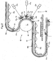
- Fig. 1 is a diagram of an overall configuration of an intaglio printing press shown as Example 1;
- Fig. 2 is a detailed drawing of an inspection section;
- Fig. 3 is a perspective view of a vacuum cylinder;
- Fig. 4 is a front cross-sectional view of the vacuum cylinder;
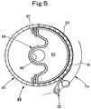
- Fig. 5 is a side cross-sectional view of the vacuum cylinder;
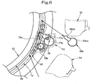
- Fig. 6 is an explanatory diagram of a delivery chain and a gripper unit;
- Fig. 7 is a control block diagram of a driving unit.
- an intaglio printing press mainly includes a feeding apparatus (sheet-shaped matter supplying apparatus) 10, a printing apparatus 20 and a delivery apparatus (sheet-shaped matter discharging unit) 40.
- the feeding apparatus 10 is loaded with sheets (sheet-shaped matters) W.
- a feedboard 11 communicates with the feeding apparatus 10.
- the feedboard 11 receives sheets W which are sent out from the top of the stack of sheets W by a sucker mechanism on a one-by-one basis.
- the feedboard 11 registers the sheet W.
- a swing arm shaft pre-gripper 12 is disposed next to the feedboard 11. The swing arm shaft pre-gripper 12 grips a sheet W situated on the feedboard 11, and swings with the sheet W being gripped.
- an impression cylinder 21 communicates with the swing arm shaft pre-gripper 12 with a transfer cylinder 22 being interposed therebetween.
- the impression cylinder 21 is so-called a triple-size cylinder.
- Three grippers can be placed on the impression cylinder at equal intervals in the circumferential direction, and three rubber-made blankets can be mounted to the impression cylinder 21.
- the impression cylinder 21 is supported by a frame 23.
- the transfer cylinder 22 includes grippers which are similar to the grippers of the impression cylinder 21.
- the grippers of the transfer cylinder 22 are configured to be capable of: gripping a sheet W from the swing arm shaft pre-gripper 12 in turn; and subsequently causing the grippers of the impression cylinder 21 to grip the sheet W in turn.
- a plate cylinder 24 is in contact with the impression cylinder 21.
- the plate cylinder 24 is so-called a triple-size cylinder.
- Three intaglio plates can be mounted on the plate cylinder 24 in the circumferential direction.
- the plate cylinder 24 is supported by the frame 23.
- An ink collecting cylinder 25 is in contact with the intaglio plates of the plate cylinder 24.
- the ink collecting cylinder 25 is so-called a quadruple-size cylinder.
- Four rubber-made blankets are mounted on the ink collecting cylinder 25 in the circumferential direction.
- the ink collecting cylinder 25 is supported by a frame 26.
- Each chablon roller 27 is so-called a monobloc roller.
- the circumferential length of each chablon roller 27 corresponds to the length of each blanket of the impression cylinder 21 and the length of each intaglio plate of the plate cylinder 24.
- Each chablon roller 27 is supported by the frame 26.
- Inking devices 28 are in contact with the respective chablon rollers 27. The inking devices 28 supply their respective inks.
- Each inking devices 28 are supported by a frame 29. Inks whose colors are different from one another are filled in the respective inking devices 28.
- the ink collecting cylinder 25 is the quadruple-size cylinder. Although the inking collecting cylinder 25 is very large, the inking collecting cylinder 25 is capable of being fully supported. That is because: the five chablon rollers 27 and the five inking devices are placed next to the ink collecting cylinder 25; and the ink collecting cylinder 25 and the chablon rollers 27 are supported by the frame 26 which is independent of the other frames.
- the ink collecting cylinder 25 is a triple-size cylinder, only four chablon rollers 27 and four inking devices 28 can be placed. If the ink collecting cylinder 25 is a quintuple-size or larger-size cylinder, the apparatus as a whole is too bulky. For these reasons, the quadruple-size cylinder is appropriate for the ink collecting cylinder 25. Furthermore, if the plate cylinder 24 is a double-size or smaller-size cylinder, it is difficult to install a wiping roller 30, which will be described later, and the like. If the plate cylinder 24 is a quadruple-size or larger-size cylinder, the apparatus is too bulky. For these reasons, the triple-size cylinder is appropriate for the plate cylinder 24.
- impression cylinder 21 and the plate cylinder 24 have different diameters, sheets W are likely to be printed out of register. For this reason, it is appropriate that the impression cylinder 21 should be the same triple-size cylinder, i.e., should have the same diameter as the plate cylinder 24.
- the wiping roller 30 is in contact with the intaglio plates of the plate cylinder 24. This wiping roller 30 is soaked in a wiping tank 31 containing a cleaning fluid.
- a delivery cylinder 41 is in contact with the impression cylinder 21.
- paired sprockets are coaxially provided to the delivery cylinder 41.
- Delivery chains (endless conveyance bodies) 42 are endlessly wound around the paired sprockets, respectively.
- a drying section 46, an inspection section 49 and a delivery section 51 are placed sequentially from the upstream to downstream in a running direction of these delivery chains 42.
- multiple dryers 44 four dryers 44 in the illustrated case
- vacuum tables 45 are installed in a way that the multiple dryers 44 are opposed to the vacuum tables 45 with the delivery chains 42 being interposed therebetween.
- Each dryer 44 includes a UV lamp 43 and the like.
- an inspection unit 47 and a vacuum cylinder 48 are installed in a way that the inspection unit 47 is opposed to the vacuum cylinder 48 with the delivery chains 42 being interposed therebetween.
- the inspection unit 47 includes multiple CCD-line cameras (three CCD-line cameras) 47a and the like.
- the delivery section 51 three delivery piles 50 are installed together. Note that, although described later, each delivery chain 42 is provided with gripper units (sheet-shaped matter holding units) 52 at equal intervals (see Figs. 2 and 6 ).
- an arc-shaped track portion (inwardly arc-shaped track portion) Ta is provided to a part of a movement track of each delivery chain 42 which runs under the guide of the a corresponding guide rail (chain guide) 53, in other words, a part of a movement track T of the gripper units 52.
- the arc-shaped track portion Ta is curved like the letter S, and thus projects toward the inside of a loop (closed space) formed by the movement track T. In other words, the arc center Oa of the arc-shaped track portion Ta is positioned outside the loop.
- the inspection unit 47 is installed in an opposite side of the arc-shaped track portion Ta from the arc center Oa of the arc-shaped track portion Ta, i.e., inside the loop.
- the vacuum cylinder 48 is installed at the same side of the arc-shaped track portion Ta as the arc center Oa, i.e., outside the loop.
- the inspection unit 47 includes the three CCD-cameras 47a, sources of light, and four air-blowing nozzles 55a to 55d.
- the three CCD-cameras 47a are arranged radially around the arc-shaped track portion Ta.
- the sources of light are LED illuminators, and are installed paired with the respective CCD-line cameras 47a.
- the four air-blowing nozzles 55a to 55d are installed around the arc-shaped track portion Ta at any intervals, and blow air to sheets W which run along the arc-shaped track portion Ta.
- reference signs 56a, 56b denote air-blowing guides; 57a to 57c denote vacuum guides; and 58a, 58b denote sheet guide plates.
- the vacuum cylinder 48 includes a porous cylindrical body 61 and a partition wall 64.
- the porous cylindrical body 61 is rotatably supported by a frame 59 with a bearing 60 being interposed between its cylinder shaft parts 61a and the frame 59.
- the circumferential surface of the porous cylindrical body 61 has a diameter in which the curvature of the circumferential surface is substantially equal to that of the arc-shaped track portion Ta.
- the partition wall 64 is housed in this porous cylindrical body 61.
- the partition wall 64 together with a seal member 62 defines a negative-pressure chamber 63.
- Negative pressure introducing pipes 65 extend out from the two sides of this partition wall 64, and penetrate the respective cylinder shaft parts 61a, thus projecting to the outside. Thereafter, the negative pressure introducing pipes 65 communicate with a source of negative pressure (a vacuum pump or the like) 66 with a pipe 66 being interposed between the source of negative pressure and each of the negative pressure introducing pipes 65.
- the negative pressure introducing pipes 65 are supported by the frame 59 with a bracket 67 being interposed between the frame 59 and each of the negative pressure introducing pipes 65. Openings of the negative-pressure chamber 63 are opposed to the front surface of each sheet W which runs along the arc-shaped track portion Te.
- a gear 68 is fastened to one of the cylinder shaft parts 61a.
- An output gear 70 of a vacuum cylinder motor (driving unit) 69 is in mesh with this gear 68.
- the circumferential speed of the vacuum cylinder 48 (exactly speaking, the porous cylindrical body 61) is designed to be adjustable, and can be changed to a circumferential speed which is appropriate to the speed of the sheet W.
- the drive of the vacuum cylinder motor (driving unit) 69 together with the drive of a driving motor (primary driving unit) 71 is controlled by control unit (control means) 72.
- a signal is inputted into the control unit 72 from each of paper information inputting means (sheet information inputting means) 73, a driving motor rotary encoder 74, and speed adjustment buttons (adjustment means) 75.
- the paper information inputting means 73 is configured to input information on a thickness of the sheet W, information on a material of the sheet W, and the like.
- the driving motor rotary encoder 74 is configured to detect a speed of the driving motor 71.
- the speed adjustment buttons (adjustment means) 75 are respectively configured to increase and decrease a circumferential speed of the vacuum cylinder 48 relative to the sheet W which run.
- a gripper pad shaft 77b is laid between paired brackets 78.
- a gripper shaft 76b and multiple gripper pads 77a are fastened to the gripper pad shaft 77b.
- the gripper shaft 76b supports multiple grippers 76a in a way that the multiple grippers 76a are capable of opening and closing (rotating).
- the brackets 78 are connected to the delivery chains 42 which run under the guidance of the guide rails 53, respectively.
- Fig. 6 shows each of the four air-blowing nozzles 55a to 55d that are obtained by installing multiple cylindrical nozzles 55bb on a nozzle header 55ba.
- each air-blowing nozzle 55a may be obtained by forming many nozzle holes in a pipe, or may be obtained by forming a slit in the pipe.
- sheets W are sent out from the feeding apparatus 10 to the top of the feedboard 11 on a one-by-one basis. Thereafter, each sheet W goes through the swing arm shaft pre-gripper 12 and the transfer cylinder 22. Subsequently, the sheet W is transferred to the grippers of the impression cylinder 21, and the grippers of the impression cylinder 21 grip the sheet W. Afterward, the sheet W is conveyed while gripped by the grippers of the impression cylinder 21. On the other hand, inks are transferred from the inking devices 28 to the ink collecting cylinder 25 via the chablon rollers 27, respectively. Thereby, the inks are supplied to top surfaces of the intaglio plates.
- the wiping roller 30 Excessive portions of the respective inks are removed by the wiping roller 30.
- the sheet W goes through the interstice between the impression cylinder 21 and the plate cylinder 24. Thereby, the inks are transferred to the sheet W, and the sheet W is thus printed.
- the printed sheet W is conveyed by the delivery chains 42 of the delivery apparatus 40 after going through the delivery cylinder 41. Subsequently, the sheet W is delivered to the top of a predetermined one of the delivery piles 50.
- the sheet W is inspected by the inspection unit 47 under the suction guidance of the vacuum cylinder 48 (exactly speaking, the porous cylindrical body 61) having a diameter in which the curvature of the circumferential surface of the vacuum cylinder 48 is substantially equal to that of the arc-shaped track portion Ta.
- the sheet W is conveyed stably, because: air is blown to the front surface of the sheet W from the four air-blowing nozzles 55a to 55d; and the porous cylindrical body 61 is rotationally driven at the circumferential speed which is appropriate to the speed of the sheet W.
- the porous cylindrical body 61 is placed at the same side of the arc-shaped track portion Ta as the arc center (curvature center) Oa. This placement allows the front ends of the respective grippers 76a in each gripper unit 52 to be placed as close to the suction surface of the porous cylindrical body 61 as possible.
- the inspection unit 47 is placed at the opposite side of the arc-shaped track portion Ta from the arc center Oa of the arc-shaped track portion Ta.
- the multiple CCD-line cameras 47a (the three CCD-line cameras in the illustrated example) and the like can be placed in compact inside the loop (closed space), which is formed by the movement track T of the gripper units 52, with no restriction. This allows different types of inspection to be effectively carried out.
- the CCD-cameras 47a can be placed horizontally. This placement is effective for protecting the camera lenses from foreign particles and duct.
- Fig. 8 is a detailed diagram of an inspection section as Example 2
- Fig. 9 is a perspective view of a suction box.
- a fixed suction guide 48A is used in a part of the arc-shaped track portion Ta in the inspection section 48.
- the fixed suction guide 48A has an arc-shaped suction surface 48a which is configured to cause each sheet W to stick to a part of its circumferential surface by suction.
- the curvature of the arc-shaped suction surface 48a is substantially equal to that of the arch-shaped track portion Ta.
- reference sign 48b denotes one of negative-pressure introducing pipes which extend out from the respective two sides of the fixed suction guide 48A.
- the fixed suction guide 48A is designed to be fixed to the frame 59 (see Fig. 4 ) by the negative-pressure introducing pipes 48b.
- the rest of the configuration of Example 2 is the same as the rest of the configuration of Example 1. For this reason, duplicated descriptions will be omitted.
- Example 2 Operation and working effects which are the same as those of Example 1 can be obtained from Example 2, except that the fixed suction guide 48A is not rotationally driven.
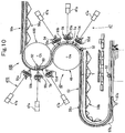
- Fig. 10 is a detailed diagram of an inspection section shown as Example 3 of the present invention.
- an inspection section 49B is additionally provided to the other (upper) arc-shaped track portion (outwardly arc-shaped track portion) Tb.
- a positional relationship of an inspection unit (external inspection unit) 47B and a vacuum cylinder (internal guide) 48B to their corresponding arc-shaped track potion is reverse to the positional relationship of the inspection unit 47 and the vacuum cylinder 48 to their corresponding arc-shaped track portion in the inspection section 49 which is situated under the inspection section 49B.
- the inspection unit 47B is placed at an opposite side of the arc-shaped track portion Tb from an arc center Ob of the arc-shaped track portion Tb (or outside the loop), whereas the vacuum cylinder 48B is placed at the same side of the arc-shaped track portion Tb as the arc center Ob side (or inside the loop).
- notches 80 which gripper units 52 are capable of entering, are formed in the outer circumference of the vacuum cylinder 48B.
- the rest of the configuration of this example is the same as the rest of the configuration of Example 1. For this reason, duplicated descriptions will be omitted.
- the inspection sections 49, 49B at the two locations enable multiple inspections whose types are more different from each other to be carried out.
- multiple CCD-line cameras (three CCD-line cameras in the illustrated case) 47a and the like can be placed in compact, too, outside the loop (closed space), which is formed by the movement track T of the gripper units 52, with no restriction. For this reason, this example is capable of effectively carrying out inspections whose types are different from each other.
- the fixed suction guides 48A of Example 2 may be used for the foregoing example.
- the present invention is not limited to be above-described examples; and the present invention can be variously modified within the scope of the present invention.
- belts may be used as the endless conveyance bodies.
- sprockets may be used as the guide unit for the endless conveyance bodies.
- the quality inspection apparatus according to the present invention can be preferably used as an intaglio printing press for printing bank notes, securities, and the like.
Landscapes
- Engineering & Computer Science (AREA)
- Mechanical Engineering (AREA)
- Quality & Reliability (AREA)
- Inking, Control Or Cleaning Of Printing Machines (AREA)
- Investigating Materials By The Use Of Optical Means Adapted For Particular Applications (AREA)
Claims (5)
- Qualitätsprüfvorrichtung für eine bogenförmige Sache, mit:Halteeinheiten (52) für eine bogenförmige Sache, mit denen jeder Endlostransportkörper (42) ausgestattet ist und die ausgestaltet sind, um einen Endbereich einer bogenförmigen Sache (W) zu halten;einem bogenförmigen Bahnabschnitt (Ta), mit dem ein Teil einer Bewegungsbahn (T) der Halteinheiten (52) für eine bogenförmige Sache ausgestattet ist;einer Führung (48), die auf einer selben Seite des bogenförmigen Bahnabschnitts (Ta) wie ein Bogenzentrum (Oa) installiert ist; undeiner Prüfeinheit (47), die in Bezug auf das Bogenzentrum (Oa) des bogenförmigen Bahnabschnitts (Ta) auf einer gegenüberliegenden Seite des bogenförmigen Bahnabschnitts (Ta) installiert ist, wobeidie bogenförmige Sache (W) von der Prüfeinheit (47) unter einer Führung der Führung (48) geprüft wird, während sie sich entlang des bogenförmigen Bahnabschnitts (Ta) bewegt;wobei der bogenförmige Bahnabschnitt (Ta) so installiert ist, dass er auf eine Innenseite einer durch die Bewegungsbahn (T) geformten Schleife zu konvex ist, damit das Bogenzentrum (Oa) des bogenförmigen Bahnabschnitts (Ta) außerhalb der Schleife positioniert ist, die Führung (48) außerhalb der Schleife installiert ist und die Prüfeinheit (47) innerhalb der Schleife installiert ist;dadurch gekennzeichnet,dass der bogenförmige Bahnabschnitt wie der Buchstabe S gekrümmt ist, was einen bogenförmigen Bahnabschnittsteil (Tb) einschließt, der so installiert ist, dass er auf eine Außenseite der von der Bewegungsbahn (T) gebildeten Schleife zu konvex ist, damit das Bogenzentrum (Ob) des bogenförmigen Bahnabschnittteils (Tb) innerhalb der Schleife positioniert ist;dass eine weitere Führung (46B) an einer Seite des Bahnabschnittsteils (Tb) innerhalb der Schleife installiert ist; unddass eine weitere Inspektionseinheit (47B) außerhalb der Schleife und an einer gegenüberliegenden Seite des Bahnabschnittteils (Tb) installiert ist.
- Qualitätsprüfvorrichtung für eine bogenförmige Sache nach Anspruch 1, dadurch gekennzeichnet, dass die Führung (48) ein drehend angetriebener drehbarer Führungskörper (48) ist, der einen derartigen Durchmesser hat, dass eine Umfangsfläche des drehbaren Führungskörpers (48) eine im Wesentlichen gleiche Krümmung zu derjenigen des bogenförmigen Bahnabschnitts (Ta) hat, wobei der drehbare Führungskörper (48) ausgestaltet ist, um zu bewirken, dass die bogenförmige Sache (W) durch Saugen an der Umfangsfläche haftet.
- Qualitätsprüfvorrichtung für eine bogenförmige Sache nach Anspruch 2, dadurch gekennzeichnet, dass der drehbare Führungskörper von einer exklusiven Antriebseinheit (69) drehend angetrieben wird.
- Qualitätsprüfvorrichtung für eine bogenförmige Sache nach Anspruch 2, dadurch gekennzeichnet, dass sie ferner eine Einstelleinrichtung (75) aufweist, die ausgestaltet ist, um eine Umfangsgeschwindigkeit des drehbaren Führungskörpers einzustellen.
- Qualitätsprüfvorrichtung für eine bogenförmige Sache nach Anspruch 3, dadurch gekennzeichnet, dass sie ferner aufweist:eine Bogeninformations-Eingabeeinrichtung (73), die ausgestaltet ist, um verschiedene Arten von Informationen über die bogenförmige Sache (W) einzugeben; undeine Steuereinrichtung (72), die ausgestaltet ist, um die Antriebseinheit (69) auf einer Basis eines Eingangssignals von der Bogeninformation-Eingabeeinrichtung (73) zu steuern.
Applications Claiming Priority (3)
| Application Number | Priority Date | Filing Date | Title |
|---|---|---|---|
| JP2009068122A JP2010223596A (ja) | 2009-03-19 | 2009-03-19 | シート状物の品質検査装置 |
| JP2009068121A JP5420944B2 (ja) | 2009-03-19 | 2009-03-19 | シート状物の搬送装置 |
| JP2009068120A JP5379525B2 (ja) | 2009-03-19 | 2009-03-19 | シート状物の品質検査装置 |
Publications (4)
| Publication Number | Publication Date |
|---|---|
| EP2230202A2 EP2230202A2 (de) | 2010-09-22 |
| EP2230202A3 EP2230202A3 (de) | 2012-01-25 |
| EP2230202B1 EP2230202B1 (de) | 2015-12-16 |
| EP2230202B2 true EP2230202B2 (de) | 2019-03-20 |
Family
ID=42246141
Family Applications (1)
| Application Number | Title | Priority Date | Filing Date |
|---|---|---|---|
| EP10156283.3A Active EP2230202B2 (de) | 2009-03-19 | 2010-03-12 | Qualitätsprüfvorrichtung für ein blattförmiges Material |
Country Status (3)
| Country | Link |
|---|---|
| US (1) | US8353246B2 (de) |
| EP (1) | EP2230202B2 (de) |
| CN (1) | CN101850652B (de) |
Families Citing this family (11)
| Publication number | Priority date | Publication date | Assignee | Title |
|---|---|---|---|---|
| EP2399745A1 (de) * | 2010-06-25 | 2011-12-28 | KBA-NotaSys SA | Inspektionssystem für Inline-Inspektion von auf einer Intaglio-Druckpresse hergestelltem Druckmaterial |
| JP2012161951A (ja) | 2011-02-04 | 2012-08-30 | Komori Corp | 証券印刷用オフセット印刷機 |
| CN102992058A (zh) * | 2011-09-14 | 2013-03-27 | 广州市奇先印刷设备有限公司 | 一种全自动放帖装置 |
| CN102680471B (zh) * | 2012-04-27 | 2015-01-21 | 深圳市中钞科信金融科技有限公司 | 一种基于输送链条的机器视觉检测装置及方法 |
| JP5959001B2 (ja) * | 2012-07-20 | 2016-08-02 | 株式会社小森コーポレーション | シート状物の検査装置 |
| JP6198291B2 (ja) * | 2012-08-03 | 2017-09-20 | 株式会社小森コーポレーション | シート案内装置及び該装置を備えたシート処理装置 |
| CN103868931B (zh) * | 2014-03-13 | 2017-03-15 | 武汉虹之彩包装印刷有限公司 | 用于连续识别镭射印刷品色相检测的吸附滚筒 |
| CN103837544B (zh) * | 2014-03-13 | 2016-04-20 | 武汉虹之彩包装印刷有限公司 | 印刷品连续检测用吸附滚筒对传送印刷品的调整方法 |
| CN105241892B (zh) * | 2015-11-20 | 2018-04-06 | 成都印钞有限公司 | 一种印品质量检测装置 |
| JP6757237B2 (ja) * | 2016-11-18 | 2020-09-16 | 株式会社Screenホールディングス | 搬送装置および印刷装置 |
| EP3715124A1 (de) | 2019-03-26 | 2020-09-30 | Inopaq Technologies Sàrl | Druckbogeninspektionssystem und bogendruckmaschine mit einem solchen druckbogeninspektionssystem |
Citations (2)
| Publication number | Priority date | Publication date | Assignee | Title |
|---|---|---|---|---|
| EP1142712A1 (de) † | 2000-04-07 | 2001-10-10 | Komori Corporation | Qualitätskontrolleinrichtung für eine beidseitige Druckmaschine |
| WO2008065693A1 (en) † | 2006-12-01 | 2008-06-05 | G.M.P. S.R.L. | Control device for numbering machines used to print numbers in ascending or descending order on bank notes, lottery tickets and value cards in general |
Family Cites Families (15)
| Publication number | Priority date | Publication date | Assignee | Title |
|---|---|---|---|---|
| IT1095199B (it) * | 1978-06-06 | 1985-08-10 | S F A Societa Di Fisica Applic | Macchina per il controllo automatico di qualita'su banconote e cartevalori di fresca stampa |
| JPS5956103A (ja) * | 1982-09-24 | 1984-03-31 | Toppan Printing Co Ltd | 画像面積率測定装置 |
| JPS6343852A (ja) | 1986-08-11 | 1988-02-24 | Mitsuba Electric Mfg Co Ltd | ワイパ装置 |
| DE9007513U1 (de) * | 1990-04-24 | 1992-03-12 | Heidelberger Druckmaschinen Ag, 6900 Heidelberg | Bogenleiteinrichtung im Auslegerbereich einer Bogenrotationsdruckmaschine |
| DE4126799A1 (de) | 1991-08-14 | 1993-02-18 | Koenig & Bauer Ag | Vorrichtung zum kontrollieren eines bedruckten bogens in einer bogenrotationsdruckmaschine |
| DE4239561C2 (de) * | 1992-11-25 | 2000-10-19 | Heidelberger Druckmasch Ag | Kettenförderer einer Bogendruckmaschine |
| DE59409290D1 (de) * | 1994-01-17 | 2000-05-18 | Heidelberger Druckmasch Ag | Bogenführungszylinder |
| DE19613084A1 (de) * | 1996-04-02 | 1997-10-09 | Koenig & Bauer Albert Ag | Saugkasten zum Führen von Bogen |
| JP4616451B2 (ja) * | 2000-09-22 | 2011-01-19 | 株式会社小森コーポレーション | 印刷品質検査装置 |
| JP4676070B2 (ja) * | 2001-02-09 | 2011-04-27 | 株式会社小森コーポレーション | 枚葉印刷機 |
| DE10128833B4 (de) * | 2001-06-15 | 2006-11-02 | Koenig & Bauer Ag | Qualitätskontrollvorrichtung |
| DE10207073B4 (de) * | 2002-02-20 | 2005-11-24 | Koenig & Bauer Ag | Vorrichtung zum Transport von Bogen mit einem Bogenleitelement |
| DE10222543B4 (de) * | 2002-05-17 | 2007-08-02 | Man Roland Druckmaschinen Ag | Auslegevorrichtung an einer Bogenverarbeitungsmaschine |
| JP2006069209A (ja) * | 2004-08-30 | 2006-03-16 | Heidelberger Druckmas Ag | 印刷技術的な機械を通ってシートを搬送する装置 |
| CN2920645Y (zh) * | 2006-04-29 | 2007-07-11 | 罗贤义 | 单张平版多色胶印机 |
-
2010
- 2010-03-12 EP EP10156283.3A patent/EP2230202B2/de active Active
- 2010-03-12 CN CN201010133050.9A patent/CN101850652B/zh not_active Expired - Fee Related
- 2010-03-18 US US12/726,435 patent/US8353246B2/en active Active
Patent Citations (2)
| Publication number | Priority date | Publication date | Assignee | Title |
|---|---|---|---|---|
| EP1142712A1 (de) † | 2000-04-07 | 2001-10-10 | Komori Corporation | Qualitätskontrolleinrichtung für eine beidseitige Druckmaschine |
| WO2008065693A1 (en) † | 2006-12-01 | 2008-06-05 | G.M.P. S.R.L. | Control device for numbering machines used to print numbers in ascending or descending order on bank notes, lottery tickets and value cards in general |
Also Published As
| Publication number | Publication date |
|---|---|
| CN101850652B (zh) | 2015-03-11 |
| US20100237560A1 (en) | 2010-09-23 |
| EP2230202B1 (de) | 2015-12-16 |
| CN101850652A (zh) | 2010-10-06 |
| EP2230202A2 (de) | 2010-09-22 |
| US8353246B2 (en) | 2013-01-15 |
| EP2230202A3 (de) | 2012-01-25 |
Similar Documents
| Publication | Publication Date | Title |
|---|---|---|
| EP2230202B2 (de) | Qualitätsprüfvorrichtung für ein blattförmiges Material | |
| JP5379525B2 (ja) | シート状物の品質検査装置 | |
| US8528477B2 (en) | Inspection system for a sheet-fed recto-verso printing press | |
| US8561987B2 (en) | Machine for processing sheets | |
| US6883429B2 (en) | Quality inspection apparatus for double-sided printing machine | |
| JP6022449B2 (ja) | 凹版印刷機で生成された印刷物をインライン検査するための検査システム | |
| JP4275211B2 (ja) | 枚葉紙輪転機 | |
| US6598872B1 (en) | Sheet braking device with replaceable support element | |
| JP2008275300A (ja) | シート状物の乾燥装置 | |
| JPWO2014065108A1 (ja) | 組合せ印刷機 | |
| US20150231877A1 (en) | Inspection system for inspecting the quality of printed sheets | |
| US20050242494A1 (en) | Apparatus for conveying sheets through a printing machine | |
| EP2692674B1 (de) | Bogenführungsvorrichtung und Bogenverarbeitungsvorrichtung umfassend die Bogenführungsvorrichtung | |
| JP5420944B2 (ja) | シート状物の搬送装置 | |
| JP2010223596A (ja) | シート状物の品質検査装置 | |
| JP2010194727A (ja) | 印刷機における乾燥装置 |
Legal Events
| Date | Code | Title | Description |
|---|---|---|---|
| PUAI | Public reference made under article 153(3) epc to a published international application that has entered the european phase |
Free format text: ORIGINAL CODE: 0009012 |
|
| AK | Designated contracting states |
Kind code of ref document: A2 Designated state(s): AT BE BG CH CY CZ DE DK EE ES FI FR GB GR HR HU IE IS IT LI LT LU LV MC MK MT NL NO PL PT RO SE SI SK SM TR |
|
| AX | Request for extension of the european patent |
Extension state: AL BA ME RS |
|
| PUAL | Search report despatched |
Free format text: ORIGINAL CODE: 0009013 |
|
| AK | Designated contracting states |
Kind code of ref document: A3 Designated state(s): AT BE BG CH CY CZ DE DK EE ES FI FR GB GR HR HU IE IS IT LI LT LU LV MC MK MT NL NO PL PT RO SE SI SK SM TR |
|
| AX | Request for extension of the european patent |
Extension state: AL BA ME RS |
|
| RIC1 | Information provided on ipc code assigned before grant |
Ipc: B41F 33/00 20060101ALI20111219BHEP Ipc: B65H 37/00 20060101ALI20111219BHEP Ipc: B65H 29/04 20060101AFI20111219BHEP |
|
| 17P | Request for examination filed |
Effective date: 20120724 |
|
| GRAP | Despatch of communication of intention to grant a patent |
Free format text: ORIGINAL CODE: EPIDOSNIGR1 |
|
| GRAJ | Information related to disapproval of communication of intention to grant by the applicant or resumption of examination proceedings by the epo deleted |
Free format text: ORIGINAL CODE: EPIDOSDIGR1 |
|
| GRAP | Despatch of communication of intention to grant a patent |
Free format text: ORIGINAL CODE: EPIDOSNIGR1 |
|
| INTG | Intention to grant announced |
Effective date: 20150630 |
|
| INTG | Intention to grant announced |
Effective date: 20150714 |
|
| GRAS | Grant fee paid |
Free format text: ORIGINAL CODE: EPIDOSNIGR3 |
|
| GRAA | (expected) grant |
Free format text: ORIGINAL CODE: 0009210 |
|
| AK | Designated contracting states |
Kind code of ref document: B1 Designated state(s): AT BE BG CH CY CZ DE DK EE ES FI FR GB GR HR HU IE IS IT LI LT LU LV MC MK MT NL NO PL PT RO SE SI SK SM TR |
|
| REG | Reference to a national code |
Ref country code: GB Ref legal event code: FG4D |
|
| REG | Reference to a national code |
Ref country code: CH Ref legal event code: EP Ref country code: CH Ref legal event code: NV Representative=s name: R.A. EGLI AND CO, PATENTANWAELTE, CH |
|
| REG | Reference to a national code |
Ref country code: IE Ref legal event code: FG4D |
|
| REG | Reference to a national code |
Ref country code: AT Ref legal event code: REF Ref document number: 765454 Country of ref document: AT Kind code of ref document: T Effective date: 20160115 |
|
| REG | Reference to a national code |
Ref country code: DE Ref legal event code: R096 Ref document number: 602010029461 Country of ref document: DE |
|
| REG | Reference to a national code |
Ref country code: NL Ref legal event code: MP Effective date: 20151216 |
|
| REG | Reference to a national code |
Ref country code: LT Ref legal event code: MG4D |
|
| PG25 | Lapsed in a contracting state [announced via postgrant information from national office to epo] |
Ref country code: LT Free format text: LAPSE BECAUSE OF FAILURE TO SUBMIT A TRANSLATION OF THE DESCRIPTION OR TO PAY THE FEE WITHIN THE PRESCRIBED TIME-LIMIT Effective date: 20151216 Ref country code: NO Free format text: LAPSE BECAUSE OF FAILURE TO SUBMIT A TRANSLATION OF THE DESCRIPTION OR TO PAY THE FEE WITHIN THE PRESCRIBED TIME-LIMIT Effective date: 20160316 Ref country code: HR Free format text: LAPSE BECAUSE OF FAILURE TO SUBMIT A TRANSLATION OF THE DESCRIPTION OR TO PAY THE FEE WITHIN THE PRESCRIBED TIME-LIMIT Effective date: 20151216 |
|
| REG | Reference to a national code |
Ref country code: AT Ref legal event code: MK05 Ref document number: 765454 Country of ref document: AT Kind code of ref document: T Effective date: 20151216 |
|
| PG25 | Lapsed in a contracting state [announced via postgrant information from national office to epo] |
Ref country code: NL Free format text: LAPSE BECAUSE OF FAILURE TO SUBMIT A TRANSLATION OF THE DESCRIPTION OR TO PAY THE FEE WITHIN THE PRESCRIBED TIME-LIMIT Effective date: 20151216 Ref country code: GR Free format text: LAPSE BECAUSE OF FAILURE TO SUBMIT A TRANSLATION OF THE DESCRIPTION OR TO PAY THE FEE WITHIN THE PRESCRIBED TIME-LIMIT Effective date: 20160317 Ref country code: SE Free format text: LAPSE BECAUSE OF FAILURE TO SUBMIT A TRANSLATION OF THE DESCRIPTION OR TO PAY THE FEE WITHIN THE PRESCRIBED TIME-LIMIT Effective date: 20151216 Ref country code: FI Free format text: LAPSE BECAUSE OF FAILURE TO SUBMIT A TRANSLATION OF THE DESCRIPTION OR TO PAY THE FEE WITHIN THE PRESCRIBED TIME-LIMIT Effective date: 20151216 Ref country code: LV Free format text: LAPSE BECAUSE OF FAILURE TO SUBMIT A TRANSLATION OF THE DESCRIPTION OR TO PAY THE FEE WITHIN THE PRESCRIBED TIME-LIMIT Effective date: 20151216 |
|
| REG | Reference to a national code |
Ref country code: DE Ref legal event code: R026 Ref document number: 602010029461 Country of ref document: DE |
|
| PG25 | Lapsed in a contracting state [announced via postgrant information from national office to epo] |
Ref country code: IT Free format text: LAPSE BECAUSE OF FAILURE TO SUBMIT A TRANSLATION OF THE DESCRIPTION OR TO PAY THE FEE WITHIN THE PRESCRIBED TIME-LIMIT Effective date: 20151216 Ref country code: CZ Free format text: LAPSE BECAUSE OF FAILURE TO SUBMIT A TRANSLATION OF THE DESCRIPTION OR TO PAY THE FEE WITHIN THE PRESCRIBED TIME-LIMIT Effective date: 20151216 Ref country code: ES Free format text: LAPSE BECAUSE OF FAILURE TO SUBMIT A TRANSLATION OF THE DESCRIPTION OR TO PAY THE FEE WITHIN THE PRESCRIBED TIME-LIMIT Effective date: 20151216 |
|
| PLBI | Opposition filed |
Free format text: ORIGINAL CODE: 0009260 |
|
| 26 | Opposition filed |
Opponent name: KOENIG & BAUER AG Effective date: 20160725 |
|
| PG25 | Lapsed in a contracting state [announced via postgrant information from national office to epo] |
Ref country code: SK Free format text: LAPSE BECAUSE OF FAILURE TO SUBMIT A TRANSLATION OF THE DESCRIPTION OR TO PAY THE FEE WITHIN THE PRESCRIBED TIME-LIMIT Effective date: 20151216 Ref country code: IS Free format text: LAPSE BECAUSE OF FAILURE TO SUBMIT A TRANSLATION OF THE DESCRIPTION OR TO PAY THE FEE WITHIN THE PRESCRIBED TIME-LIMIT Effective date: 20160416 Ref country code: EE Free format text: LAPSE BECAUSE OF FAILURE TO SUBMIT A TRANSLATION OF THE DESCRIPTION OR TO PAY THE FEE WITHIN THE PRESCRIBED TIME-LIMIT Effective date: 20151216 Ref country code: RO Free format text: LAPSE BECAUSE OF FAILURE TO SUBMIT A TRANSLATION OF THE DESCRIPTION OR TO PAY THE FEE WITHIN THE PRESCRIBED TIME-LIMIT Effective date: 20151216 Ref country code: SM Free format text: LAPSE BECAUSE OF FAILURE TO SUBMIT A TRANSLATION OF THE DESCRIPTION OR TO PAY THE FEE WITHIN THE PRESCRIBED TIME-LIMIT Effective date: 20151216 Ref country code: AT Free format text: LAPSE BECAUSE OF FAILURE TO SUBMIT A TRANSLATION OF THE DESCRIPTION OR TO PAY THE FEE WITHIN THE PRESCRIBED TIME-LIMIT Effective date: 20151216 Ref country code: BE Free format text: LAPSE BECAUSE OF NON-PAYMENT OF DUE FEES Effective date: 20160331 Ref country code: PT Free format text: LAPSE BECAUSE OF FAILURE TO SUBMIT A TRANSLATION OF THE DESCRIPTION OR TO PAY THE FEE WITHIN THE PRESCRIBED TIME-LIMIT Effective date: 20160418 |
|
| PLAX | Notice of opposition and request to file observation + time limit sent |
Free format text: ORIGINAL CODE: EPIDOSNOBS2 |
|
| PG25 | Lapsed in a contracting state [announced via postgrant information from national office to epo] |
Ref country code: MC Free format text: LAPSE BECAUSE OF FAILURE TO SUBMIT A TRANSLATION OF THE DESCRIPTION OR TO PAY THE FEE WITHIN THE PRESCRIBED TIME-LIMIT Effective date: 20151216 Ref country code: LU Free format text: LAPSE BECAUSE OF FAILURE TO SUBMIT A TRANSLATION OF THE DESCRIPTION OR TO PAY THE FEE WITHIN THE PRESCRIBED TIME-LIMIT Effective date: 20160312 Ref country code: PL Free format text: LAPSE BECAUSE OF FAILURE TO SUBMIT A TRANSLATION OF THE DESCRIPTION OR TO PAY THE FEE WITHIN THE PRESCRIBED TIME-LIMIT Effective date: 20151216 Ref country code: DK Free format text: LAPSE BECAUSE OF FAILURE TO SUBMIT A TRANSLATION OF THE DESCRIPTION OR TO PAY THE FEE WITHIN THE PRESCRIBED TIME-LIMIT Effective date: 20151216 |
|
| GBPC | Gb: european patent ceased through non-payment of renewal fee |
Effective date: 20160316 |
|
| REG | Reference to a national code |
Ref country code: IE Ref legal event code: MM4A |
|
| PG25 | Lapsed in a contracting state [announced via postgrant information from national office to epo] |
Ref country code: BE Free format text: LAPSE BECAUSE OF FAILURE TO SUBMIT A TRANSLATION OF THE DESCRIPTION OR TO PAY THE FEE WITHIN THE PRESCRIBED TIME-LIMIT Effective date: 20151216 |
|
| REG | Reference to a national code |
Ref country code: FR Ref legal event code: ST Effective date: 20161130 |
|
| PG25 | Lapsed in a contracting state [announced via postgrant information from national office to epo] |
Ref country code: FR Free format text: LAPSE BECAUSE OF NON-PAYMENT OF DUE FEES Effective date: 20160331 Ref country code: IE Free format text: LAPSE BECAUSE OF NON-PAYMENT OF DUE FEES Effective date: 20160312 Ref country code: GB Free format text: LAPSE BECAUSE OF NON-PAYMENT OF DUE FEES Effective date: 20160316 |
|
| PG25 | Lapsed in a contracting state [announced via postgrant information from national office to epo] |
Ref country code: SI Free format text: LAPSE BECAUSE OF FAILURE TO SUBMIT A TRANSLATION OF THE DESCRIPTION OR TO PAY THE FEE WITHIN THE PRESCRIBED TIME-LIMIT Effective date: 20151216 |
|
| PLBB | Reply of patent proprietor to notice(s) of opposition received |
Free format text: ORIGINAL CODE: EPIDOSNOBS3 |
|
| PG25 | Lapsed in a contracting state [announced via postgrant information from national office to epo] |
Ref country code: MT Free format text: LAPSE BECAUSE OF FAILURE TO SUBMIT A TRANSLATION OF THE DESCRIPTION OR TO PAY THE FEE WITHIN THE PRESCRIBED TIME-LIMIT Effective date: 20151216 |
|
| PG25 | Lapsed in a contracting state [announced via postgrant information from national office to epo] |
Ref country code: CY Free format text: LAPSE BECAUSE OF FAILURE TO SUBMIT A TRANSLATION OF THE DESCRIPTION OR TO PAY THE FEE WITHIN THE PRESCRIBED TIME-LIMIT Effective date: 20151216 Ref country code: HU Free format text: LAPSE BECAUSE OF FAILURE TO SUBMIT A TRANSLATION OF THE DESCRIPTION OR TO PAY THE FEE WITHIN THE PRESCRIBED TIME-LIMIT; INVALID AB INITIO Effective date: 20100312 |
|
| PG25 | Lapsed in a contracting state [announced via postgrant information from national office to epo] |
Ref country code: MT Free format text: LAPSE BECAUSE OF FAILURE TO SUBMIT A TRANSLATION OF THE DESCRIPTION OR TO PAY THE FEE WITHIN THE PRESCRIBED TIME-LIMIT Effective date: 20160331 Ref country code: MK Free format text: LAPSE BECAUSE OF FAILURE TO SUBMIT A TRANSLATION OF THE DESCRIPTION OR TO PAY THE FEE WITHIN THE PRESCRIBED TIME-LIMIT Effective date: 20151216 Ref country code: TR Free format text: LAPSE BECAUSE OF FAILURE TO SUBMIT A TRANSLATION OF THE DESCRIPTION OR TO PAY THE FEE WITHIN THE PRESCRIBED TIME-LIMIT Effective date: 20151216 |
|
| PG25 | Lapsed in a contracting state [announced via postgrant information from national office to epo] |
Ref country code: BG Free format text: LAPSE BECAUSE OF FAILURE TO SUBMIT A TRANSLATION OF THE DESCRIPTION OR TO PAY THE FEE WITHIN THE PRESCRIBED TIME-LIMIT Effective date: 20151216 |
|
| PUAH | Patent maintained in amended form |
Free format text: ORIGINAL CODE: 0009272 |
|
| STAA | Information on the status of an ep patent application or granted ep patent |
Free format text: STATUS: PATENT MAINTAINED AS AMENDED |
|
| REG | Reference to a national code |
Ref country code: CH Ref legal event code: AELC |
|
| 27A | Patent maintained in amended form |
Effective date: 20190320 |
|
| AK | Designated contracting states |
Kind code of ref document: B2 Designated state(s): AT BE BG CH CY CZ DE DK EE ES FI FR GB GR HR HU IE IS IT LI LT LU LV MC MK MT NL NO PL PT RO SE SI SK SM TR |
|
| REG | Reference to a national code |
Ref country code: DE Ref legal event code: R102 Ref document number: 602010029461 Country of ref document: DE |
|
| PGFP | Annual fee paid to national office [announced via postgrant information from national office to epo] |
Ref country code: DE Payment date: 20240130 Year of fee payment: 15 |
|
| PGFP | Annual fee paid to national office [announced via postgrant information from national office to epo] |
Ref country code: CH Payment date: 20240401 Year of fee payment: 15 |