EP2228613A2 - Lineare Wärmetauscher und Verfahren zu deren Herstellung - Google Patents
Lineare Wärmetauscher und Verfahren zu deren Herstellung Download PDFInfo
- Publication number
- EP2228613A2 EP2228613A2 EP10156542A EP10156542A EP2228613A2 EP 2228613 A2 EP2228613 A2 EP 2228613A2 EP 10156542 A EP10156542 A EP 10156542A EP 10156542 A EP10156542 A EP 10156542A EP 2228613 A2 EP2228613 A2 EP 2228613A2
- Authority
- EP
- European Patent Office
- Prior art keywords
- tubing
- length
- heat exchanger
- channels
- lengths
- Prior art date
- Legal status (The legal status is an assumption and is not a legal conclusion. Google has not performed a legal analysis and makes no representation as to the accuracy of the status listed.)
- Withdrawn
Links
- 238000000034 method Methods 0.000 title description 13
- 239000012530 fluid Substances 0.000 claims description 25
- 238000004378 air conditioning Methods 0.000 claims description 9
- 239000007788 liquid Substances 0.000 description 15
- 239000003507 refrigerant Substances 0.000 description 12
- ORQBXQOJMQIAOY-UHFFFAOYSA-N nobelium Chemical compound [No] ORQBXQOJMQIAOY-UHFFFAOYSA-N 0.000 description 6
- 238000010276 construction Methods 0.000 description 5
- 238000012986 modification Methods 0.000 description 5
- 230000004048 modification Effects 0.000 description 5
- 238000012546 transfer Methods 0.000 description 5
- PXHVJJICTQNCMI-UHFFFAOYSA-N Nickel Chemical compound [Ni] PXHVJJICTQNCMI-UHFFFAOYSA-N 0.000 description 4
- 238000001816 cooling Methods 0.000 description 4
- 239000000463 material Substances 0.000 description 4
- 239000002585 base Substances 0.000 description 3
- 230000015572 biosynthetic process Effects 0.000 description 3
- 238000004519 manufacturing process Methods 0.000 description 3
- 238000005057 refrigeration Methods 0.000 description 3
- 238000011144 upstream manufacturing Methods 0.000 description 3
- RYGMFSIKBFXOCR-UHFFFAOYSA-N Copper Chemical compound [Cu] RYGMFSIKBFXOCR-UHFFFAOYSA-N 0.000 description 2
- 229910045601 alloy Inorganic materials 0.000 description 2
- 239000000956 alloy Substances 0.000 description 2
- 229910052782 aluminium Inorganic materials 0.000 description 2
- XAGFODPZIPBFFR-UHFFFAOYSA-N aluminium Chemical compound [Al] XAGFODPZIPBFFR-UHFFFAOYSA-N 0.000 description 2
- 229910052802 copper Inorganic materials 0.000 description 2
- 239000010949 copper Substances 0.000 description 2
- 238000010586 diagram Methods 0.000 description 2
- 229910052759 nickel Inorganic materials 0.000 description 2
- 229910000831 Steel Inorganic materials 0.000 description 1
- 238000002788 crimping Methods 0.000 description 1
- 238000013461 design Methods 0.000 description 1
- 230000000694 effects Effects 0.000 description 1
- 239000000446 fuel Substances 0.000 description 1
- 230000005484 gravity Effects 0.000 description 1
- 229910052751 metal Inorganic materials 0.000 description 1
- 239000002184 metal Substances 0.000 description 1
- 150000002739 metals Chemical class 0.000 description 1
- 230000000717 retained effect Effects 0.000 description 1
- 238000012552 review Methods 0.000 description 1
- 229920006395 saturated elastomer Polymers 0.000 description 1
- 238000007789 sealing Methods 0.000 description 1
- 239000010935 stainless steel Substances 0.000 description 1
- 229910001220 stainless steel Inorganic materials 0.000 description 1
- 239000010959 steel Substances 0.000 description 1
- 238000003860 storage Methods 0.000 description 1
- 238000006467 substitution reaction Methods 0.000 description 1
Images




Classifications
-
- B—PERFORMING OPERATIONS; TRANSPORTING
- B21—MECHANICAL METAL-WORKING WITHOUT ESSENTIALLY REMOVING MATERIAL; PUNCHING METAL
- B21D—WORKING OR PROCESSING OF SHEET METAL OR METAL TUBES, RODS OR PROFILES WITHOUT ESSENTIALLY REMOVING MATERIAL; PUNCHING METAL
- B21D39/00—Application of procedures in order to connect objects or parts, e.g. coating with sheet metal otherwise than by plating; Tube expanders
- B21D39/04—Application of procedures in order to connect objects or parts, e.g. coating with sheet metal otherwise than by plating; Tube expanders of tubes with tubes; of tubes with rods
- B21D39/048—Application of procedures in order to connect objects or parts, e.g. coating with sheet metal otherwise than by plating; Tube expanders of tubes with tubes; of tubes with rods using presses for radially crimping tubular elements
-
- B—PERFORMING OPERATIONS; TRANSPORTING
- B21—MECHANICAL METAL-WORKING WITHOUT ESSENTIALLY REMOVING MATERIAL; PUNCHING METAL
- B21D—WORKING OR PROCESSING OF SHEET METAL OR METAL TUBES, RODS OR PROFILES WITHOUT ESSENTIALLY REMOVING MATERIAL; PUNCHING METAL
- B21D15/00—Corrugating tubes
- B21D15/02—Corrugating tubes longitudinally
-
- B—PERFORMING OPERATIONS; TRANSPORTING
- B21—MECHANICAL METAL-WORKING WITHOUT ESSENTIALLY REMOVING MATERIAL; PUNCHING METAL
- B21D—WORKING OR PROCESSING OF SHEET METAL OR METAL TUBES, RODS OR PROFILES WITHOUT ESSENTIALLY REMOVING MATERIAL; PUNCHING METAL
- B21D53/00—Making other particular articles
- B21D53/02—Making other particular articles heat exchangers or parts thereof, e.g. radiators, condensers fins, headers
- B21D53/06—Making other particular articles heat exchangers or parts thereof, e.g. radiators, condensers fins, headers of metal tubes
-
- F—MECHANICAL ENGINEERING; LIGHTING; HEATING; WEAPONS; BLASTING
- F25—REFRIGERATION OR COOLING; COMBINED HEATING AND REFRIGERATION SYSTEMS; HEAT PUMP SYSTEMS; MANUFACTURE OR STORAGE OF ICE; LIQUEFACTION SOLIDIFICATION OF GASES
- F25B—REFRIGERATION MACHINES, PLANTS OR SYSTEMS; COMBINED HEATING AND REFRIGERATION SYSTEMS; HEAT PUMP SYSTEMS
- F25B40/00—Subcoolers, desuperheaters or superheaters
-
- F—MECHANICAL ENGINEERING; LIGHTING; HEATING; WEAPONS; BLASTING
- F28—HEAT EXCHANGE IN GENERAL
- F28D—HEAT-EXCHANGE APPARATUS, NOT PROVIDED FOR IN ANOTHER SUBCLASS, IN WHICH THE HEAT-EXCHANGE MEDIA DO NOT COME INTO DIRECT CONTACT
- F28D7/00—Heat-exchange apparatus having stationary tubular conduit assemblies for both heat-exchange media, the media being in contact with different sides of a conduit wall
- F28D7/10—Heat-exchange apparatus having stationary tubular conduit assemblies for both heat-exchange media, the media being in contact with different sides of a conduit wall the conduits being arranged one within the other, e.g. concentrically
- F28D7/106—Heat-exchange apparatus having stationary tubular conduit assemblies for both heat-exchange media, the media being in contact with different sides of a conduit wall the conduits being arranged one within the other, e.g. concentrically consisting of two coaxial conduits or modules of two coaxial conduits
-
- F—MECHANICAL ENGINEERING; LIGHTING; HEATING; WEAPONS; BLASTING
- F28—HEAT EXCHANGE IN GENERAL
- F28F—DETAILS OF HEAT-EXCHANGE AND HEAT-TRANSFER APPARATUS, OF GENERAL APPLICATION
- F28F1/00—Tubular elements; Assemblies of tubular elements
- F28F1/02—Tubular elements of cross-section which is non-circular
- F28F1/06—Tubular elements of cross-section which is non-circular crimped or corrugated in cross-section
-
- F—MECHANICAL ENGINEERING; LIGHTING; HEATING; WEAPONS; BLASTING
- F28—HEAT EXCHANGE IN GENERAL
- F28F—DETAILS OF HEAT-EXCHANGE AND HEAT-TRANSFER APPARATUS, OF GENERAL APPLICATION
- F28F1/00—Tubular elements; Assemblies of tubular elements
- F28F1/08—Tubular elements crimped or corrugated in longitudinal section
-
- F—MECHANICAL ENGINEERING; LIGHTING; HEATING; WEAPONS; BLASTING
- F25—REFRIGERATION OR COOLING; COMBINED HEATING AND REFRIGERATION SYSTEMS; HEAT PUMP SYSTEMS; MANUFACTURE OR STORAGE OF ICE; LIQUEFACTION SOLIDIFICATION OF GASES
- F25B—REFRIGERATION MACHINES, PLANTS OR SYSTEMS; COMBINED HEATING AND REFRIGERATION SYSTEMS; HEAT PUMP SYSTEMS
- F25B2500/00—Problems to be solved
- F25B2500/01—Geometry problems, e.g. for reducing size
-
- Y—GENERAL TAGGING OF NEW TECHNOLOGICAL DEVELOPMENTS; GENERAL TAGGING OF CROSS-SECTIONAL TECHNOLOGIES SPANNING OVER SEVERAL SECTIONS OF THE IPC; TECHNICAL SUBJECTS COVERED BY FORMER USPC CROSS-REFERENCE ART COLLECTIONS [XRACs] AND DIGESTS
- Y10—TECHNICAL SUBJECTS COVERED BY FORMER USPC
- Y10T—TECHNICAL SUBJECTS COVERED BY FORMER US CLASSIFICATION
- Y10T29/00—Metal working
- Y10T29/49—Method of mechanical manufacture
- Y10T29/4935—Heat exchanger or boiler making
- Y10T29/49361—Tube inside tube
Definitions
- the present invention relates to tube-in-tube style, in-line heat exchangers and their manufacture.
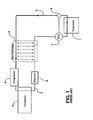
- Conventional refrigeration systems continuously circulate refrigerant in an evaporator and a condenser in a closed system such as shown in the simplified diagram of FIG. 1 .
- These systems have a high-pressure side (indicated by the thin lines 2 ) and a low-pressure side (indicated by the thick lines 3 ).
- a supply of low-pressure refrigerant liquid expands, absorbs heat, and evaporates, changing to a low-pressure, saturated, dry gas.
- a compressor 4 draws this gas from the evaporator 1 through a suction line (3).
- Compressor 4 increases the pressure of the gas, and discharges the high-pressure and high temperature refrigerant gas to a condenser 5 through a discharge line. Heat is removed from the gas at the condenser 5, which gas then condenses and becomes a high-pressure liquid.
- the high-pressure refrigerant liquid flows from the condenser 5 into a receiver tank 6. From the receiver 6 the high-pressure refrigerant liquid flows toward the evaporator 1 in a pipe called the liquid line. In order for the refrigerant liquid to evaporate and cool the fluid needing refrigeration, its pressure must be reduced. This pressure reduction is achieved by passing the high-pressure refrigerant liquid through a flow restrictor (also called an expansion device).
- TXV thermal expansion valve 7
- sensor 9 operatively connected (shown in dotted line) thereto, the temperature at the refrigerant vapor outlet of the evaporator.
- the flow of refrigerant into the evaporator 1 is controlled by the degree of superheat of the suction gas.
- a heat exchanger 8 (depicted in dashed lines) between the liquid line and the suction line is also conventionally provided to facilitate cooling of the high-pressure and high-temperature liquid by moving it in close proximity to, and flowing oppositely of, he low-pressure and low-temperature gas drawn from the evaporator 1.
- heat exchangers comprise tubing made up of concentric inner and outer tubes. According to this construction, also referred to as a tube-in-tube style heat exchanger, the high-pressure, high-temperature liquid is caused to flow through the annular space between the inner and outer tubes, while evaporated low-pressure, low-temperature refrigerant gas is caused to flow through the inside of the inner tube of the heat exchanger.
- the high-pressure, high-temperature liquid and the low-pressure, low-temperature gas exchange heat through the inner tube, whereby the high-pressure, high-temperature liquid is cooled.
- This heat transfer process of the high-pressure and high-temperature liquid increases the sub-cooling thereof.
- an in-line heat exchanger comprising first and second lengths of seamless, walled tubing, the first length of tubing characterized by a larger diameter than the diameter of the second length of tubing, and the second length of walled tubing disposed within the first length of walled tubing.
- a plurality of longitudinally-extending channels defined in the wall of at least one of the first and second lengths of tubing, the channels defining therebetween a plurality of longitudinally-extending passageways in the area between the walls of the first and second lengths of tubing.
- Terminal portions provided at opposite ends of the first length of tubing are each sealed with respect to the second length of tubing, and each defines one of an inlet or an outlet.
- Each terminal portion further defines at least one interior passageway between the terminal portion and the wall of the second length of tubing, the at least one interior passageway communicating the plurality of longitudinally-extending passageways with one of the inlet or outlet.
- the terminal portions may each be defined by opposite ends of the first length of tubing that are sealed against the wall of the second length of tubing.
- the terminal portions comprise separate lengths of tubing that are connected to each of the first and second lengths of tubing.
- the terminal portions may have different longitudinal dimensions with respect to each other so as to define interior passageways of different volumes. Furthermore, one of the terminal portions may define an interior passageway capable of accommodating an amount of a high-pressure, sub-cooled fluid at least equivalent to the weight of the quantity of a high-pressure fluid that can be accommodated in the receiver dryer in a fully charged air-conditioning system.
- the plurality of longitudinally-extending channels may be defined in only the wall of the first length of tubing. However, the plurality of longitudinally-extending channels may, alternatively, be defined in the wall of only the second length of tubing, or in the walls of both of the first and second lengths of tubing.
- the plurality of longitudinally extending channels may comprise at least two discrete sets of longitudinally extending channels. Each discrete set of channels may, moreover, be separated from the other by an intermediate space defined in the area between the walls of the first and second lengths of tubing. At least one such discrete set of channels may be offset relative to the one or more other sets of channels.
- the plurality of longitudinally-extending channels may each define a helical path.
- a method for forming in-line heat exchangers comprising the steps of: providing at least first and second lengths of seamless, walled tubing, the first length of tubing characterized by a larger diameter than the diameter of the second length of tubing, and each of the at least first and second lengths of walled tubing characterized by generally circular cross-sectional shapes; inwardly deforming circumferentially spaced-apart portions of the wall of at least one of the first and second lengths of tubing to form along a longitudinal length thereof a plurality of longitudinally-extending channels; and positioning the second length of walled tubing within the first length of walled tubing so that the walls of the first and second lengths of tubing are in contact proximate the plurality of longitudinally-extending channels, and so that, intermediate the areas of contact between the first and second lengths of walled tubing proximate the plurality of longitudinally-extending channels there are defined between the walls of the first and second lengths of tub
- the method may include the step of positioning the second length of walled tubing within the first length of walled tubing is carried out before the step of inwardly deforming circumferentially spaced-apart portions of the wall of at least one of the first and second lengths of tubing.
- the method may include the step of positioning the second length of walled tubing within the first length of walled tubing is carried out after the step of inwardly deforming circumferentially spaced-apart portions of the wall of at least one of the first and second lengths of tubing.
- the method may include the step of inwardly deforming circumferentially spaced-apart portions of the wall of at least one of the first and second lengths of tubing comprises inwardly deforming circumferentially spaced apart portions of the wall of the second length of tubing.
- the method may include the step of inwardly deforming circumferentially spaced-apart portions of the wall of at least one of the first and second lengths of tubing comprises inwardly deforming circumferentially spaced apart portions of the walls of the first and second lengths of tubing.
- the method may include the step of inwardly deforming circumferentially spaced-apart portions of the wall of at least one of the first and second lengths of tubing to form along a longitudinal length thereof a plurality of longitudinally-extending channels further comprises forming those channels intermediate of terminal sections of the first length of tubing, and wherein the method further comprises the step of sealing the ends of the terminal sections against the wall of the second length of tubing to define terminal portions each defining at least one interior passageway between the terminal portion and the wall of the second length of tubing, the at least one interior passageway communicating the plurality of longitudinally-extending passageways, and the step of forming one of an inlet or outlet passageway in each terminal section, the inlet and outlet each communicating one or the other of the at least one interior passageways defined in each terminal portion.
- the terminal portions may have different longitudinal dimensions with respect to each other so as to define interior passageways of different volumes.
- One of the terminal portions may define an interior passageway capable of accommodating an amount of a high-pressure, sub-cooled fluid at least equivalent to the weight of the quantity of a high-pressure fluid that can be accommodated in the receiver dryer in a fully-charged air-conditioning system.
- the plurality of longitudinally-extending channels may comprise at least two discrete sets of channels, each discrete set of channels comprising a plurality of longitudinally-extending channels.
- At least one discrete set of channels may be offset relative to the one or more other discrete sets of channels.
- Each such discrete set of channels may be separated from the other by an intermediate space defined in the area between the walls of the first and second lengths of tubing.
- the plurality of longitudinally extending channels may each define a helical path.
- the present invention is characterized, according to a first embodiment thereof, as a tube-in-tube style, inline heat exchanger (identified generally at 10 ) comprising first 20 and second 30 lengths of walled tubing arranged with the second length 30 of tubing disposed within the inner diameter of the first length 20 of tubing.
- FIGS. 2A and 2B While generally described herein in connection with air conditioning systems, it will be understood by those skilled in the art that the heat exchanger of the present invention may be incorporated in any system employing a two-phase refrigerant fluid.
- the second length 30 of tubing is characterized by a generally circular cross-section, with the area 31 defined by the inner diameter defining a passageway for the flow of a low-pressure, low-temperature fluid, such as a refrigerant gas, therethrough.
- the first length 20 of tubing is characterized by a corrugated or wavy cross-section defined by a plurality of circumferentially spaced-apart, longitudinally-extending channels 21. Proximate the nadir of each such channel 21, the inner surface of the wall of the outer, first length 20 of tubing is in contact with the exterior surface of the wall of the inner, second length 30 of tubing.
- each passageway 40 defines an internal channel for the flow of a high-pressure fluid, such as a high-pressure liquid, therethrough in a direction opposite the direction of the low-pressure fluid flow through the inner diameter 31 of the second length of tubing 30.
- a high-pressure fluid such as a high-pressure liquid
- the heat exchanger will, in order to be integrated in-line into a refrigeration system (such as depicted in schematically in FIG. 3 ) or other operational environment, include terminal portions 22a, 22b disposed exteriorly of, and sealed with respect to, the second length of tubing 30, as shown in FIG. 2A (where the second length of tubing 30 is shown in dashed lines).
- Each terminal portion 22a, 22b communicates a passageway 23a, 23b, respectively, defining one of an inlet or an outlet for a high-pressure fluid (such as for a high-pressure liquid in a vehicle air-conditioning system) with, respectively, at least one interior passageway 24a or 24b (such as, for instance, a circumferential space) defined in the area between the terminal portion and the wall of the second length of tubing 30.
- a high-pressure fluid such as for a high-pressure liquid in a vehicle air-conditioning system
- interior passageway 24a such as, for instance, a circumferential space
- the number of passageways 40 and their individual cross-sectional dimensions, as well as the dimensions of the inner diameter 31 of the second length of tubing 30, and the thickness of the walls of each of the first 20 and second 30 lengths of tubing will vary in accordance with the type of two-phase fluids employed in, and other known operating parameters of, the system. Generally speaking, however, it is contemplated that the number of passageways 40 and their individual cross-sectional dimensions will correspond to the cross-sectional dimensions of the interior passageways 24a or 24b defined in the area between the terminal portions 22a, 22b, respectively, and the exterior of the wall of the second length of tubing 30.
- the length of the active heat-transfer area - that is, the length of the portion of heat-exchanger 10 comprising channels 21 and corresponding passageways 40 - will vary according to the particular parameters (e.g., air conditioner size and cooling load) of the system in which it is incorporated.
- the heat exchanger 10 depicted in the several embodiments disclosed herein is straight, it will be understood that the tubing may be bent -- typically along the length of the active heat transfer surface -- as required to accommodate the physical limitations of the space in which the heat exchanger 10 is disposed, to make necessary connections between the opposite ends of the second length of tubing 30, etc.
- the heat exchanger as disclosed herein has demonstrated the ability to be bent in multiple locations without collapsing the passageways 40.
- the second length of tubing 30 extends beyond the terminal portions 22a, 22b .
- the length of these extensions will vary according to the particular application and, in any known manner, the opposite free ends of the second length 30 of tubing may be secured to. upstream and downstream components in the system in which the heat-exchanger is employed.
- the terminal portions 22a, 22b may, as shown, be formed from terminal sections of the first length of tubing 20 that are not formed with channels 21 (so that the high-pressure fluid can move freely from the inlet into each of the passageways 40 and, at the opposite end of each of these passageways 40, may likewise move freely to the outlet). This may be accomplished, for example, by crimping the ends 25a, 25b against the second length of tubing 30. The crimped ends 25a, 25b may be brazed or otherwise sealed by conventional means against the tubing 30 so that high-pressure fluid is able to move only between the inlet and outlets of terminal portions 22a, 22b.
- the terminal portions may comprise separate lengths of tubing that are connected to each of the first and second lengths of tubing.
- suitable exemplary materials include metals such as steel, stainless steel, aluminum, aluminum base, copper, copper base alloys and nickel and nickel base alloys.
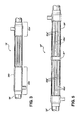
- FIGS. 3 and 4 there is shown an alternative embodiment wherein the heat exchanger 10' is characterized by terminal portions 22a', 22b' of dissimilar longitudinal dimensions. More particularly, the terminal portion at which the outlet is defined ( 22b' in the illustrated example) has relatively greater longitudinal dimensions than the terminal portion at which the inlet is defined ( 22a' in the example).
- the longitudinal dimension of terminal portion 22b' is such that the volume of the interior passageway 24b' defined in the area between the terminal portion 22b' and the exterior of the wall of the second length of tubing 30' is capable of accommodating, by weight (e.g., in grams), an amount of high-pressure, high-temperature fluid at least equivalent to the weight (e.g., in grams) of the quantity of high-pressure, high-temperature fluid that can be accommodated in the receiver dryer (whether integrated with the condenser or of the stand-alone type) in a fully-charged vehicle air conditioning system.
- the outlet to the thermal expansion valve 7 is oriented to provide gravity feed of sub-cooled, high-pressure fluid thereto. Such orientation in particular serves to reduce noise at the thermal expansion valve.
- the inventive heat exchanger provides a fluid storage capability and, moreover, the sub-cooled fluid metered to the thermal expansion valve 7 is characterized by a lower pressure drop than in conventional systems. This improves vehicle fuel economy (when employed in a vehicle air-conditioning system), increases the cooling capacity of the evaporator, and permits relocation or even removal of the receiver dryer or integrated receiver found in conventional vehicle air-conditioning systems.
- heat exchanger 10 may have formed therein a plurality of longitudinally discontinuous channels 21 a", 21 b" that are interrupted one or more times along the length of the tubing 20" to define therebetween, and in the area between the first 20" and second 30" lengths of tubing, one or more intermediate spaces 41" in which high-pressure, high-temperature fluid exiting the passageways 40a" would flow before entering further, downstream passageways 40b". It will be understood that such intermediate spaces 41" beneficially facilitate mixing of the fluid flowing therein.
- the channels 21a"', 21b"', 21c"' are longitudinally discontinuous, being interrupted by one or more intermediate spaces 41a"', 41b"' , with the successive set of channels 21b"' , 21c"' (and, therefore, downstream passageways, e.g., 40b"', 40c”' ) being offset relative to each preceding set of channels 21a"', 21b"' (and, therefore, upstream passageways, e.g., 40a"', 40b”' ).
- the intermediate spaces 41a"' , 41 b"' of this embodiment are of shorter longitudinal dimensions than those of the embodiment of FIG. 5 . It will be appreciated that the length of such intermediate spaces may be varied as desired, subject only to the provision that fluid flowing through one set of upstream passageways be able to continue flowing into successive downstream passageways.
- any number of sets of such discontinuous channels, whether aligned or offset, may be provided, depending upon the length of the channels in such sets and the overall length of the heat exchanger.
- the channels 21"" may be formed so as to each define a helical path along the length of the first length of tubing 20"" between the terminal portions 22a"" , 22b"".
- the heat exchanger 10"" of this embodiment may be further characterized by longitudinally discontinuous channels, such as exemplified in foregoing embodiments, and one or more intermediate spaces (not shown) disposed therebetween.
- the plurality of longitudinally-extending channels 21, 21', 21", etc. are shown as being defined in the wall of the first length of tubing 20, 20', 20", etc., it is contemplated that these channels may, alternatively, be defined in the second length of tubing 30, 30', 30", etc., such as depicted in FIG. 8 , or even on both lengths of tubing, such as shown in FIG. 9 .
- a forming apparatus (indicated generally at 100 ) essentially comprising an hydraulically actuated press 101 and an hydraulically-actuated carriage assembly 120.
- Press 101 more particularly comprises a stationary, split-ring element 102 supporting a plurality of rollers 103 arranged circumferentially, and equidistant from each other, about a central opening 104 which, in operation of the apparatus, is occupied by one or both of the first 20 and second 30 lengths of tubing.
- the relative distance between each roller 103 corresponds to the dimensions of the plurality of passageways 40 to be formed in the tubing. While, in the illustrated embodiment, eight such rollers 103 are depicted, it will be understood that the number may be varied according to the desired number, and dimensions, of the channels 21 and corresponding passageways 40.
- Rollers 103 are each disposed on support members 105 riding in, and reciprocally moveable with respect to, radial openings 106 defined in the ring element 102.
- each support member 105 has an angled cam-following surface 107 corresponding approximately in shape to the angled surface 108 of cam member 109.
- Cam member 109 defines a ring-like shape of greater diameter than the split-ring element 102.
- Cam member 109 is hydraulically reciprocally-moveable along an axis coaxial with the central axis of split-ring element 102 so as to selectively move the angled surface 108 thereof into and out of engagement with the co-acting, cam-following surfaces 107.
- carriage assembly 120 comprises a mechanical grip 121, such as, for example, a chuck, in the opening 122 of which are fixedly retained first 20 and/or second 30 lengths of tubing.
- Mechanical grip 121 is secured to a sled 123 that rides, under power of an hydraulic piston 125, freely along rails 124.
- the tubes 20, 30 so arranged are fixed in position within opening 122 of the mechanical grip 121 so that a length of the tubes 20, 30 extends from the grip 121 in the direction of the press 101.
- both the first 20 and second 30 lengths of tubing are characterized by generally circular cross-sections, as shown in FIG. 9A, the first length 20 having an inside diameter larger than the outer diameter of the second length 30 of tubing so that, when the lengths of tubing are arranged one within the other, an annular space is defined between the exterior and interior surfaces of the walls thereof.
- the sled 123 is moved by operation of the piston 125 in the direction of the press 101 so as to position the tubing 20, 30 in the central opening 104.
- FIG. 9A At the desired position along the length of the tubing 20, 30, and as the tubing is continually urged through the central opening 104 by corresponding movement of the sled 123, the cam member 109 is moved over the split-ring element 102 so as to bring the angled surface 108 into engagement with cam-following surfaces 107 of the support members 105.
- each support member 105 is driven radially inward into its respective radial opening 106 until the rollers 103 are brought into contact with the exterior surface of the first length 20 of tubing to form the longitudinally extending channels 21 heretofore described. More particularly, as the pressure applied by rollers 103 increases, the wall of the first length 20 of tubing is locally deformed in the area of each deforming member 60. FIG. 9B. The pressure applied by each roller 103 is sufficient to inwardly deform the wall of the first length 20 of tubing proximate thereto until the wall has been urged inwardly to the point where the interior surface thereof is in contact with the exterior surface of the wall of the second length 30 of tubing. As the tubing continues to be urged through the central opening 104 by corresponding movement of the sled 123, this deforming pressure continues, thus forming channels 21 (and the corresponding passageways 40 ) of lengths determined by the duration of operation of the forming apparatus.
- the amount of deforming pressure applied will, naturally, vary with the material of the first 20 and second 30 lengths of tubing; however, the amount of deforming pressure will at least be sufficient to bring the interior surface of the wall of the first length 20 of tubing into contact with the exterior surface of the second length 30 of tubing so as to form the plurality of channels 21 and, correspondingly, the plurality of passageways 41 between the first and second lengths of tubing.
- the inventive heat exchangers may be fashioned from seamless tubing, rather than being formed from sheets of material that are first formed to include the plurality of channels and then joined end-to-end to define tubular shapes.
- the several embodiments of heat exchangers as described herein may be formed by modifying the manner of operation of the forming apparatus.
- the formation of discontinuous channels 21 may be accomplished by selectively moving the cam member 109 away from the split-ring element 102 while the tubing is being moved through the central opening 104 so as to temporarily disengage the angled surfaces 108 from cam-following surfaces 107, thereby eliminating the deforming pressure applied by the rollers 103.
- the formation along the length of the heat exchanger of offset channels may be accomplished by rotating by a predetermined amount the lengths of tubing 20, 30 within the grip 121 before bringing the angled surfaces 108 of the cam member 109 back into engagement with the cam-following surfaces 107.
- the channels extend along a helical path, it will be appreciated that such a configuration may be accomplished by rotating the lengths of tubing 20, 30 within the grip 121 simultaneously with both the continued movement of the tubing through the central opening 104 by corresponding movement of the sled 123 and the application of deforming pressure by the press 101 as heretofore described.
- cross-sectional shape of channels 21 may be varied by varying the cross-sectional shape of the rollers 103 employed.
Landscapes
- Engineering & Computer Science (AREA)
- Mechanical Engineering (AREA)
- Physics & Mathematics (AREA)
- Thermal Sciences (AREA)
- General Engineering & Computer Science (AREA)
- Geometry (AREA)
- Heat-Exchange Devices With Radiators And Conduit Assemblies (AREA)
Applications Claiming Priority (1)
| Application Number | Priority Date | Filing Date | Title |
|---|---|---|---|
| US12/403,831 US20100230082A1 (en) | 2009-03-13 | 2009-03-13 | In-line heat-exchanger and method of forming same |
Publications (2)
| Publication Number | Publication Date |
|---|---|
| EP2228613A2 true EP2228613A2 (de) | 2010-09-15 |
| EP2228613A3 EP2228613A3 (de) | 2014-01-15 |
Family
ID=42729749
Family Applications (1)
| Application Number | Title | Priority Date | Filing Date |
|---|---|---|---|
| EP10156542.2A Withdrawn EP2228613A3 (de) | 2009-03-13 | 2010-03-15 | Lineare Wärmetauscher und Verfahren zu deren Herstellung |
Country Status (3)
| Country | Link |
|---|---|
| US (1) | US20100230082A1 (de) |
| EP (1) | EP2228613A3 (de) |
| KR (1) | KR20100103399A (de) |
Cited By (3)
| Publication number | Priority date | Publication date | Assignee | Title |
|---|---|---|---|---|
| ITTO20100759A1 (it) * | 2010-09-16 | 2012-03-17 | Dytech Dynamic Fluid Tech Spa | Scambiatore di calore particolarmente per un impianto di condizionamento aria di un veicolo |
| CN106238608A (zh) * | 2016-08-15 | 2016-12-21 | 安徽天祥空调科技有限公司 | 一种散热管的制造方法 |
| US9539631B2 (en) | 2013-09-13 | 2017-01-10 | Hanon Systems | Manufacturing process for tube-in-tube internal heat exchanger |
Families Citing this family (15)
| Publication number | Priority date | Publication date | Assignee | Title |
|---|---|---|---|---|
| TWI429489B (zh) * | 2011-01-11 | 2014-03-11 | Cooler Master Co Ltd | Metal coated heat pipe processing methods and a metal cladding of the heat pipe profiles |
| DE102011100706A1 (de) * | 2011-05-06 | 2012-11-08 | GM Global Technology Operations LLC (n. d. Gesetzen des Staates Delaware) | Regelbarer Wärmetauscher für eine Kraftfahrzeug-Klimaanlage |
| JP6172950B2 (ja) * | 2012-02-01 | 2017-08-02 | 株式会社Uacj | 熱交換器用二重管 |
| US20160040938A1 (en) * | 2014-08-06 | 2016-02-11 | Contitech North America, Inc. | Internal heat exchanger and method for making the same |
| CN104697248B (zh) * | 2015-03-26 | 2017-07-28 | 广东美的暖通设备有限公司 | 用于热泵热水器的换热器和具有它的热泵热水器 |
| CN105135758A (zh) * | 2015-08-17 | 2015-12-09 | 芜湖通和汽车管路系统股份有限公司 | 一种汽车空调管路 |
| JP2016053469A (ja) * | 2015-09-04 | 2016-04-14 | 株式会社ヴァレオジャパン | 二重管の製造方法 |
| US20200182561A1 (en) * | 2016-07-13 | 2020-06-11 | Stone Mountain Technologies, Inc. | Corrugated tube-in-tube heat exchangers |
| US20180100705A1 (en) * | 2016-10-11 | 2018-04-12 | Penn Aluminum International LLC | Extruded Tube For Simplifying The Formation Of An Internal Heat Exchanger For A Closed Cycle Refrigeration System |
| KR102440596B1 (ko) * | 2017-11-28 | 2022-09-05 | 현대자동차 주식회사 | 차량용 열교환기 |
| JP7474577B2 (ja) * | 2019-10-23 | 2024-04-25 | 株式会社Uacj | 伝熱二重管、伝熱二重管用内管及びその製造方法 |
| JP6823906B1 (ja) * | 2019-12-13 | 2021-02-03 | 株式会社Uacj | 熱交換器用二重管 |
| EP4113036A4 (de) * | 2020-03-12 | 2023-08-09 | Zhejiang Dunan Artificial Environment Co., Ltd. | Dreiwegrohr, wärmetauscher, wärmetauscheranordnung und kühlvorrichtung |
| CN112985116A (zh) * | 2021-04-08 | 2021-06-18 | 顺德职业技术学院 | 一种内螺旋式换热器 |
| KR20240084337A (ko) * | 2022-12-06 | 2024-06-13 | 현대자동차주식회사 | 냉매 모듈 및 이를 포함하는 차량용 통합 열관리 모듈 |
Family Cites Families (14)
| Publication number | Priority date | Publication date | Assignee | Title |
|---|---|---|---|---|
| US1453220A (en) * | 1918-03-04 | 1923-04-24 | Witzenmann Emil | Double-walled tube for heating and cooling purposes |
| AU1382966A (en) * | 1966-11-11 | 1969-03-13 | Menze Diedrich | Improvements in heat exchangers |
| US3777343A (en) * | 1971-03-11 | 1973-12-11 | Spiral Tubing Corp | Method for forming a helically corrugated concentric tubing unit |
| US3730229A (en) * | 1971-03-11 | 1973-05-01 | Turbotec Inc | Tubing unit with helically corrugated tube and method for making same |
| US3831675A (en) * | 1972-01-17 | 1974-08-27 | Olin Corp | Heat exchanger tube |
| JPS51142660U (de) * | 1975-05-12 | 1976-11-17 | ||
| US4111402A (en) * | 1976-10-05 | 1978-09-05 | Chemineer, Inc. | Motionless mixer |
| US4428106A (en) * | 1978-08-04 | 1984-01-31 | Uop Inc. | Method of making double wall tubing assembly |
| US5573062A (en) * | 1992-12-30 | 1996-11-12 | The Furukawa Electric Co., Ltd. | Heat transfer tube for absorption refrigerating machine |
| JPH10267460A (ja) * | 1997-01-27 | 1998-10-09 | Kobe Steel Ltd | 吸収器用伝熱管 |
| DE19944950B4 (de) * | 1999-09-20 | 2008-01-31 | Behr Gmbh & Co. Kg | Klimaanlage mit innerem Wärmeübertrager |
| JP2006046846A (ja) * | 2004-08-06 | 2006-02-16 | Matsumoto Jukogyo Kk | 2重管式熱交換器 |
| DE102005052973B4 (de) * | 2004-11-09 | 2014-11-20 | Denso Corporation | Doppelwandiges Rohr und Herstellungsverfahren dafür |
| JP2007218486A (ja) * | 2006-02-15 | 2007-08-30 | Hitachi Cable Ltd | 熱交換器用伝熱管及びこれを用いた熱交換器 |
-
2009
- 2009-03-13 US US12/403,831 patent/US20100230082A1/en not_active Abandoned
-
2010
- 2010-03-11 KR KR1020100021767A patent/KR20100103399A/ko not_active Withdrawn
- 2010-03-15 EP EP10156542.2A patent/EP2228613A3/de not_active Withdrawn
Non-Patent Citations (1)
| Title |
|---|
| None |
Cited By (5)
| Publication number | Priority date | Publication date | Assignee | Title |
|---|---|---|---|---|
| ITTO20100759A1 (it) * | 2010-09-16 | 2012-03-17 | Dytech Dynamic Fluid Tech Spa | Scambiatore di calore particolarmente per un impianto di condizionamento aria di un veicolo |
| EP2431698A1 (de) | 2010-09-16 | 2012-03-21 | DYTECH - Dynamic Fluid Technologies S.p.A. | Wärmetauscher, insbesondere für ein Klimaanlagensystem eines Fahrzeugs |
| US9539631B2 (en) | 2013-09-13 | 2017-01-10 | Hanon Systems | Manufacturing process for tube-in-tube internal heat exchanger |
| CN106238608A (zh) * | 2016-08-15 | 2016-12-21 | 安徽天祥空调科技有限公司 | 一种散热管的制造方法 |
| CN106238608B (zh) * | 2016-08-15 | 2018-06-29 | 安徽天祥空调科技有限公司 | 一种散热管的制造方法 |
Also Published As
| Publication number | Publication date |
|---|---|
| US20100230082A1 (en) | 2010-09-16 |
| EP2228613A3 (de) | 2014-01-15 |
| KR20100103399A (ko) | 2010-09-27 |
Similar Documents
| Publication | Publication Date | Title |
|---|---|---|
| EP2228613A2 (de) | Lineare Wärmetauscher und Verfahren zu deren Herstellung | |
| JP5504050B2 (ja) | 二重管式熱交換器およびその製造方法 | |
| JP5202030B2 (ja) | 二重管式熱交換器 | |
| US7887099B2 (en) | Compound tube and method of producing the same | |
| EP2148161B1 (de) | Interne Wärmetauschereinheit | |
| JP2008528944A (ja) | 寸法を小さくしたヘッダを有する小流路熱交換器 | |
| JP2009162395A (ja) | 二重管式熱交換器 | |
| US20120160465A1 (en) | Heat exchanger | |
| JP2010249499A (ja) | 吸気ライン熱交換モジュール及びその運転方法 | |
| JP2008528942A (ja) | ヘッダ内で流体を多段階膨張させる熱交換器 | |
| KR20190017851A (ko) | 열 전달 장치 | |
| WO2008038948A1 (en) | Automotive heat exchanger to the unification of header and tank and fabricating method thereof | |
| JP2009162396A (ja) | 二重管式熱交換器 | |
| EP3314191A1 (de) | Verdampfer mit zweiphasigem verteiler | |
| JP2014224670A (ja) | 二重管式熱交換器 | |
| US20060108107A1 (en) | Wound layered tube heat exchanger | |
| KR20180082954A (ko) | 냉매 회로 내의 열 전달을 위한 장치 | |
| US10495383B2 (en) | Wound layered tube heat exchanger | |
| EP1971815B1 (de) | Spiralförmig gewickelter, geschichteter rohrwärmetauscher | |
| EP2549219A1 (de) | Wärmetauscher | |
| JP6574630B2 (ja) | 二重管式熱交換器 | |
| JP5202029B2 (ja) | 二重管式熱交換器 | |
| JP2010048509A (ja) | 膨張弁 | |
| JP2014095482A (ja) | 二重管式熱交換器 | |
| JP2015017762A (ja) | 二重管式熱交換器 |
Legal Events
| Date | Code | Title | Description |
|---|---|---|---|
| PUAI | Public reference made under article 153(3) epc to a published international application that has entered the european phase |
Free format text: ORIGINAL CODE: 0009012 |
|
| AK | Designated contracting states |
Kind code of ref document: A2 Designated state(s): AT BE BG CH CY CZ DE DK EE ES FI FR GB GR HR HU IE IS IT LI LT LU LV MC MK MT NL NO PL PT RO SE SI SK SM TR |
|
| AX | Request for extension of the european patent |
Extension state: AL BA ME RS |
|
| PUAL | Search report despatched |
Free format text: ORIGINAL CODE: 0009013 |
|
| AK | Designated contracting states |
Kind code of ref document: A3 Designated state(s): AT BE BG CH CY CZ DE DK EE ES FI FR GB GR HR HU IE IS IT LI LT LU LV MC MK MT NL NO PL PT RO SE SI SK SM TR |
|
| AX | Request for extension of the european patent |
Extension state: AL BA ME RS |
|
| RIC1 | Information provided on ipc code assigned before grant |
Ipc: F28D 7/10 20060101ALI20131209BHEP Ipc: B21D 39/04 20060101ALN20131209BHEP Ipc: F28F 1/06 20060101ALI20131209BHEP Ipc: B21D 15/02 20060101ALN20131209BHEP Ipc: F25B 40/00 20060101AFI20131209BHEP Ipc: B21D 53/06 20060101ALN20131209BHEP Ipc: F28F 1/08 20060101ALI20131209BHEP |
|
| STAA | Information on the status of an ep patent application or granted ep patent |
Free format text: STATUS: THE APPLICATION IS DEEMED TO BE WITHDRAWN |
|
| 18D | Application deemed to be withdrawn |
Effective date: 20140716 |