EP2228237A2 - Fahrradreifen - Google Patents
Fahrradreifen Download PDFInfo
- Publication number
- EP2228237A2 EP2228237A2 EP09015683A EP09015683A EP2228237A2 EP 2228237 A2 EP2228237 A2 EP 2228237A2 EP 09015683 A EP09015683 A EP 09015683A EP 09015683 A EP09015683 A EP 09015683A EP 2228237 A2 EP2228237 A2 EP 2228237A2
- Authority
- EP
- European Patent Office
- Prior art keywords
- sidewall
- tire
- rim
- additional material
- bicycle
- Prior art date
- Legal status (The legal status is an assumption and is not a legal conclusion. Google has not performed a legal analysis and makes no representation as to the accuracy of the status listed.)
- Withdrawn
Links
- 239000000463 material Substances 0.000 claims abstract description 108
- 230000009467 reduction Effects 0.000 claims abstract description 15
- 230000006835 compression Effects 0.000 claims description 44
- 238000007906 compression Methods 0.000 claims description 44
- 238000005096 rolling process Methods 0.000 claims description 12
- 239000011324 bead Substances 0.000 description 13
- 230000008439 repair process Effects 0.000 description 13
- 238000000034 method Methods 0.000 description 9
- 150000001875 compounds Chemical class 0.000 description 6
- 230000002787 reinforcement Effects 0.000 description 6
- 238000004519 manufacturing process Methods 0.000 description 5
- 229920000271 Kevlar® Polymers 0.000 description 3
- 239000004677 Nylon Substances 0.000 description 3
- 239000000835 fiber Substances 0.000 description 3
- 229920001778 nylon Polymers 0.000 description 3
- KRKNYBCHXYNGOX-UHFFFAOYSA-N citric acid Chemical compound OC(=O)CC(O)(C(O)=O)CC(O)=O KRKNYBCHXYNGOX-UHFFFAOYSA-N 0.000 description 2
- 230000003014 reinforcing effect Effects 0.000 description 2
- 241000272525 Anas platyrhynchos Species 0.000 description 1
- 238000010276 construction Methods 0.000 description 1
- 230000008878 coupling Effects 0.000 description 1
- 238000010168 coupling process Methods 0.000 description 1
- 238000005859 coupling reaction Methods 0.000 description 1
- 238000010348 incorporation Methods 0.000 description 1
- 238000012986 modification Methods 0.000 description 1
- 230000004048 modification Effects 0.000 description 1
- 239000011435 rock Substances 0.000 description 1
- 238000000926 separation method Methods 0.000 description 1
Images



Classifications
-
- B—PERFORMING OPERATIONS; TRANSPORTING
- B60—VEHICLES IN GENERAL
- B60C—VEHICLE TYRES; TYRE INFLATION; TYRE CHANGING; CONNECTING VALVES TO INFLATABLE ELASTIC BODIES IN GENERAL; DEVICES OR ARRANGEMENTS RELATED TO TYRES
- B60C15/00—Tyre beads, e.g. ply turn-up or overlap
- B60C15/02—Seating or securing beads on rims
- B60C15/024—Bead contour, e.g. lips, grooves, or ribs
-
- B—PERFORMING OPERATIONS; TRANSPORTING
- B60—VEHICLES IN GENERAL
- B60C—VEHICLE TYRES; TYRE INFLATION; TYRE CHANGING; CONNECTING VALVES TO INFLATABLE ELASTIC BODIES IN GENERAL; DEVICES OR ARRANGEMENTS RELATED TO TYRES
- B60C17/00—Tyres characterised by means enabling restricted operation in damaged or deflated condition; Accessories therefor
- B60C17/0009—Tyres characterised by means enabling restricted operation in damaged or deflated condition; Accessories therefor comprising sidewall rubber inserts, e.g. crescent shaped inserts
-
- B—PERFORMING OPERATIONS; TRANSPORTING
- B60—VEHICLES IN GENERAL
- B60C—VEHICLE TYRES; TYRE INFLATION; TYRE CHANGING; CONNECTING VALVES TO INFLATABLE ELASTIC BODIES IN GENERAL; DEVICES OR ARRANGEMENTS RELATED TO TYRES
- B60C5/00—Inflatable pneumatic tyres or inner tubes
- B60C5/02—Inflatable pneumatic tyres or inner tubes having separate inflatable inserts, e.g. with inner tubes; Means for lubricating, venting, preventing relative movement between tyre and inner tube
-
- B—PERFORMING OPERATIONS; TRANSPORTING
- B60—VEHICLES IN GENERAL
- B60C—VEHICLE TYRES; TYRE INFLATION; TYRE CHANGING; CONNECTING VALVES TO INFLATABLE ELASTIC BODIES IN GENERAL; DEVICES OR ARRANGEMENTS RELATED TO TYRES
- B60C2200/00—Tyres specially adapted for particular applications
- B60C2200/12—Tyres specially adapted for particular applications for bicycles
Definitions
- the present invention relates generally to tires.
- the present invention relates to bicycle tires that reduce the probability of flat tires.
- Pinch flatting of tires occurs when an under-inflated tire makes forceful impact with sharp objects (e.g., rocks, ledges, etc.) causing the tire to quickly compress.
- sharp objects e.g., rocks, ledges, etc.
- the inner-tube is pinched between the hard edge of the wheel rim and the object causing the impact, ultimately puncturing the inner-tube and creating a flat tire.
- Liners can be applied to the inside of the tire to disperse force from the concentrated area, but have a disadvantage of large cost increase.
- Tubeless tire systems do not have inner-tubes to pinch, but converting a tube type of tire to a tubeless system requires the expense of new rims designed specifically for tubeless tires, and purchasing tires exclusively designed to work with tubeless rims.
- the rim lip can be shaped differently to disperse force from a concentrated area, but this has a major disadvantage of increasing cost for replacing an entire rim.
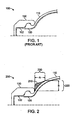
- FIG. 1 and FIG. 6 illustrate tire and rim system 100 including a clincher tire with sidewall portion 105 and rim 130.
- Tube 102 is shown in dashed lines for illustration for systems that include tubes (i.e., not tubeless).
- a clincher bicycle tire having sidewall portion 105 fits onto the rim 130 where the bead 120 of the tire engages (or hooks onto) the inside lip of the rim 130, then the tire is inflated either by inflating the inner-tube 102 or directly into the tire in a tubeless system in order to pressure seal the engagement between tire sidewall and rim 130.
- the tire sidewall portion 105 is designed to deform in shape in certain circumstances either from leaning a bicycle during maneuvering or cornering, the tire sidewall portion 105 can become deformed to a point where the likelihood of the tire separating from the rim 130 is increased.
- the unintended separation of the bead from the rim (area 610 separating from area 130, i.e., roll-off) is shown in FIG. 6 and FIG. 8 and is highly undesirable because of the sudden loss of traction and control.
- Tubular clincher tires claim to eliminate tire roll-off when properly installed, but one problem is that tubular tires (having the tube sewn directly into the tire) are difficult to repair if punctured and likely require replacement of the complete tire. Also, manufacturing tubular tires is more labor intensive and thus more costly.
- the present invention provides a bicycle tire including a first sidewall and a second sidewall each including an interior portion and an exterior portion.
- a rim attaching portion including a slipping reduction portion having an extended rim contact surface is connected to an inner circumference of each of the first sidewall and the second sidewall.
- a tire tread portion is connected to an outer circumference of the first sidewall and the second sidewall.
- a portion of the first sidewall and the second sidewall proximate to the inner circumference of the first sidewall and the second sidewall on the opposite side of the rim attaching portion from the slipping reduction portion has additional material providing a varying thickness.
- the present invention provides a bicycle tire and rim assembly including a rim and a tire.
- the tire comprises a first sidewall and a second sidewall each including an interior portion and an exterior portion, a rim attaching portion including means for reducing slipping coupled to an inner circumference of each of the first sidewall and the second sidewall; and cushioning means adjacent the rim attaching portion for preventing pinching a tube against the rim during compression.
- the present invention provides a bicycle tire and rim assembly including a rim and a tire.
- the tire comprising: a first sidewall and a second sidewall each including an interior portion and an exterior portion, a rim attaching portion including means for reducing slipping coupled to an inner circumference of each of the first sidewall and the second sidewall; and means adjacent the rim attaching portion for preventing the tire from rolling off the rim during lateral twisting forces between the rim and tire.
- the present invention provides a bicycle tire and rim assembly including a rim and a tire.
- the tire comprising: a first sidewall and a second sidewall each including an interior portion and an exterior portion, a rim attaching portion including means for reducing slipping coupled to an inner circumference of each of the first sidewall and the second sidewall; and means adjacent the rim attaching portion for preventing pinching a tube against the rim during compression and means for preventing the tire from rolling off the rim during lateral twisting forces between the rim and tire.
- a bicycle tire according to the invention may comprise a first sidewall and a second sidewall each including an interior portion and an exterior portion, a rim attaching portion including a slipping reduction portion having an extended rim contact surface coupled to an inner circumference of each of the first sidewall and the second sidewall. Further a tire tread portion coupled to an outer circumference of the first sidewall and the second sidewall is provided, wherein a portion of the first sidewall and the second sidewall proximate to said inner circumference of the first sidewall and the second sidewall on the opposite side of the rim attaching portion from said slipping reduction portion has additional material providing a varying thickness. In a preferred embodiment the varying thickness is provided on the exterior portion of the first sidewall and the second sidewall. It is also possible to provide the varying thickness on the interior portion of the first sidewall and the second sidewall.
- the varying thickness is provided on both the interior portion and the exterior portion of the first sidewall and the second sidewall.
- the varying thickness is preferably formed by a first additional material added to the exterior portion of the first sidewall and the second sidewall proximate to the inner circumference of the first sidewall and the second sidewall.
- the varying thickness may be formed by a second additional material added to the interior portion of the first sidewall and the second sidewall proximate to the inner circumference of the first sidewall and the second sidewall.
- the varying thickness is formed by a first additional material added to the exterior portion of the first sidewall and the second sidewall proximate to the inner circumference of the first sidewall and the second sidewall, and by a second additional material added to the interior portion of the first sidewall and the second sidewall proximate to the inner circumference of the first sidewall and the second sidewall.
- the second additional material may be configured to prevent pinching of an inner tube during compression to the tire.
- the first additional material is configured to prevent the tire from rolling off of a rim during compression of the tire.
- the slipping reduction portion is preferably configured to reduce an amount that the rim attaching portion slips on the rim during braking.
- the slipping reduction portion may be configured to press against an internal wall of the rim via air pressure.
- the second additional material is configured to prevent pinching of an inner tube during compression and lateral force to the tire
- the first additional material is configured to prevent the tire from rolling off of a rim during compression and lateral force to the tire
- the slipping reduction portion reduces the rim attaching portion from slipping on the rim during braking.
- the first additional material may be made of the same material as the sidewall.
- the first additional material can also be is made of different material than the sidewall.
- the second additional material may be made of different material than the sidewall.
- the slipping reduction material is made of the same material as the sidewall, but can also be made of different material than the sidewall.
- the first additional material has preferably a length on the exterior portion of the first sidewall and the second sidewall between 1.0mm and 23.0mm.
- the second additional material may preferably have a length on the interior portion of the first sidewall and the second sidewall between 1.0mm and 25.0mm.
- the slipping reduction material preferably has a length between 1.0mm and 20.0mm.
- the invention is also directed to a bicycle tire and rim assembly comprising a rim and a tire comprising a first sidewall and a second sidewall each including an interior portion and an exterior portion, a rim attaching portion including means for reducing slipping coupled to an inner circumference of each of the first sidewall and the second sidewall.
- the tire further comprises cushioning means adjacent the rim attaching portion for preventing pinching a tube against the rim during compression.
- the bicycle tire and rim assembly may further comprise a tire tread portion coupled to an outer circumference of the first sidewall and the second sidewall.
- the inner portion of the first sidewall and the second sidewall proximate to the inner circumference of the first sidewall and the second sidewall may have a varying thickness.
- Means for reducing slipping may be configured to reduce an amount that the rim attaching portion slips on the rim during braking.
- the bicycle tire and rim assembly may comprise a rim and a tire comprising a first sidewall and a second sidewall each including an interior portion and an exterior portion, a rim attaching portion including means for reducing slipping coupled to an inner circumference of each of the first sidewall and the second sidewall, and means adjacent the rim attaching portion for preventing the tire from rolling off the rim during lateral twisting forces between the rim and tire.
- the exterior portion of the first sidewall and the second sidewall proximate to the inner circumference of the first sidewall and the second sidewall may have a varying thickness.
- the means for reducing slipping is preferably configured to reduce an amount that the rim attaching portion slips on the rim during braking.
- a bicycle tire and rim assembly according to the invention may further comprise a rim, and a tire comprising a first sidewall and a second sidewall each including an interior portion and an exterior portion, a rim attaching portion including means for reducing slipping coupled to an inner circumference of each of the first sidewall and the second sidewall, and means adjacent the rim attaching portion for preventing pinching a tube against the rim during compression and means for preventing the tire from rolling off the rim during lateral twisting forces between the rim and tire.
- the interior portion and the exterior portion of the first sidewall and the second sidewall proximate to the inner circumference of the first sidewall and the second sidewall preferably each has a varying thickness, and the means for reducing slipping is configured to reduce an amount that the rim attaching portion slips on the rim during braking.
- FIG. 2 illustrates a system 200 including a tire including sidewall portion 110 attached to a rim 130 according to an embodiment of the invention.
- the tire is formed with an additional material 210 formed in the sidewall of the tire.
- Additional material 210 may comprise a separate material from the tire material bonded or integrated thereto, or may be additional material of the same type.
- the additional material 210 is only added to the portion of the tire that is near the inner circumference portion of the exterior of the sidewall before the bead portion 120 (i.e., rim coupling portion).
- the additional material 210 varies in thickness from its beginning to end in a "hump" or "hill” shape.
- the amount of additional material 210 can be determined based on a volumetric equation determined by length, width, and height (i.e., thickness) dimensions throughout the additional material.
- the additional material 210 allows the tire to compress normally during use (e.g., with a bicycle, a motorized bicycle, carts, etc.), but beyond a particular threshold or range of compression, the additional material 210 performs as a "bumper" to control further compression of the tire. It should be noted that with additional weight, such as from a motor driven bicycle (see, e.g., FIG. 11A-B ), compression of the tire occurs easier than with lighter loads, for example a typical non-motorized bicycle with a rider having an average weight.
- the additional material 210 on the tire adjacent to the edge of the rim 130 minimizes further compression, as well as alters the path of tire compression to prevent an inner-tube 102 from being pinched by the rim edges and the object causing the tire compression.
- the additional material 210 incorporated onto the exterior of the sidewall of the tire sets a limit that the tire is able to deform under riding conditions that cause additional twisting of the tire relative to the rim due to torque or other twisting forces between the tire and rim, and asymmetric tire compression, such as cornering with additional weight, striking a sharp object, running over a pot hole, etc.
- the additional material 210 acts as structural reinforcement on the sidewall of the tire close to the edge of the rim 130, which allows tire deformity as intended and only becomes active when tire deformity reaches the threshold, in which case the reinforcement restricts further tire deformity to prevent roll-off.
- the additional material 210 is only incorporated at the inner circumference of the external tire sidewall before the bead portion and next to the rim 130 edge. Therefore, the embodiments of the invention reduce overall tire weight in comparison to adding additional thickness to the whole exterior tire sidewall or complete tire.
- the embodiments of the invention still allow for similar level of tire compression to the sidewall portion 110 as a typical tire tread, such as tire sidewall portion 105, for better tire traction and are less expensive to produce as compared to reinforcing the entire sidewall of the tire.
- Table I provides ranges of length for distance A 230 and distance B 220 for the additional material 210 for different tire sizes. It should be noted that other embodiments of the invention may have different maximum and preferred ranges of length based on the application and desired compression threshold. It should also be noted that the thickness of the additional material 210 may be adjusted for different compression thresholds. Table I A B Tire Size Maximum Preferred Maximum Preferred 20" 23.0mm 1.0-10.0mm 10.0mm 1.0-6.0mm 24" 24.0mm 1.0-10.0mm 13.0mm 1.0-6.0mm 26" 24.0mm 1.0-10.0mm 13.0mm 1.0-6.0mm 700C 18.0mm 1.0-10.0mm 10.0mm 1.0-6.0mm
- the additional material 210 is incorporated into the tire sidewall, time, effort and money can be saved due to not having to purchase and install a liner to the inside of the tire.
- the embodiments of the invention provide pinch flat protection without having to replace their entire wheel.
- the tire including the additional material 210 is compatible with conventional clincher rims and, therefore, does not require any additional expense of changing rims.
- the embodiments of the invention allow for tire repair using conventional clincher tire repair techniques as the tire with additional material 210 is applicable to conventional clincher rims and does not require the added expense of purchasing and replacing the clincher type rim with a tubeless specific rim.
- the tire and additional material may be made out of various compounds of rubber, rubber compounds mixed with additional materials, such as Kevlar® chips, nylon chips, cotton-chips, various fibers, etc. It should be noted that conventional manufacturing techniques may be used to form, mold, extrude, etc. the tire including the additional material 210.
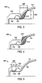
- FIG. 3 illustrates a system 300 including a tire attached to a rim 130 according to another embodiment of the invention.
- the sidewall of the tire is formed with an additional material 310 formed in the interior sidewall of the tire.
- the additional material 310 is only added to the portion of the sidewall of the tire that is near the inner circumference of the interior side of the sidewall before the bead portion 120.
- the additional material 310 varies in thickness from its beginning to end in a "hump" or "hill” shape, with an outer perimeter having a serpentine shape.
- the amount of additional material 310 can be determined based on a volumetric equation determined by length, width, and height (i.e., thickness) dimensions throughout the additional material.
- the additional material 310 allow the tire to compress normally during use (e.g., with a bicycle, a motorized bicycle, carts, etc.), but beyond a particular threshold or range of compression and lateral force, the additional material 310 performs as a "bumper" to control further compression of the tire. It should be noted that with additional weight, such as from a motor driven bicycle, compression of the tire occurs easier than with lighter loads, for example a typical non-motorized bicycle with a rider having an average weight.
- the additional material 310 on the tire adjacent to the edge of the rim 130 on the interior of the sidewall before the bead portion 120 minimizes further compression, as well as alters the path of tire compression to prevent an inner-tube 102 from being pinched ("pinching") by the rim edges and the object causing the tire compression.
- the additional material 310 incorporated onto the internal sidewall of the tire sets a limit that the tire is able to deform under riding conditions that cause additional compression and lateral force, such as cornering with additional weight, striking a sharp object, running over a pot hole, etc.
- the additional material 310 acts as structural reinforcement on the sidewall of the tire close to the edge of the rim 130, which allows tire deformity as intended and only becomes active when tire deformity reaches the threshold, in which case the reinforcement restricts further tire deformity to prevent pinching.
- the additional material 310 is only incorporated at the inner circumference of the side wall portion of the internal tire sidewall before the bead portion 120 and next to the rim 130 edge. Therefore, the embodiments of the invention reduce overall tire weight in comparison to adding additional thickness to the whole outer tire sidewall or complete tire.
- the embodiments of the invention still allow for similar level of tire compression as a typical tire tread portion, such as tire sidewall portion 105, for better tire traction and are less expensive to produce as compared to reinforcing the entire sidewall of the tire.
- Table II provides ranges of length for distance C 330 and distance D 320 for the additional material 310 for different tire sizes. It should be noted that other embodiments of the invention may have different maximum and preferred ranges of length based on the application and desired compression threshold. It should also be noted that the thickness of the additional material 310 may be adjusted for different compression thresholds. Table II C D Tire Size Maximum Preferred Maximum Preferred 20" 25.0mm 1.0-12.0mm 14.0mm 1.0-8.0mm 24" 26.0mm 1.0-12.0mm 17.0mm 1.0-8.0mm 26" 26.0mm 1.0-12.0mm 17.0mm 1.0-8.0mm 700C 20.0mm 1.0-12.0mm 14.0mm 1.0-8.0mm
- the additional material 310 is incorporated into the tire, time, effort and money can be saved due to not having to purchase and install a liner to the inside of the tire.
- the embodiments of the invention provide pinch flat protection without having to replace their entire wheel.
- the tire including the additional material 310 is compatible with conventional clincher rims and, therefore, does not require any additional expense of changing rims.
- the embodiments of the invention allow for tire repair using conventional clincher tire repair techniques as the tire with additional material 310 is applicable to conventional clincher rims and does not require the added expense of purchasing and replacing the clincher type rim with a tubeless specific rim.
- the tire and additional material 310 may be made out of various compounds of rubber, rubber compounds mixed with additional materials, such as Kevlar® chips, nylon chips, cotton-chips, various fibers, etc. It should be noted that conventional manufacturing techniques may be used to form, mold, extrude, etc. the tire including the additional material 310.
- FIG. 4 illustrates system 400 including a tire with a sidewall portion 110, additional material 210 and additional material 310 according to one embodiment of the invention.
- the additional material 210 and the additional material 310 both operate together to set a limit that the tire is able to deform under riding conditions that cause additional compression and lateral force, such as cornering with additional weight, striking a sharp object, running over a pot hole, etc.
- the additional material 210 and additional material 310 act in tandem as structural reinforcement on the sidewall of the tire close to the edge of the rim 130, which allows tire deformity as intended and only becomes active when tire deformity reaches the threshold, in which case the reinforcement restricts further tire deformity to prevent roll-off via additional material 210 and pinching via additional material 210 and/or 310.
- FIG. 5 illustrates a system 500 including a tire with sidewall portion 110 attached to a rim 130 according to another embodiment of the invention.
- the tire is formed with an additional material 510 in the tire.
- the additional material 510 is only added to the portion of the tire at the end of bead 520.
- the additional material 510 extending from the bead of the tire when mounted onto the rim 130, rests against the inner sidewall of the rim 130, directly below the engagement of the rim and bead of the tire.
- the air pressure pushes the extended material into the sidewall of the rim 130, which increases surface contact and friction force between the tire and the rim 130 and minimizes tire slipping.
- the air pressure may be supplied by a tire with a tube or a tubeless tire as well.
- the additional material 510 has a portion that has a continuous shape and another portion that varies in shape, so that the additional material 510 may have a "duck bill" shape.
- the amount of additional material 510 can be determined based on a volumetric equation determined by length, width, and height (i.e., thickness) dimensions throughout the additional material.
- the additional material 510 is only incorporated at the end of bead portion 520 and next to the inner sidewall of the rim 130. Therefore, the embodiments of the invention reduce overall tire weight in comparison to adding additional thickness to the whole outer tire sidewall or complete tire.
- Table III provides ranges of length for distance E 330 for the additional material 510 for different tire sizes. It should be noted that other embodiments of the invention may have different maximum and preferred ranges of length based on the application and desired slipping force threshold. It should also be noted that the thickness of the additional material 510 may be adjusted for different compression thresholds. Table III E Tire Size Maximum Preferred 20" 20.0mm 1.0-10.0mm 24" 20.0mm 1.0-10.0mm 26" 20.0mm 1.0-10.0mm 700C 20.0mm 1.0-10.0mm
- the tire including the additional material 510 is compatible with conventional clincher rims and, therefore, does not require any additional expense of changing rims.
- the embodiments of the invention allow for tire repair using conventional clincher tire repair techniques as the tire with additional material 510 is applicable to conventional clincher rims and does not require the added expense of purchasing and replacing the clincher type rim with a tubeless specific rim.
- the tire and additional material 510 may be made out of various compounds of rubber, rubber compounds mixed with additional materials, such as Kevlar® chips, nylon chips, cotton-chips, various fibers, etc. It should be noted that conventional manufacturing techniques may be used to form, mold, extrude, etc. the tire including the additional material 510.
- Some embodiments may incorporate any combination of embodiments from FIGS. 2 , 3, 4 and 5 . That is, additional material 210, additional material 310, and additional material 510 can be included in embodiments of the invention in any combination.
- FIG. 6 illustrates a conventional tire having a sidewall 105 attached to a rim 130.
- the tire tread portion 609 is being compressed (e.g., from additional weight of a motor, rider, etc.) and undergoing lateral force from friction as the tire is angled (as in a turn) against a ground surface.
- the tire has its bead 610 separating from the rim 130 (i.e., rolling off) as the tire only has a standard homogeneous sidewall 630 that is deforming from the compression force.
- FIG. 7 illustrates tire attached to a rim 130 according to the embodiments of the invention.
- the tire tread portion 709 is being compressed (e.g., from additional weight of a motor, rider, etc.) and undergoing lateral force from friction as the tire is angled (as in a turn) against a ground surface.
- the tire has its bead 120 remaining in contact with the rim 130 as the tire has a sidewall 110 and 720 that has additional support from additional material 210 that prevents deforming of the tire from the compression force.
- FIG. 8 illustrates a typical tire attached to a rim where the tire wall is separating from the rim due to compression and lateral force (i.e., roll-off) as in FIG. 6 .
- FIG. 9 illustrates a tire according to an embodiment of the invention going through the same compression as with the tire in FIG 8 . Due to the incorporation of the additional material (e.g., additional material 210, additional material 310, additional material 510, or any combination), the tire remains on the rim during the same compression and lateral force that would cause the tire to separate from the rim as shown in FIGS. 6 and 8 .
- additional material e.g., additional material 210, additional material 310, additional material 510, or any combination
- FIG. 10 illustrates an embodiment 1000 including a combination of the embodiments illustrated in FIGS. 2 , 3 and 5 that prevents roll-off, pinching as well as slipping, as previously described.
- FIG. 11A illustrates an example bicycle 1100 including system 200 illustrated in FIG. 2 and FIG.11B .
- the bicycle 1100 includes a motor 1110 (e.g., an electric motor, a gas motor, a gas/electric motor, etc.) that adds additional weight to the bicycle.
- a motor 1110 e.g., an electric motor, a gas motor, a gas/electric motor, etc.
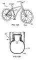
- FIG. 12A illustrates an example bicycle 1100 including system 300 illustrated in FIG. 3 and FIG. 12B .
- the bicycle 1100 includes a motor 1110 (e.g., an electric motor, a gas motor, a gas/electric motor, etc.) that adds additional weight to the bicycle.
- a motor 1110 e.g., an electric motor, a gas motor, a gas/electric motor, etc.
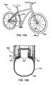
- FIG. 13A illustrates an example bicycle 1100 including system 400 illustrated in FIG. 4 and FIG. 13B .
- the bicycle 1100 includes a motor 1110 (e.g., an electric motor, a gas motor, a gas/electric motor, etc.) that adds additional weight to the bicycle.
- a motor 1110 e.g., an electric motor, a gas motor, a gas/electric motor, etc.
- FIG. 14A illustrates an example bicycle 1100 including system 500 illustrated in FIG. 5 and FIG. 14B .
- the bicycle 1100 includes a motor 1110 (e.g., an electric motor, a gas motor, a gas/electric motor, etc.) that adds additional weight to the bicycle.
- a motor 1110 e.g., an electric motor, a gas motor, a gas/electric motor, etc.
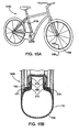
- FIG. 15A illustrates an example bicycle 1100 including system 1000 illustrated in FIG. 10 and FIG. 15B .
- the bicycle 1100 includes a motor 1110 (e.g., an electric motor, a gas motor, a gas/electric motor, etc.) that adds additional weight to the bicycle.
- a motor 1110 e.g., an electric motor, a gas motor, a gas/electric motor, etc.
Landscapes
- Engineering & Computer Science (AREA)
- Mechanical Engineering (AREA)
- Tires In General (AREA)
Applications Claiming Priority (4)
| Application Number | Priority Date | Filing Date | Title |
|---|---|---|---|
| US15927909P | 2009-03-11 | 2009-03-11 | |
| US12/464,780 US20100230028A1 (en) | 2009-03-11 | 2009-05-12 | Bicycle tire |
| US12/464,813 US20100230029A1 (en) | 2009-03-11 | 2009-05-12 | Bicycle tire |
| US12/464,796 US20100230025A1 (en) | 2009-03-11 | 2009-05-12 | Bicycle tire |
Publications (2)
| Publication Number | Publication Date |
|---|---|
| EP2228237A2 true EP2228237A2 (de) | 2010-09-15 |
| EP2228237A3 EP2228237A3 (de) | 2010-09-22 |
Family
ID=42237423
Family Applications (1)
| Application Number | Title | Priority Date | Filing Date |
|---|---|---|---|
| EP09015683A Withdrawn EP2228237A3 (de) | 2009-03-11 | 2009-12-18 | Fahrradreifen |
Country Status (1)
| Country | Link |
|---|---|
| EP (1) | EP2228237A3 (de) |
Cited By (3)
| Publication number | Priority date | Publication date | Assignee | Title |
|---|---|---|---|---|
| CN108688407A (zh) * | 2017-03-30 | 2018-10-23 | 正新橡胶工业股份有限公司 | 无内胎的自行车轮胎结构 |
| DE202018005308U1 (de) * | 2018-11-16 | 2020-02-18 | Rti Sports Gmbh | Reifenschutzelement |
| DE102022121909A1 (de) * | 2022-08-30 | 2024-02-29 | Shimano Inc. | Felge für ein vom menschen angetriebenes fahrzeug |
Family Cites Families (7)
| Publication number | Priority date | Publication date | Assignee | Title |
|---|---|---|---|---|
| DE2305535C2 (de) * | 1973-02-05 | 1983-12-01 | Continental Gummi-Werke Ag, 3000 Hannover | Fahrzeugrad |
| DE2526758A1 (de) * | 1975-06-14 | 1976-12-30 | Hans Wimmer | Fahrzeugluftreifen mit notlaufvorrichtung vorzugsweise fuer tiefbett-felgen |
| GB2104459B (en) * | 1981-07-30 | 1985-04-11 | Simon Peter Pointer | Tyres for wheels |
| JPS6012315A (ja) * | 1983-06-30 | 1985-01-22 | Yamaha Motor Co Ltd | ワイヤスポ−ク車輪 |
| JPH01145208A (ja) * | 1987-11-30 | 1989-06-07 | Sumitomo Rubber Ind Ltd | Atv用ランフラットタイヤとリムの組立体 |
| IT1227628B (it) * | 1987-11-30 | 1991-04-23 | Sumitomo Rubber Ind | Pneumatico. |
| GB8813776D0 (en) * | 1988-06-10 | 1988-07-13 | Sumitomo Rubber Ind | Motor cycle radial tyre |
-
2009
- 2009-12-18 EP EP09015683A patent/EP2228237A3/de not_active Withdrawn
Non-Patent Citations (1)
| Title |
|---|
| None |
Cited By (3)
| Publication number | Priority date | Publication date | Assignee | Title |
|---|---|---|---|---|
| CN108688407A (zh) * | 2017-03-30 | 2018-10-23 | 正新橡胶工业股份有限公司 | 无内胎的自行车轮胎结构 |
| DE202018005308U1 (de) * | 2018-11-16 | 2020-02-18 | Rti Sports Gmbh | Reifenschutzelement |
| DE102022121909A1 (de) * | 2022-08-30 | 2024-02-29 | Shimano Inc. | Felge für ein vom menschen angetriebenes fahrzeug |
Also Published As
| Publication number | Publication date |
|---|---|
| EP2228237A3 (de) | 2010-09-22 |
Similar Documents
| Publication | Publication Date | Title |
|---|---|---|
| US20100230029A1 (en) | Bicycle tire | |
| EP2465710B1 (de) | Radialluftreifen | |
| US9925828B2 (en) | Bicycle wheel rim | |
| US11772418B2 (en) | Wheel | |
| EP3386772B1 (de) | Felgenleiste für fahrradfelge | |
| EP2228237A2 (de) | Fahrradreifen | |
| EP0820884A3 (de) | Luftreifen | |
| US10137729B2 (en) | Reinforced bicycle rim | |
| JP3377448B2 (ja) | ランフラットタイヤ | |
| CN203401883U (zh) | 一种具有胎圈结构改进的轮胎 | |
| CA2950932C (en) | Foam tire flap for low pressure applications | |
| EP3594026B1 (de) | Reifenstruktur und befestigungsstruktur dafür | |
| EP3578388B1 (de) | Felgenband für fahrradfelge | |
| FR2469297A2 (fr) | Pneumatique de securite | |
| CN101623988A (zh) | 车辆用充气轮胎 | |
| CN110962509A (zh) | 一种缺气保用轮胎 | |
| US10596850B2 (en) | Rim strip for bicycle rim | |
| KR101301100B1 (ko) | 차량용 공기입 타이어 | |
| CN110605941A (zh) | 充气轮胎的胎唇加强装置 | |
| KR20110072659A (ko) | 벨트 에지를 보강하여서 된 자동차용 타이어 | |
| CN110001306A (zh) | 充气子午线轮胎 | |
| KR101628070B1 (ko) | 분리된 사이드월을 가지는 공기입 타이어 | |
| CN203401884U (zh) | 一种具有胎圈结构改进的轮胎 | |
| CN109130712A (zh) | 跑气保护轮圈总成 | |
| CN106274303A (zh) | 跑气保护轮圈总成 |
Legal Events
| Date | Code | Title | Description |
|---|---|---|---|
| PUAI | Public reference made under article 153(3) epc to a published international application that has entered the european phase |
Free format text: ORIGINAL CODE: 0009012 |
|
| PUAL | Search report despatched |
Free format text: ORIGINAL CODE: 0009013 |
|
| AK | Designated contracting states |
Kind code of ref document: A2 Designated state(s): AT BE BG CH CY CZ DE DK EE ES FI FR GB GR HR HU IE IS IT LI LT LU LV MC MK MT NL NO PL PT RO SE SI SK SM TR |
|
| AX | Request for extension of the european patent |
Extension state: AL BA RS |
|
| AK | Designated contracting states |
Kind code of ref document: A3 Designated state(s): AT BE BG CH CY CZ DE DK EE ES FI FR GB GR HR HU IE IS IT LI LT LU LV MC MK MT NL NO PL PT RO SE SI SK SM TR |
|
| AX | Request for extension of the european patent |
Extension state: AL BA RS |
|
| 17P | Request for examination filed |
Effective date: 20110322 |
|
| 17Q | First examination report despatched |
Effective date: 20130108 |
|
| STAA | Information on the status of an ep patent application or granted ep patent |
Free format text: STATUS: THE APPLICATION IS DEEMED TO BE WITHDRAWN |
|
| 18D | Application deemed to be withdrawn |
Effective date: 20130522 |