EP2228191A2 - Dichtelement zur Abdichtung elektrischer Kontaktelemente beim Spritzgießen - Google Patents
Dichtelement zur Abdichtung elektrischer Kontaktelemente beim Spritzgießen Download PDFInfo
- Publication number
- EP2228191A2 EP2228191A2 EP10001830A EP10001830A EP2228191A2 EP 2228191 A2 EP2228191 A2 EP 2228191A2 EP 10001830 A EP10001830 A EP 10001830A EP 10001830 A EP10001830 A EP 10001830A EP 2228191 A2 EP2228191 A2 EP 2228191A2
- Authority
- EP
- European Patent Office
- Prior art keywords
- sealing element
- contact
- cavity
- sealing
- contact element
- Prior art date
- Legal status (The legal status is an assumption and is not a legal conclusion. Google has not performed a legal analysis and makes no representation as to the accuracy of the status listed.)
- Granted
Links
Images
Classifications
-
- B—PERFORMING OPERATIONS; TRANSPORTING
- B29—WORKING OF PLASTICS; WORKING OF SUBSTANCES IN A PLASTIC STATE IN GENERAL
- B29C—SHAPING OR JOINING OF PLASTICS; SHAPING OF MATERIAL IN A PLASTIC STATE, NOT OTHERWISE PROVIDED FOR; AFTER-TREATMENT OF THE SHAPED PRODUCTS, e.g. REPAIRING
- B29C45/00—Injection moulding, i.e. forcing the required volume of moulding material through a nozzle into a closed mould; Apparatus therefor
- B29C45/14—Injection moulding, i.e. forcing the required volume of moulding material through a nozzle into a closed mould; Apparatus therefor incorporating preformed parts or layers, e.g. injection moulding around inserts or for coating articles
- B29C45/14639—Injection moulding, i.e. forcing the required volume of moulding material through a nozzle into a closed mould; Apparatus therefor incorporating preformed parts or layers, e.g. injection moulding around inserts or for coating articles for obtaining an insulating effect, e.g. for electrical components
-
- B—PERFORMING OPERATIONS; TRANSPORTING
- B29—WORKING OF PLASTICS; WORKING OF SUBSTANCES IN A PLASTIC STATE IN GENERAL
- B29C—SHAPING OR JOINING OF PLASTICS; SHAPING OF MATERIAL IN A PLASTIC STATE, NOT OTHERWISE PROVIDED FOR; AFTER-TREATMENT OF THE SHAPED PRODUCTS, e.g. REPAIRING
- B29C45/00—Injection moulding, i.e. forcing the required volume of moulding material through a nozzle into a closed mould; Apparatus therefor
- B29C45/14—Injection moulding, i.e. forcing the required volume of moulding material through a nozzle into a closed mould; Apparatus therefor incorporating preformed parts or layers, e.g. injection moulding around inserts or for coating articles
- B29C45/14336—Coating a portion of the article, e.g. the edge of the article
- B29C45/14418—Sealing means between mould and article
-
- B—PERFORMING OPERATIONS; TRANSPORTING
- B29—WORKING OF PLASTICS; WORKING OF SUBSTANCES IN A PLASTIC STATE IN GENERAL
- B29C—SHAPING OR JOINING OF PLASTICS; SHAPING OF MATERIAL IN A PLASTIC STATE, NOT OTHERWISE PROVIDED FOR; AFTER-TREATMENT OF THE SHAPED PRODUCTS, e.g. REPAIRING
- B29C45/00—Injection moulding, i.e. forcing the required volume of moulding material through a nozzle into a closed mould; Apparatus therefor
- B29C45/17—Component parts, details or accessories; Auxiliary operations
- B29C45/26—Moulds
- B29C45/2608—Mould seals
-
- B—PERFORMING OPERATIONS; TRANSPORTING
- B29—WORKING OF PLASTICS; WORKING OF SUBSTANCES IN A PLASTIC STATE IN GENERAL
- B29C—SHAPING OR JOINING OF PLASTICS; SHAPING OF MATERIAL IN A PLASTIC STATE, NOT OTHERWISE PROVIDED FOR; AFTER-TREATMENT OF THE SHAPED PRODUCTS, e.g. REPAIRING
- B29C45/00—Injection moulding, i.e. forcing the required volume of moulding material through a nozzle into a closed mould; Apparatus therefor
- B29C45/14—Injection moulding, i.e. forcing the required volume of moulding material through a nozzle into a closed mould; Apparatus therefor incorporating preformed parts or layers, e.g. injection moulding around inserts or for coating articles
- B29C2045/1486—Details, accessories and auxiliary operations
- B29C2045/14934—Preventing penetration of injected material between insert and adjacent mould wall
Definitions
- the present invention relates to a sealing element for an injection molding machine for sealing at least one electrical contact element of a plug contact during partial encapsulation with a plastic molding compound, an injection molding machine for producing the contact element comprehensive plug contact of a plastic molding and a method for producing the plug contact of the plastic molding.
- plastic moldings with electrical plug contacts which represent an electrical interface to other electrical components.
- an electrical component integrated in a housing always requires an electrical connection in the case of operation on a voltage network.
- This can advantageously be provided directly on the housing as integral with this trained connector.
- electrical connecting conductors are embedded, which protrude on both sides of the housing, wherein a first free end of the connecting conductor forms a contact element of the plug and the second free end protrudes into the interior of the housing, where it is for the electrical component either also via a connector or directly by soldering can be contacted.
- electrical components such as stators of electric motors for pump applications completely with a plastic
- Such components also have electrical plug-in contacts in order to be connected and energized with another electrical component, for example a control unit or a frequency converter.
- metallic conductors are used, for example, stamped grid or individual formed in cross section as a round or rectangular profile connecting conductors which are embedded in the plastic extrusion and protrude only at a free end in the region of the plug contact from the plastic molding with a Maisier Scheme.
- the other end of the connection conductor is connected directly or indirectly to the electrical component.
- the metallic connecting conductors are first inserted into an injection mold and then partially encapsulated, which results in a plastic-metal composite construction, which can be formed arbitrarily complex according to the cavity to be filled with the plastic molding material of the tool.
- a connecting conductor referred to below as the contact element
- this end must protrude from the cavity or project into an area into which the molding compound can not flow.
- thermoplastic insert Another disadvantage is in the execution of the Insert made of metal that the likewise metallic connecting conductors could be damaged or bent during insertion into the opening.
- a thermoplastic insert also has the disadvantage that it could deform under the temperature and the pressure of the injected molding compound and thus can not be used as often as desired.
- a sealing element for an injection molding machine for sealing at least one electrical contact element of a plug contact during partial encapsulation with a plastic molding composition is proposed, which is formed of a flexible material and has at least one slot into which the contact element is positively inserted such that it is circumferentially of the Sealing element is completely enclosed, wherein the sealing element elastically deformed under the action of a compressive force, that it applies sealingly against the contact element.
- Such a sealing element can be introduced into an injection molding machine and completely seal off the contacting region of the at least one electrical contact element, so that no plastic molding compound flows past the contact element during injection molding.
- the sealing element is made of a flexible material which elastically deforms upon exertion of a compressive force on the sealing element.
- the inner wall of the at least one slot is by the deformation on all sides against the Maisier Anlagen of Pressed contact element and thus seals the entire circumference of the contact element, in particular to the cavity of the injection mold down from. There are no free spaces between the sealing element and the contact element, in which any plastic molding compound can enter and form a degree after cooling.
- a flexible sealing element is that the surface of the contact element, which may be specially designed to achieve better electrical conductivity, for example gold-plated or galvanized and thus sensitive, is not damaged.
- the sealing element is in one piece and can remain in the injection molding machine after the injection molding process. The sealing element does not form part of the plug-in contact to be produced.
- the contact element may be made of any electrically conductive material, composite material, in particular of a metal, a metal alloy or a metal-coated material.
- a metal for use in a plug-in contact, it has a longitudinal shape, which may be round or rectangular in cross-section.
- Such a contact element may thus be formed as a round pin or tab, i. have a pin or tongue-shaped contact area, which must be sealed during the injection molding.
- the sealing element may be adapted to the shape of the contact element.
- the slot is then formed by two opposing lips which bear against the two wide contact surfaces of the contact element. Since the lips already abut each other in such a slot in the relaxed state of the sealing element, the sealing element brings the contact element during insertion a certain counter-force, since the contact element must displace rubber-elastic material of the sealing element in the amount of its volume. The restoring force already causes a first sealing action between the contact element and the sealing element.
- the at least one slot may therefore be provided according to the invention to form the at least one slot as a recess.
- the cross section of the recess is adapted to the cross section of the electrical contact element, in particular for forming a positive reception of the contact element in the sealing element, so that the contact element fully rests in the assembled state on the inside of the recess.
- the positive connection or frictional engagement of a contact element introduced into the slot has the advantage that the contact element is held in the sealing element and no additional holding means is necessary in order to hold the contact element in relation to the cavity in position.
- the recess may have a slightly larger dimension in its cross-section than the outer dimension of the contact element.
- This has the advantage that the contact element can be introduced without effort in the sealing element. Although this results in a small clearance between the inner wall of the recess and the contact element, for example, in the amount of a few tenths of a millimeter, however, the sealing element can deform sufficiently elastic upon selection of a sufficiently elastic material and under the action of a compressive force, so that it sealingly against the contact element creates and closes the open spaces.
- the initially resulting free space has the additional advantage that when sealing a plurality of contact elements arranged in a row, tolerances in their distances can be compensated.
- the sealing element may preferably be formed from an elastomer, in particular a silicone.
- the elastomer is a rubbery material, which has excellent Abdich für by its elastic deformation when pressure is applied. It may be formed soft, which leads to a particularly high sealing effect, but also be designed to be hard, so that the wear of the sealing element as a result of sharp-edged contact elements is low.
- a preferred choice of material is a moderately soft, or hard elastomer, which combines both advantages compromise.
- a silicone has the advantage that it does not adhere to the casting material due to its smooth surface, which comes into contact with the insertion side of the sealing element. This makes it possible - as part of the mechanical wear by sharp edges of the contact element - reuse the sealing element as often as desired, so that it can remain permanently in the injection molding machine.
- the sealing element may be formed substantially parallelepiped in cross-section. It thus forms a component which can be used particularly easily in an injection molding machine, in particular in a cavity provided for the sealing element.
- the recess and / or the recess may extend in the insertion direction of the contact element along the entire thickness of the sealing element.
- such a sealing element can be made simpler than a sealing element in which the slot extends only partially in the direction of the thickness.
- the sealing element can be pushed onto the contact element from both end faces, which have the slot opening, as far as no preferred orientation is necessary. This simplifies the handling and makes it possible to continue to use the sealing element when the first end face is worn as a result of intensive use.
- Another advantage of a continuous slot is that the sealing element exerts no axial forces on the contact element and the contact element is thus not pushed out of the sealing element again. When pressure is applied to the end face of the sealing element, only a force acting radially on it is applied to the contact element.
- the sealing element In the insertion direction, the sealing element should have a thickness which is greater than the axial length of the contacting region of the contact element. This ensures that upon exertion of a compressive force on the insertion end facing away from the end face of the sealing element and the associated displacement of sealing material no damage to the contact element takes place.
- the sealing element may preferably have a thickness between 8 and 20 millimeters.
- the sealing element can have a width between 8 and 12 millimeters perpendicular to the insertion direction. In combination with a thickness between 8 and 20 millimeters, this ensures that sufficient sealing material is present so that the sealing element can apply sufficient restoring force.
- the preferably substantially parallelepiped-shaped sealing element can furthermore preferably have at least one side edge which is parallel to the insertion direction and which is shaped differently in relation to the other side edges. This defines a preferred direction according to which the sealing element is to be inserted into the injection molding machine. For example, one or three of the side edges may be rounded, whereas the other or the other side edges form a solid right angle.
- the sealing element can be provided to seal a plurality of electrical contact elements during the injection molding process.
- it may have several slots, i. Have incisions and / or recesses, which are aligned parallel to each other.
- an injection molding machine for the production of plastic moldings with at least one of a plastic molding compound to be encapsulated electrical contact element of a plug contact proposed, with an insert of a first tool part having a cavity into which the flexible sealing element according to the invention with at least one slot can be used the insert has a wall separating the cavity from a cavity into which the plastic compound is injectable, the wall having at least one opening for passing the electrical contact aligned with the slot of the sealing element, and a pressure piece fixed in the inserted state of the sealing element is applied to this, wherein the injection mold at least during the Spritzg screens dressess exerts a compressive force on the pressure piece.
- the pressure force is transmitted to the sealing element.
- the pressure piece may be a pressure plate, which may abut against the end face of the sealing element facing away from the cavity. In this way, a uniform force is exerted on the sealing element, so that a uniform contact of the sealing element is achieved at the periphery of the contact element.
- the pressure force can preferably be exerted on the end face of the sealing element facing away from the cavity, so that the sealing element is pressed onto the dividing wall.
- the sealing element is deformed in such a way that in the case of an incision as a slot, the lips are pressed against each other and in the case of a recess, the inner walls of the recess bulge inwardly into the recess. In this way, a contact element introduced into the slot is fixed and sealed.
- the pressure exerted on the contact element acts perpendicular to the insertion direction.
- the compressive force may be provided by the closing movement of the injection molding tool, i. the merging of the first and a second cavity forming tool part are automatically applied by suitable means.
- a fixation and a seal of the contact element takes place in good time before the injection molding process.
- the pressure force can be achieved with the opening of the injection mold, i. the moving apart of the first and the second tool part, let down, so that relaxes the sealing element and releases the contact element for removal.
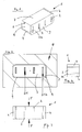
- FIG. 1 shows the sealing element 1 according to the invention for an injection molding machine 10 for sealing at least one not shown electrical contact element 21, 21a of a plug contact during partial encapsulation with an easy-flowing, in particular a duroplastic plastic molding compound in perspective view.
- the sealing element 1 is made of a Gusssililkon that is temperature resistant and ensures high resilience and thus a good sealing effect even at high temperatures. It can be adapted to the respective requirements by various hardnesses, for example 55 Shore or 80 Shore.
- the sealing element 1 has four slots in the form of elongate recesses 2, 2 a, into which four corresponding contact elements 21, 21 a can be inserted.
- the contact elements 21, 21a are executed in this embodiment in the form of contact tongues which are enclosed by the sealing element 1.
- other profiles can be used, for example, pins round or square cross-section, in which case the recesses 2, 2a of the sealing element 1 are adapted to this shape in order to achieve an optimum sealing effect.
- This part enclosed by the sealing element represents the electrical contact area for the plug contact of the plastic molded part to be produced.
- the sealing element 1 is substantially cuboid. It has three rounded side edges 4 and a side edge 5, at which the left lateral side surface 6 and the upper longitudinal side surface 7 abut one another at right angles. As a result, the sealing element 1 is given a preferred direction for insertion into the injection molding machine 10.
- FIG. 2 shows a view of the sealing element 1 in the inserted state in the injection molding machine 10 with a view of the front side 3.
- contact elements 21, 21a are inserted into the sealing element 1 positively and are circumferentially completely surrounded by the sealing element 1.
- the protruding from the sealing element 1 end portions of the contact elements 21, 21a protrude into the cavity and are encapsulated there by the plastic molding compound.
- the contact elements 21, 21a thus form metallic inserts.
- From the injection molding machine 10 is only an insert 8 of a first tool part shown in cross-section, which has a hollow receiving space, in which the sealing element 1 is inserted at a small distance 9 to the cavity inner wall.
- the receiving space can also be adapted to the dimensions of the sealing element 1, so that the sealing element rests positively in the receiving space.
- the inner surfaces of the receiving space then form upon insertion of the sealing element 1 in the receiving space sliding surfaces.
- the sealing element 1 is held by the contact elements 21, 21a.
- a contact element 21a is shown, which is wider than the other contact elements 21. This asymmetry in the contact element arrangement causes a certain orientation of the sealing element 1 during insertion of the contact elements 21, 21a in the slots 2, 2a. The correct orientation is determined by the position of the non-rounded side edge 5.
- FIG. 3 shows a view of the upper longitudinal side surface 7 of the sealing element 1.
- the dashed lines indicate the recesses 2 in the sealing element 1 at.
- the solid lines show the contour of the sealing element, in particular in the region of the rounded side edges 4.
- the figure shows that the recess 2, 2a extend along the entire thickness of the sealing element 1 in the insertion direction of the contact elements 21, 21 a.
- the thickness is greater than the axial length of the contacting region of the contact elements 21, 21a and is about 9 millimeters.
- the width of the sealing element 1, ie its extension in the transverse direction perpendicular to the insertion direction about 8 millimeters.
- FIG. 3 further shows the force exerted on the sealing element 1 in the direction of the arrows F to such elastic deformation that the sealing element 1 sealingly against the contact elements 21, 21 a applies.
- the direction in which the force is exerted corresponds to the insertion direction of the contact elements 21, 21a into the recesses 2, 2a.
- FIG. 4 shows a view on the in FIG. 1 invisible lateral surface.
- the dashed lines indicate the recesses 2, 2a in the sealing element 1 here as well.
- the different widths of the recesses 2 for the contact elements 21 and the recess 2a for the contact element 21a can be seen.
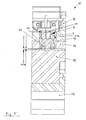
- FIG. 5 shows an injection molding machine 10 for the production of plastic moldings with four of a plastic molding material to be encapsulated partially electrical contact elements 21, 21 a of a plug-in contact.
- the machine comprises an insert 8 of a first tool part, which has a cavity into which the flexible sealing element 1 is inserted.
- the insert 8 has a wall 11 which separates the cavity from a cavity into which the plastic compound can be injected.
- the cavity is formed by the first and a second tool part.
- the wall 11 has four openings 12 for passing the electrical contact elements 21, 21 a, which are aligned with the slots 2, 2 a of the sealing element 1.
- the first tool part comprises a pressure piece 13, which rests against this in the inserted state of the sealing element 1.
- the pressure piece 13 is formed as a pressure plate, which rests against the front side facing away from the cavity 3 of the sealing element 1. Furthermore, the injection molding machine 10 comprises an intermediate plate 15, a clamping plate 16 and a mold plate 14, the latter rests against the insert 8 and has a recess aligned with the cavity, in which the pressure plate 13 is inserted.
- two grub screws 17 are introduced, with which the force exerted by the pressure plate 13 on the sealing element 1 pressure can be adjusted.
- two threads are provided in the pressure plate 13, in which engage the grub screws 17 and are mechanically connected to the power transmission with this.
- the pressure exerted on the sealing element 1 compressive force can be adjusted by how far the grub screws 17 protrude from the pressure plate 13, wherein the pressure plate 13 is flush in the relaxed state of the sealing element 1 flush with the mold plate 14.
- the grub screws 17 screwed so far into the pressure plate 13, that they still stick out about 0.8 millimeters, and thus protrude from the cavity of the surface facing away from the mold plate 14.
- This measure represents a path length B, by which the pressure plate 13 is moved against the sealing element 1.
- the maximum path length A for example, 2 millimeters can be adjusted by the grub screws 17 are further unscrewed from the sealing plate 13.
- the intermediate plate 15 rests flush against the mold plate 14, ie on the mold plate surface remote from the cavity and on the grub screws 17, ie presses the grub screws 17 together with the pressure plate 13 against the sealing element 1, which in turn is pressed against the partition wall 11, which has a counter-pressure on the sealing element 1.
- Pressure and back pressure are in FIG. 3 represented by the arrows F.
- the displaced volume of the sealing element 1 flows into free spaces and seals the contact elements 21, 21a located in the recesses 2, 2a toward the cavity and compensates for irregularities on the contact elements 21, 21a.
- the sealing process takes place automatically when closing the injection molding machine 10, ie, when the intermediate plate 15 rests against the mold plate 17.
- the sealing effect can be effected in an intelligent interaction with the tool closing movement.
- the sealing effect can also be triggered independently of the closing movement, for example by core pullers, jaw drives or other hydraulic or pneumatic switching elements.
- the sealing element 1 can then remain in the injection molding machine 10 for the next injection molding and thus be reused. Due to the sealing effect of the sealing element 1 remain at the contact elements 21, 21 a no clearances, can flow into the plastic material, so that a degree is avoided. Elaborate post-processing steps can be saved.
Landscapes
- Engineering & Computer Science (AREA)
- Manufacturing & Machinery (AREA)
- Mechanical Engineering (AREA)
- Injection Moulding Of Plastics Or The Like (AREA)
- Moulds For Moulding Plastics Or The Like (AREA)
Abstract
Description
- Die vorliegende Erfindung betrifft ein Dichtelement für eine Spritzgießmaschine zur Abdichtung zumindest eines elektrischen Kontaktelements eines Steckkontaktes beim teilweisen Umspritzen mit einer Kunststoffformmasse, eine Spritzgießmaschine zum Herstellen des das Kontaktelement umfassenden Steckkontakts eines Kunststoffformteils und ein Verfahren zur Herstellung des Steckkontaktes des Kunststoffformteils.
- Es ist häufig notwendig, Kunststoffformteile mit elektrischen Steckkontakten auszubilden, die eine elektrische Schnittstelle zu anderen elektrischen Bauteilen darstellen. Beispielsweise benötigt ein in ein Gehäuse integriertes elektrisches Bauteil im Falle des Betriebs an einem Spannungsnetz stets einen elektrischen Anschluss. Dieser kann vorteilhaft direkt an dem Gehäuse als einstückig mit diesem ausgebildeter Stecker vorgesehen werden. In das üblicherweise als Kunststoff hergestellte Gehäuse werden dann elektrische Verbindungsleiter eingebettet, die beidseitig aus dem Gehäuse herausragen, wobei ein erstes freies Ende der Verbindungsleiter ein Kontaktelement des Steckers bildet und das zweite freie Ende in den Innenraum des Gehäuses ragt, wo es für das elektrische Bauteil entweder ebenfalls über eine Steckverbindung oder direkt durch Verlöten kontaktiert werden kann.
- Weiterhin ist es auch bekannt, elektrische Bauteile, beispielsweise Statoren von Elektromotoren für Pumpenanwendungszwecke vollständig mit einem Kunststoff, beispielsweise einem Thermoplast oder einem Duroplast zu umspritzen. Derartige Bauteile weisen ebenfalls elektrische Steckkontakte auf, um mit einer anderen elektrischen Komponente, zum Beispiel einer Steuerungseinheit oder einem Frequenzumrichter verbunden und bestromt werden zu können. Dabei werden metallische Leiter verwendet, beispielsweise Stanzgitter oder einzelne im Querschnitt als Rund- oder Rechteckprofil ausgebildete Verbindungsleiter, die in die Kunststoffumspritzung eingebettet werden und lediglich an einem freien Ende im Bereich des Steckkontaktes aus dem Kunststoffformteil mit einem Kontaktierbereich herausragen. Das andere Ende des Verbindungsleiters ist an das elektrische Bauteil unmittelbar oder mittelbar angeschlossen.
- Zur Herstellung derartiger Kunststoffformteile werden die metallischen Verbindungsleiter zunächst in ein Spritzgießwerkzeug eingelegt und anschließend partiell umspritzt, womit sich eine Kunststoff-Metall-Verbundkonstruktion ergibt, die entsprechend der mit der Kunststoffformmasse zu füllenden Kavität des Werkzeugs beliebig komplex ausgebildet sein kann. Damit das für den Steckkontakt vorgesehene freie Ende eines Verbindungsleiters, nachfolgend Kontaktelement genannt, nicht mit Formmasse benetzt wird, muss dieses Ende aus der Kavität herausragen bzw. in einen Bereich hineinragen, in den die Formmasse nicht fließen kann.
- Hierfür ist es bekannt, im Formwerkzeug einen Einsatz aus Metall oder einem thermoplastischen Kunststoff mit einer oder gemäß der Anzahl abzudichtender Kontaktelemente entsprechend mehreren Öffnungen vorzusehen, in die das jeweilige freie Ende des Verbindungsleiters formschlüssig eingesteckt werden kann und so von der Umspritzung verschont bleibt. Nachteilig ist hierbei, dass aufgrund von Toleranzen in den Abmaßen und Abständen der Kontaktelemente keine vollständige Abdichtung zwischen dem Verbindungsleiter und dem Einsatz erreicht wird, so dass sich Freiräume bilden. Bei dünnflüssigen und leichtfließenden Formmassen werden diese Freiräume gefüllt und es bildet sich ein Grad. Da dieser Grad die Oberfläche des Kontaktierbereichs und damit aufgrund der Isoliereigenschaft des Kunststoffs die elektrische Übertragungsqualität reduziert, ist es notwendig, den Grad zu entfernen. Dies führt zu zusätzlichem personellen und zeitlichen Aufwand und damit zu erhöhten Herstellungskosten. Ein weiterer Nachteil ist bei der Ausführung des Einsatzes aus Metall, dass die ebenfalls metallischen Verbindungsleiter beim Einführen in die Öffnung beschädigt oder verbogen werden könnten. Ein thermoplastischer Einsatz hat ferner den Nachteil, dass er sich unter der Temperatur und dem Druck der eingespritzten Formmasse verformen könnte und somit nicht beliebig oft verwendet werden kann.
- Es ist daher Aufgabe der Erfindung, eine Möglichkeit zur Verfügung zu stellen, die Kontaktelemente eines Steckkontaktes eines Kunststoffformteiles beim partiellen Umspritzen in der Spritzgießmaschine mit einer Kunststoffformmasse derart abzudichten, dass sich keine Freiräume zwischen dem Einsatz und dem Kontaktelement bilden, so dass ein zeit-, personal- und kostenintensive Nacharbeitungsvorgang der Gradentfernung entfallen kann.
- Diese Aufgabe wird durch ein Dichtelement nach Anspruch 1, eine Spritzgießmaschine nach Anspruch 10 und das Verfahren nach Anspruch 12 gelöst. Vorteilhafte Weiterbildungen der Erfindung sind in den jeweiligen Unteransprüchen genannt.
- Erfindungsgemäß wird ein Dichtelement für eine Spritzgießmaschine zur Abdichtung zumindest eines elektrischen Kontaktelements eines Steckkontaktes beim teilweisen Umspritzen mit einer Kunststoffformmasse vorgeschlagen, das aus einem flexiblen Material gebildet ist und zumindest einen Schlitz aufweist, in das das Kontaktelement derart formschlüssig einführbar ist, dass es umfangsmäßig von dem Dichtelement vollständig umschlossen ist, wobei sich das Dichtelement bei Einwirkung einer Druckkraft derart elastisch verformt, dass es sich dichtend an das Kontaktelement anlegt.
- Ein derartiges Dichtelement kann in eine Spritzgießmaschine eingeführt werden und den Kontaktierbereich des zumindest einen elektrischen Kontaktelements vollständig abdichten, so dass keine Kunststoffformmasse beim Spritzgießen an dem Kontaktelement vorbeifließt. Dies wird dadurch erreicht, dass das Dichtelement aus einem flexiblen Material hergestellt wird, welches sich bei Ausübung einer Druckkraft auf das Dichtelement elastisch verformt. Die Innenwand des zumindest einen Schlitzes wird durch die Verformung allseitig gegen den Kontaktierbereich des Kontaktelements gedrückt und dichtet somit den gesamten Umfang des Kontaktelements, insbesondere zur Kavität des Spritzgießwerkzeugs hin ab. Es verbleiben keine Freiräume zwischen dem Dichtelement und dem Kontaktelement, in die etwaige Kunststoffformmasse eintreten kann und nach dem Abkühlen einen Grad bilden würde. Zeit- und arbeitsaufwändige Nachbearbeitungsschritte können dadurch entfallen und damit die Herstellungskosten des Kunststoffformteils erheblich reduziert werden. Weiterer Vorteil eines flexiblen Dichtelements ist, dass die Oberfläche des Kontaktelements, die zur Erzielung einer besseren elektrischen Leitfähigkeit gegebenenfalls besonders ausgebildet, beispielsweise vergoldet oder galvanisiert sein kann und damit empfindlich ist, nicht beschädigt wird. Das Dichtelement ist einteilig und kann nach dem Spritzgießvorgang in der Spritzgießmaschine verbleiben. Das Dichtelement bildet keinen Bestandteil des herzustellenden Steckkontakts.
- Das Kontaktelement kann aus einem beliebigen elektrisch leitenden Material, Verbundmaterial, insbesondere aus einem Metall, einer Metalllegierung oder einem metallbeschichteten Material bestehen. Zur Verwendung in einem Steckkontakt weist es eine länge Form auf, die im Querschnitt rund oder rechteckig sein kann. Ein derartiges Kontaktelement kann damit als Rundstift oder Flachstecker ausgebildet sein, d.h. einen stift- oder zungenförmigen Kontaktbereich aufweisen, den es beim Spritzgießvorgang abzudichten gilt.
- Je nach Ausbildung des zumindest einen Kontaktelements kann das Dichtelement an die Form des Kontaktelements angepasst sein. Bei Verwendung eines flachen Kontaktelements kann es genügen, das Dichtelement mit einem Schlitz in Form eines Einschnitts zu versehen, in den das Kontaktelement eingeschoben wird und der sich durch das Einschieben aufweitet. Der Schlitz wird dann von zwei sich gegenüberliegenden Lippen gebildet, die an den beiden breiten Kontaktflächen des Kontaktelements anliegen. Da die Lippen bei einem derartigen Schlitz im entspannten Zustand des Dichtelements bereits aneinander anliegen, bringt das Dichtelement dem Kontaktelement beim Einschieben eine gewisse Gegenkraft entgegen, da das Kontaktelement gummielastisches Material des Dichtelements in Höhe seines Volumens verdrängen muss. Die Rückstellkraft bewirkt dabei bereits eine erste Dichtwirkung zwischen Kontaktelement und Dichtelement. Aufgrund der Oberflächenadhäsion des flexiblen Dichtelements bringt dieses dem Kontaktelement ferner eine Reibkraft beim Einschieben in den Schlitz, d.h. beim planparallelen Bewegen der Kontaktelementoberflächen zu den Lippenoberflächen entgegen. Wird das Dichtelement zur Abdichtung mehrerer Kontaktelemente verwendet, die parallel zueinander beispielsweise in einer oder zwei Reihen angeordnet sind, führt diese zu überwindende Reibkraft zu erhöhtem Kraftaufwand. Dieser Kraftaufwand ist umso höhe, je dicker das Kontaktelement ausgebildet ist.
- Es kann daher erfindungsgemäß vorgesehen sein, den zumindest einen Schlitz als Ausnehmung auszubilden. Dies bedeutet, dass Material des Dichtelements zur Aufnahme des Kontaktelements entfernt ist. Der Querschnitt der Ausnehmung ist dabei an den Querschnitt des elektrischen Kontaktelements angepasst, insbesondere zur Ausbildung einer formschlüssigen Aufnahme des Kontaktelements in dem Dichtelement, so dass das Kontaktelement im zusammengesetzten Zustand an der Innenseite der Ausnehmung vollständig anliegt. Der Formschluss oder Reibschluss eines in den Schlitz eingebrachten Kontaktelements hat den Vorteil, dass das Kontaktelement in dem Dichtelement gehalten wird und kein zusätzliches Haltemittel notwendig ist, um das Kontaktelement in Bezug zur Kavität in Position zu halten.
- Alternativ kann die Ausnehmung in ihrem Querschnitt eine geringfügig größere Abmessung aufweisen als die äußere Abmessung des Kontaktelements. Dies hat den Vorteil, dass das Kontaktelement ohne Kraftaufwand in das Dichtelement eingebracht werden kann. Zwar ergibt sich dadurch ein geringer Freiraum zwischen der Innenwand der Ausnehmung und dem Kontaktelement, beispielsweise in Höhe weniger Zehntelmillimeter, jedoch sich kann das Dichtelement bei Wahl eines ausreichend elastischen Materials und unter Einwirkung einer Druckkraft ausreichend elastisch verformen, so dass es sich dichtend an das Kontaktelement anlegt und die Freiräume verschließt. Der sich zunächst ergebende Freiraum hat den zusätzlichen Vorteil, dass bei der Abdichtung mehrerer, in einer Reihe angeordneter Kontaktelemente Toleranzen in ihren Abständen ausgeglichen werden können.
- Das Dichtelement kann vorzugsweise aus einem Elastomer, insbesondere einem Silikon, gebildet sein. Das Elastomer stellt ein gummielastisches Material dar, welches durch seine elastische Verformung bei Druckausübung hervorragende Abdichwirkung aufweist. Es kann weich ausgebildet sein, was zu einer besonders hohen Dichtwirkung führt, aber auch hart ausgebildet sein, so dass der Verschleiß des Dichtelements in Folge scharfkantiger Kontaktelemente gering ist. Eine bevorzugte Materialwahl ist ein mittelmäßig weiches, bzw. hartes Elastomer, welches beide Vorteile kompromissgemäß verbindet. Ein Silikon hat den Vorteil, dass es aufgrund seiner glatten Oberfläche nicht an dem Gießmaterial haftet, welches an der Einführseite des Dichtelements mit diesem in Berührung kommt. Dies ermöglicht es, das Dichtelement - im Rahmen des mechanischen Verschleißes durch scharfe Kanten des Kontaktelements- beliebig oft wiederzuverwenden, so dass es dauerhaft in der Spritzgießmaschine verbleiben kann.
- Das Dichtelement kann im Querschnitt im Wesentlichen quaderförmig ausgebildet sein. Es bildet damit ein Bauteil, das besonders einfach in eine Spritzgießmaschine, insbesondere in einen für das Dichtelement vorgesehen Hohlraum, eingesetzt werden kann.
- Die Ausnehmung und/ oder der Einschnitt kann sich in Einführrichtung des Kontaktelements entlang der gesamten Dicke des Dichtelements erstrecken. Dies bedeutet, dass der Schlitz in dem Dichtelement durchgehend ist. Ein derartiges Dichtelement kann zum einen einfacher hergestellt werden als ein Dichtelement, in welchem sich der Schlitz nur teilweise in Richtung der Dicke erstreckt. Zum anderen kann das Dichtelement von beiden Stirnseiten, die die Schlitzöffnung aufweisen, auf das Kontaktelement geschoben werden, soweit keine Vorzugsorientierung notwendig ist. Dies vereinfacht die Handhabung und ermöglicht es, das Dichtelement weiter zu benutzen, wenn die erste Stirnseite in Folge intensiver Benutzung verschlissen ist. Ein weiterer Vorteil eines durchgehenden Schlitzes ist, dass das Dichtelement keine axialen Kräfte auf das Kontaktelement ausübt und das Kontaktelement damit nicht wieder aus dem Dichtelement herausgeschoben wird. Bei Druckbeaufschlagung der Stirnseite des Dichtelements wird auf das Kontaktelement lediglich eine radial zu diesem wirkende Kraft aufgebracht.
- In Einführrichtung sollte das Dichtelement eine Dicke aufweisen, die größer ist als die axiale Länge des Kontaktierbereichs des Kontaktelements. Dies gewährleistet, dass bei Ausübung einer Druckkraft auf die dem Einführende abgewandte Stirnseite des Dichtelements und der damit verbundenen Verdrängung von Dichtmaterial keine Beschädigung des Kontakteelements erfolgt. Das Dichtelement kann vorzugsweise eine Dicke zwischen 8 und 20 Millimeter betragen.
- Weiterhin kann das Dichtelement senkrecht zur Einführrichtung eine Breite zwischen 8 und 12 Millimeter aufweisen. In Kombination mit einer Dicke zwischen 8 und 20 Millimeter wird dadurch gewährleitet, dass genügend Dichtmaterial vorhanden ist, damit das Dichtelement eine ausreichende Rückstellkraft aufbringen kann.
- Das vorzugsweise im Wesentlichen quaderförmige Dichtelement kann weiterhin vorzugsweise zumindest eine zur Einführrichtung parallele Seitenkante aufweisen, die gegenüber den anderen Seitenkanten anders geformt ist. Damit wird eine Vorzugsrichtung definiert, gemäß derer das Dichtelement in die Spritzgießmaschine einzusetzen ist. Beispielsweise kann eine oder können drei der Seitenkanten abgerundet sein, wohingegen die andere oder die anderen Seitenkanten einen ausgefüllten rechten Winkel bilden.
- Da ein Steckkontakt regelmäßig mehr als ein elektrisches Kontaktelement aufweist, kann das Dichtelement dafür vorgesehen sein, mehrere elektrische Kontaktelemente beim Spritzgießvorgang abzudichten. Hierzu kann es mehrere Schlitze, d.h. Einschnitte und/ oder Ausnehmungen aufweisen, die parallel zueinander ausgerichtet sind.
- Erfindungsgemäß wird weiterhin eine Spritzgießmaschine zur Herstellung von Kunststoffformteilen mit zumindest einem von einer Kunststoffformmasse teilweise zu umspritzenden elektrischen Kontaktelement eines Steckkontakts vorgeschlagen, mit einem Einsatz eines ersten Werkzeugteils, der einen Hohlraum aufweist, in den das erfindungsgemäße flexible Dichtelement mit zumindest einem Schlitz einsetzbar ist, wobei der Einsatz eine Wand aufweist, die den Hohlraum von einer Kavität trennt, in die die Kunststoffmasse einspritzbar ist, wobei die Wand zumindest eine Öffnung zur Durchführung des elektrischen Kontaktes aufweist, die auf den Schlitz des Dichtelements ausgerichtet ist, und mit einem Druckstück, das im eingesetzten Zustand des Dichtelements an diesem anliegt, wobei das Spritzgießwerkzeug zumindest während des Spritzgießbetriebs eine Druckkraft auf das Druckstück ausübt. Durch das Anliegen des Druckstücks an dem Dichtelement wird die Druckkraft auf das Dichtelement übertragen. Da es flexibel ausgebildet ist, wird es elastisch verformt. Dies bewirkt wiederum, dass das Dichtelement an die Trennwand gedrückt wird und dort im Bereich der Öffnung ein eingeführtes Kontaktelement zur Kavität hin abdichtet, so dass keine Kunststoffformasse aus der Kavität entlang des Kontaktelements fließen kann und eine Gradbildung so verhindert wird.
- Das Druckstück kann eine Druckplatte sein, die an der der Kavität abgewandten Stirnseite des Dichtelements anliegen kann. Auf diese Weise wird eine gleichmäßige Kraft auf das Dichtelement ausgeübt, so dass ein gleichmäßiges Anliegen des Dichtelements am Umfang des Kontaktelements erreicht wird.
- Erfindungsgemäß wird weiterhin ein Verfahren zur Herstellung eines Steckkontakts bei einem Kunststoffformteil durch teilweises Umspritzen zumindest eines elektrischen Kontaktelements mit einer Kunststoffformmasse vorgeschlagen, umfassend die Schritte
- Einsetzen eines erfindungsgemäßen flexiblen Dichtelements mit zumindest einem Schlitz in einen Hohlraum eines Einsatzes eines erfindungsgemäßen Spritzgießwerkzeugs,
- Einführen des zumindest einen Kontaktelements in den Schlitz derart, dass es umfangsmäßig von dem Dichtelement vollständig umschlossen ist,
- Schließen des Spritzgießwerkzeugs unter Ausbildung einer Kavität,
- Einspritzen der Kunststoffformmasse in die Kavität unter gleichzeitiger Ausübung einer Druckkraft auf das Dichtelement derart, dass das Dichtelement an das Kontaktelement angepresst wird und das Kontaktelement zur Kavität hin vollständig abdichtet,
- Öffnen des Spritzgießwerkzeugs,
- Entformen des Kunststoffformteils.
- Die Druckkraft kann vorzugsweise auf der der Kavität abgewandten Stirnseite des Dichtelements ausgeübt werden, so dass das Dichtelement auf die Trennwand gedrückt wird. Durch diese Kraftausübung wird das Dichtelement derart verformt, dass im Falle eines Einschnitts als Schlitz die Lippen aufeinander gepresst werden und im Falle einer Ausnehmung die Innenwände der Ausnehmung sich nach innen in die Ausnehmung wölben. Auf diese Weise wird ein in den Schlitz eingebrachtes Kontaktelement fixiert und abgedichtet. Der auf das Kontaktelement ausgeübte Druck wirkt senkrecht zur Einführrichtung.
- Besonders vorteilhaft ist es, wenn die Druckkraft durch Andrücken einer Druckplatte gegen die Stirnseite des Dichtelements ausgebübt wird. Damit wird eine gleichmäßige Druckverteilung und folglich eine gleichmäßige Abdichtung des Kontaktelements erreicht.
- Vorzugsweise kann die Druckkraft durch die Schließbewegung des Spritzgießwerkszeugs, d.h. die Zusammenführung des ersten und eines zweiten die Kavität ausbildenden Werkzeugteils durch geeignete Mittel automatisch aufgebracht werden. Hierdurch erfolgt eine Fixierung und eine Abdichtung des Kontaktelements rechtzeitig vor dem Spritzgießprozess. In einer vorteilhaften Weiterbildung kann die Druckkraft mit dem Öffnen des Spritzgießwerkzeugs, d.h. dem Auseinanderfahren des ersten und des zweiten Werkzeugteils, nachlassen, so dass sich das Dichtelement entspannt und das Kontaktelement zur Herausnahme freigibt.
- Die Erfindung wird nachfolgend anhand der beigefügten Zeichnungen näher erläutert.
- Es zeigen:
-
Fig. 1 : perspektivische Ansicht des Dichtelements -
Fig. 2 : Stirnseitenansicht des Dichtelements in eingesetztem Zustand -
Fig. 3 : Längsseitenansicht des Dichtelements -
Fig. 4 : Querseitenansicht des Dichtelements -
Fig. 5 : Spritzgießwerkzeug mit Dichtelement -
Figur 1 zeigt das erfindungsgemäße Dichtelement 1 für eine Spritzgießmaschine 10 zur Abdichtung zumindest eines nicht dargestellten elektrischen Kontaktelements 21, 21a eines Steckkontaktes beim partiellen Umspritzen mit einer leicht-fließenden, insbesondere einer duroplastischen Kunststoffformmasse in perspektivischer Darstellung. Das Dichtelement 1 ist aus einem Gusssililkon hergestellt, das temperaturbeständig ist und auch bei hohen Temperaturen ein hohes Rückstellvermögen und damit eine gute Dichtwirkung gewährleistet. Es kann durch verschiedene Härten, beispielsweise 55 Shore oder 80 Shore an die jeweiligen Erfordernisse angepasst werden. - Das Dichtelement 1 weist vier Schlitze in Gestalt länglicher Ausnehmungen 2, 2a auf, in die vier korrespondierende Kontaktelemente 21, 21a eingeführt werden können. Die Kontaktelemente 21, 21a sind in dieser Ausführungsvariante in Gestalt von Kontaktzungen ausgeführt, die von dem Dichtelement 1 umschlossen werden. Alternativ können jedoch auch andere Profile Verwendung finden, beispielsweise Kontaktstifte runden oder quadratischen Querschnitts, wobei in diesem Fall die Ausnehmungen 2, 2a des Dichtelements 1 entsprechend an diese Form angepasst sind, um eine optimale Dichtwirkung zu erreichen.
- Soweit die Kontaktelemente in das Dichtelement 1 eingeführt werden, werden sie von diesem abgedichtet, so dass keine Kunststoffformmasse an diesen Teil gelangen kann. Dieser vom Dichtelement umschlossene Teil stellt den elektrischen Kontaktierbereich für den Steckkontakt des herzustellenden Kunststoffformteils dar.
- Das Dichtelement 1 ist im Wesentlichen quaderförmig. Es weist drei abgerundete Seitenkanten 4 und eine Seitenkante 5 auf, an der die linke Querseitenfläche 6 und die obere Längsseitenfläche 7 im rechten Winkel aneinander stoßen. Hierdurch wird dem Dichtelement 1 für das Einsetzen in die Spritzgießmaschine 10 eine Vorzugsrichtung verliehen.
-
Figur 2 zeigt eine Ansicht des Dichtelements 1 im in die Spritzgießmaschine 10 eingesetzten Zustand mit Blick auf die Stirnseite 3. Kontaktelemente 21, 21a sind in das Dichtelement 1 formschlüssig eingeführt und werden umfangsmäßig von dem Dichtelement 1 vollständig umschlossen. Die aus dem Dichtelement 1 hervorstehenden Endbereiche der Kontaktelemente 21, 21a ragen in die Kavität hinein und werden dort von der Kunststoffformmasse umspritzt. Die Kontaktelemente 21, 21a bilden somit metallische Einlegeteile. Von der Spritzgießmaschine 10 ist lediglich ein Einsatz 8 eines ersten Werkzeugteils im Querschnitt dargestellt, welches einen hohlen Aufnahmeraum aufweist, in den das Dichtelement 1 in geringem Abstand 9 zur Hohlrauminnenwand eingesetzt ist. Alternativ kann der Aufnahmeraum auch an die Abmessungen des Dichtelements 1 angepasst sein, so dass das Dichtelement formschlüssig in dem Aufnahmeraum einliegt. Die Innenflächen des Aufnahmeraums bilden dann beim Einsetzen des Dichtelements 1 in den Aufnahmeraum Gleitflächen. - Das Dichtelement 1 wird von den Kontaktelementen 21, 21a gehalten. In
Figur 2 ist ein Kontaktelement 21a dargestellt, welches breiter ausgebildet ist, als die übrigen Kontaktelemente 21. Diese Unsymmetrie in der Kontaktelementanordnung bedingt eine bestimmte Orientierung des Dichtelements 1 beim Einführen der Kontaktelemente 21, 21a in die Schlitze 2, 2a. Die korrekte Orientierung wird durch die Lage der nichtabgerundeten Seitenkante 5 vorgegeben. -
Figur 3 zeigt eine Ansicht auf die obere Längsseitenfläche 7 des Dichtelements 1. Die gestrichelten Linien deuten die Ausnehmungen 2 im Dichtelement 1 an. Die durchgezogenen Linien zeigen die Kontur des Dichtelements, insbesondere im Bereich der abgerundeten Seitenkanten 4. Die Figur zeigt, dass sich die Ausnehmung 2, 2a entlang der gesamten Dicke des Dichtelements 1 in Einführrichtung der Kontaktelemente 21, 21 a erstrecken. Die Dicke ist größer als die axiale Länge des Kontaktierbereichs der Kontaktelemente 21, 21a und beträgt ca. 9 Millimeter. Weiterhin beträgt die Breite des Dichtelements 1, d.h. seine Erstreckung in Querrichtung senkrecht zur Einführrichtung, ca. 8 Millimeter.Figur 3 zeigt weiterhin die in Richtung der Pfeile F auf das Dichtelement 1 ausgeübte Kraft zur derartigen elastischen Verformung, dass sich das Dichtelement 1 dichtend an die Kontaktelemente 21, 21 a anlegt. Die Richtung, in der die Kraft ausgeübt wird, entspricht dabei der Einführrichtung der Kontaktelemente 21, 21a in die Ausnehmungen 2, 2a. -
Figur 4 zeigt eine Ansicht auf die inFigur 1 nicht sichtbare Querseitenfläche. Die gestrichelten Linien deuten auch hier die Ausnehmungen 2, 2a im Dichtelement 1 an. Die unterschiedlichen Breiten der Ausnehmungen 2 für die Kontaktelemente 21 und der Ausnehmung 2a für das Kontaktelement 21a sind erkennbar. -
Figur 5 zeigt eine Spritzgießmaschine 10 zur Herstellung von Kunststoffformteilen mit vier von einer Kunststoffformmasse teilweise zu umspritzenden elektrischen Kontaktelementen 21, 21 a eines Steckkontakts. Die Maschine umfasst einen Einsatz 8 eines ersten Werkzeugteils, der einen Hohlraum aufweist, in den das flexible Dichtelement 1 eingesetzt ist. Der Einsatz 8 weist eine Wand 11 auf, die den Hohlraum von einer Kavität trennt, in die die Kunststoffmasse einspritzbar ist. Die Kavität wird von dem ersten und einem zweiten Werkzeugteil gebildet. Die Wand 11 hat vier Öffnungen 12 zur Durchführung der elektrischen Kontaktelemente 21, 21a, die auf die Schlitze 2, 2a des Dichtelements 1 ausgerichtet sind. Weiterhin umfasst das erste Werkzeugteil ein Druckstück 13, das im eingesetzten Zustand des Dichtelements 1 an diesem anliegt. Das Druckstück 13 ist als Druckplatte ausgebildet, die an der der Kavität abgewandten Stirnseite 3 des Dichtelements 1 anliegt. Des Weiteren umfasst die Spritzgießmaschine 10 eine Zwischenplatte 15, eine Aufspannplatte 16 und eine Formplatte 14, wobei Letztere an dem Einsatz 8 anliegt und eine zum Hohlraum fluchtende Ausnehmung aufweist, in der die Druckplatte 13 eingesetzt ist. - In die Druckplatte 13 sind zwei Madenschrauben 17 eingebracht, mit denen der von der Druckplatte 13 auf das Dichtelement 1 ausgeübte Druck eingestellt werden kann. Hierzu sind in der Druckplatte 13 zwei Gewinde vorgesehen, in die die Madenschrauben 17 eingreifen und zur Kraftübertragung mechanisch mit dieser Verbunden sind. Die auf das Dichtelement 1 ausgeübte Druckkraft kann dadurch eingestellt werden, wie weit die Madenschrauben 17 aus der Druckplatte 13 herausragen, wobei die Druckplatte 13 im entspannten Zustand des Dichtelements 1 bündig mit der Formplatte 14 abschließt. Dabei sind in
Figur 5 die Madenschrauben 17 so weit in die Druckplatte 13 eingeschraubt, dass sie noch ca. 0,8 Millimeter herausstehen, und damit von der der Kavität abgewandten Oberfläche der Formplatte 14 hervorstehen. Dieses Maß stellt eine Weglänge B dar, um die die Druckplatte 13 gegen das Dichtelement 1 bewegt wird. Als maximale Weglänge A können beispielsweise 2 Millimeter eingestellt werden, indem die Madenschrauben 17 weiter aus der Dichtplatte 13 herausgeschraubt werden. Die Zwischenplatte 15 liegt für den Betrieb der Maschine 10 bündig an der Formplatte 14, d.h. an der der Kavität abgewandten Formplattenoberfläche und an den Madenschrauben 17 an, d.h. drückt die Madenschrauben 17 samt Druckplatte 13 gegen das Dichtelement 1, welches wiederum gegen die Trennwand 11 gedrückt wird, die einen Gegendruck auf das Dichtelement 1 auswirkt. Druck und Gegendruck sind inFigur 3 mit den Pfeilen F dargestellt. Durch das Zusammendrücken wird das Dichtelement 1 in seiner Dicke um die Weglänge B verkürzt. Es kommt zu einer Verformung. Das verdrängte Volumen des Dichtelements 1 fließt in Freiräume und dichtet die in den Ausnehmungen 2, 2a befindlichen Kontaktelemente 21, 21a zur Kavität hin ab und gleicht Unregelmäßigkeiten an den Kontaktelementen 21, 21a aus. Der Abdichtvorgang erfolgt automatisch beim Schließen der Spritzgießmaschine 10, d.h., wenn sich die Zwischenplatte 15 an die Formplatte 17 anlegt. Über diesen speziellen einstellbaren Mechanismus kann die Dichtwirkung in intelligentem Zusammenspiel mit der Werkzeugschließbewegung bewirkt werden. Alternativ kann die Dichtwirkung aber auch unabhängig von der Schließbewegung ausgelöst werden, beispielsweise durch Kernzüge, Backenantriebe oder andere hydraulische oder pneumatische Schaltelemente. - Die folgenden Verfahrensschritte werden demgemäß für die Herstellung von Kunststoffformteilen mit den von einer Kunststoffformmasse teilweise zu umspritzenden elektrischen Kontaktelementen 21, 21a eines Steckkontakts bei der Verwendung der erfindungsgemäßen Maschine 10 ausgeübt:
- einmaliges Einsetzen des Dichtelements 1 in einen Hohlraum des Einsatzes 8,
- Einführen der Kontaktelemente 21, 21a in das Dichtelement 1 derart, dass sie umfangsmäßig von dem Dichtelement 1 vollständig umschlossen sind; es ragt lediglich derjenige Teil der Kontaktelemente 21, 21a in die Kavität hinein, der von der Kunststoffformmasse umspritzt werden soll,
- Schließen der Spritzgießwerkzeuge der Spritzgießmaschine 10 unter Ausbildung einer Kavität, wobei die Zwischenplatte 15 zur Anlage auf der Formplatte 14 gelangt, so dass eine Druckkraft auf die der Kavität abgewandten Stirnseite 3 des Dichtelements 1 derart ausgeübt wird, dass das Dichtelement 1 an die Kontaktelemente 21, 21a angepresst wird und die Kontaktelemente 21, 21a zur Kavität hin vollständig abgedichtet werden,
- Einspritzen der Kunststoffformmasse in die Kavität,
- Öffnen des Spritzgießwerkzeugs und
- Entformen des Kunststoffformteils mitsamt den umspritzten Kontaktelementen, 21, 21a.
- Das Dichtelement 1 kann anschließend in der Spritzgießmaschine 10 für den nächsten Spritzgießvorgang verbleiben und somit wiederverwendet werden. Durch die Dichtwirkung des Dichtelements 1 verbleiben an den Kontaktelementen 21, 21a keine Freiräume, in die Kunststoffmasse fließen kann, so dass eine Gradbildung vermieden wird. Aufwändige Nachbearbeitungsschritte können dadurch eingespart werden.
Claims (15)
- Dichtelement (1) für eine Spritzgießmaschine (10) zur Abdichtung zumindest eines elektrischen Kontaktelements (21, 21a) eines Steckkontaktes beim teilweisen Umspritzen mit einer Kunststoffformmasse, dadurch gekennzeichnet, dass es aus einem flexiblen Material gebildet ist und zumindest einen Schlitz (2, 2a) aufweist, in das das Kontaktelement (21, 21a) derart formschlüssig einführbar ist, dass es umfangsmäßig von dem Dichtelement (1) vollständig umschließbar ist, wobei sich das Dichtelement (1) bei Einwirkung einer Druckkraft derart elastisch verformt, dass es sich dichtend an das Kontaktelement (21, 21a) anlegt.
- Dichtelement (1) nach Anspruch 1, dadurch gekennzeichnet, dass der zumindest eine Schlitz (2, 2a) ein länglicher Einschnitt oder eine längliche Ausnehmung ist.
- Dichtelement (1) nach Anspruch 2, dadurch gekennzeichnet, dass es aus einem spritzgießfähigen Elastomer, insbesondere einem Silikon, gebildet ist.
- Dichtelement (1) nach Anspruch 1, 2 oder 3, dadurch gekennzeichnet, dass es im Querschnitt quaderförmig ausgebildet ist.
- Dichtelement (1) nach einem der vorherigen Ansprüche, dadurch gekennzeichnet, dass sich der Schlitz (2, 2a) entlang der gesamten Dicke des Dichtelements (1) in Einführrichtung des Kontaktelements (21, 21a) erstreckt.
- Dichtelement (1) nach einem der vorherigen Ansprüche, dadurch gekennzeichnet, dass es in Einführrichtung eine Dicke aufweist, die größer ist als die axiale Länge des Kontaktierbereichs des Kontaktelements (21, 21a), vorzugsweise zwischen 8 und 20 Millimeter beträgt.
- Dichtelement (1) nach einem der vorherigen Ansprüche, dadurch gekennzeichnet, dass es senkrecht zur Einführrichtung eine Breite zwischen 8 und 12 Millimeter aufweist.
- Dichtelement (1) nach einem der vorherigen Ansprüche, dadurch gekennzeichnet, dass es zumindest eine zur Einführrichtung parallele Seitenkante (5) aufweist, die gegenüber den anderen Seitenkanten (4) anders geformt ist, wobei insbesondere eine oder drei der Seitenkanten (4, 5) abgerundet ist/ sind.
- Dichtelement (1) nach einem der vorherigen Ansprüche, dadurch gekennzeichnet, dass es mehrere Schlitze (2, 2a) aufweist, die parallel zueinander ausgerichtet sind.
- Spritzgießmaschine (10) zur Herstellung von Kunststoffformteilen mit zumindest einem von einer Kunststoffformmasse teilweise zu umspritzenden elektrischen Kontaktelement (21, 21a) eines Steckkontakts, mit einem Einsatz (8) eines ersten Werkzeugteils, der einen Hohlraum aufweist, in den ein flexibles Dichtelement (1) nach einem der Ansprüche 1 bis 9 mit zumindest einem Schlitz (2, 2a) einsetzbar ist, wobei der Einsatz (8) eine Wand (11) aufweist, die den Hohlraum von einer Kavität trennt, in die die Kunststoffmasse einspritzbar ist, wobei die Wand (11) zumindest eine Öffnung (12) zur Durchführung des elektrischen Kontaktelementes (21, 21a) aufweist, die auf den Schlitz (2, 2a) des Dichtelements (1) ausgerichtet ist, und mit einem Druckstück (13), das im eingesetzten Zustand des Dichtelements (1) an diesem anliegt, wobei das Spritzgießwerkzeug (10) zumindest während Spritzgießbetriebs eine Druckkraft auf das Druckstück (13) ausübt.
- Spritzgießwerkzeug (10) nach Anspruch 10, dadurch gekennzeichnet, dass das Druckstück (13) eine Druckplatte ist, die an der der Kavität abgewandten Stirnseite (3) des Dichtelements (1) anliegt.
- Verfahren zur Herstellung eines Steckkontakts bei einem Kunststoffformteil durch teilweises Umspritzen zumindest eines elektrischen Kontaktelements (21, 21a) mit einer Kunststoffformmasse, umfassend die Schritte- Einsetzen eines flexiblen Dichtelements (1) nach einem der vorherigen Ansprüche 1 bis 9 mit zumindest einem Schlitz (2, 2a) in einen Hohlraum eines Einsatzes (8) einer Spritzgießmaschine (10) nach einem der Ansprüche 10 oder 11,- Einführen des zumindest einen Kontaktelements (21, 21a) in das Dichtelement (1) derart, dass es umfangsmäßig von dem Dichtelement (1) vollständig umschlossen ist,- Schließen der Spritzgießwerkzeuge der Spritzgießmaschine (10) unter Ausbildung einer Kavität,- Einspritzen der Kunststoffformmasse in die Kavität unter gleichzeitiger Ausübung einer Druckkraft auf das Dichtelement (13) derart, dass das Dichtelement (1) an das Kontaktelement (21, 21a) angepresst wird und das Kontaktelement (21, 21a) zur Kavität hin vollständig abdichtet,- Öffnen der Spritzgießwerkzeuge,- Entformen des Kunststoffformteils.
- Verfahren nach Anspruch 12, dadurch gekennzeichnet, dass die Druckkraft auf der der Kavität abgewandten Stirnseite (3) des Dichtelements (1) ausgeübt wird.
- Verfahren nach Anspruch 13, dadurch gekennzeichnet, dass die Druckkraft durch Andrücken einer Druckplatte (13) gegen die Stirnseite (3) des Dichtelements (1) ausgebübt wird.
- Verfahren nach einem der Ansprüche 12 bis 14, dadurch gekennzeichnet, dass die Druckkraft durch die Schließbewegung des Spritzgießwerkszeugs aufgebracht wird.
Applications Claiming Priority (1)
| Application Number | Priority Date | Filing Date | Title |
|---|---|---|---|
| DE200910011731 DE102009011731A1 (de) | 2009-03-09 | 2009-03-09 | Dichtelement zur Abdichtung elektrischer Kontaktelemente beim Spritzgießen |
Publications (3)
| Publication Number | Publication Date |
|---|---|
| EP2228191A2 true EP2228191A2 (de) | 2010-09-15 |
| EP2228191A3 EP2228191A3 (de) | 2014-05-21 |
| EP2228191B1 EP2228191B1 (de) | 2016-09-07 |
Family
ID=42199103
Family Applications (1)
| Application Number | Title | Priority Date | Filing Date |
|---|---|---|---|
| EP10001830.8A Active EP2228191B1 (de) | 2009-03-09 | 2010-02-23 | Dichtelement zur Abdichtung elektrischer Kontaktelemente beim Spritzgießen |
Country Status (2)
| Country | Link |
|---|---|
| EP (1) | EP2228191B1 (de) |
| DE (1) | DE102009011731A1 (de) |
Cited By (1)
| Publication number | Priority date | Publication date | Assignee | Title |
|---|---|---|---|---|
| EP4563318A4 (de) * | 2022-09-13 | 2026-01-28 | Nissha Co Ltd | Verfahren zur herstellung eines harzformartikels und harzformartikel |
Families Citing this family (1)
| Publication number | Priority date | Publication date | Assignee | Title |
|---|---|---|---|---|
| DE102020131220A1 (de) | 2020-11-25 | 2022-05-25 | Kolektor Group D.O.O. | Stator-Bauteil einer elektrodynamischen Maschine |
Family Cites Families (6)
| Publication number | Priority date | Publication date | Assignee | Title |
|---|---|---|---|---|
| DE1554882B1 (de) * | 1963-11-12 | 1971-12-09 | Siemens Ag | Verfaren und vorrichtung zur befestigung vonanschlussdrähten in einer halterungsplatte aus kunststoff für elektrischebauelemente |
| DE2312298A1 (de) * | 1973-03-13 | 1974-09-19 | Zettler Elektrotechn Alois | Werkzeug zum umspritzen oder umpressen von metallteilen |
| DE4328240C2 (de) * | 1993-08-19 | 1997-07-17 | Siemens Ag | Verfahren zur Herstellung eines Steckers und Spritzgießform zur Durchführung des Verfahrens |
| JP3411900B2 (ja) * | 2000-11-15 | 2003-06-03 | 東海興業株式会社 | コネクタ一体型ケースの成形方法 |
| DE102004016832B4 (de) * | 2004-04-01 | 2013-09-19 | Kunststoffinstitut für die mittelständische Wirtschaft NRW GmbH | Vorrichtung zum teilweisen Umspritzen metallischer Einleger mit einem Spritzgießwerkzeug |
| DE102004057810B4 (de) * | 2004-11-30 | 2008-08-07 | Webasto Ag | Kunststoffformteil und Verfahren zur Herstellung eines Kunststoffformteils |
-
2009
- 2009-03-09 DE DE200910011731 patent/DE102009011731A1/de not_active Withdrawn
-
2010
- 2010-02-23 EP EP10001830.8A patent/EP2228191B1/de active Active
Non-Patent Citations (1)
| Title |
|---|
| None |
Cited By (1)
| Publication number | Priority date | Publication date | Assignee | Title |
|---|---|---|---|---|
| EP4563318A4 (de) * | 2022-09-13 | 2026-01-28 | Nissha Co Ltd | Verfahren zur herstellung eines harzformartikels und harzformartikel |
Also Published As
| Publication number | Publication date |
|---|---|
| EP2228191B1 (de) | 2016-09-07 |
| EP2228191A3 (de) | 2014-05-21 |
| DE102009011731A1 (de) | 2010-09-16 |
Similar Documents
| Publication | Publication Date | Title |
|---|---|---|
| DE102010031771B4 (de) | Verbinderherstellungsverfahren, Formwerkzeug | |
| DE102010015092B4 (de) | Herstellungsverfahren für einen Geräteverbinder und Formstruktur dafür | |
| DE19844603B4 (de) | Flüssigkeitsdichter Stecker und Verfahren zur Herstellung desselben | |
| EP0158845B2 (de) | Steckerbuchse mit Isolierstoffummantelung sowie Vorrichtung für ihre Herstellung | |
| EP2232222B1 (de) | Kunststoffgehäuse mit integrierter steckerschnittstelle | |
| DE102012203222A1 (de) | Gehäuseteil für eine Antriebseinheit, sowie Verfahren und Werkzeug zur Herstellung eines solchen | |
| DE69516973T2 (de) | Wasserdichte Verbinder und Verfahren zu seinem Zusammenbau | |
| EP3472473A1 (de) | Verfahren zum verbinden zweier bauteile sowie bauteilanordnung | |
| DE10041812A1 (de) | Baueinheit und Verfahren zur Herstellung derselben | |
| EP3036797A1 (de) | Betätigungselement und anschlussklemme | |
| EP2228191B1 (de) | Dichtelement zur Abdichtung elektrischer Kontaktelemente beim Spritzgießen | |
| DE2900114A1 (de) | Spritzpressverfahren zum einkapseln von halbleitervorrichtungen | |
| EP1763917B1 (de) | Gehäuseteil für eine antriebseinheit, sowie verfahren und werkzeug zur herstellung eines solchen | |
| DE102017109899A1 (de) | Elektrischer Verbinder | |
| EP0548857B1 (de) | Vorrichtung zum Herstellen von flachen Kunststoff-Formstücken, beispielsweise Ausweiskarten | |
| DE202013102008U1 (de) | Vorrichtung zur Herstellung eines Bauteils mit Leiterbahnen, die ganz oder teilweise in Kunststoff eingebettet sind | |
| DE102009055925A1 (de) | Steckverbinderanordnung | |
| EP3815476B1 (de) | Elektronikmodul mit steckeranschluss | |
| EP3209475B1 (de) | Verfahren zur herstellung eines kunststoffbauteils und kunststoffbauteil | |
| EP3582240B1 (de) | Schlauchverschluss | |
| EP0741920B1 (de) | Elektrischer verbindungsteil einer zweiteiligen steckverbindung | |
| DE102021126738B3 (de) | Werkzeugsystem zum Kunststoff-Gießen einer Statorumspritzungg, Verfahren zum Kunststoff-Gießen mittels eines solchen Werkzeugsystems und eine mittels eines solchen Werkzeugsystems mit einer Statorumspritzung versehene Traktionsmaschine | |
| EP4074484B1 (de) | Einsatz, werkzeug, anlage und verfahren zur herstellung von formbauteilen mit hinterschnitt | |
| DE3809209A1 (de) | Isolierkoerper | |
| DE102019208997B4 (de) | Hinterschnittfrei ausgebildeter Kodierrahmen und Haushaltsgerät mit einem solchen Rahmen sowie Verfahren zur Herstellung eines Kodierrahmens |
Legal Events
| Date | Code | Title | Description |
|---|---|---|---|
| PUAI | Public reference made under article 153(3) epc to a published international application that has entered the european phase |
Free format text: ORIGINAL CODE: 0009012 |
|
| AK | Designated contracting states |
Kind code of ref document: A2 Designated state(s): AT BE BG CH CY CZ DE DK EE ES FI FR GB GR HR HU IE IS IT LI LT LU LV MC MK MT NL NO PL PT RO SE SI SK SM TR |
|
| AX | Request for extension of the european patent |
Extension state: AL BA RS |
|
| PUAL | Search report despatched |
Free format text: ORIGINAL CODE: 0009013 |
|
| AK | Designated contracting states |
Kind code of ref document: A3 Designated state(s): AT BE BG CH CY CZ DE DK EE ES FI FR GB GR HR HU IE IS IT LI LT LU LV MC MK MT NL NO PL PT RO SE SI SK SM TR |
|
| AX | Request for extension of the european patent |
Extension state: AL BA RS |
|
| RIC1 | Information provided on ipc code assigned before grant |
Ipc: B29C 45/26 20060101ALI20140416BHEP Ipc: B29C 45/14 20060101AFI20140416BHEP |
|
| 17P | Request for examination filed |
Effective date: 20141119 |
|
| RBV | Designated contracting states (corrected) |
Designated state(s): AT BE BG CH CY CZ DE DK EE ES FI FR GB GR HR HU IE IS IT LI LT LU LV MC MK MT NL NO PL PT RO SE SI SK SM TR |
|
| 17Q | First examination report despatched |
Effective date: 20150624 |
|
| GRAP | Despatch of communication of intention to grant a patent |
Free format text: ORIGINAL CODE: EPIDOSNIGR1 |
|
| INTG | Intention to grant announced |
Effective date: 20160513 |
|
| GRAS | Grant fee paid |
Free format text: ORIGINAL CODE: EPIDOSNIGR3 |
|
| GRAA | (expected) grant |
Free format text: ORIGINAL CODE: 0009210 |
|
| AK | Designated contracting states |
Kind code of ref document: B1 Designated state(s): AT BE BG CH CY CZ DE DK EE ES FI FR GB GR HR HU IE IS IT LI LT LU LV MC MK MT NL NO PL PT RO SE SI SK SM TR |
|
| REG | Reference to a national code |
Ref country code: GB Ref legal event code: FG4D Free format text: NOT ENGLISH |
|
| REG | Reference to a national code |
Ref country code: CH Ref legal event code: EP |
|
| REG | Reference to a national code |
Ref country code: IE Ref legal event code: FG4D Free format text: LANGUAGE OF EP DOCUMENT: GERMAN |
|
| REG | Reference to a national code |
Ref country code: AT Ref legal event code: REF Ref document number: 826440 Country of ref document: AT Kind code of ref document: T Effective date: 20161015 |
|
| REG | Reference to a national code |
Ref country code: DE Ref legal event code: R096 Ref document number: 502010012332 Country of ref document: DE |
|
| REG | Reference to a national code |
Ref country code: LT Ref legal event code: MG4D |
|
| REG | Reference to a national code |
Ref country code: NL Ref legal event code: MP Effective date: 20160907 |
|
| REG | Reference to a national code |
Ref country code: FR Ref legal event code: PLFP Year of fee payment: 8 |
|
| PG25 | Lapsed in a contracting state [announced via postgrant information from national office to epo] |
Ref country code: FI Free format text: LAPSE BECAUSE OF FAILURE TO SUBMIT A TRANSLATION OF THE DESCRIPTION OR TO PAY THE FEE WITHIN THE PRESCRIBED TIME-LIMIT Effective date: 20160907 Ref country code: HR Free format text: LAPSE BECAUSE OF FAILURE TO SUBMIT A TRANSLATION OF THE DESCRIPTION OR TO PAY THE FEE WITHIN THE PRESCRIBED TIME-LIMIT Effective date: 20160907 Ref country code: LT Free format text: LAPSE BECAUSE OF FAILURE TO SUBMIT A TRANSLATION OF THE DESCRIPTION OR TO PAY THE FEE WITHIN THE PRESCRIBED TIME-LIMIT Effective date: 20160907 Ref country code: NO Free format text: LAPSE BECAUSE OF FAILURE TO SUBMIT A TRANSLATION OF THE DESCRIPTION OR TO PAY THE FEE WITHIN THE PRESCRIBED TIME-LIMIT Effective date: 20161207 |
|
| PG25 | Lapsed in a contracting state [announced via postgrant information from national office to epo] |
Ref country code: LV Free format text: LAPSE BECAUSE OF FAILURE TO SUBMIT A TRANSLATION OF THE DESCRIPTION OR TO PAY THE FEE WITHIN THE PRESCRIBED TIME-LIMIT Effective date: 20160907 Ref country code: SE Free format text: LAPSE BECAUSE OF FAILURE TO SUBMIT A TRANSLATION OF THE DESCRIPTION OR TO PAY THE FEE WITHIN THE PRESCRIBED TIME-LIMIT Effective date: 20160907 Ref country code: ES Free format text: LAPSE BECAUSE OF FAILURE TO SUBMIT A TRANSLATION OF THE DESCRIPTION OR TO PAY THE FEE WITHIN THE PRESCRIBED TIME-LIMIT Effective date: 20160907 Ref country code: NL Free format text: LAPSE BECAUSE OF FAILURE TO SUBMIT A TRANSLATION OF THE DESCRIPTION OR TO PAY THE FEE WITHIN THE PRESCRIBED TIME-LIMIT Effective date: 20160907 Ref country code: GR Free format text: LAPSE BECAUSE OF FAILURE TO SUBMIT A TRANSLATION OF THE DESCRIPTION OR TO PAY THE FEE WITHIN THE PRESCRIBED TIME-LIMIT Effective date: 20161208 |
|
| PG25 | Lapsed in a contracting state [announced via postgrant information from national office to epo] |
Ref country code: EE Free format text: LAPSE BECAUSE OF FAILURE TO SUBMIT A TRANSLATION OF THE DESCRIPTION OR TO PAY THE FEE WITHIN THE PRESCRIBED TIME-LIMIT Effective date: 20160907 Ref country code: RO Free format text: LAPSE BECAUSE OF FAILURE TO SUBMIT A TRANSLATION OF THE DESCRIPTION OR TO PAY THE FEE WITHIN THE PRESCRIBED TIME-LIMIT Effective date: 20160907 |
|
| PG25 | Lapsed in a contracting state [announced via postgrant information from national office to epo] |
Ref country code: BG Free format text: LAPSE BECAUSE OF FAILURE TO SUBMIT A TRANSLATION OF THE DESCRIPTION OR TO PAY THE FEE WITHIN THE PRESCRIBED TIME-LIMIT Effective date: 20161207 Ref country code: PT Free format text: LAPSE BECAUSE OF FAILURE TO SUBMIT A TRANSLATION OF THE DESCRIPTION OR TO PAY THE FEE WITHIN THE PRESCRIBED TIME-LIMIT Effective date: 20170109 Ref country code: CZ Free format text: LAPSE BECAUSE OF FAILURE TO SUBMIT A TRANSLATION OF THE DESCRIPTION OR TO PAY THE FEE WITHIN THE PRESCRIBED TIME-LIMIT Effective date: 20160907 Ref country code: SK Free format text: LAPSE BECAUSE OF FAILURE TO SUBMIT A TRANSLATION OF THE DESCRIPTION OR TO PAY THE FEE WITHIN THE PRESCRIBED TIME-LIMIT Effective date: 20160907 Ref country code: SM Free format text: LAPSE BECAUSE OF FAILURE TO SUBMIT A TRANSLATION OF THE DESCRIPTION OR TO PAY THE FEE WITHIN THE PRESCRIBED TIME-LIMIT Effective date: 20160907 Ref country code: IS Free format text: LAPSE BECAUSE OF FAILURE TO SUBMIT A TRANSLATION OF THE DESCRIPTION OR TO PAY THE FEE WITHIN THE PRESCRIBED TIME-LIMIT Effective date: 20170107 Ref country code: PL Free format text: LAPSE BECAUSE OF FAILURE TO SUBMIT A TRANSLATION OF THE DESCRIPTION OR TO PAY THE FEE WITHIN THE PRESCRIBED TIME-LIMIT Effective date: 20160907 Ref country code: BE Free format text: LAPSE BECAUSE OF NON-PAYMENT OF DUE FEES Effective date: 20170228 |
|
| REG | Reference to a national code |
Ref country code: DE Ref legal event code: R097 Ref document number: 502010012332 Country of ref document: DE |
|
| PLBE | No opposition filed within time limit |
Free format text: ORIGINAL CODE: 0009261 |
|
| STAA | Information on the status of an ep patent application or granted ep patent |
Free format text: STATUS: NO OPPOSITION FILED WITHIN TIME LIMIT |
|
| PG25 | Lapsed in a contracting state [announced via postgrant information from national office to epo] |
Ref country code: DK Free format text: LAPSE BECAUSE OF FAILURE TO SUBMIT A TRANSLATION OF THE DESCRIPTION OR TO PAY THE FEE WITHIN THE PRESCRIBED TIME-LIMIT Effective date: 20160907 |
|
| 26N | No opposition filed |
Effective date: 20170608 |
|
| PG25 | Lapsed in a contracting state [announced via postgrant information from national office to epo] |
Ref country code: SI Free format text: LAPSE BECAUSE OF FAILURE TO SUBMIT A TRANSLATION OF THE DESCRIPTION OR TO PAY THE FEE WITHIN THE PRESCRIBED TIME-LIMIT Effective date: 20160907 |
|
| PG25 | Lapsed in a contracting state [announced via postgrant information from national office to epo] |
Ref country code: MC Free format text: LAPSE BECAUSE OF FAILURE TO SUBMIT A TRANSLATION OF THE DESCRIPTION OR TO PAY THE FEE WITHIN THE PRESCRIBED TIME-LIMIT Effective date: 20160907 |
|
| REG | Reference to a national code |
Ref country code: CH Ref legal event code: PL |
|
| PG25 | Lapsed in a contracting state [announced via postgrant information from national office to epo] |
Ref country code: LI Free format text: LAPSE BECAUSE OF NON-PAYMENT OF DUE FEES Effective date: 20170228 Ref country code: CH Free format text: LAPSE BECAUSE OF NON-PAYMENT OF DUE FEES Effective date: 20170228 |
|
| PG25 | Lapsed in a contracting state [announced via postgrant information from national office to epo] |
Ref country code: LU Free format text: LAPSE BECAUSE OF NON-PAYMENT OF DUE FEES Effective date: 20170223 |
|
| REG | Reference to a national code |
Ref country code: FR Ref legal event code: PLFP Year of fee payment: 9 |
|
| REG | Reference to a national code |
Ref country code: BE Ref legal event code: MM Effective date: 20170228 |
|
| REG | Reference to a national code |
Ref country code: AT Ref legal event code: MM01 Ref document number: 826440 Country of ref document: AT Kind code of ref document: T Effective date: 20170223 |
|
| PG25 | Lapsed in a contracting state [announced via postgrant information from national office to epo] |
Ref country code: AT Free format text: LAPSE BECAUSE OF NON-PAYMENT OF DUE FEES Effective date: 20170223 |
|
| PG25 | Lapsed in a contracting state [announced via postgrant information from national office to epo] |
Ref country code: MT Free format text: LAPSE BECAUSE OF FAILURE TO SUBMIT A TRANSLATION OF THE DESCRIPTION OR TO PAY THE FEE WITHIN THE PRESCRIBED TIME-LIMIT Effective date: 20160907 |
|
| REG | Reference to a national code |
Ref country code: IE Ref legal event code: MM4A |
|
| PG25 | Lapsed in a contracting state [announced via postgrant information from national office to epo] |
Ref country code: IE Free format text: LAPSE BECAUSE OF NON-PAYMENT OF DUE FEES Effective date: 20170223 |
|
| PG25 | Lapsed in a contracting state [announced via postgrant information from national office to epo] |
Ref country code: HU Free format text: LAPSE BECAUSE OF FAILURE TO SUBMIT A TRANSLATION OF THE DESCRIPTION OR TO PAY THE FEE WITHIN THE PRESCRIBED TIME-LIMIT; INVALID AB INITIO Effective date: 20100223 |
|
| PG25 | Lapsed in a contracting state [announced via postgrant information from national office to epo] |
Ref country code: CY Free format text: LAPSE BECAUSE OF NON-PAYMENT OF DUE FEES Effective date: 20160907 |
|
| PG25 | Lapsed in a contracting state [announced via postgrant information from national office to epo] |
Ref country code: MK Free format text: LAPSE BECAUSE OF FAILURE TO SUBMIT A TRANSLATION OF THE DESCRIPTION OR TO PAY THE FEE WITHIN THE PRESCRIBED TIME-LIMIT Effective date: 20160907 |
|
| PG25 | Lapsed in a contracting state [announced via postgrant information from national office to epo] |
Ref country code: TR Free format text: LAPSE BECAUSE OF FAILURE TO SUBMIT A TRANSLATION OF THE DESCRIPTION OR TO PAY THE FEE WITHIN THE PRESCRIBED TIME-LIMIT Effective date: 20160907 |
|
| PGFP | Annual fee paid to national office [announced via postgrant information from national office to epo] |
Ref country code: IT Payment date: 20210120 Year of fee payment: 12 |
|
| PG25 | Lapsed in a contracting state [announced via postgrant information from national office to epo] |
Ref country code: IT Free format text: LAPSE BECAUSE OF NON-PAYMENT OF DUE FEES Effective date: 20220223 |
|
| P01 | Opt-out of the competence of the unified patent court (upc) registered |
Effective date: 20230615 |
|
| REG | Reference to a national code |
Ref country code: DE Ref legal event code: R084 Ref document number: 502010012332 Country of ref document: DE |
|
| PGFP | Annual fee paid to national office [announced via postgrant information from national office to epo] |
Ref country code: GB Payment date: 20240123 Year of fee payment: 15 |
|
| PGFP | Annual fee paid to national office [announced via postgrant information from national office to epo] |
Ref country code: FR Payment date: 20240123 Year of fee payment: 15 |
|
| PGFP | Annual fee paid to national office [announced via postgrant information from national office to epo] |
Ref country code: DE Payment date: 20250122 Year of fee payment: 16 |
|
| GBPC | Gb: european patent ceased through non-payment of renewal fee |
Effective date: 20250223 |
|
| PG25 | Lapsed in a contracting state [announced via postgrant information from national office to epo] |
Ref country code: GB Free format text: LAPSE BECAUSE OF NON-PAYMENT OF DUE FEES Effective date: 20250223 |
|
| PG25 | Lapsed in a contracting state [announced via postgrant information from national office to epo] |
Ref country code: FR Free format text: LAPSE BECAUSE OF NON-PAYMENT OF DUE FEES Effective date: 20250228 |