EP2226918A2 - Stator für eine elektrische Drehmaschine - Google Patents
Stator für eine elektrische Drehmaschine Download PDFInfo
- Publication number
- EP2226918A2 EP2226918A2 EP10155289A EP10155289A EP2226918A2 EP 2226918 A2 EP2226918 A2 EP 2226918A2 EP 10155289 A EP10155289 A EP 10155289A EP 10155289 A EP10155289 A EP 10155289A EP 2226918 A2 EP2226918 A2 EP 2226918A2
- Authority
- EP
- European Patent Office
- Prior art keywords
- space
- slot
- connecting wire
- winding
- stator
- Prior art date
- Legal status (The legal status is an assumption and is not a legal conclusion. Google has not performed a legal analysis and makes no representation as to the accuracy of the status listed.)
- Granted
Links
Images


Classifications
-
- H—ELECTRICITY
- H02—GENERATION; CONVERSION OR DISTRIBUTION OF ELECTRIC POWER
- H02K—DYNAMO-ELECTRIC MACHINES
- H02K3/00—Details of windings
- H02K3/46—Fastening of windings on the stator or rotor structure
- H02K3/52—Fastening salient pole windings or connections thereto
- H02K3/521—Fastening salient pole windings or connections thereto applicable to stators only
- H02K3/522—Fastening salient pole windings or connections thereto applicable to stators only for generally annular cores with salient poles
-
- H—ELECTRICITY
- H02—GENERATION; CONVERSION OR DISTRIBUTION OF ELECTRIC POWER
- H02K—DYNAMO-ELECTRIC MACHINES
- H02K1/00—Details of the magnetic circuit
- H02K1/06—Details of the magnetic circuit characterised by the shape, form or construction
- H02K1/22—Rotating parts of the magnetic circuit
- H02K1/27—Rotor cores with permanent magnets
- H02K1/2706—Inner rotors
-
- H—ELECTRICITY
- H02—GENERATION; CONVERSION OR DISTRIBUTION OF ELECTRIC POWER
- H02K—DYNAMO-ELECTRIC MACHINES
- H02K15/00—Processes or apparatus specially adapted for manufacturing, assembling, maintaining or repairing of dynamo-electric machines
- H02K15/08—Forming windings by laying conductors into or around core parts
- H02K15/095—Forming windings by laying conductors into or around core parts by laying conductors around salient poles
-
- H—ELECTRICITY
- H02—GENERATION; CONVERSION OR DISTRIBUTION OF ELECTRIC POWER
- H02K—DYNAMO-ELECTRIC MACHINES
- H02K3/00—Details of windings
- H02K3/04—Windings characterised by the conductor shape, form or construction, e.g. with bar conductors
- H02K3/28—Layout of windings or of connections between windings
-
- H—ELECTRICITY
- H02—GENERATION; CONVERSION OR DISTRIBUTION OF ELECTRIC POWER
- H02K—DYNAMO-ELECTRIC MACHINES
- H02K3/00—Details of windings
- H02K3/32—Windings characterised by the shape, form or construction of the insulation
- H02K3/34—Windings characterised by the shape, form or construction of the insulation between conductors or between conductor and core, e.g. slot insulation
- H02K3/345—Windings characterised by the shape, form or construction of the insulation between conductors or between conductor and core, e.g. slot insulation between conductor and core, e.g. slot insulation
-
- F—MECHANICAL ENGINEERING; LIGHTING; HEATING; WEAPONS; BLASTING
- F02—COMBUSTION ENGINES; HOT-GAS OR COMBUSTION-PRODUCT ENGINE PLANTS
- F02M—SUPPLYING COMBUSTION ENGINES IN GENERAL WITH COMBUSTIBLE MIXTURES OR CONSTITUENTS THEREOF
- F02M37/00—Apparatus or systems for feeding liquid fuel from storage containers to carburettors or fuel-injection apparatus; Arrangements for purifying liquid fuel specially adapted for, or arranged on, internal-combustion engines
- F02M37/04—Feeding by means of driven pumps
- F02M37/08—Feeding by means of driven pumps electrically driven
- F02M2037/082—Details of the entry of the current supply lines into the pump housing, e.g. wire connectors, grommets, plugs or sockets
Definitions
- the present invention relates to a stator for rotary electric machine, and particularly relates to a stator for rotary electric machine in which a connecting wire hook is disposed in a slot insulator.
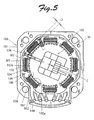
- JP2008-206393A discloses a stator for rotary electric machine that is used for a compact rotary electric machine, which includes a stator core 103 having an annular yoke 101 and a plurality of magnetic pole portions 102 projecting toward a centerline C of the annular yoke 101, a plurality of winding portions 104 formed of a winding conductor wound around the plurality of magnetic pole portions 102, and a slot insulator 105 that is formed of an insulating resin and attached to the stator core 103 for insulating the stator core 103 from the winding portions 104, as shown in FIG. 5 .
- a winding machine M for winding the winding conductor is also illustrated in FIG. 5 .
- a connecting wire hook 106 for engaging with a connecting wire formed of a part of the winding conductor is formed on one end portion of the slot insulator 105.
- the connecting wire hook 106 is formed in a portion that faces a slot opening space 107, which is a space between adjoining two of magnetic pole pieces 102a covered with the slot insulator 105.
- the connecting wire hook 106 located within an extended slot space 109, which is defined by extending a slot space 108, where the winding portion 104 is located, toward the connecting wire hook 106 of the slot insulator 105.
- the connecting wire hook 106 is formed within the extended slot space 109, which is defined by extending the slot space 108 in a direction perpendicular to the surface of the paper of FIG. 5 . It becomes difficult to dispose the connecting wire hook 106 on an end face of the yoke because the diameter of the slot insulator becomes also small as the diameter of the stator core is small in a smaller rotary electric machine. Thus, the connecting wire hook 106 needs to be disposed within the extended slot space 109.
- a winding conductor is led out from a leading end M2 of a nozzle M1 of the winding machine M and wound around the plurality of magnetic pole portions 102. More specifically, the leading end M2 of the nozzle M1 is positioned in the vicinity of the connecting wire hook 106 at first. Subsequently, the nozzle M1 performs what is called a "box movement" which is the combination of an up/down motion in an extending direction of the centerline C and an oscillating motion in the circumferential direction of the annular yoke 101 so that the leading end M2 of the nozzle M1 repeatedly turns around the magnetic pole portion 102. In this manner, the winding conductor is led out from the leading end M2 of the nozzle M1 and wound around the plurality of magnetic pole portions 102.
- the connecting wire hook 106 is disposed at the slot insulator 105 within the extended slot space 109
- the presence of the connecting wire hook 106 restricts an operative range of the nozzle M1 when a winding conductor led out from the leading end M2 of the nozzle M1 of the winding machine M is wound around the plurality of magnetic pole portions 102.
- An object of the present invention is to provide a stator for rotary electric machine in which a space factor of a winding portion may be increased even if a connecting wire hook is disposed within an extended slot space (a first extended space).
- a stator for rotary electric machine comprises a stator core, a plurality of winding portions and a slot insulator formed of an insulating resin.
- the stator core includes an annular yoke and a plurality of magnetic pole portions that are disposed at an inner peripheral portion of the annular yoke at intervals in a circumferential direction of the annular yoke.
- the plurality of magnetic pole portions each project toward a centerline of the annular yoke, and have one end integrally formed with the annular yoke.
- the magnetic pole portions each include a pole column and a magnetic pole piece having a magnetic surface.
- the pole column has one end integrally formed with the annular yoke and the other end on which the magnetic pole piece is integrally disposed.
- the plurality of winding portions are formed of winding conductors wound around the plurality of magnetic pole portions of the stator core.
- the slot insulator formed of an insulating resin is attached to the stator core for electrically insulating the stator core from the winding portions.
- the slot insulator is configured from a pair of divided parts so as to sandwich the stator core from both ends thereof.
- the slot insulator integrally includes, at one end portion thereof, connecting wire hooks capable of engaging with connecting wires formed of a part of the winding conductor extending from each of the winding portions.
- the one end portion of the slot insulator is located in one direction where the centerline of the annular yoke extends.
- each of the connecting wire hooks is located at least partially within a first extended space (an extended slot space) which is defined by extending in the one direction a slot space where the winding portion is located.
- the location of the connecting wire hook is determined such that, assuming that a second extended space (an extended virtual space) is defined by extending toward the yoke a slot opening space formed between adjacent two of the magnetic pole pieces covered with the slot insulator, and a third extended space (an extended portion of the extended virtual space) is defined by extending the second extended space in the one direction where the centerline of the annular yoke extends,
- the connecting wire hook may not be located within the third extended space.
- the connecting wire hook in the first extended space is positioned according to the embodiment of the present invention, the connecting wire hook is not disposed in the third extended space.
- the leading end of the nozzle of a winding machine may advance far and reach a portion of the slot insulator facing the slot opening space (namely, a portion conventionally blocked by the connecting wire hook) at the time of starting the winding operation of the winding conductor.
- the winding conductor may be wound around the magnetic pole portion at an end portion (base portion) of the pole column thereof close to or near the annular yoke.
- the nozzle of the winding machine may reach a deepest portion of the slot (a position near the annular yoke) even if the connecting wire hook is disposed within the first extended space.
- the space factor of the winding portion may be increased.
- two of the connecting wire hooks may be disposed in pairs in the first extended space to sandwich the third extended space therebetween.
- the connecting wire hook may be disposed in the vicinity of a course-changing point of the nozzle of the winding machine, and thus the winding conductor may readily and positively be engaged with the connecting wire hook.
- a nozzle receiving groove, along which the leading end of the nozzle passes may be formed in a wall portion of the slot insulator that covers the inner peripheral portion of the annular yoke in an area across the second extended space so as to be opened toward the slot space and also toward the one direction and a direction opposite to the one direction.
- the leading end of the nozzle of the winding machine may advance far and reach the nozzle receiving groove at the time of starting the winding operation of the winding conductor, thereby moving farther into the slot (toward the yoke).
- FIG. 1 is a plan view of a stator for rotary electric machine (stator for rotary motor) according to an embodiment of the present invention.
- FIG. 2 is a cross sectional view of FIG. 1 taken along line II-II.
- FIG. 3 is a plan view of the stator for rotary electric machine of FIG. 1 , illustrating that a winding conductor is wound around a magnetic pole portion.
- FIG. 4 is a cross sectional view of FIG. 3 taken along line IV-IV.
- a winding machine M is also illustrated in FIG. 3 .
- the stator for rotary electric machine includes a stator core 1, eight winding portions 3 of one or more phases (two phases in this embodiment, and a slot insulator 5.
- the stator core 1 is configured such that an annular yoke 7 includes eight magnetic pole portions 9 disposed at an inner peripheral portion of the annular yoke at intervals in a circumferential direction.
- the stator core 1 is formed by stacking a plurality of steel sheets of an identical shape in a direction where a centerline C of the annular yoke 7 extends. As shown in FIG.
- the eight magnetic pole portions 9 each include a pole column 9a projecting toward the centerline C of the annular yoke 7, and a magnetic pole piece 9c having a magnetic surface 9b.
- the pole column 9a has one end integrally formed with the annular yoke 7 and the other end on which the magnetic pole piece 9c is integrally disposed.
- the winding portion 3 ( FIG. 1 ) is formed of a winding conductor wound around each of the eight magnetic pole portions 9.
- a slot insulator 5 formed of an insulating resin is attached to the stator core 1 for electrically insulating the stator core 1 from the winding portion 3.
- the slot insulator 5 is formed of a pair of insulator divided parts 15 and 17 that are fitted with the stator core 1 from both sides thereof in an extending direction of the centerline C of the yoke 7.
- the insulator divided body 15 located in the upper side of FIG. 4 is formed of a synthetic resin, and integrally includes a base portion 19 covering the inner peripheral portion of the annular yoke 7, eight bobbin portions 21 each covering a surface of the magnetic pole portion 9 except for the magnetic pole surface 9b, and a holder attachment portion 23 ( FIG. 3 ).
- Configuration of the insulator divided body 17 of the pair, which is located in the lower side of FIG. 4 is fundamentally the same as that of the insulator divided body 15 except that it includes neither the holder attachment portion 23 nor a connecting wire hook 35 to be described later.
- a slot space 25, where the winding portion 3 is located is defined, being surrounded by the annular yoke 7 and adjoining two of the magnetic pole portions 9 that are covered with the slot insulator 5.
- a slot opening space 27 is defined between adjoining two of the magnetic pole pieces 9c covered with the slot insulator 5.
- a second extended space 29 an area sandwiched by dotted lines in FIG. 3
- a third extended space 31 an area surrounded by dashed dotted lines in FIG.
- a nozzle receiving groove 33 is formed in the base portion 19 of the pair of insulator divided bodies 15 and 17 in an area across the second extended space 29 so as to be opened toward the slot space 25 and also toward the one direction where the centerline C extends and a direction opposite to the one direction.
- the insulator divided body 15 integrally includes at one end portion thereof twelve connecting wire hooks 35 extending from the base portion 19 in the one direction where the centerline of the annular yoke 7 extends.
- the one end portion of the insulator divided body 15 is located in the one direction.
- a connecting wire formed of a part of the winding conductor extending from the winding portion 3 is engaging with the connecting wire hook 35, which is disposed in pair within the six slot spaces 25 except for two slot spaces 25 in the vicinity of the holder attachment portion 23.
- the connecting wire hook 35 is not disposed in the two slot spaces adjoining the holder attachment portion 23.
- the connecting wire hook need not to be provided for all the slot spaces, and it may be sufficient to dispose the connecting wire hook only in locations where the connecting wire needs to be hooked.
- Two of the connecting wire hooks 35 are disposed in pairs in a first extended space 37 which is defined by extending the slot space 25 in the one direction where the centerline C extends.
- two of the connecting wire hooks 35 in pairs are located to sandwich the third extended space31 on both sides of the nozzle receiving groove 33.
- the connecting wire hooks 35 in pairs within the first extended space 37 are not disposed in the third extended space.
- the connecting wire hooks 35 are disposed to keep away from a central portion, as viewed in the circumferential direction of the annular yoke 7, of the first extended space 37 (namely, an area corresponding to the third extended space 31.
- the leading end M2 of the nozzle M1 of a winding machine M is placed in the nozzle receiving groove 33.
- the nozzle M1 performs what is called a "box movement" which is the combination of an up/down motion in an extending direction of the centerline C and an oscillating motion in the circumferential direction of the annular yoke 7 so that the leading end M2 of the nozzle M1 repeatedly turns around the magnetic pole portion 9.
- the winding conductor is led out from the leading end M2 of the nozzle M1 and wound around the pole column 9a covered with the slot insulator 5.
- the connecting wire hook 35 is not located in the third extended space 31.
- the leading end M2 of the nozzle M1 of the winding machine M may advance far and reach a portion of the slot insulator 5 that faces the slot opening space 27 (namely, a portion conventionally blocked by the connecting wire hook) at the time of starting the winding operation of the winding conductor.
- a length L1 shown in FIG. 3 by which the leading end M2 of the nozzle M1 reciprocates within the slot space 25 is longer than a length L2, shown in FIG. 5 , by which the leading end M2 of the nozzle M1 reciprocates within a slot space 108.
- the winding conductor may be wound around an end portion 9d of the magnetic pole portion 9, located on a side of the yoke (see the lower left portion of FIG. 1 ), thereby forming the winding portion 3.
- the winding conductor is not wound around an end portion 102 of the winding portion 104, located on the side of the yoke.
- the space factor of the winding portion is more increased than ever in a situation where the connecting wire hook 35 is positioned within the first extended space 37.
- connecting wire hooks 35 are disposed in one slot space 25 in the above-mentioned embodiment.
- a single connecting wire hook 35 may be disposed in one slot space 25 according to the present invention.
- the connecting wire hook 35 may preferably be located in the vicinity of the nozzle receiving groove 33, it may be located in the vicinity of the base portion of the pole column 9a of the magnetic pole portion 9 as long as the space factor can be increased more than ever.
- the connecting wire hook is not located in the third extended space, which is defined by extending in the one direction the second extended space which is defined by extending toward the yoke the slot opening space that is formed between adjoining two of the magnetic pole pieces covered with the slot insulator.
- the leading end of the nozzle of the winding machine may advance far and reach a portion of the slot insulator that faces the slot opening space (an area which is blocked by the connecting wire hook in conventional arts).
- a winding conductor may be wound around the magnetic pole portion from a base portion of the pole column, and the space factor of the winding portion may be increased in a situation where the connecting wire hook is located in the first extended space.
Landscapes
- Engineering & Computer Science (AREA)
- Power Engineering (AREA)
- Manufacturing & Machinery (AREA)
- Insulation, Fastening Of Motor, Generator Windings (AREA)
Applications Claiming Priority (1)
| Application Number | Priority Date | Filing Date | Title |
|---|---|---|---|
| JP2009052386A JP5605997B2 (ja) | 2009-03-05 | 2009-03-05 | 回転電機用ステータ |
Publications (3)
| Publication Number | Publication Date |
|---|---|
| EP2226918A2 true EP2226918A2 (de) | 2010-09-08 |
| EP2226918A3 EP2226918A3 (de) | 2016-07-06 |
| EP2226918B1 EP2226918B1 (de) | 2018-08-01 |
Family
ID=42077729
Family Applications (1)
| Application Number | Title | Priority Date | Filing Date |
|---|---|---|---|
| EP10155289.1A Active EP2226918B1 (de) | 2009-03-05 | 2010-03-03 | Stator für eine elektrische Drehmaschine |
Country Status (5)
| Country | Link |
|---|---|
| US (1) | US8063523B2 (de) |
| EP (1) | EP2226918B1 (de) |
| JP (1) | JP5605997B2 (de) |
| KR (1) | KR101665996B1 (de) |
| CN (1) | CN101860095B (de) |
Cited By (1)
| Publication number | Priority date | Publication date | Assignee | Title |
|---|---|---|---|---|
| WO2012175476A3 (de) * | 2011-06-23 | 2013-08-01 | Siemens Aktiengesellschaft | Wickelkopfträger für einen stator einer elektrischen maschine |
Families Citing this family (1)
| Publication number | Priority date | Publication date | Assignee | Title |
|---|---|---|---|---|
| JP5414918B1 (ja) * | 2013-01-31 | 2014-02-12 | 日本航空電子工業株式会社 | レゾルバのステータ及びレゾルバ |
Citations (1)
| Publication number | Priority date | Publication date | Assignee | Title |
|---|---|---|---|---|
| JP2008206393A (ja) | 2008-03-12 | 2008-09-04 | Sanyo Denki Co Ltd | 回転電機 |
Family Cites Families (18)
| Publication number | Priority date | Publication date | Assignee | Title |
|---|---|---|---|---|
| US5194775A (en) * | 1992-03-09 | 1993-03-16 | Morrill Electric, Inc. | Electric motor stator tabs |
| JPH05308768A (ja) * | 1992-04-28 | 1993-11-19 | Minebea Co Ltd | ステッピングモータ用ステータヨーク |
| JP3190511B2 (ja) * | 1994-03-02 | 2001-07-23 | 三菱電機株式会社 | 回転電動機およびその製造方法 |
| DE19740938A1 (de) * | 1997-09-17 | 1999-03-18 | Trw Fahrzeugelektrik | Stator für einen Elektromotor, insbesondere bürstenlosen Gleichstrommotor |
| JPH11206057A (ja) * | 1998-01-16 | 1999-07-30 | Oriental Motor Co Ltd | モータのステータコア用インシュレータ構造 |
| US6941638B2 (en) * | 2002-07-11 | 2005-09-13 | Emerson Electric Co. | Interconnecting method for segmented stator electric machines |
| EP1505711B1 (de) * | 2003-08-02 | 2010-05-19 | ebm-papst St. Georgen GmbH & Co. KG | Elektromotor |
| JP4457612B2 (ja) * | 2003-09-01 | 2010-04-28 | ダイキン工業株式会社 | 圧縮機、電動機及びその固定子 |
| DE50313509D1 (de) * | 2003-10-22 | 2011-04-14 | Brose Fahrzeugteile | Verschaltungseinheit für einen Stator eines Elektromotors |
| JP4615910B2 (ja) * | 2004-06-29 | 2011-01-19 | サムソン エレクトロ−メカニックス カンパニーリミテッド. | ステータコア、モータおよび記録媒体駆動装置 |
| US7513029B2 (en) * | 2005-02-02 | 2009-04-07 | Black & Decker Inc. | Tool for manufacturing coils for dynamoelectric machines and method therefor |
| CN201204524Y (zh) * | 2005-02-02 | 2009-03-04 | 布莱克和戴克公司 | 用于形成电动机械的线圈的线圈缠绕工具 |
| JP4749056B2 (ja) * | 2005-06-28 | 2011-08-17 | オリエンタルモーター株式会社 | モータのステータ構造 |
| JP4137101B2 (ja) * | 2005-08-17 | 2008-08-20 | 山洋電気株式会社 | 回転電機 |
| JP2007053896A (ja) * | 2005-08-17 | 2007-03-01 | Minebea Co Ltd | ステータユニット及びその製造方法 |
| JP2007124733A (ja) * | 2005-10-25 | 2007-05-17 | Matsushita Electric Ind Co Ltd | スピンドルモータ |
| JP3946240B1 (ja) * | 2006-07-20 | 2007-07-18 | 山洋電気株式会社 | 回転電機用ステータ |
| EP2082472B1 (de) * | 2006-10-14 | 2012-10-10 | ebm-papst St. Georgen GmbH & Co. KG | Elektromotor |
-
2009
- 2009-03-05 JP JP2009052386A patent/JP5605997B2/ja active Active
-
2010
- 2010-03-03 US US12/716,543 patent/US8063523B2/en active Active
- 2010-03-03 EP EP10155289.1A patent/EP2226918B1/de active Active
- 2010-03-03 KR KR1020100018856A patent/KR101665996B1/ko active Active
- 2010-03-05 CN CN201010190555.9A patent/CN101860095B/zh active Active
Patent Citations (1)
| Publication number | Priority date | Publication date | Assignee | Title |
|---|---|---|---|---|
| JP2008206393A (ja) | 2008-03-12 | 2008-09-04 | Sanyo Denki Co Ltd | 回転電機 |
Cited By (1)
| Publication number | Priority date | Publication date | Assignee | Title |
|---|---|---|---|---|
| WO2012175476A3 (de) * | 2011-06-23 | 2013-08-01 | Siemens Aktiengesellschaft | Wickelkopfträger für einen stator einer elektrischen maschine |
Also Published As
| Publication number | Publication date |
|---|---|
| JP2010207033A (ja) | 2010-09-16 |
| KR20100100638A (ko) | 2010-09-15 |
| US20100225185A1 (en) | 2010-09-09 |
| EP2226918A3 (de) | 2016-07-06 |
| CN101860095A (zh) | 2010-10-13 |
| JP5605997B2 (ja) | 2014-10-15 |
| CN101860095B (zh) | 2014-05-28 |
| KR101665996B1 (ko) | 2016-10-13 |
| US8063523B2 (en) | 2011-11-22 |
| EP2226918B1 (de) | 2018-08-01 |
Similar Documents
| Publication | Publication Date | Title |
|---|---|---|
| US10090723B2 (en) | Stator and manufacturing method of stator | |
| EP2833521A1 (de) | Stator | |
| JP6075126B2 (ja) | コモンモードチョークコイル | |
| EP3159903B1 (de) | Resonanter transformator mit hoher stromdichte | |
| US7763999B2 (en) | Stator for rotary electric machines | |
| JP7023864B2 (ja) | モータ | |
| EP2226918B1 (de) | Stator für eine elektrische Drehmaschine | |
| EP3208574B1 (de) | Drehmelderstator | |
| CN209725391U (zh) | 电磁阀的螺线管 | |
| JP5873262B2 (ja) | アウターロータ型モータ | |
| JP2012182103A (ja) | ボンダーキャップ | |
| US7188401B2 (en) | Motor case | |
| KR102666281B1 (ko) | 전기 모터를 위한 고정자 | |
| JP7063205B2 (ja) | 固定子巻線構造 | |
| JP2008109746A (ja) | ステータ | |
| WO2003073446A1 (en) | Transformer | |
| JP2003009447A (ja) | 電動機の固定子 | |
| JP2020162300A (ja) | 回転電機 | |
| CN106877542A (zh) | 定子及具有其的电机 | |
| US20150228404A1 (en) | Coil Wire Support Element, Manufacturing Method Thereof, and Inductive Power Transfer Coupler Incorprationg The Same | |
| JP4918279B2 (ja) | 回転電機のステータ構造 | |
| JP6755446B2 (ja) | レゾルバステータ構造 | |
| JP5907831B2 (ja) | 電機子のインシュレータおよび電機子 | |
| JP2017195568A (ja) | ノイズフィルタ付き導電路 | |
| JP6541542B2 (ja) | 巻線部品 |
Legal Events
| Date | Code | Title | Description |
|---|---|---|---|
| PUAI | Public reference made under article 153(3) epc to a published international application that has entered the european phase |
Free format text: ORIGINAL CODE: 0009012 |
|
| AK | Designated contracting states |
Kind code of ref document: A2 Designated state(s): AT BE BG CH CY CZ DE DK EE ES FI FR GB GR HR HU IE IS IT LI LT LU LV MC MK MT NL NO PL PT RO SE SI SK SM TR |
|
| AX | Request for extension of the european patent |
Extension state: AL BA ME RS |
|
| PUAL | Search report despatched |
Free format text: ORIGINAL CODE: 0009013 |
|
| AK | Designated contracting states |
Kind code of ref document: A3 Designated state(s): AT BE BG CH CY CZ DE DK EE ES FI FR GB GR HR HU IE IS IT LI LT LU LV MC MK MT NL NO PL PT RO SE SI SK SM TR |
|
| AX | Request for extension of the european patent |
Extension state: AL BA ME RS |
|
| RIC1 | Information provided on ipc code assigned before grant |
Ipc: H02K 15/095 20060101ALI20160531BHEP Ipc: H02K 3/52 20060101AFI20160531BHEP |
|
| STAA | Information on the status of an ep patent application or granted ep patent |
Free format text: STATUS: REQUEST FOR EXAMINATION WAS MADE |
|
| 17P | Request for examination filed |
Effective date: 20161223 |
|
| RBV | Designated contracting states (corrected) |
Designated state(s): AT BE BG CH CY CZ DE DK EE ES FI FR GB GR HR HU IE IS IT LI LT LU LV MC MK MT NL NO PL PT RO SE SI SK SM TR |
|
| GRAP | Despatch of communication of intention to grant a patent |
Free format text: ORIGINAL CODE: EPIDOSNIGR1 |
|
| STAA | Information on the status of an ep patent application or granted ep patent |
Free format text: STATUS: GRANT OF PATENT IS INTENDED |
|
| INTG | Intention to grant announced |
Effective date: 20180228 |
|
| GRAS | Grant fee paid |
Free format text: ORIGINAL CODE: EPIDOSNIGR3 |
|
| GRAA | (expected) grant |
Free format text: ORIGINAL CODE: 0009210 |
|
| STAA | Information on the status of an ep patent application or granted ep patent |
Free format text: STATUS: THE PATENT HAS BEEN GRANTED |
|
| AK | Designated contracting states |
Kind code of ref document: B1 Designated state(s): AT BE BG CH CY CZ DE DK EE ES FI FR GB GR HR HU IE IS IT LI LT LU LV MC MK MT NL NO PL PT RO SE SI SK SM TR |
|
| REG | Reference to a national code |
Ref country code: GB Ref legal event code: FG4D |
|
| REG | Reference to a national code |
Ref country code: CH Ref legal event code: EP Ref country code: AT Ref legal event code: REF Ref document number: 1025491 Country of ref document: AT Kind code of ref document: T Effective date: 20180815 |
|
| REG | Reference to a national code |
Ref country code: IE Ref legal event code: FG4D |
|
| REG | Reference to a national code |
Ref country code: DE Ref legal event code: R096 Ref document number: 602010052285 Country of ref document: DE |
|
| REG | Reference to a national code |
Ref country code: NL Ref legal event code: MP Effective date: 20180801 |
|
| REG | Reference to a national code |
Ref country code: LT Ref legal event code: MG4D |
|
| REG | Reference to a national code |
Ref country code: AT Ref legal event code: MK05 Ref document number: 1025491 Country of ref document: AT Kind code of ref document: T Effective date: 20180801 |
|
| PG25 | Lapsed in a contracting state [announced via postgrant information from national office to epo] |
Ref country code: NO Free format text: LAPSE BECAUSE OF FAILURE TO SUBMIT A TRANSLATION OF THE DESCRIPTION OR TO PAY THE FEE WITHIN THE PRESCRIBED TIME-LIMIT Effective date: 20181101 Ref country code: AT Free format text: LAPSE BECAUSE OF FAILURE TO SUBMIT A TRANSLATION OF THE DESCRIPTION OR TO PAY THE FEE WITHIN THE PRESCRIBED TIME-LIMIT Effective date: 20180801 Ref country code: IS Free format text: LAPSE BECAUSE OF FAILURE TO SUBMIT A TRANSLATION OF THE DESCRIPTION OR TO PAY THE FEE WITHIN THE PRESCRIBED TIME-LIMIT Effective date: 20181201 Ref country code: FI Free format text: LAPSE BECAUSE OF FAILURE TO SUBMIT A TRANSLATION OF THE DESCRIPTION OR TO PAY THE FEE WITHIN THE PRESCRIBED TIME-LIMIT Effective date: 20180801 Ref country code: GR Free format text: LAPSE BECAUSE OF FAILURE TO SUBMIT A TRANSLATION OF THE DESCRIPTION OR TO PAY THE FEE WITHIN THE PRESCRIBED TIME-LIMIT Effective date: 20181102 Ref country code: LT Free format text: LAPSE BECAUSE OF FAILURE TO SUBMIT A TRANSLATION OF THE DESCRIPTION OR TO PAY THE FEE WITHIN THE PRESCRIBED TIME-LIMIT Effective date: 20180801 Ref country code: PL Free format text: LAPSE BECAUSE OF FAILURE TO SUBMIT A TRANSLATION OF THE DESCRIPTION OR TO PAY THE FEE WITHIN THE PRESCRIBED TIME-LIMIT Effective date: 20180801 Ref country code: SE Free format text: LAPSE BECAUSE OF FAILURE TO SUBMIT A TRANSLATION OF THE DESCRIPTION OR TO PAY THE FEE WITHIN THE PRESCRIBED TIME-LIMIT Effective date: 20180801 Ref country code: BG Free format text: LAPSE BECAUSE OF FAILURE TO SUBMIT A TRANSLATION OF THE DESCRIPTION OR TO PAY THE FEE WITHIN THE PRESCRIBED TIME-LIMIT Effective date: 20181101 Ref country code: NL Free format text: LAPSE BECAUSE OF FAILURE TO SUBMIT A TRANSLATION OF THE DESCRIPTION OR TO PAY THE FEE WITHIN THE PRESCRIBED TIME-LIMIT Effective date: 20180801 |
|
| PG25 | Lapsed in a contracting state [announced via postgrant information from national office to epo] |
Ref country code: LV Free format text: LAPSE BECAUSE OF FAILURE TO SUBMIT A TRANSLATION OF THE DESCRIPTION OR TO PAY THE FEE WITHIN THE PRESCRIBED TIME-LIMIT Effective date: 20180801 Ref country code: HR Free format text: LAPSE BECAUSE OF FAILURE TO SUBMIT A TRANSLATION OF THE DESCRIPTION OR TO PAY THE FEE WITHIN THE PRESCRIBED TIME-LIMIT Effective date: 20180801 Ref country code: ES Free format text: LAPSE BECAUSE OF FAILURE TO SUBMIT A TRANSLATION OF THE DESCRIPTION OR TO PAY THE FEE WITHIN THE PRESCRIBED TIME-LIMIT Effective date: 20180801 |
|
| PG25 | Lapsed in a contracting state [announced via postgrant information from national office to epo] |
Ref country code: CZ Free format text: LAPSE BECAUSE OF FAILURE TO SUBMIT A TRANSLATION OF THE DESCRIPTION OR TO PAY THE FEE WITHIN THE PRESCRIBED TIME-LIMIT Effective date: 20180801 Ref country code: RO Free format text: LAPSE BECAUSE OF FAILURE TO SUBMIT A TRANSLATION OF THE DESCRIPTION OR TO PAY THE FEE WITHIN THE PRESCRIBED TIME-LIMIT Effective date: 20180801 Ref country code: EE Free format text: LAPSE BECAUSE OF FAILURE TO SUBMIT A TRANSLATION OF THE DESCRIPTION OR TO PAY THE FEE WITHIN THE PRESCRIBED TIME-LIMIT Effective date: 20180801 Ref country code: IT Free format text: LAPSE BECAUSE OF FAILURE TO SUBMIT A TRANSLATION OF THE DESCRIPTION OR TO PAY THE FEE WITHIN THE PRESCRIBED TIME-LIMIT Effective date: 20180801 |
|
| REG | Reference to a national code |
Ref country code: DE Ref legal event code: R097 Ref document number: 602010052285 Country of ref document: DE |
|
| PG25 | Lapsed in a contracting state [announced via postgrant information from national office to epo] |
Ref country code: SK Free format text: LAPSE BECAUSE OF FAILURE TO SUBMIT A TRANSLATION OF THE DESCRIPTION OR TO PAY THE FEE WITHIN THE PRESCRIBED TIME-LIMIT Effective date: 20180801 Ref country code: DK Free format text: LAPSE BECAUSE OF FAILURE TO SUBMIT A TRANSLATION OF THE DESCRIPTION OR TO PAY THE FEE WITHIN THE PRESCRIBED TIME-LIMIT Effective date: 20180801 Ref country code: SM Free format text: LAPSE BECAUSE OF FAILURE TO SUBMIT A TRANSLATION OF THE DESCRIPTION OR TO PAY THE FEE WITHIN THE PRESCRIBED TIME-LIMIT Effective date: 20180801 |
|
| PLBE | No opposition filed within time limit |
Free format text: ORIGINAL CODE: 0009261 |
|
| STAA | Information on the status of an ep patent application or granted ep patent |
Free format text: STATUS: NO OPPOSITION FILED WITHIN TIME LIMIT |
|
| 26N | No opposition filed |
Effective date: 20190503 |
|
| PG25 | Lapsed in a contracting state [announced via postgrant information from national office to epo] |
Ref country code: SI Free format text: LAPSE BECAUSE OF FAILURE TO SUBMIT A TRANSLATION OF THE DESCRIPTION OR TO PAY THE FEE WITHIN THE PRESCRIBED TIME-LIMIT Effective date: 20180801 |
|
| PG25 | Lapsed in a contracting state [announced via postgrant information from national office to epo] |
Ref country code: MC Free format text: LAPSE BECAUSE OF FAILURE TO SUBMIT A TRANSLATION OF THE DESCRIPTION OR TO PAY THE FEE WITHIN THE PRESCRIBED TIME-LIMIT Effective date: 20180801 |
|
| REG | Reference to a national code |
Ref country code: CH Ref legal event code: PL |
|
| PG25 | Lapsed in a contracting state [announced via postgrant information from national office to epo] |
Ref country code: LU Free format text: LAPSE BECAUSE OF NON-PAYMENT OF DUE FEES Effective date: 20190303 |
|
| REG | Reference to a national code |
Ref country code: BE Ref legal event code: MM Effective date: 20190331 |
|
| PG25 | Lapsed in a contracting state [announced via postgrant information from national office to epo] |
Ref country code: CH Free format text: LAPSE BECAUSE OF NON-PAYMENT OF DUE FEES Effective date: 20190331 Ref country code: LI Free format text: LAPSE BECAUSE OF NON-PAYMENT OF DUE FEES Effective date: 20190331 Ref country code: IE Free format text: LAPSE BECAUSE OF NON-PAYMENT OF DUE FEES Effective date: 20190303 |
|
| PG25 | Lapsed in a contracting state [announced via postgrant information from national office to epo] |
Ref country code: BE Free format text: LAPSE BECAUSE OF NON-PAYMENT OF DUE FEES Effective date: 20190331 |
|
| PG25 | Lapsed in a contracting state [announced via postgrant information from national office to epo] |
Ref country code: TR Free format text: LAPSE BECAUSE OF FAILURE TO SUBMIT A TRANSLATION OF THE DESCRIPTION OR TO PAY THE FEE WITHIN THE PRESCRIBED TIME-LIMIT Effective date: 20180801 |
|
| PG25 | Lapsed in a contracting state [announced via postgrant information from national office to epo] |
Ref country code: PT Free format text: LAPSE BECAUSE OF FAILURE TO SUBMIT A TRANSLATION OF THE DESCRIPTION OR TO PAY THE FEE WITHIN THE PRESCRIBED TIME-LIMIT Effective date: 20181201 Ref country code: MT Free format text: LAPSE BECAUSE OF NON-PAYMENT OF DUE FEES Effective date: 20190303 |
|
| PG25 | Lapsed in a contracting state [announced via postgrant information from national office to epo] |
Ref country code: CY Free format text: LAPSE BECAUSE OF FAILURE TO SUBMIT A TRANSLATION OF THE DESCRIPTION OR TO PAY THE FEE WITHIN THE PRESCRIBED TIME-LIMIT Effective date: 20180801 |
|
| PG25 | Lapsed in a contracting state [announced via postgrant information from national office to epo] |
Ref country code: HU Free format text: LAPSE BECAUSE OF FAILURE TO SUBMIT A TRANSLATION OF THE DESCRIPTION OR TO PAY THE FEE WITHIN THE PRESCRIBED TIME-LIMIT; INVALID AB INITIO Effective date: 20100303 |
|
| PG25 | Lapsed in a contracting state [announced via postgrant information from national office to epo] |
Ref country code: MK Free format text: LAPSE BECAUSE OF FAILURE TO SUBMIT A TRANSLATION OF THE DESCRIPTION OR TO PAY THE FEE WITHIN THE PRESCRIBED TIME-LIMIT Effective date: 20180801 |
|
| PGFP | Annual fee paid to national office [announced via postgrant information from national office to epo] |
Ref country code: GB Payment date: 20240320 Year of fee payment: 15 |
|
| GBPC | Gb: european patent ceased through non-payment of renewal fee |
Effective date: 20250303 |
|
| PG25 | Lapsed in a contracting state [announced via postgrant information from national office to epo] |
Ref country code: GB Free format text: LAPSE BECAUSE OF NON-PAYMENT OF DUE FEES Effective date: 20250303 |
|
| PGFP | Annual fee paid to national office [announced via postgrant information from national office to epo] |
Ref country code: DE Payment date: 20260319 Year of fee payment: 17 |
|
| PGFP | Annual fee paid to national office [announced via postgrant information from national office to epo] |
Ref country code: FR Payment date: 20260320 Year of fee payment: 17 |