EP2226448A2 - Lichtschacht-Montagedämmplatte - Google Patents
Lichtschacht-Montagedämmplatte Download PDFInfo
- Publication number
- EP2226448A2 EP2226448A2 EP10002118A EP10002118A EP2226448A2 EP 2226448 A2 EP2226448 A2 EP 2226448A2 EP 10002118 A EP10002118 A EP 10002118A EP 10002118 A EP10002118 A EP 10002118A EP 2226448 A2 EP2226448 A2 EP 2226448A2
- Authority
- EP
- European Patent Office
- Prior art keywords
- insulation
- light shaft
- building wall
- attachment points
- dowel
- Prior art date
- Legal status (The legal status is an assumption and is not a legal conclusion. Google has not performed a legal analysis and makes no representation as to the accuracy of the status listed.)
- Granted
Links
- 238000009413 insulation Methods 0.000 claims abstract description 95
- 238000003475 lamination Methods 0.000 claims abstract description 14
- 238000000034 method Methods 0.000 claims abstract description 10
- 239000012774 insulation material Substances 0.000 claims abstract description 9
- 239000011810 insulating material Substances 0.000 claims description 21
- 238000010079 rubber tapping Methods 0.000 claims description 8
- 239000000463 material Substances 0.000 description 5
- 239000011521 glass Substances 0.000 description 4
- 239000006260 foam Substances 0.000 description 3
- 229910052500 inorganic mineral Inorganic materials 0.000 description 3
- 238000009434 installation Methods 0.000 description 3
- 239000011707 mineral Substances 0.000 description 3
- 239000004033 plastic Substances 0.000 description 3
- 239000004568 cement Substances 0.000 description 2
- 239000000835 fiber Substances 0.000 description 2
- 239000008187 granular material Substances 0.000 description 2
- 230000005855 radiation Effects 0.000 description 2
- XLYOFNOQVPJJNP-UHFFFAOYSA-N water Substances O XLYOFNOQVPJJNP-UHFFFAOYSA-N 0.000 description 2
- 238000006424 Flood reaction Methods 0.000 description 1
- 241001074085 Scophthalmus aquosus Species 0.000 description 1
- 239000004795 extruded polystyrene foam Substances 0.000 description 1
- 239000011494 foam glass Substances 0.000 description 1
- 239000006261 foam material Substances 0.000 description 1
- 239000011888 foil Substances 0.000 description 1
- 239000000203 mixture Substances 0.000 description 1
- 239000003973 paint Substances 0.000 description 1
- 239000011505 plaster Substances 0.000 description 1
- 239000002985 plastic film Substances 0.000 description 1
- 239000000565 sealant Substances 0.000 description 1
- 239000003566 sealing material Substances 0.000 description 1
- 239000002699 waste material Substances 0.000 description 1
Images


Classifications
-
- E—FIXED CONSTRUCTIONS
- E04—BUILDING
- E04F—FINISHING WORK ON BUILDINGS, e.g. STAIRS, FLOORS
- E04F17/00—Vertical ducts; Channels, e.g. for drainage
- E04F17/06—Light shafts, e.g. for cellars
-
- E—FIXED CONSTRUCTIONS
- E04—BUILDING
- E04B—GENERAL BUILDING CONSTRUCTIONS; WALLS, e.g. PARTITIONS; ROOFS; FLOORS; CEILINGS; INSULATION OR OTHER PROTECTION OF BUILDINGS
- E04B1/00—Constructions in general; Structures which are not restricted either to walls, e.g. partitions, or floors or ceilings or roofs
- E04B1/62—Insulation or other protection; Elements or use of specified material therefor
- E04B1/74—Heat, sound or noise insulation, absorption, or reflection; Other building methods affording favourable thermal or acoustical conditions, e.g. accumulating of heat within walls
- E04B1/76—Heat, sound or noise insulation, absorption, or reflection; Other building methods affording favourable thermal or acoustical conditions, e.g. accumulating of heat within walls specifically with respect to heat only
- E04B1/762—Exterior insulation of exterior walls
- E04B1/7637—Anchoring of separate elements through the lining to the wall
Definitions
- the present invention relates to a thermal insulation for a building wall in the basement area of a house with an insulation which is arranged on the building wall. Furthermore, the present invention relates to a method for mounting a light well on a thermally insulated with a Perimeterdämmung building wall.
- Thermal insulation is becoming more and more important nowadays. It is particularly desirable to insulate the basement area of a house.
- the arrangement of a light shaft which was arranged in the region of openings in the building wall in the basement area, has proven to be very expensive. Partly holes were pre-drilled in the building wall, to which then the light shaft should be attached. However, after arranging the thermal insulation, it was extremely difficult to find these pre-drilled holes.
- Another solution according to the utility model DE 203 03 405 U1 Proposes to provide the insulation in the area of the light shaft in great numbers and to piece it around the light shaft. This form of insulation is extremely expensive. Furthermore, the fortifications represent thermal bridges and the subsequent plastering is very expensive.
- the problem is solved with a thermal insulation for a building wall in the basement area of a house, with an insulation, which is arranged on the building wall, wherein the insulation has attachment points to which a light shaft can be attached.
- the present invention relates to the thermal insulation for a building wall in the basement area of a house with an insulation on the building wall is arranged.
- the insulation is glued to the building wall, but can also be positively and / or non-positively fastened, for example with screws on the basement wall.
- the insulation has attachment points to which a light shaft can be attached.
- the light shaft is therefore attached only to the insulation and not on the building wall itself. It can therefore initially arranged the insulation on the building wall, in particular glued and then the light shaft are mounted on the insulation without having to be drilled in the building wall. As a result, the installation of the light shaft on an insulated basement wall is considerably simplified.
- the insulation carries the light shaft completely.
- the light shaft is not directly connected to the building wall.
- the light shaft is made of a plastic material.
- the light shaft is two-piece, with an upper and a lower part executed.
- the insulation consists of an insulating material whose thickness is particularly preferably at least 80 mm, preferably 100 mm or more.
- the insulating material is a so-called perimeter insulation.
- Perimeter insulation is the thermal insulation of earth-contacting components of buildings and structures on their outside. This can be both the insulation below the floor slab of a building as well as the wall insulation of an embedded in the ground basement exterior wall.
- the insulation must be resistant to water and pressure, therefore preferably closed-cell foam materials, eg. As extruded polystyrene foam boards or foam glass plates used.
- the insulation material is applied outside the waterproof layer (bituminous paint or plastic foil).
- the insulating material is preferably provided in the form of plates. These insulation boards are preferably glued to them Do not move if the backfill of the pit is set or if the light shaft is attached to the insulation.
- recycled materials such as glass foam granules and glass foam panels and / or mineral materials can be used as Perimeterdämmung.
- Glass foam granules are made, for example, from pure waste glass. Also conceivable is a combination of mineral and plastic materials as a mixture and / or as a multi-layer insulation.
- the insulation preferably has a lamination, in particular on the side of the insulating material facing away from the building wall.
- This lamination protects the insulating material in particular against mechanical influences and weathering, UV radiation, thus represents a substitute for a plaster and is used in the present case very particularly preferably as a facility for the light shaft and / or as a guide and / or support for a fastener , which is arranged in the insulation, in particular in the thermal insulation material.
- the lamination may be, for example, a sheet of mineral material, in particular fiber cement board or a plastic sheet. The lamination is positively / positively and / or positively connected to the insulation material.
- the attachment points are marked in / on the insulation and / or at least partially prefabricated, for example, predrilled.
- the fastening points are marked on the lining and / or at least partially incorporated therein.
- at least two fastening points are present at a height with which the light shaft can be attached to the insulation on the right and left of an opening in the building wall.
- Very particular preference is given to several attachment points with each other, in particular in a certain grid, very particularly preferably, both right and left of a building wall opening marked and / or at least partially prefabricated.
- a fastening means is at least partially arranged.
- This attachment means preferably does not extend through the entire thickness of the insulation.
- the fastener is not on the Building wall and / or extends into this.
- the fastening means is a dowel, very particularly preferably a self-tapping dowel, which cuts a corresponding opening, in particular in the insulating material.
- the dowel connects positively and / or positively with the insulating material and / or with the lamination.
- the dowel on a collar which rests after its arrangement in the insulation on the insulating material or on the lamination.
- the dowel is screwed into the insulating material.
- the thermal insulation comprises an insert which is inserted between the wall and the window frame and / or the insulation and the window frame.
- the edges of the insulation facing the opening can be protected and / or the thermal insulation according to the invention can be protected against ingress of water behind the insulation, in particular during floods.
- both the interface window frame / insert and the interface insert / insulation is sealed with a sealant.
- Another object of the present invention is therefore a method for mounting a light shaft on a heat-insulated with an insulating building wall, in which the fastening means disposed in the insulation and the light shaft is attached thereto.
- a dowel is placed in the insulation.
- a self-tapping dowel is used, which cuts in particular in the insulating material and thus enters into a positive and / or non-positive connection with the thermal insulation material.
- the dowel is screwed so far into the thermal insulation material until a collar, the on Is located at the end of the anchor, preferably applied to the insulating material or on an existing lamination.
- the dowel does not necessarily have to have a collar
- the light shaft is then fastened by screws to the dowels.
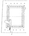
- FIG. 1 shows the thermal insulation according to the invention on which a light shaft is arranged in three views.
- FIG. 2 shows the thermal insulation according to the invention.
- FIG. 3 shows the arrangement of a dowel in the thermal insulation.
- FIG. 4 shows the light shaft attached to the insulation.
- FIG. 1 shows a building wall 1, in the present case, a basement wall, in which a cellar window is provided.
- This basement window has a window frame 2 and a window pane 3.
- the building wall 1 On its outer side, the building wall 1 is provided with an insulation 4, a so-called perimeter insulation 4, the area of the recess 1.1 being recessed.
- This insulation 4 is in the present case of an insulating material 4.3, which is glued to the building wall and from a lining 4.2 made of fiber cement, which is located on the side facing away from the building wall 1 and applied to the insulating material 4.3, preferably glued.
- the insulation is provided plate-shaped.
- the insulation 4 here in particular the lining 4.2, a plurality of attachment points 4.1, which are arranged one above the other in a, preferably vetikalen row each right and left of the window opening.
- the fastening points 4.1 in the present case bores that extend only through the lining, are each arranged at the same height to the right and left of the window.
- the holes to the right and left of the window are at least partially arranged in a certain, the same pitch. This makes it possible to arrange different types of light wells and / or different sizes of light wells in the region of the window opening, without the need for a large installation effort. If necessary, the connection points which are not required can be subsequently closed with a sealing material.
- a fastening means is preferably a dowel, which is very particularly preferably self-tapping screwed to the attachment points, in particular in the insulating material 4.3.
- This dowel is preferably completely or at least preferably so far screwed into the insulating material until an optionally arranged on him collar on the lining 4.2 or if no lamination is present, rests against the insulating material 4.3.
- the dowel extends only into the insulation material and does not touch the wall 1.
- the wall 1, which is located behind the insulation 4, must therefore not be drilled.
- the light shaft 5 consists in the present case of a lower part 5.1 and a height-displaceable arranged thereon upper part 5.2.
- both the lower part, and the upper part fastening hooks 5.3 which act with the screws 7, which are arranged in the dowels 6, positively and / or non-positively cooperate.
- the light shaft can also be made in one piece.
- the thermal insulation in the area within the light shaft on a cover 8 the Extent extends around the entire opening 1.1 and whose cross-section is L-shaped. This use has the particular task of protecting the thermal insulation on the side not provided with a lamination from mechanical influences, UV radiation and weathering, but also in order to provide an overall watertight, ie also flood-protected wall opening 1.1.
- FIG. 2 shows the insulation 4, which consists of a lying in the foreground lamination 4.2 and a parent behind Dämmmaterial 4.3.
- Both plates 4.2, 4.3 have a basement window opening.
- the basement window opening corresponds to the opening 1.1, which is arranged in the building wall.
- the insulation 4 is arranged on the building wall, in particular glued, that the opening in the insulation and the opening in the building wall are aligned. The insulation therefore does not have to be pieced in the area of a window, but can be arranged integrally on the building wall.
- Right and left of the opening, the insulation 4 each have a plurality of attachment points 4.1, which are arranged on the right and left in each case at the same height.
- the attachment points 4.1 are arranged one above the other in a certain preferred pitch.
- the attachment points 4.1 are holes in the present case, which extend only through the lining 4.2 and possibly slightly into the underlying insulation material 4.3 inside. In these attachment points 4.1. is, as shown at the bottom left, a dowel 6 screwed into it. This dowel acts self-tapping with the insulating material 4.3 together.
- FIG. 3 shows the arrangement of the anchor 6 in the attachment points 4.1.
- a rotating means here a hand tool, for example a drill
- the dowel is screwed into the attachment point and thereby cuts itself into the insulating material 4.3 inside.
- the mounted on the insulation 4 light shaft 5 is in FIG. 4 shown.
- the light shaft consists of a lower part 5.1 and a top part 5.2, wherein the upper part 5.2 is arranged vertically displaceable on the lower part 5.1.
- Both parts 5.1 are attached at the desired height to the already provided there attachment points 4.1 each right and left, with the first Lower part 5.1 attached to the insulation and then aligned the upper part to the desired height and connected there with the insulation.
- the mounting of the light shaft to the insulation is done with screws 7, which are arranged in the respective attachment points dowels 6 are rotated. Neither the dowels 6 nor the screws 7 extend into the building wall 1 into it.
- no drill sondem only a screwing tool is required for the assembly of the light shaft 5 on the insulation preferably no drill sondem only a screwing tool is required. At most, the lamination must be drilled in the event that the attachment points are only marked.
- the installation of the light shaft is therefore very simple.
- two dowels 6 are arranged at the desired marked or pre-drilled locations, here preferably self-tapping, screwed into the insulation 4.
- the building wall does not have to be drilled.
- the light shaft is fastened by screws 7 to the dowels.
- the light shaft can be provided in one piece, in two parts or even in three parts. For each execution of the light shaft this is usually covered with a grid.
Abstract
Description
- Die vorliegende Erfindung betrifft eine Wärmedämmung für eine Gebäudewand im Kellerbereich eines Hauses mit einer Dämmung die auf der Gebäudewand angeordnet ist. Desweiteren betrifft die vorliegende Erfindung ein Verfahren zur Montage eines Lichtschachtes an einer mit einer Perimeterdämmung wärmegedämmten Gebäudewand.
- Wärmedämmungen kommen heutzutage einer immer größeren Bedeutung zu. Dabei ist es insbesondere auch gewünscht, den Kellerbereich eines Hauses zu dämmen. In der Vergangenheit hat sich jedoch die Anordnung eines Lichtschachtes, der im Bereich von Öffnungen in der Gebäudewand im Kellerbereich angeordnet war, als sehr aufwendig erwiesen. Teilweise wurden dafür Löcher in die Gebäudewand vorgebohrt, an denen dann der Lichtschacht befestigt werden sollte. Nach Anordnung der Wärmedämmung war es jedoch ausgesprochen schwierig, diese vorbohrten Löcher wiederzufinden. Eine weitere Lösung gemäß der Gebrauchsmusterschrift
DE 203 03 405 U1 schlägt vor, die Dämmung im Bereich des Lichtschachtes vielstückig vorzusehen und quasi um den Lichtschacht herum zu stückeln. Auch diese Form der Dämmung ist ausgesprochen aufwendig. Des weiteren stellen die Befestigungen Wärmebrücken dar und das nachträgliche Verputzen ist sehr aufwändig. - Es war deshalb die Aufgabe der vorliegenden Erfindung, eine Wärmedämmung sowie ein Verfahren zur Montage eines Lichtschachtes an einer mit einer Perimeterdämmung wärmegedämmten Gebäudewand zur Verfügung zu stellen, die die Nachteile des Standes der Technik nicht aufweist.
- Gelöst wird die Aufgabe mit einer Wärmedämmung für eine Gebäudewand im Kellerbereich eines Hauses, mit einer Dämmung, die auf der Gebäudewand angeordnet ist, wobei die Dämmung Befestigungsstellen aufweist, an denen ein Lichtschacht anbringbar ist.
- Die vorliegende Erfindung betrifft die Wärmedämmung für eine Gebäudewand im Kellerbereich eines Hauses mit einer Dämmung, die auf der Gebäudewand angeordnet ist. Vorzugsweise wird die Dämmung auf die Gebäudewand aufgeklebt, kann jedoch auch form- und/oder kraftschlüssig, beispielsweise mit Schrauben an der Kellerwand befestigt sein.
- Erfindungsgemäß weist die Dämmung Befestigungsstellen auf, an denen ein Lichtschacht anbringbar ist. Der Lichtschacht wird folglich ausschließlich an der Dämmung und nicht an der Gebäudewand selbst befestigt. Es kann folglich zunächst die Dämmung an der Gebäudewand angeordnet, insbesondere angeklebt werden und sodann der Lichtschacht an der Dämmung montiert werden, ohne dass in die Gebäudewand gebohrt werden müsste. Dadurch ist die Montage des Lichtschachtes an einer Isolierten Kellerwand erheblich vereinfacht.
- Die Dämmung trägt den Lichtschacht vollständig. Der Lichtschacht ist nicht direkt mit der Gebäudewand verbunden.
- Als Lichtschacht kommt jeder dem Fachmann geläufige Lichtschacht infrage. Vorzugsweise ist der Lichtschacht jedoch aus einem Kunststoffmaterial gefertigt. Besonders bevorzugt ist der Lichtschacht zweistückig, mit einem Ober- und einem Unterteil, ausgeführt.
- Vorzugsweise besteht die Dämmung aus einem Dämmmaterial, dessen Dicke besonders bevorzugt mindestens 80 mm, vorzugsweise 100 mm oder mehr beträgt.
- Bei dem Dämmmaterial handelt es sich um eine sogenannte Perimeterdämmung. Als Perimeterdämmung wird die Wärmedämmung von erdberührten Bauteilen von Gebäuden und Bauwerken an ihrer Außenseite bezeichnet. Dabei kann es sich sowohl um die Dämmung unterhalb der Bodenplatte eines Gebäudes wie auch um die Wanddämmung einer im Erdreich eingebundenen Kelleraußenwand handeln. Die Dämmung muss wasser- und druckbeständig sein, daher werden vorzugsweise geschlossenporige Schaumstoffmaterialien, z. B. extrudierte Polystyrol-Hartschaumplatten oder Schaumglasplatten verwendet. Das Dämmmaterial wird außerhalb der wasserundurchlässigen Schicht (Bitumenanstrich oder Kunststoff-Folie) angebracht. Das Dämmmaterial wird vorzugsweise in Form von Platten zur Verfügung gestellt. Diese Dämmplatten werden vorzugsweise verklebt, damit sie nicht verschoben werden, wenn sich die hinterfüllung der Baugrube setzt bzw. wenn der Lichtschacht an der Dämmung angebracht wird. Weiterhin bevorzugt können auch Recycling-Materialien wie Glasschaum-Granulat und Glasschaumplatten und/oder mineralische Materialien als Perimeterdämmung verwendet werden. Glasschaum-Granulat wird beispielsweise aus reinem Altglas hergestellt. Denkbar ist auch eine Kombination aus mineralischen- und Kunststoffmaterialien als Gemisch und/oder als Mehrschichtdämmung.
- Dieses Dämmmaterial ist für die eigentliche WärmeDämmung zuständig. Bevorzugt weist die Dämmung insbesondere auf der der Gebäudewand abgewandten Seite des Dämmmaterials eine Kaschierung auf. Diese Kaschierung schützt das Dämmmaterial insbesondere vor mechanischen Einflüssen und Witterungseinflüssen, UV-Strahlung, stellt somit einen Ersatz für einen Putz dar und dient in dem vorliegenden Fall ganz besonders bevorzugt als Anlage für den Lichtschacht und/oder als Führung und/oder Auflage für ein Befestigungsmittel, das in der Dämmung insbesondere in dem Wärmedämmmaterial angeordnet wird. Bei der Kaschierung kann es sich beispielsweise um eine Platte aus mineralischem Material, insbesondere Faserzementplatte oder um eine Kunststoffplatte handeln. Die Kaschierung wird form-/kraft- und/oder formschlüssig mit dem Dämmmaterial verbunden.
- Vorzugsweise sind die Befestigungsstellen in/an der Dämmung angezeichnet und/oder zumindest teilweise vorgefertigt, beispielsweise vorgebohrt. Insbesondere sind die Befestigungsstellen auf der Kaschierung angezeichnet und/oder in diese zumindest teilweise eingearbeitet. Besonders bevorzugt sind mindestens zwei Befestigungsstellen in einer Höhe vorhanden, mit denen der Lichtschacht rechts und links einer Öffnung in der Gebäudewand an der Dämmung befestigbar ist. Ganz besonders bevorzugt sind mehrere Befestigungsstellen untereinander insbesondere in einem gewissen Raster, ganz besonders bevorzugt, sowohl rechts als auch links von einer Gebäudewandöffnung angezeichnet und/oder zumindest teilweise vorgefertigt.
- In diese Befestigungsstellen wird zumindest teilweise ein Befestigungsmittel angeordnet. Dieses Befestigungsmittel erstreckt sich vorzugsweise nicht durch gesamte Dicke der Dämmung. Insbesondere liegt das Befestigungsmittel nicht an der Gebäudewand an und/oder erstreckt sich in diese hinein. Besonders bevorzugt handelt es sich bei dem Befestigungsmittel um einen Dübel, ganz besonders bevorzugt um einen selbstschneidenden Dübel, der sich eine entsprechende Öffnung, insbesondere in das Dämmmaterial, schneidet. Der Dübel verbindet sich kraft- form- und/oder formschlüssig mit dem Dämmmaterial und/oder mit der Kaschierung. In einer bevorzugten Ausführungsform weist der Dübel einen Kragen auf, der nach dessen Anordnung in der Dämmung an dem Dämmmaterial oder an der Kaschierung anliegt. Vorzugsweise wird der Dübel in das Dämmaterial eingedreht.
- Vorzugsweise weist die Wärmedämmung einen Einsatz auf, der zwischen der Wand und dem Fensterrahmen und/oder der Dämmung und dem Fensterrahmen eingesetzt wird. Dadurch können die zu der Öffnung gerichteten Kanten der Dämmung geschützt werden und/oder die erfindungsgemäße Wärmedämmung gegen Eindringen von Wasser hinter die Dämmung, insbesondere bei Hochwasser geschütz werden. Besonders bevorzugt wird sowohl die Schnittstelle Fensterrahmen/Einsatz als auch die Schnittstelle Einsatz/Dämmung mit einer Dichtmasse abgedichtet.
- Die eingangs gestellte Aufgabe wird außerdem mit einem Verfahren gelöst. Ein weiterer Gegenstand der vorliegenden Erfindung ist deshalb ein Verfahren zur Montage eines Lichtschachtes an einer mit einer Dämmung wärmegedämmten Gebäudewand, bei dem das Befestigungsmittel in der Dämmung angeordnet und der Lichtschacht daran befestigt wird.
- Die zu der Wärmedämmung gemachten Ausführungen gelten für das erfindungsgemäße Verfahren gleichermaßen und umgekehrt.
- Vorzugsweise wird ein Dübel in der Dämmung angeordnet.
- Weiterhin bevorzugt wird dazu ein selbstschneidender Dübel eingesetzt, der sich insbesondere in das Dämmmaterial einschneidet und somit eine form- und/oder kraftschlüssige Verbindung mit dem Wärmedämmmaterial eingeht. Der Dübel wird dabei soweit in das Wärmedämmmaterial eingedreht, bis ein Kragen, der sich am Ende des Dübels befindet, vorzugsweise an dem Dämmmaterial oder an einer vorhandenen Kaschierung anliegt. Der Fachmann versteht, das der Dübel nicht notwendigerweise einen Kragen aufweisen muss
- Vorzugsweise wird danach der Lichtschacht mittels Schrauben an den Dübeln befestigt.
- Im Folgenden werden die Erfindungen anhand der
Figuren 1 bis 4 erläutert. Diese Erläuterungen sind lediglich beispielhaft und schränken den allgemeinen Erfindungsgedanken nicht ein. -
Figur 1 zeigt die erfindungsgemäße Wärmedämmung an der ein Lichtschacht angeordnet ist in drei Ansichten. -
Figur 2 zeigt die erfindungsgemäße Wärmedämmung. -
Figur 3 zeigt die Anordnung eines Dübels in der Wärmedämmung. -
Figur 4 zeigt den an der Dämmung befestigten Lichtschacht. -
Figur 1 zeigt eine Gebäudewand 1, in dem vorliegenden Fall eine Kellerwand, in der ein Kellerfenster vorgesehen ist. Dieses Kellerfenster weist einen Fensterrahmen 2 und eine Fensterscheibe 3 auf. An ihrer Außenseite ist die Gebäudewand 1 mit einer Dämmung 4, einer sogenannten Perimeterdämmung 4 versehen, wobei der Bereich der Ausnehmung 1.1 ausgespart ist. Diese Dämmung 4 besteht in dem vorliegenden Fall aus einem Dämmmaterial 4.3, das auf die Gebäudewand aufgeklebt ist und aus einer Kaschierung 4.2 aus Faserzement, die sich auf der der Gebäudewand 1 abgewandten Seite befindet und auf das Dämmmaterial 4.3 aufgebracht, vorzugsweise aufgeklebt ist. Die Dämmung ist plattenförmig vorgesehen. Wie insbesondere in der Darstellung links oben zu erkennen ist, weist die Dämmung 4, hier jedoch insbesondere die Kaschierung 4.2, eine Vielzahl von Befestigungsstellen 4.1 auf, die in einer, vorzugsweise vetikalen, Reihe jeweils rechts und links von der Fensteröffnung übereinander angeordnet sind. Die Befestigungsstellen 4.1, in dem vorliegenden Fall Bohrungen, die sich lediglich durch die Kaschierung erstrecken, sind rechts und links von dem Fenster jeweils in der gleichen Höhe angeordnet. Die Bohrungen rechts und links von dem Fenster sind zumindest teilweise in einem gewissen, demselben Rastermaß angeordnet. Dadurch ist es möglich unterschiedliche Typen von Lichtschächten und/oder unterschiedliche Größen von Lichtschächten im Bereich der Fensteröffnung anzuordnen, ohne dass ein großer Montageaufwand vonnöten wäre. Die nicht benötigten Verbindungsstellen können bedarfsweise nachfolgend mit einem Dichtmaterial verschlossen werden. Der Fachmann erkennt, dass es auch ausreichend wäre, wenn die Befestigungsstellen lediglich angezeichnet wären und beispielsweise mit einem Bohrer in die Kaschierung 4.2 gebohrt werden müssten.
In diese Befestigungsstellen 4.1 wird, nachdem die Dämmung an der Wand 1 angeordnet, insbesondere angeklebt, worden ist, ein Befestigungsmittel angeordnet. Bei diesem Befestigungsmittel handelt es sich vorzugsweise um einen Dübel, der ganz besonders bevorzugt selbstschneidend an den Befestigungsstellen, insbesondere in das Dämmmaterial 4.3 eingedreht wird. Dieser Dübel wird vorzugsweise vollständig oder zumindest vorzugsweise so weit in das Dämmaterial eingedreht, bis ein an ihm gegebenenfalls angeordneter Kragen an der Kaschierung 4.2 oder falls keine Kaschierung vorhanden ist, an dem Dämmmaterial 4.3 anliegt. Der Dübel erstreckt sich dabei lediglich in das Dämmmaterial hinein und berührt die Wand 1 nicht. Die Wand 1, die sich hinter der Dämmung 4 befindet, muss folglich nicht angebohrt werden. An mindestens zwei sich auf einer Höhe befindlichen Dübeln wird dann der Lichtschacht 5 mittels Schrauben 7 (vgl.Figur 4 ), die jeweils in die Dübel eingedreht werden, befestigt. Der Lichtschacht 5 besteht in dem vorliegenden Fall aus einem Unterteil 5.1 und einem höhenverschieblich daran angeordneten Oberteil 5.2. In dem vorliegenden Fall weisen sowohl das Unterteil, als auch das Oberteil Befestigungshaken 5.3 auf, die mit den Schrauben 7, die in den Dübeln 6 angeordnet werden, form- und/oder kraftschlüssig zusammen wirken. Der Fachmann erkennt, dass der Lichtschacht auch einstückig ausgeführt sein kann. In diesem Fall wird es dann gegebenenfalls ausreichend sein, den Lichtschacht lediglich mit zwei Schrauben, die jeweils in einen Dübel gedreht werden und die sich auf einer Höhe befinden, an der Dämmung 4 zu befestigen. In dem vorliegenden Fall ist der Lichtschacht jedoch mit vier Schrauben an der Dämmung angeordnet. Wie insbesondere aus der Figur links unten zu erkennen ist, weist die Wärmedämmung in dem Bereich innerhalb des Lichtschachtes einen Abdeckrahmen 8 auf, dessen Umfang sich um die gesamte Öffnung 1.1 erstreckt und dessen Querschnitt L-förmig gestaltet ist. Dieser Einsatz hat insbesondere die Aufgabe, die Wärmedämmung auf den nicht mit einer Kaschierung vorsehenden Seite vor mechanischen Einflüssen, UV-Strahlung sowie Witterungs zu schützen, aber auch um eine insgesamt wasserdichte, d.h. auch hochwassergeschützte Wandöffnung 1.1, zur Verfügung zu stellen. -
Figur 2 zeigt die Dämmung 4, die aus einer im Vordergrund befindlichen Kaschierung 4.2 und einer dahinter geordneten Dämmmaterialplatte 4.3 besteht. Beide Platten 4.2, 4.3 weisen eine Kellerfensteröffnung auf. Die Kellerfensteröffnung entspricht der Öffnung 1.1, die in der Gebäudewand angeordnet ist. Die Dämmung 4 wird so an der Gebäudewand angeordnet, insbesondere angeklebt, dass die Öffnung in der Dämmung und die Öffnung in der Gebäudewand miteinander fluchten. Die Dämmung muss folglich nicht im Bereich eines Fensters gestückelt werden, sondern kann einstückig an der Gebäudewand angeordnet werden. Rechts und links der Öffnung weist die Dämmung 4 jeweils eine Vielzahl von Befestigungsstellen 4.1 auf, die rechts und links jeweils in derselben Höhe angeordnet sind. Die Befestigungsstellen 4.1 sind übereinander in einem gewissen bevorzugten Rastermaß angeordnet. Die Befestigungsstellen 4.1 sind in dem vorliegenden Fall Bohrungen, die sich lediglich durch die Kaschierung 4.2 und gegebenenfalls leicht in das dahinter befindliche Dämmmaterial 4.3 hinein erstrecken. In diese Befestigungsstellen 4.1. wird, wie ganz unten links zu sehen ist, ein Dübel 6 hineingedreht. Dieser Dübel wirkt dabei selbstschneidend mit dem Dämmmaterial 4.3 zusammen. -
Figur 3 zeigt die Anordnung des Dübels 6 in den Befestigungsstellen 4.1. Mittels eines Drehmittels, hier eines Handwerkzeuges, beispielweise eines Bohrers, wird der Dübel in die Befestigungsstelle hineingedreht und schneidet sich dabei selbst in das Dämmmaterial 4.3 hinein. - Der an der Dämmung 4 montierte Lichtschacht 5 ist in
Figur 4 dargestellt. Der Lichtschacht besteht aus einem Unterteil 5.1 und einem Oberteil 5.2, wobei das Oberteil 5.2 höhenverschieblich an dem Unterteil 5.1 angeordnet ist. Beide Teile 5.1, werden in der gewünschten Höhe an den dort bereits vorgesehenen Befestigungsstellen 4.1 jeweils rechts und links befestigt, wobei zunächst das Unterteil 5.1 an der Dämmung angebracht und dann das Oberteil in die gewünschte Höhe ausgerichtet und dort mit der Dämmung verbunden wird. Die Montage des Lichtschachtes an der Dämmung erfolgt mit Schrauben 7, die in die jeweiligen Befestigungsstellen angeordneten Dübel 6 gedreht werden. Weder die Dübel 6 noch die Schrauben 7 erstrecken sich in die Gebäudewand 1 hinein. Für die Montage des Lichtschachtes 5 an der Dämmung wird vorzugsweise kein Bohrer sondem lediglich ein Schraubwerkzeug benötigt. Allenfalls muss die Kaschierung angebohrt werden für den Fall, dass die Befestigungsstellen lediglich angezeichnet sind. - Wie aus den
Figuren 1 -4 zu erkennen ist, ist die Montage des Lichtschachtes demnach denkbar einfach. Nachdem die Dämmung 4 an der Gebäude 1 angeklebt worden ist, gegebenenfalls das Fenster 3 und gegebenenfalls der Einsatz 8 angeordnet worden sind, werden an den gewünschten angezeichneten oder vorgebohrten Stellen zwei Dübel 6 angeordnet, hier vorzugsweise selbstschneidend, in die Dämmung 4 eingedreht. Die Gebäudewand muss dabei nicht angebohrt werden. Sodann wird der Lichtschacht mittels Schrauben 7 an den Dübeln befestigt. - Der Fachmann erkennt aus der Beschreibung, insbesondere der Figurenbeschreibung, dass der Lichtschacht einstückig, zweiteilig oder gar dreiteilig vorgesehen sein kann. Bei jeder Ausführung des Lichtschachtes wird dieser in der Regel mit einem Gitterrost abgedeckt.
-
- 1
- Gebäudewand
- 1.1
- Ausnehmung
- 2
- Fensterrahmen
- 3
- Fensterscheibe
- 4
- Dämmung
- 4.1
- Befestigungsstellen
- 4.2
- Kaschierung
- 4.3
- Dämmmaterial
- 5
- Lichtschacht
- 5.1
- Unterteil des Lichtschachts
- 5.2
- Oberteil des Lichtschachts
- 5.3
- Befestigungsmittel an dem Lichtschacht, Haken
- 6
- Befestigungsmittel, Dübel, selbstschneidender Dübel
- 7
- Befestigungsmittel, Schraube
- 8
- Abdeckrahmen, Winkelrahmen
Claims (14)
- Wärmedämmung für eine Gebäudewand (1) im Kellerbereich eines Hauses, mit einer Dämmung (4), die auf der Gebäudewand angeordnet ist, dadurch gekennzeichnet, dass die Dämmung (4) Befestigungsstellen (4.1) aufweist, an denen ein Lichtschacht anbringbar ist.
- Wärmedämmung nach Anspruch 1, dadurch gekennzeichnet, dass die Dämmung (4) an die Gebäudewand (1) geklebt ist.
- Wärmedämmung nach einem der voranstehenden Ansprüche, dadurch gekennzeichnet, dass die Dämmung (4) aus Dämmmaterial (4.3) und einer Kaschierung (4.2) besteht.
- Wärmedämmung nach einem der voranstehenden Ansprüche, dadurch gekennzeichnet, dass Befestigungsstellen (4.1) angezeichnet oder vorgebohrt sind.
- Wärmedämmung nach einem der voranstehenden Ansprüche, dadurch gekennzeichnet, dass in den Befestigungsstellen (4.1) zumindest teilweise ein Befestigungsmittel (6) angeordnet ist.
- Wärmedämmung nach Anspruch 5, dadurch gekennzeichnet, dass das Befestigungsmittel (6) ein Dübel, insbesondere ein selbstschneidender Dübel ist.
- Wärmedämmung nach Anspruch 6, dadurch gekennzeichnet, dass der Dübel sich in das Dämmmaterial einschneidet.
- Wärmedämmung nach einem der voranstehenden Ansprüche, dadurch gekennzeichnet, dass der Lichtschacht (5) mit unterschiedlichen Befestigungsmitteln (5.3, 6, 7) an der Dämmung angeordnet ist.
- Wärmedämmung nach einem der voranstehenden Ansprüche, dadurch gekennzeichnet, dass das Dämmmaterial stoffschlüssig mit der aus Frischbeton hergestellten Gebäudewand, insbesondere im Fensterbereich, verbunden ist.
- Wärmedämmung nach einem der voranstehenden Ansprüche, dadurch gekennzeichnet, dass sie Winkelrahmen (8) aufweist.
- Verfahren zur Montage eines Lichtschachtes (5) an einer mit einer Dämmung wärmegedämmten Gebäudewand, dadurch gekennzeichnet, dass das Befestigungsmittel (6) in der Dämmung (4) angeordnet und der Lichtschacht (5) daran befestigt wird.
- Verfahren nach Anspruch 11, dadurch gekennzeichnet, dass Dübel (6) in der Dämmung (4) angeordnet werden.
- Verfahren nach Anspruch 11, dadurch gekennzeichnet, dass selbstschneidende Dübel eingesetzt werden.
- Verfahren nach einem der Ansprüche 11 - 13, dadurch gekennzeichnet, dass der Lichtschacht mittels Schrauben (7) an den Dübeln (6) befestigt wird.
Applications Claiming Priority (1)
| Application Number | Priority Date | Filing Date | Title |
|---|---|---|---|
| DE102009010910A DE102009010910A1 (de) | 2009-03-02 | 2009-03-02 | Lichtschacht-Montagedämmplatte |
Publications (3)
| Publication Number | Publication Date |
|---|---|
| EP2226448A2 true EP2226448A2 (de) | 2010-09-08 |
| EP2226448A3 EP2226448A3 (de) | 2012-06-06 |
| EP2226448B1 EP2226448B1 (de) | 2015-02-11 |
Family
ID=42265497
Family Applications (1)
| Application Number | Title | Priority Date | Filing Date |
|---|---|---|---|
| EP10002118.7A Active EP2226448B1 (de) | 2009-03-02 | 2010-03-02 | Lichtschacht-Montagedämmplatte |
Country Status (2)
| Country | Link |
|---|---|
| EP (1) | EP2226448B1 (de) |
| DE (2) | DE102009010910A1 (de) |
Cited By (1)
| Publication number | Priority date | Publication date | Assignee | Title |
|---|---|---|---|---|
| EP2700768A3 (de) * | 2012-07-06 | 2016-05-25 | MEA Bausysteme GmbH | Lichtschachtmontage ohne Wärmebrücke |
Families Citing this family (2)
| Publication number | Priority date | Publication date | Assignee | Title |
|---|---|---|---|---|
| DE202014104561U1 (de) | 2014-09-24 | 2014-10-20 | Wolfa Bauelemente Aus Stahl Und Kunststoff Friedrich Wolfarth Gmbh & Co. Kg | Montagevorrichtung zur Befestigung eines Lichtschachts |
| EP3839171B1 (de) | 2019-12-20 | 2022-10-05 | MEA Bautechnik GmbH | Lichtschacht-montagedämmplatte |
Citations (8)
| Publication number | Priority date | Publication date | Assignee | Title |
|---|---|---|---|---|
| DE29813808U1 (de) * | 1998-08-01 | 1998-10-22 | Beutelrock Gerhard | Lichtschacht |
| DE29805465U1 (de) * | 1998-03-25 | 1998-12-03 | Bruckbauer Siegfried | Bauteil zur Befestigung eines Stockrahmens eines Gebäudefensters oder einer Gebäudetür in einer Gebäudeöffnung sowie Gebäudefenster oder Gebäudetür |
| DE29901728U1 (de) * | 1999-01-26 | 1999-07-08 | Schuengel Gmbh & Co Iso Tec Kg | Anschluß für Fenster |
| DE19947913A1 (de) * | 1999-10-06 | 2001-05-17 | Fingerling Karl Heinz | Befestigungselement zur Anbringung von Lasten an eine eine Wärmedämmung aufweisende Gebäudewand |
| EP1217137A2 (de) * | 2000-12-22 | 2002-06-26 | Fischerwerke Arthur Fischer GmbH & Co. KG | Abstandshalter für die Befestigung eines Bauteils an einer eine Dämmschicht aufweisenden Wand oder dgl., sowie Verfahren und Werkzeug zum Setzen des Abstandshalters |
| DE20303405U1 (de) * | 2003-03-03 | 2003-07-17 | Hain Josef Gmbh & Co Kg | Wärmedämmelement |
| DE10241231A1 (de) * | 2002-03-11 | 2003-10-02 | Rockwool Mineralwolle | Wärme- und/oder Schalldämmsystem sowie Dämmelement |
| EP1428958A1 (de) * | 2002-12-02 | 2004-06-16 | SyPro Bauelemente GmbH | Montagevorrichtung für Lichtschächte an Gebäudewänden |
Family Cites Families (1)
| Publication number | Priority date | Publication date | Assignee | Title |
|---|---|---|---|---|
| DE29507419U1 (de) * | 1995-05-04 | 1995-08-10 | Hieber Alexander | Bau-Fertigteil zum Einbau in außenisolierte Wände, insbesondere Kellerwände |
-
2009
- 2009-03-02 DE DE102009010910A patent/DE102009010910A1/de not_active Withdrawn
- 2009-03-02 DE DE202009018102U patent/DE202009018102U1/de not_active Expired - Lifetime
-
2010
- 2010-03-02 EP EP10002118.7A patent/EP2226448B1/de active Active
Patent Citations (8)
| Publication number | Priority date | Publication date | Assignee | Title |
|---|---|---|---|---|
| DE29805465U1 (de) * | 1998-03-25 | 1998-12-03 | Bruckbauer Siegfried | Bauteil zur Befestigung eines Stockrahmens eines Gebäudefensters oder einer Gebäudetür in einer Gebäudeöffnung sowie Gebäudefenster oder Gebäudetür |
| DE29813808U1 (de) * | 1998-08-01 | 1998-10-22 | Beutelrock Gerhard | Lichtschacht |
| DE29901728U1 (de) * | 1999-01-26 | 1999-07-08 | Schuengel Gmbh & Co Iso Tec Kg | Anschluß für Fenster |
| DE19947913A1 (de) * | 1999-10-06 | 2001-05-17 | Fingerling Karl Heinz | Befestigungselement zur Anbringung von Lasten an eine eine Wärmedämmung aufweisende Gebäudewand |
| EP1217137A2 (de) * | 2000-12-22 | 2002-06-26 | Fischerwerke Arthur Fischer GmbH & Co. KG | Abstandshalter für die Befestigung eines Bauteils an einer eine Dämmschicht aufweisenden Wand oder dgl., sowie Verfahren und Werkzeug zum Setzen des Abstandshalters |
| DE10241231A1 (de) * | 2002-03-11 | 2003-10-02 | Rockwool Mineralwolle | Wärme- und/oder Schalldämmsystem sowie Dämmelement |
| EP1428958A1 (de) * | 2002-12-02 | 2004-06-16 | SyPro Bauelemente GmbH | Montagevorrichtung für Lichtschächte an Gebäudewänden |
| DE20303405U1 (de) * | 2003-03-03 | 2003-07-17 | Hain Josef Gmbh & Co Kg | Wärmedämmelement |
Cited By (2)
| Publication number | Priority date | Publication date | Assignee | Title |
|---|---|---|---|---|
| EP2700768A3 (de) * | 2012-07-06 | 2016-05-25 | MEA Bausysteme GmbH | Lichtschachtmontage ohne Wärmebrücke |
| EP3176346A1 (de) * | 2012-07-06 | 2017-06-07 | MEA Bausysteme GmbH | Lichtschachtmontage ohne wärmebrücke |
Also Published As
| Publication number | Publication date |
|---|---|
| EP2226448A3 (de) | 2012-06-06 |
| DE202009018102U1 (de) | 2011-02-17 |
| EP2226448B1 (de) | 2015-02-11 |
| DE102009010910A1 (de) | 2010-09-16 |
Similar Documents
| Publication | Publication Date | Title |
|---|---|---|
| DE102018000634B4 (de) | Vorgefertigtes, dämmendes Bauelement aus einem von einem Rahmen umgebenen Großballen aus verdichtetem Stroh | |
| EP3249135B1 (de) | Isolierendes wandelement | |
| EP2226448B1 (de) | Lichtschacht-Montagedämmplatte | |
| EP2700768B1 (de) | Lichtschachtmontage ohne Wärmebrücke | |
| EP1842975B1 (de) | Systemboden für Wintergärten und Bodenanker dafür | |
| DE202008008925U1 (de) | Verkleidungselement für ein Außenmauerwerk im Bereich einer Fenster- oder Türlaibung | |
| DE102007032397A1 (de) | Verfahren zur Herstellung eines transportablen vorgefertigten Gebäudewandelementes aus Schalungssteinen | |
| EP3091167A1 (de) | Befestigungselement für die befestigung eines fensterrahmens an einer gebäudedecke eines bauwerks, zugehöriges bauwerk und verfahren zum befestigen eines fensterrahmens an einer gebäudedecke | |
| DE202012007697U1 (de) | Anputzleiste, Abschlussschiene und Putz-Eckleiste | |
| EP3839171B1 (de) | Lichtschacht-montagedämmplatte | |
| DE202011005374U1 (de) | Einrichtung zur Wärmedämmung eines Gebäudes mit Vakuumdämmplatten | |
| DE202014101779U1 (de) | Mauerelement mit rückseitiger Plattenbefestigung | |
| EP3854975A1 (de) | Vorgefertigte umfassungszarge für eine gebäudeöffnung, wärmedämmverbundsystem, gebäudefassade und gebäude, enthaltend die umfassungszarge, und verwendung der umfassungszarge | |
| DE202015102067U1 (de) | Außenwandelement in Holzrahmenkonstruktion | |
| EP3176357B1 (de) | Aufnahmeelement für eine beschattungseinrichtung und verfahren zum befestigen eines solchen an der aussenseite eines gebäudes | |
| DE102019220489A1 (de) | Lichtschacht-Montagedämmplatte | |
| DE10318119A1 (de) | Systemwand | |
| EP2562325A1 (de) | Wärmedämmverbundsystem | |
| DE102012021898A1 (de) | Gebäude | |
| DE102021133372B3 (de) | Konstruktionssystem | |
| DE10219504B4 (de) | Dämmstoffplatte | |
| DE102011017089A1 (de) | Gebäudewand aus Beton mit einer verlorenen Schalung als Laibung für eine Ausnehmung in der Gebäudewand | |
| EP2634514B1 (de) | Vorrichtung und Verfahren zur Abdichtung zwischen Wand und Boden an der Isolierung bei Räumen | |
| DE102022103122A1 (de) | Dämmmodul für ein Gebäude | |
| DE202014004059U1 (de) | Fertigkeller |
Legal Events
| Date | Code | Title | Description |
|---|---|---|---|
| PUAI | Public reference made under article 153(3) epc to a published international application that has entered the european phase |
Free format text: ORIGINAL CODE: 0009012 |
|
| AK | Designated contracting states |
Kind code of ref document: A2 Designated state(s): AT BE BG CH CY CZ DE DK EE ES FI FR GB GR HR HU IE IS IT LI LT LU LV MC MK MT NL NO PL PT RO SE SI SK SM TR |
|
| AX | Request for extension of the european patent |
Extension state: AL BA ME RS |
|
| 17P | Request for examination filed |
Effective date: 20101111 |
|
| PUAL | Search report despatched |
Free format text: ORIGINAL CODE: 0009013 |
|
| AK | Designated contracting states |
Kind code of ref document: A3 Designated state(s): AT BE BG CH CY CZ DE DK EE ES FI FR GB GR HR HU IE IS IT LI LT LU LV MC MK MT NL NO PL PT RO SE SI SK SM TR |
|
| AX | Request for extension of the european patent |
Extension state: AL BA ME RS |
|
| RIC1 | Information provided on ipc code assigned before grant |
Ipc: E04B 1/78 20060101ALI20120427BHEP Ipc: E04B 1/76 20060101ALI20120427BHEP Ipc: E04F 17/06 20060101AFI20120427BHEP |
|
| 17Q | First examination report despatched |
Effective date: 20140123 |
|
| GRAP | Despatch of communication of intention to grant a patent |
Free format text: ORIGINAL CODE: EPIDOSNIGR1 |
|
| GRAS | Grant fee paid |
Free format text: ORIGINAL CODE: EPIDOSNIGR3 |
|
| INTG | Intention to grant announced |
Effective date: 20141216 |
|
| GRAA | (expected) grant |
Free format text: ORIGINAL CODE: 0009210 |
|
| AK | Designated contracting states |
Kind code of ref document: B1 Designated state(s): AT BE BG CH CY CZ DE DK EE ES FI FR GB GR HR HU IE IS IT LI LT LU LV MC MK MT NL NO PL PT RO SE SI SK SM TR |
|
| REG | Reference to a national code |
Ref country code: GB Ref legal event code: FG4D Free format text: NOT ENGLISH |
|
| REG | Reference to a national code |
Ref country code: CH Ref legal event code: EP |
|
| REG | Reference to a national code |
Ref country code: IE Ref legal event code: FG4D Free format text: LANGUAGE OF EP DOCUMENT: GERMAN |
|
| REG | Reference to a national code |
Ref country code: AT Ref legal event code: REF Ref document number: 709992 Country of ref document: AT Kind code of ref document: T Effective date: 20150315 |
|
| REG | Reference to a national code |
Ref country code: DE Ref legal event code: R096 Ref document number: 502010008851 Country of ref document: DE Effective date: 20150326 |
|
| REG | Reference to a national code |
Ref country code: CH Ref legal event code: NV Representative=s name: MICHELI AND CIE SA, CH |
|
| REG | Reference to a national code |
Ref country code: NL Ref legal event code: VDEP Effective date: 20150211 |
|
| REG | Reference to a national code |
Ref country code: LT Ref legal event code: MG4D |
|
| PG25 | Lapsed in a contracting state [announced via postgrant information from national office to epo] |
Ref country code: SE Free format text: LAPSE BECAUSE OF FAILURE TO SUBMIT A TRANSLATION OF THE DESCRIPTION OR TO PAY THE FEE WITHIN THE PRESCRIBED TIME-LIMIT Effective date: 20150211 Ref country code: HR Free format text: LAPSE BECAUSE OF FAILURE TO SUBMIT A TRANSLATION OF THE DESCRIPTION OR TO PAY THE FEE WITHIN THE PRESCRIBED TIME-LIMIT Effective date: 20150211 Ref country code: NO Free format text: LAPSE BECAUSE OF FAILURE TO SUBMIT A TRANSLATION OF THE DESCRIPTION OR TO PAY THE FEE WITHIN THE PRESCRIBED TIME-LIMIT Effective date: 20150511 Ref country code: LT Free format text: LAPSE BECAUSE OF FAILURE TO SUBMIT A TRANSLATION OF THE DESCRIPTION OR TO PAY THE FEE WITHIN THE PRESCRIBED TIME-LIMIT Effective date: 20150211 Ref country code: FI Free format text: LAPSE BECAUSE OF FAILURE TO SUBMIT A TRANSLATION OF THE DESCRIPTION OR TO PAY THE FEE WITHIN THE PRESCRIBED TIME-LIMIT Effective date: 20150211 Ref country code: ES Free format text: LAPSE BECAUSE OF FAILURE TO SUBMIT A TRANSLATION OF THE DESCRIPTION OR TO PAY THE FEE WITHIN THE PRESCRIBED TIME-LIMIT Effective date: 20150211 |
|
| PG25 | Lapsed in a contracting state [announced via postgrant information from national office to epo] |
Ref country code: LV Free format text: LAPSE BECAUSE OF FAILURE TO SUBMIT A TRANSLATION OF THE DESCRIPTION OR TO PAY THE FEE WITHIN THE PRESCRIBED TIME-LIMIT Effective date: 20150211 Ref country code: GR Free format text: LAPSE BECAUSE OF FAILURE TO SUBMIT A TRANSLATION OF THE DESCRIPTION OR TO PAY THE FEE WITHIN THE PRESCRIBED TIME-LIMIT Effective date: 20150512 Ref country code: NL Free format text: LAPSE BECAUSE OF FAILURE TO SUBMIT A TRANSLATION OF THE DESCRIPTION OR TO PAY THE FEE WITHIN THE PRESCRIBED TIME-LIMIT Effective date: 20150211 Ref country code: IS Free format text: LAPSE BECAUSE OF FAILURE TO SUBMIT A TRANSLATION OF THE DESCRIPTION OR TO PAY THE FEE WITHIN THE PRESCRIBED TIME-LIMIT Effective date: 20150611 |
|
| PG25 | Lapsed in a contracting state [announced via postgrant information from national office to epo] |
Ref country code: EE Free format text: LAPSE BECAUSE OF FAILURE TO SUBMIT A TRANSLATION OF THE DESCRIPTION OR TO PAY THE FEE WITHIN THE PRESCRIBED TIME-LIMIT Effective date: 20150211 Ref country code: DK Free format text: LAPSE BECAUSE OF FAILURE TO SUBMIT A TRANSLATION OF THE DESCRIPTION OR TO PAY THE FEE WITHIN THE PRESCRIBED TIME-LIMIT Effective date: 20150211 Ref country code: CZ Free format text: LAPSE BECAUSE OF FAILURE TO SUBMIT A TRANSLATION OF THE DESCRIPTION OR TO PAY THE FEE WITHIN THE PRESCRIBED TIME-LIMIT Effective date: 20150211 Ref country code: RO Free format text: LAPSE BECAUSE OF FAILURE TO SUBMIT A TRANSLATION OF THE DESCRIPTION OR TO PAY THE FEE WITHIN THE PRESCRIBED TIME-LIMIT Effective date: 20150211 Ref country code: SK Free format text: LAPSE BECAUSE OF FAILURE TO SUBMIT A TRANSLATION OF THE DESCRIPTION OR TO PAY THE FEE WITHIN THE PRESCRIBED TIME-LIMIT Effective date: 20150211 |
|
| REG | Reference to a national code |
Ref country code: DE Ref legal event code: R097 Ref document number: 502010008851 Country of ref document: DE |
|
| PG25 | Lapsed in a contracting state [announced via postgrant information from national office to epo] |
Ref country code: MC Free format text: LAPSE BECAUSE OF FAILURE TO SUBMIT A TRANSLATION OF THE DESCRIPTION OR TO PAY THE FEE WITHIN THE PRESCRIBED TIME-LIMIT Effective date: 20150211 Ref country code: PL Free format text: LAPSE BECAUSE OF FAILURE TO SUBMIT A TRANSLATION OF THE DESCRIPTION OR TO PAY THE FEE WITHIN THE PRESCRIBED TIME-LIMIT Effective date: 20150211 |
|
| PLBE | No opposition filed within time limit |
Free format text: ORIGINAL CODE: 0009261 |
|
| STAA | Information on the status of an ep patent application or granted ep patent |
Free format text: STATUS: NO OPPOSITION FILED WITHIN TIME LIMIT |
|
| REG | Reference to a national code |
Ref country code: FR Ref legal event code: ST Effective date: 20151130 |
|
| REG | Reference to a national code |
Ref country code: IE Ref legal event code: MM4A |
|
| 26N | No opposition filed |
Effective date: 20151112 |
|
| GBPC | Gb: european patent ceased through non-payment of renewal fee |
Effective date: 20150511 |
|
| PG25 | Lapsed in a contracting state [announced via postgrant information from national office to epo] |
Ref country code: IE Free format text: LAPSE BECAUSE OF NON-PAYMENT OF DUE FEES Effective date: 20150302 |
|
| PG25 | Lapsed in a contracting state [announced via postgrant information from national office to epo] |
Ref country code: FR Free format text: LAPSE BECAUSE OF NON-PAYMENT OF DUE FEES Effective date: 20150413 Ref country code: SI Free format text: LAPSE BECAUSE OF FAILURE TO SUBMIT A TRANSLATION OF THE DESCRIPTION OR TO PAY THE FEE WITHIN THE PRESCRIBED TIME-LIMIT Effective date: 20150211 |
|
| PG25 | Lapsed in a contracting state [announced via postgrant information from national office to epo] |
Ref country code: GB Free format text: LAPSE BECAUSE OF NON-PAYMENT OF DUE FEES Effective date: 20150511 |
|
| PG25 | Lapsed in a contracting state [announced via postgrant information from national office to epo] |
Ref country code: MT Free format text: LAPSE BECAUSE OF FAILURE TO SUBMIT A TRANSLATION OF THE DESCRIPTION OR TO PAY THE FEE WITHIN THE PRESCRIBED TIME-LIMIT Effective date: 20150211 |
|
| PG25 | Lapsed in a contracting state [announced via postgrant information from national office to epo] |
Ref country code: BG Free format text: LAPSE BECAUSE OF FAILURE TO SUBMIT A TRANSLATION OF THE DESCRIPTION OR TO PAY THE FEE WITHIN THE PRESCRIBED TIME-LIMIT Effective date: 20150211 Ref country code: HU Free format text: LAPSE BECAUSE OF FAILURE TO SUBMIT A TRANSLATION OF THE DESCRIPTION OR TO PAY THE FEE WITHIN THE PRESCRIBED TIME-LIMIT; INVALID AB INITIO Effective date: 20100302 Ref country code: SM Free format text: LAPSE BECAUSE OF FAILURE TO SUBMIT A TRANSLATION OF THE DESCRIPTION OR TO PAY THE FEE WITHIN THE PRESCRIBED TIME-LIMIT Effective date: 20150211 |
|
| PG25 | Lapsed in a contracting state [announced via postgrant information from national office to epo] |
Ref country code: CY Free format text: LAPSE BECAUSE OF FAILURE TO SUBMIT A TRANSLATION OF THE DESCRIPTION OR TO PAY THE FEE WITHIN THE PRESCRIBED TIME-LIMIT Effective date: 20150211 |
|
| PG25 | Lapsed in a contracting state [announced via postgrant information from national office to epo] |
Ref country code: BE Free format text: LAPSE BECAUSE OF NON-PAYMENT OF DUE FEES Effective date: 20150331 Ref country code: PT Free format text: LAPSE BECAUSE OF FAILURE TO SUBMIT A TRANSLATION OF THE DESCRIPTION OR TO PAY THE FEE WITHIN THE PRESCRIBED TIME-LIMIT Effective date: 20150611 |
|
| PG25 | Lapsed in a contracting state [announced via postgrant information from national office to epo] |
Ref country code: TR Free format text: LAPSE BECAUSE OF FAILURE TO SUBMIT A TRANSLATION OF THE DESCRIPTION OR TO PAY THE FEE WITHIN THE PRESCRIBED TIME-LIMIT Effective date: 20150211 |
|
| PG25 | Lapsed in a contracting state [announced via postgrant information from national office to epo] |
Ref country code: LU Free format text: LAPSE BECAUSE OF NON-PAYMENT OF DUE FEES Effective date: 20150302 |
|
| PG25 | Lapsed in a contracting state [announced via postgrant information from national office to epo] |
Ref country code: MK Free format text: LAPSE BECAUSE OF FAILURE TO SUBMIT A TRANSLATION OF THE DESCRIPTION OR TO PAY THE FEE WITHIN THE PRESCRIBED TIME-LIMIT Effective date: 20150211 |
|
| PGFP | Annual fee paid to national office [announced via postgrant information from national office to epo] |
Ref country code: AT Payment date: 20230317 Year of fee payment: 14 |
|
| PGFP | Annual fee paid to national office [announced via postgrant information from national office to epo] |
Ref country code: IT Payment date: 20230331 Year of fee payment: 14 Ref country code: CH Payment date: 20230402 Year of fee payment: 14 |
|
| PGFP | Annual fee paid to national office [announced via postgrant information from national office to epo] |
Ref country code: AT Payment date: 20240318 Year of fee payment: 15 |
|
| PGFP | Annual fee paid to national office [announced via postgrant information from national office to epo] |
Ref country code: DE Payment date: 20240321 Year of fee payment: 15 |