EP2226256A1 - Vorrichtung und Verfahren zur Wärmebehandlung von Verpackungsgütern - Google Patents
Vorrichtung und Verfahren zur Wärmebehandlung von Verpackungsgütern Download PDFInfo
- Publication number
- EP2226256A1 EP2226256A1 EP10153424A EP10153424A EP2226256A1 EP 2226256 A1 EP2226256 A1 EP 2226256A1 EP 10153424 A EP10153424 A EP 10153424A EP 10153424 A EP10153424 A EP 10153424A EP 2226256 A1 EP2226256 A1 EP 2226256A1
- Authority
- EP
- European Patent Office
- Prior art keywords
- mixing device
- tubes
- section
- gas
- hot
- Prior art date
- Legal status (The legal status is an assumption and is not a legal conclusion. Google has not performed a legal analysis and makes no representation as to the accuracy of the status listed.)
- Granted
Links
- 238000000034 method Methods 0.000 title claims abstract description 8
- 238000004806 packaging method and process Methods 0.000 title claims description 18
- 238000007669 thermal treatment Methods 0.000 title 1
- 238000002485 combustion reaction Methods 0.000 claims abstract description 15
- 238000010438 heat treatment Methods 0.000 claims description 20
- 230000007423 decrease Effects 0.000 claims description 3
- 239000007789 gas Substances 0.000 description 49
- 238000002347 injection Methods 0.000 description 7
- 239000007924 injection Substances 0.000 description 7
- 239000011148 porous material Substances 0.000 description 2
- 230000001154 acute effect Effects 0.000 description 1
- 230000015572 biosynthetic process Effects 0.000 description 1
- 238000007599 discharging Methods 0.000 description 1
- 238000002474 experimental method Methods 0.000 description 1
- 239000000446 fuel Substances 0.000 description 1
- 239000002737 fuel gas Substances 0.000 description 1
- 238000009434 installation Methods 0.000 description 1
- 239000007788 liquid Substances 0.000 description 1
- 239000000203 mixture Substances 0.000 description 1
- 238000012986 modification Methods 0.000 description 1
- 230000004048 modification Effects 0.000 description 1
- 239000002985 plastic film Substances 0.000 description 1
- 229920006255 plastic film Polymers 0.000 description 1
- 229920006300 shrink film Polymers 0.000 description 1
Images




Classifications
-
- B—PERFORMING OPERATIONS; TRANSPORTING
- B65—CONVEYING; PACKING; STORING; HANDLING THIN OR FILAMENTARY MATERIAL
- B65B—MACHINES, APPARATUS OR DEVICES FOR, OR METHODS OF, PACKAGING ARTICLES OR MATERIALS; UNPACKING
- B65B53/00—Shrinking wrappers, containers, or container covers during or after packaging
- B65B53/02—Shrinking wrappers, containers, or container covers during or after packaging by heat
- B65B53/06—Shrinking wrappers, containers, or container covers during or after packaging by heat supplied by gases, e.g. hot-air jets
- B65B53/063—Tunnels
-
- F—MECHANICAL ENGINEERING; LIGHTING; HEATING; WEAPONS; BLASTING
- F27—FURNACES; KILNS; OVENS; RETORTS
- F27B—FURNACES, KILNS, OVENS OR RETORTS IN GENERAL; OPEN SINTERING OR LIKE APPARATUS
- F27B17/00—Furnaces of a kind not covered by any of groups F27B1/00 - F27B15/00
Definitions
- the invention relates to a device for heat treatment of packaging goods, in particular film-wrapped goods, as well as a corresponding heat treatment process.
- shrinkage gas flow For packaging of packages and packaging goods often films are used, which are shrunk by means of a heat treatment to the coated products. For heat treatment are usually so-called. Shrink tunnels in which the shrinkage means of a hot air or hot gas stream - also referred to as shrinkage gas flow - takes place.
- the shrink gas flow is usually applied laterally to the respective, already wrapped with the shrink wrap packaging units to shrink the shrink film on the packaging units or containers.
- the shrink gas flow is also directed to the underside of the shrink wrap wrapped product to seal the overlapping ends of the shrink wrap there, i. to be welded or glued.
- Such devices for generating hot gas for the shrinkage of plastic films go, for example, from the DE 31 18 396 A1 as well as from the DE 38 26 358 A1 out.
- the shrink gas stream is provided by a hot gas or shrink gas heater having at least one heater which is operated, for example, electrically or with a gaseous or liquid fuel.
- a corresponding burner unit with a gas-flow pore element for combustion of fuel gas and for heat formation goes out of the DE 10 2007 030 264 A1 out.
- the heated gas passed through the pore element is supplied to a process air which forms the shrink gas flow.
- a burner for a gas / air mixture is still from the DE 43 22 109 C2 known.
- hot gas generators are in the DE 10 2007 011 526 A1 as well as from the EP 0 282 849 A1 disclosed.
- the Device comprises a hot gas generator with a gas burner whose combustion products open via at least one feed opening in a mixing device.
- This mixing device is according to the present invention formed by a channel portion which is arranged between an inlet region for supplying the air to be heated and a discharge region for discharging the air heated by means of the mixing device.
- the channel portion of the mixing device between a funnel-like, narrowing in the flow direction line section and a flared diffuser area is arranged.
- This device according to the invention provides a system for generating a hot gas stream, with which large amounts of air can be uniformly heated by direct addition of combustion products at a short distance with low pressure drop.
- the mixing device For mixing the hot gas flow with the air flow to be heated, the mixing device has at least one opening for supplying the combustion products and for mixing them into the gas flow of the channel section.
- the channel section of the mixing device can have an approximately constant cross section in the flow direction.
- the channel section can also be varied as needed in its cross-section, which is expediently to be determined by experiments.
- the mixing device is connected via at least one connecting line with a hot gas outlet of the gas burner.
- a plurality of such connecting lines can be provided, so that, for example, a longer section of the mixing device can be acted upon by a plurality of hot gas supplies, which can serve a uniform heating of the air flow.
- the at least one connecting line opens in a tube bundle with a plurality of tubes which are each arranged transversely to the flow direction of the mixing device in the channel section.
- the tubes may be arranged at an acute angle of less than 90 degrees to the flow direction.
- some, several or even all of the tubes of the tube bundle may be at least partially open at their respective front ends arranged in the channel section of the mixing device.
- the tubes can end open at their front ends either with the full pipe cross-section open or can have an aperture-like opening, which can each have a smaller opening cross-section than the pipe cross-section. It is at this point on it It should be noted that this embodiment variant can also comprise numerous combinations with differently shaped and / or placed openings of the tubes.
- At least some, possibly even the majority or all tubes of the tube bundle are respectively closed at their front ends arranged in the channel section of the mixing device and each have at least one shell-side opening as a hot gas outlet, through which the hot gas is to be heated Air flow can pass.
- the at least one shell-side opening of the tubes is in each case designed as a slot extending parallel to the longitudinal axis of the tubes.
- several such slots may be present.
- An alternative variant may provide round, oval or other shaped openings in addition to the slots or instead of the slots.
- each different configurations may be provided in a plurality of tubes, so that, for example, at least one of the tubes has two or more slots.
- the slots do not have constant widths over their longitudinal extent.
- the slot width can decrease in the direction of the closed end pipe ends.
- the tubes of the tube bundle can each have approximately the same dimensions and preferably constant cross sections over their length.
- the tubes of the tube bundle can each have approximately the same dimensions and preferably constant cross sections over their length.
- the invention further relates to a method for heat treatment of packaging goods by means of a hot air or gas stream, in particular for shrinking film-wrapped goods such as containers o.
- a hot air or gas stream in particular for shrinking film-wrapped goods such as containers o.
- a mixing device which is formed by a narrowed channel portion, which is arranged between a funnel-like, in the flow direction constricting line section and a flared diffuser area.
- the inlet region can also have a constant and / or non-funnel-like narrowing channel cross-section.
- the outlet region may optionally also have a constant and / or non-funnel-like widening channel cross-section.
- FIG. 1 shows essential components of a device 10 according to the invention for the heat treatment of packaging goods, not shown here.
- This device 10 is used in particular for the shrinking treatment of film-wrapped goods such as containers o. The like.
- the apparatus 10 comprises a hot gas generator 12 with a gas burner 14, the combustion products 16 are passed as a hot gas stream in a mixing device 18, which is formed by a channel portion 20, which between a funnel-like, narrowing in the flow direction line section 22 and a flared diffuser region 24 is.
- a hot gas stream 16 generated by the gas burner 14 is admixed within the mixing device 18 to a cold air stream 26 so that a hot air stream 28 can be removed from the diffuser section 24 and used to shrink the films.
- the mixing device 18 For mixing the hot gas stream 16 with the air flow 26 to be heated, the mixing device 18 has an injection device 30 with a plurality of openings 32 for supplying the combustion products 16 and for mixing them into the air stream 26 of the channel section 20.
- the Eindüs driving 30 is based on the Figures 5 and 6 presented and explained in detail.
- the schematic view of Fig. 2 illustrates the structure of a flow channel 11 of the device 10 according to Fig. 1 with its essential components.
- the flow channel 11 comprises the funnel-shaped narrowing line section 22 for the accelerated supply of cold air 26, the central channel section 20 with the mixing device 18 arranged therein (cf. Fig. 1 ) and the adjoining output diffuser 24, which widens in a funnel shape in cross-section and which serves for the removal of the heated air 28 to the shrink channel (not shown).
- the narrower middle channel portion 20 with the mixing device 18 in the flow direction to an approximately constant cross-section.
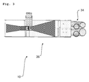
- FIG. 3 shows again an alternative embodiment of the device 10 for heat treatment of packaging goods with adjoining the diffuser region 24 lines 34, leading to the shrink tunnel.
- the entire apparatus 10 is part of a heating chamber 36 of the shrink tunnel.
- FIG. 4 shows an alternative embodiment of the device 10 according to the invention for the heat treatment of packaging goods.
- the device 10 is used for the shrinking treatment of film-wrapped goods such as containers o. The like.
- the device 10 comprises a hot gas generator 12 with a gas burner 14, the combustion products 16 are passed as a hot gas stream in a mixing device 18 which is formed by a channel portion 20 between a running in the direction of constant cross-section inlet area 23 and a flow direction also with a constant Cross-section guided outlet region 25 is arranged.
- a hot gas stream 16 generated by the gas burner 14 is admixed within the mixing device 18 to a cold air stream 26 so that a hot air stream 28 can be removed from the outlet region 25 and used for shrinking the films.
- the mixing device 18 For mixing the hot gas stream 16 with the air flow 26 to be heated, the mixing device 18 has an injection device 30 with a plurality of openings 32 for supplying the combustion products 16 and for mixing them into the air stream 26 of the channel section 20.
- the injection device 30 is again based on the Figures 5 and 6 presented and explained in detail.
- the remaining structure of the device 10 corresponds to the already with reference to the FIGS. 1 to 3 illustrated first embodiment.
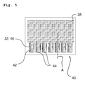
- the schematic representation of Fig. 5 shows a side view of the injection device 30 for the hot gas 16, while the Fig. 6 a perspective view of the Eindüs worn according to Fig. 5 shows.
- the injection device 30 comprises a chamber 38, which is arranged above the channel portion 20 of the mixing device 18, as shown in FIGS FIGS. 1 . 3 and 4 is recognizable. At its bottom, this chamber 38 opens in a tube bundle 40 with a plurality of tubes 42 which are each arranged transversely to the flow direction of the mixing device 18 in the channel section 20.
- the tubes 42 of the tube bundle 40 are each closed at their arranged in the channel section 20 of the mixing device 18 front ends 44 and each have at least one shell-side opening 32 as a hot gas outlet, through which the hot gas 16 can pass into the air flow to be heated 26.
- the shell-side openings 32 of the tubes 42 are each formed as extending parallel to the longitudinal axis of the tubes 42 slots 46.
- each tube 42 may have only one slot 46 or a plurality of such slots 46.
- the slots 46 each have over their longitudinal extent not constant widths.
- the slot width decreases slightly in the direction of the closed end pipe ends 44.
- any or all of the slots 46 may optionally also have constant slot widths, respectively.
- the slots can optionally also be replaced by other suitable geometries, for example by round openings or the like.
- the tubes 42 of the tube bundle 40 each have approximately the same dimensions as well as constant cross sections over their length. As in Fig. 6 recognizable, the tubes 42 may be arranged side by side in several staggered rows. The arrangement of the chamber 38 and the tubes in the air flow of the channel portion 20 can be made variable or depending on the available installation conditions.
- the tubes 42 may optionally be formed in an open variant not shown here, and possibly none of the in the Figures 5 and 6 shown slots 46 have on their lateral surfaces.
- some, several or all of the tubes 42 of the tube bundle 40 may each be at least partially open at their front end tube ends 44 arranged in the channel section of the mixing device.
- the tubes 42 can end open at their front ends 44 optionally with the full pipe cross-section or can have an aperture-like opening, which can each have a smaller opening cross-section than the pipe cross-section.
- numerous combinations with differently shaped and / or placed openings of the tubes 42 are conceivable.
- the two variants mentioned with frontally or shell-side arranged openings can optionally be combined with each other as desired.
Landscapes
- Engineering & Computer Science (AREA)
- Mechanical Engineering (AREA)
- General Engineering & Computer Science (AREA)
- Packages (AREA)
- Containers And Plastic Fillers For Packaging (AREA)
- Wrappers (AREA)
Abstract
Description
- Die Erfindung betrifft eine Vorrichtung zur Wärmebehandlung von Verpackungsgütern, insbesondere von folienumhüllten Gütern, sowie ein entsprechendes Wärmebehandlungsverfahren.
- Zur Verpackung von Gebinden und Verpackungsgütern werden oftmals Folien verwendet, die mittels einer Wärmebehandlung auf die umhüllten Produkte aufgeschrumpft werden. Zur Wärmebehandlung dienen meist sog. Schrumpftunnel, in denen das Aufschrumpfen mittels eines Heißluft- oder Heißgasstroms - auch als Schrumpfgasstrom bezeichnet - erfolgt. Der Schrumpfgasstrom wird meist seitlich auf die jeweiligen, mit der Schrumpffolie bereits umhüllten Verpackungseinheiten aufgebracht, um die Schrumpffolie auf die Verpackungseinheiten bzw. die Gebinde aufzuschrumpfen. Weiterhin ist der Schrumpfgasstrom auch auf die Unterseite des mit der Schrumpffolie umhüllten Produktes gerichtet, um die dortigen, sich überlappenden Enden der Schrumpffolie zu versiegeln, d.h. zu verschweißen oder zu verkleben.
- Derartige Vorrichtungen zum Erzeugen von Heißgas für das Schrumpfen von Kunststofffolien gehen bspw. aus der
DE 31 18 396 A1 sowie aus derDE 38 26 358 A1 hervor. - Der Schrumpfgasstrom wird von einem Heißgas- oder Schrumpfgaserhitzer zur Verfügung gestellt, welcher wenigstens eine Heizeinrichtung aufweist, die bspw. elektrisch oder mit einem gasförmigen oder flüssigen Brennstoff betrieben wird. Eine entsprechende Brennereinheit mit einem gasdurchströmten Porenelement zur Verbrennung von Brenngas und zur Hitzebildung geht aus der
DE 10 2007 030 264 A1 hervor. Das durch das Porenelement geleitete erhitzte Gas wird einer Prozessluft zugeführt, die den Schrumpfgasstrom bildet. - Ein Brenner für ein Gas/Luft-Gemisch ist weiterhin aus der
DE 43 22 109 C2 bekannt. Darüber hinaus sind derartige Heißgaserzeuger in derDE 10 2007 011 526 A1 sowie aus derEP 0 282 849 A1 offenbart. - Ein vorrangiges Ziel der Erfindung besteht darin, ein System zur Erzeugung eines Heißgasstroms aufzuzeigen, mit welchem große Luftmengen auf kurzer Distanz mit geringem Druckverlust gleichmäßig erhitzt werden können. Ein weiteres Ziel der Erfindung besteht darin, ein entsprechendes Verfahren zur Erhitzung von Luft zur Verfügung zu stellen.
- Dieses Ziel wird mittels einer erfindungsgemäßen Vorrichtung zur Wärmebehandlung von Verpackungsgütern erreicht, mit der mittels eines heißen Luft- oder Gasstroms insbesondere eine Schrumpfbehandlung von folienumhüllten Gütern wie Gebinden o. dgl. ermöglicht ist. Die Vorrichtung umfasst einen Heißgaserzeuger mit einem Gasbrenner, dessen Verbrennungsprodukte über mindestens eine Zuführöffnung in eine Mischvorrichtung münden. Diese Mischvorrichtung ist gemäß der vorliegenden Erfindung durch einen Kanalabschnitt gebildet, der zwischen einem Einlaufbereich zur Zufuhr der zu erwärmenden Luft und einem Auslaufbereich zur Abfuhr der mittels der Mischvorrichtung erwärmten Luft angeordnet ist.
- Gemäß einer ersten Ausführungsvariante der vorliegenden Erfindung ist der Kanalabschnitt der Mischvorrichtung zwischen einem trichterartigen, in Strömungsrichtung sich verengendem Leitungsabschnitt und einem sich erweiternden Diffusorbereich angeordnet. Diese erfindungsgemäße Vorrichtung liefert ein System zur Erzeugung eines Heißgasstroms, mit dem große Luftmengen durch direktes Beimengen von Verbrennungsprodukten auf kurzer Distanz mit geringem Druckverlust gleichmäßig erhitzt werden können.
- Zur Vermischung des Heißgasstroms mit der zu erhitzenden Luftströmung weist die Mischvorrichtung mindestens eine Öffnung zur Zuführung der Verbrennungsprodukte und zu deren Zumischung in den Gasstrom des Kanalabschnitts auf.
- Der Kanalabschnitt der Mischvorrichtung kann in Strömungsrichtung einen annähernd konstanten Querschnitt aufweisen. Wahlweise kann der Kanalabschnitt jedoch auch bedarfsgerecht in seinem Querschnitt variiert werden, was zweckmäßigerweise durch Versuche zu ermitteln ist.
- Die Mischvorrichtung ist über wenigstens eine Verbindungsleitung mit einem Heißgasaustritt des Gasbrenners verbunden. Wahlweise können jedoch auch mehrere solcher Verbindungsleitungen vorgesehen sein, so dass bspw. ein längerer Abschnitt der Mischvorrichtung mit mehreren Heißgaszuführungen beaufschlagt sein kann, was einer gleichmäßigen Erwärmung der Luftströmung dienen kann.
- Gemäß einer vorteilhaften Ausführungsvariante der erfindungsgemäßen Vorrichtung mündet die wenigstens eine Verbindungsleitung in einem Rohrbündel mit mehreren Rohren, die jeweils quer zur Strömungsrichtung der Mischvorrichtung in deren Kanalabschnitt angeordnet sind. Ggf. können die Rohre in einem spitzen Winkel von weniger als 90 Grad zur Strömungsrichtung angeordnet sein.
- Gemäß einer ersten Variante der erfindungsgemäßen Vorrichtung können einige, mehrere oder auch alle Rohre des Rohrbündels jeweils an ihren im Kanalabschnitt der Mischvorrichtung angeordneten stirnseitigen Enden zumindest teilweise offen sein. Das bedeutet, dass die Rohre an ihren stirnseitigen Enden wahlweise mit dem vollen Rohrquerschnitt offen enden können oder eine blendenähnliche Öffnung aufweisen können, die jeweils einen geringeren Öffnungsquerschnitt haben kann als der Rohrquerschnitt. Es sei an dieser Stelle darauf hingewiesen, dass diese Ausführungsvariante auch zahlreiche Kombinationen mit unterschiedlich gestalteten und/oder platzierten Öffnungen der Rohre umfassen kann.
- Gemäß einer alternativen Variante der Vorrichtung sind zumindest einige, ggf. auch die Mehrzahl oder alle Rohre des Rohrbündels jeweils an ihren im Kanalabschnitt der Mischvorrichtung angeordneten stirnseitigen Enden verschlossen und weisen jeweils wenigstens eine mantelseitige Öffnung als Heißgasaustritt auf, durch welche das Heißgas in die zu erwärmende Luftströmung übertreten kann. Diese beiden erwähnten Varianten mit stirnseitig oder mantelseitig angeordneten Öffnungen können wahlweise auch beliebig miteinander kombiniert werden.
- Eine vorteilhafte Variante der erfindungsgemäßen Vorrichtung kann vorsehen, dass die wenigstens eine mantelseitige Öffnung der Rohre jeweils als sich parallel zur Längsachse der Rohre erstreckender Schlitz ausgebildet ist. Wahlweise können auch mehrere solcher Schlitze vorhanden sein. Eine alternative Variante kann runde, ovale oder anders geformte Öffnungen zusätzlich zu den Schlitzen oder anstelle der Schlitze vorsehen. Auch können jeweils unterschiedliche Konfigurationen bei mehreren Rohren vorgesehen sein, so dass bspw. mindestens eines der Rohre zwei oder mehr Schlitze aufweist.
- Weiterhin kann es von Vorteil sein, wenn die Schlitze jeweils über ihre Längserstreckung nicht konstante Breiten aufweisen. So kann bspw. die Schlitzbreite in Richtung der verschlossenen stirnseitigen Rohrenden abnehmen.
- Wahlweise können die Rohre des Rohrbündels jeweils annähernd gleiche Abmessungen sowie vorzugsweise konstante Querschnitte über ihre Länge aufweisen. Es sind jedoch auch Varianten mit sich verjüngenden und/oder sich zum verschlossenen Ende hin erweiternden Rohren oder auch nahezu beliebige Kombinationen aus solchen Varianten denkbar.
- Die Erfindung betrifft weiterhin ein Verfahren zur Wärmebehandlung von Verpackungsgütern mittels eines heißen Luft- oder Gasstroms, insbesondere zur Schrumpfbehandlung von folienumhüllten Gütern wie Gebinden o. dgl., bei dem mittels eines Gasbrenners ein Heißgas erzeugt und die heißen Verbrennungsprodukte des Gasbrenners über mindestens eine Zuführöffnung in eine Mischvorrichtung geleitet werden, die durch einen verengten Kanalabschnitt gebildet ist, der zwischen einem trichterartigen, in Strömungsrichtung sich verengendem Leitungsabschnitt und einem sich erweiternden Diffusorbereich angeordnet ist.
- Wahlweise jedoch kann der Einlaufbereich auch einen konstanten und/oder sich nicht trichterartig verengenden Kanalquerschnitt aufweisen. Zudem kann der Auslaufbereich wahlweise ebenfalls einen konstanten und/oder sich nicht trichterartig erweiternden Kanalquerschnitt aufweisen.
- Weitere Merkmale, Ziele und Vorteile der vorliegenden Erfindung gehen aus der folgenden detaillierten Beschreibung einer bevorzugten Ausführungsform der Erfindung hervor, die als nicht einschränkendes Beispiel dient und auf die beigefügten Zeichnungen Bezug nimmt. Gleiche Bauteile weisen dabei grundsätzlich gleiche Bezugszeichen auf und werden teilweise nicht mehrfach erläutert.
-
Fig. 1 zeigt eine schematische Darstellung einer erfindungsgemäßen Vorrichtung zur Wärmebehandlung von Verpackungsgütern. -
Fig. 2 zeigt eine schematische Ansicht eines Strömungskanals der Vorrichtung gemäßFig. 1 . -
Fig. 3 zeigt eine schematische Darstellung einer Ausführungsvariante einer Vorrichtung zur Wärmebehandlung von Verpackungsgütern. -
Fig. 4 zeigt eine schematische Darstellung einer alternativen Ausführungsvariante der erfindungsgemäßen Vorrichtung zur Wärmebehandlung von Verpackungsgütern. -
Fig. 5 zeigt eine schematische Seitenansicht einer Eindüseinrichtung für Heißgas. -
Fig. 6 zeigt eine perspektivische Darstellung der Eindüseinrichtung gemäßFig. 5 . - Die schematische Darstellung der
Fig. 1 zeigt wesentliche Komponenten einer erfindungsgemäßen Vorrichtung 10 zur Wärmebehandlung von hier nicht dargestellten Verpackungsgütern. Diese Vorrichtung 10 dient insbesondere zur Schrumpfbehandlung von folienumhüllten Gütern wie Gebinden o. dgl. mittels eines heißen Luft- oder Gasstroms. Die Vorrichtung 10 umfasst einen Heißgaserzeuger 12 mit einem Gasbrenner 14, dessen Verbrennungsprodukte 16 als Heißgasstrom in eine Mischvorrichtung 18 geleitet werden, welche durch einen Kanalabschnitt 20 gebildet ist, der zwischen einem trichterartigen, in Strömungsrichtung sich verengendem Leitungsabschnitt 22 und einem sich erweiternden Diffusorbereich 24 angeordnet ist. Mittels der gezeigten Vorrichtung 10 wird ein vom Gasbrenner 14 erzeugter Heißgasstrom 16 innerhalb der Mischvorrichtung 18 einem kalten Luftstrom 26 zugemischt, so dass aus dem Diffusorabschnitt 24 ein heißer Luftstrom 28 abgeführt und zum Schrumpfen der Folien genutzt werden kann. - Zur Vermischung des Heißgasstroms 16 mit der zu erhitzenden Luftströmung 26 weist die Mischvorrichtung 18 eine Eindüseinrichtung 30 mit mehreren Öffnungen 32 zur Zuführung der Verbrennungsprodukte 16 und zu deren Zumischung in den Luftstrom 26 des Kanalabschnitts 20 auf. Die Eindüseinrichtung 30 ist anhand der
Figuren 5 und6 im Detail dargestellt und erläutert. - Die schematische Ansicht der
Fig. 2 verdeutlicht den Aufbau eines Strömungskanals 11 der Vorrichtung 10 gemäßFig. 1 mit seinen wesentlichen Komponenten. Der Strömungskanal 11 umfasst den sich trichterförmig verengenden Leitungsabschnitt 22 zur beschleunigten Zuführung von kalter Luft 26, den mittleren Kanalabschnitt 20 mit der darin angeordneten Mischvorrichtung 18 (vgl.Fig. 1 ) sowie den sich daran anschließenden Ausgangsdiffusor 24, der sich im Querschnitt trichterförmig erweitert und der zur Abfuhr der erwärmten Luft 28 zum Schrumpfkanal (nicht dargestellt) dient. - Wie in
Fig. 2 angedeutet, weist der engere mittlere Kanalabschnitt 20 mit der Mischvorrichtung 18 in Strömungsrichtung einen annähernd konstanten Querschnitt auf. - Die schematische Darstellung der
Fig. 3 zeigt nochmals eine Ausführungsvariante der Vorrichtung 10 zur Wärmebehandlung von Verpackungsgütern mit sich an den Diffusorbereich 24 anschließenden Leitungen 34, die zum Schrumpftunnel führen. Die gesamte Vorrichtung 10 ist Teil einer Heizkammer 36 des Schrumpftunnels. - Die schematische Darstellung der
Fig. 4 zeigt eine alternative Ausführungsvariante der erfindungsgemäßen Vorrichtung 10 zur Wärmebehandlung von Verpackungsgütern. Sie sind auch in dieserFig. 4 wiederum die wesentlichen Komponenten der erfindungsgemäßen Vorrichtung 10 zur Wärmebehandlung von hier nicht dargestellten Verpackungsgütern gezeigt. Die Vorrichtung 10 dient zur Schrumpfbehandlung von folienumhüllten Gütern wie Gebinden o. dgl. mittels eines heißen Luft- oder Gasstroms. Die Vorrichtung 10 umfasst einen Heißgaserzeuger 12 mit einem Gasbrenner 14, dessen Verbrennungsprodukte 16 als Heißgasstrom in eine Mischvorrichtung 18 geleitet werden, welche durch einen Kanalabschnitt 20 gebildet ist, der zwischen einem in Strömungsrichtung mit konstantem Querschnitt verlaufenden Einlaufbereich 23 und einem in Strömungsrichtung ebenfalls mit konstantem Querschnitt geführten Auslaufbereich 25 angeordnet ist. Mittels der gezeigten Vorrichtung 10 wird ein vom Gasbrenner 14 erzeugter Heißgasstrom 16 innerhalb der Mischvorrichtung 18 einem kalten Luftstrom 26 zugemischt, so dass aus dem Auslaufbereich 25 ein heißer Luftstrom 28 abgeführt und zum Schrumpfen der Folien genutzt werden kann. - Zur Vermischung des Heißgasstroms 16 mit der zu erhitzenden Luftströmung 26 weist die Mischvorrichtung 18 eine Eindüseinrichtung 30 mit mehreren Öffnungen 32 zur Zuführung der Verbrennungsprodukte 16 und zu deren Zumischung in den Luftstrom 26 des Kanalabschnitts 20 auf. Die Eindüseinrichtung 30 ist wiederum anhand der
Figuren 5 und6 im Detail dargestellt und erläutert. Der übrige Aufbau der Vorrichtung 10 entspricht der bereits anhand derFiguren 1 bis 3 illustrierten ersten Ausführungsvariante. - Die schematische Darstellung der
Fig. 5 zeigt eine Seitenansicht der Eindüseinrichtung 30 für das Heißgas 16, während dieFig. 6 eine perspektivische Darstellung der Eindüseinrichtung gemäßFig. 5 zeigt. Die Eindüseinrichtung 30 umfasst eine Kammer 38, die oberhalb des Kanalabschnitts 20 der Mischvorrichtung 18 angeordnet ist, wie anhand derFiguren 1 ,3 und4 erkennbar ist. An ihrer Unterseite mündet diese Kammer 38 in einem Rohrbündel 40 mit mehreren Rohren 42, die jeweils quer zur Strömungsrichtung der Mischvorrichtung 18 in deren Kanalabschnitt 20 angeordnet sind. Die Rohre 42 des Rohrbündels 40 sind jeweils an ihren im Kanalabschnitt 20 der Mischvorrichtung 18 angeordneten stirnseitigen Enden 44 verschlossen und weisen jeweils wenigstens eine mantelseitige Öffnung 32 als Heißgasaustritt auf, durch welche das Heißgas 16 in die zu erwärmende Luftströmung 26 übertreten kann. - Wie im Ausführungsbeispiel gezeigt sind die mantelseitigen Öffnungen 32 der Rohre 42 jeweils als sich parallel zur Längsachse der Rohre 42 erstreckende Schlitze 46 ausgebildet. Wahlweise kann jedes Rohr 42 nur einen Schlitz 46 oder auch mehrere solcher Schlitze 46 aufweisen.
- Weiterhin ist im Ausführungsbeispiel gemäß
Fig. 5 undFig. 6 vorgesehen, dass die Schlitze 46 jeweils über ihre Längserstreckung nicht konstante Breiten aufweisen. So nimmt die Schlitzbreite in Richtung der verschlossenen stirnseitigen Rohrenden 44 leicht ab. - Für den Fachmann ist es jedoch selbstverständlich, dass alle oder einzelne der Schlitze 46 wahlweise auch jeweils konstante Schlitzbreiten aufweisen können. Darüber hinaus können die Schlitze wahlweise auch durch andere geeignete Geometrien ersetzt sein, bspw. durch runde Durchbrüche o. dgl.
- Die Rohre 42 des Rohrbündels 40 weisen jeweils annähernd gleiche Abmessungen sowie konstante Querschnitte über ihre Länge auf. Wie in
Fig. 6 erkennbar, können die Rohre 42 in mehreren versetzten Reihen nebeneinander angeordnet sein. Die Anordnung der Kammer 38 sowie der Rohre im Luftstrom des Kanalabschnitts 20 kann variabel bzw. je nach den zur Verfügung stehenden Einbauverhältnissen gestaltet werden. - Die Rohre 42 können in einer hier nicht dargestellten Variante wahlweise auch stirnseitig offen ausgebildet sein und ggf. keine der in den
Figuren 5 und6 gezeigten Schlitze 46 an ihren Mantelflächen aufweisen. So können einige, mehrere oder auch alle Rohre 42 des Rohrbündels 40 jeweils an ihren im Kanalabschnitt der Mischvorrichtung angeordneten stirnseitigen Rohrenden 44 zumindest teilweise offen sein. Das bedeutet, dass die Rohre 42 an ihren stirnseitigen Enden 44 wahlweise mit dem vollen Rohrquerschnitt offen enden können oder eine blendenähnliche Öffnung aufweisen können, die jeweils einen geringeren Öffnungsquerschnitt haben kann als der Rohrquerschnitt. Darüber hinaus sind zahlreiche Kombinationen mit unterschiedlich gestalteten und/oder platzierten Öffnungen der Rohre 42 denkbar. Die beiden erwähnten Varianten mit stirnseitig oder mantelseitig angeordneten Öffnungen können wahlweise auch beliebig miteinander kombiniert werden. - Die Erfindung ist nicht auf die vorstehenden Ausführungsbeispiele beschränkt. Vielmehr ist eine Vielzahl von Varianten und Abwandlungen denkbar, die von dem erfindungsgemäßen Gedanken Gebrauch machen und deshalb ebenfalls in den Schutzbereich fallen.
-
- 10
- Vorrichtung zur Wärmebehandlung von Verpackungsgütern
- 11
- Strömungskanal
- 12
- Heißgaserzeuger
- 14
- Gasbrenner
- 16
- Verbrennungsprodukte, Heißgas
- 18
- Mischvorrichtung
- 20
- Kanalabschnitt
- 22
- trichterartiger Leitungsabschnitt
- 23
- Einlaufbereich
- 24
- Diffusorbereich
- 25
- Auslaufbereich
- 26
- kalter Luftstrom
- 28
- heißer Luftstrom
- 30
- Eindüseinrichtung
- 32
- Öffnung
- 34
- Leitungen
- 36
- Heizkammer
- 38
- Kammer
- 40
- Rohrbündel
- 42
- Rohre
- 44
- stirnseitiges Ende
- 46
- Schlitz
Claims (15)
- Vorrichtung (10) zur Wärmebehandlung von Verpackungsgütern mittels eines heißen Luft- oder Gasstroms (28), insbesondere zur Schrumpfbehandlung von folienumhüllten Gütern wie Gebinden o. dgl., mit einem Heißgaserzeuger (12), der einen Gasbrenner (14) umfasst, dessen Verbrennungsprodukte (16) über mindestens eine Zuführöffnung (38) in eine Mischvorrichtung (18) münden, wobei die Mischvorrichtung (18) durch einen Kanalabschnitt (20) gebildet ist, der zwischen einem als Einlaufbereich (23) ausgebildeten Leitungsabschnitt (22) und einem Auslaufbereich (25) angeordnet ist, dadurch gekennzeichnet, dass die Mischvorrichtung (18) mindestens eine Öffnung (32) zur Zuführung der Verbrennungsprodukte (16) und zu deren Zumischung in den Gasstrom (26) des Kanalabschnitts (20) aufweist.
- Vorrichtung nach Anspruch 1, bei der die Mischvorrichtung (18) durch einen Kanalabschnitt (20) gebildet ist, der zwischen einem trichterartigen, in Strömungsrichtung sich verengendem Leitungsabschnitt (22) und einem sich erweiternden Diffusorbereich (24) angeordnet ist.
- Vorrichtung nach Anspruch 1 oder 2, bei der der Kanalabschnitt (20) der Mischvorrichtung (18) in Strömungsrichtung einen annähernd konstanten Querschnitt aufweist.
- Vorrichtung nach einem der Ansprüche 1 bis 3, bei der die Mischvorrichtung (18) über wenigstens eine Verbindungsleitung (38) mit einem Heißgasaustritt des Gasbrenners (14) verbunden ist.
- Vorrichtung nach Anspruch 4, bei der die wenigstens eine Verbindungsleitung (38) in einem Rohrbündel (40) mündet, das quer zur Strömungsrichtung der Mischvorrichtung (18) in deren Kanalabschnitt (20) angeordnet ist.
- Vorrichtung nach Anspruch 5, bei der die Rohre (42) des Rohrbündels (40) jeweils an ihren im Kanalabschnitt (20) der Mischvorrichtung (18) angeordneten stirnseitigen Enden (44) verschlossen sind.
- Vorrichtung nach Anspruch 5, bei der die Rohre (42) des Rohrbündels (40) jeweils an ihren im Kanalabschnitt (20) der Mischvorrichtung (18) angeordneten stirnseitigen Enden (44) zumindest teilweise offen sind.
- Vorrichtung nach einem der Ansprüche 5 bis 7, bei der die Rohre (42) jeweils wenigstens eine mantelseitige Öffnung (32) als Heißgasaustritt aufweisen.
- Vorrichtung nach Anspruch 8, bei der die wenigstens eine mantelseitige Öffnung (32) der Rohre (42) jeweils als sich parallel zur Längsachse der Rohre (42) erstreckender Schlitz (46) ausgebildet ist.
- Vorrichtung nach Anspruch 9, bei der die Schlitze (46) jeweils über ihre Längserstreckung nicht konstante Breiten aufweisen.
- Vorrichtung nach Anspruch 9 oder 10, bei der die Schlitzbreite in Richtung der verschlossenen stirnseitigen Rohrenden (44) abnimmt.
- Vorrichtung nach einem der Ansprüche 9 bis 11, bei der mindestens eines der Rohre (42) zwei oder mehr Öffnungen und/oder Schlitze (46) auf der Mantelfläche aufweist.
- Vorrichtung nach einem der Ansprüche 5 bis 12, bei der die Rohre (42) des Rohrbündels (40) jeweils annähernd gleiche Abmessungen sowie vorzugsweise konstante Querschnitte über ihre Länge aufweisen.
- Verfahren zur Wärmebehandlung von Verpackungsgütern mittels eines heißen Luft- oder Gasstroms (28), insbesondere zur Schrumpfbehandlung von folienumhüllten Gütern wie Gebinden o. dgl., bei dem mittels eines Gasbrenners (14) ein Heißgas (16) erzeugt und die heißen Verbrennungsprodukte (16) des Gasbrenners (14) über mindestens eine Zuführöffnung (38) in eine Mischvorrichtung (18) geleitet werden, die durch einen Kanalabschnitt (20) gebildet ist, der zwischen einem Einlaufbereich (23) und einem Auslaufbereich (25) angeordnet ist.
- Verfahren nach Anspruch 14, bei dem die heißen Verbrennungsprodukte (16) des Gasbrenners (14) über die mindestens eine Zuführöffnung (38) in die Mischvorrichtung (18) geleitet werden, die durch einen verengten Kanalabschnitt (20) gebildet ist, der zwischen einem trichterartigen, in Strömungsrichtung sich verengendem Leitungsabschnitt (22) und einem sich erweiternden Diffusorbereich (24) angeordnet ist.
Applications Claiming Priority (1)
| Application Number | Priority Date | Filing Date | Title |
|---|---|---|---|
| DE102009003575A DE102009003575A1 (de) | 2009-03-06 | 2009-03-06 | Vorrichtung und Verfahren zur Wärmebehandlung von Verpackungsgütern |
Publications (2)
| Publication Number | Publication Date |
|---|---|
| EP2226256A1 true EP2226256A1 (de) | 2010-09-08 |
| EP2226256B1 EP2226256B1 (de) | 2012-05-16 |
Family
ID=41820436
Family Applications (1)
| Application Number | Title | Priority Date | Filing Date |
|---|---|---|---|
| EP10153424A Not-in-force EP2226256B1 (de) | 2009-03-06 | 2010-02-12 | Vorrichtung und Verfahren zur Wärmebehandlung von Verpackungsgütern |
Country Status (4)
| Country | Link |
|---|---|
| US (1) | US8205418B2 (de) |
| EP (1) | EP2226256B1 (de) |
| CN (1) | CN101823579B (de) |
| DE (1) | DE102009003575A1 (de) |
Families Citing this family (8)
| Publication number | Priority date | Publication date | Assignee | Title |
|---|---|---|---|---|
| DE102010007317A1 (de) * | 2010-02-08 | 2011-08-11 | bielomatik Leuze GmbH + Co. KG, 72639 | Verfahren und Vorrichtung zum Aufschmelzen eines thermoplastischen Kunststoffes, insbesondere zum Schweißen von Kunststoffteilen |
| DE102010031800A1 (de) * | 2010-07-20 | 2012-01-26 | Krones Aktiengesellschaft | Anordnung und Verfahren zur Koppelung mehrerer Maschinenbaugruppen einer Behälterbehandlungsmaschine |
| DE102015226466A1 (de) | 2015-12-22 | 2017-06-22 | Krones Aktiengesellschaft | Vorrichtung und Verfahren zum Temperieren einer durch Luft und/oder Gas gebildeten Fluidströmung über Zusammenführen der durch Luft und/oder Gas gebildeten Fluidströmung mit einem Heißgasvolumenstrom |
| JP6861736B2 (ja) * | 2016-05-17 | 2021-04-21 | ビーエイエスエフ・ソシエタス・エウロパエアBasf Se | 成形体を溶着する方法 |
| DE102016213512A1 (de) | 2016-07-22 | 2018-01-25 | Krones Aktiengesellschaft | Schrumpfvorrichtung und Verfahren zum Bereitstellen eines Schrumpfmittels für eine Schrumpfvorrichtung |
| DE102016115673A1 (de) | 2016-08-24 | 2018-03-01 | Krones Aktiengesellschaft | Schrumpfvorrichtung und Verfahren zum Bereitstellen eines Schrumpfmittels für eine Schrumpfvorrichtung |
| US11262130B1 (en) * | 2017-12-14 | 2022-03-01 | Kolorfusion International Inc. | System and method for heat and pressure treatment |
| CN118306637B (zh) * | 2024-06-05 | 2024-09-03 | 合肥清电长信光伏科技有限公司 | 一种热缩机扩膜气体控制设备 |
Citations (1)
| Publication number | Priority date | Publication date | Assignee | Title |
|---|---|---|---|---|
| DE102007030264A1 (de) * | 2007-06-28 | 2009-01-02 | Khs Ag | Brennereinheit |
Family Cites Families (18)
| Publication number | Priority date | Publication date | Assignee | Title |
|---|---|---|---|---|
| DE2645263C2 (de) * | 1976-10-07 | 1984-04-05 | Heinz Leo 4180 Goch Gantevoort | Heizgaserzeuger |
| US4204379A (en) * | 1978-09-05 | 1980-05-27 | W. R. Grace & Co. | Closed circuit shrink tunnel |
| US4373505A (en) * | 1978-09-07 | 1983-02-15 | Modern Home Products Corp. | Adjustable venturi tube assembly for a gas barbecue grill |
| DE3118396A1 (de) | 1981-05-09 | 1982-12-02 | Msk - Verpackungs-Systeme Gmbh, 4192 Kalkar | Vorrichtung zum erzeugen von heissgas fuer das schrumpfen von kunststoffolien |
| DE3335790A1 (de) * | 1983-10-01 | 1985-04-18 | Kallfass Verpackungsmaschinen GmbH, 7440 Nürtingen | Schrumpftunnel |
| US4773384A (en) * | 1983-11-04 | 1988-09-27 | Modern Home Products Corp. | Adjustable gas intake assembly |
| DE8704033U1 (de) | 1987-03-18 | 1987-05-07 | MSK-Verpackungs-Systeme GmbH, 4190 Kleve | Vorrichtung zum Erzeugen von Heißgas für das Schrumpfen von Kunststoffolien |
| DE3826358A1 (de) | 1988-06-02 | 1989-12-07 | Moellers Maschf Gmbh | Vorrichtung zum heissschrumpfen einer folie um einen zu verpackenden gegenstand |
| DE4100657A1 (de) * | 1991-01-11 | 1992-07-16 | Rothenberger Werkzeuge Masch | Tragbarer brenner fuer brenngas mit zwei mischrohren |
| US5877012A (en) | 1993-03-25 | 1999-03-02 | Novartis Finance Corporation | Class of proteins for the control of plant pests |
| DE4322109C2 (de) | 1993-07-02 | 2001-02-22 | Franz Durst | Brenner für ein Gas/Luft-Gemisch |
| US5899048A (en) * | 1993-09-23 | 1999-05-04 | W.R. Grace & Co.-Conn. | Shrink tunnel |
| US5431557A (en) * | 1993-12-16 | 1995-07-11 | Teledyne Industries, Inc. | Low NOX gas combustion systems |
| US5814789A (en) * | 1996-07-18 | 1998-09-29 | Btu International, Inc. | Forced convection furnance gas plenum |
| IT246650Y1 (it) * | 1999-04-15 | 2002-04-09 | Minipack Torre Spa | Macchina confezionatrice a tunnel per l'impaccamento con film termoretraibile |
| US6915620B2 (en) * | 2002-05-10 | 2005-07-12 | Reynolds Metals Company | Shrink tunnel assembly |
| DE102006060109A1 (de) * | 2006-12-20 | 2008-06-26 | Krones Ag | Maschine zum Aufschrumpfen von Schrumpffolie auf Packgut und Verfahren zum Aufschrumpfen |
| DE102007011526A1 (de) | 2007-03-09 | 2008-09-11 | Khs Ag | Schrumpftunnel |
-
2009
- 2009-03-06 DE DE102009003575A patent/DE102009003575A1/de not_active Withdrawn
-
2010
- 2010-02-12 EP EP10153424A patent/EP2226256B1/de not_active Not-in-force
- 2010-03-04 US US12/660,806 patent/US8205418B2/en not_active Expired - Fee Related
- 2010-03-08 CN CN201010129605.2A patent/CN101823579B/zh not_active Expired - Fee Related
Patent Citations (1)
| Publication number | Priority date | Publication date | Assignee | Title |
|---|---|---|---|---|
| DE102007030264A1 (de) * | 2007-06-28 | 2009-01-02 | Khs Ag | Brennereinheit |
Also Published As
| Publication number | Publication date |
|---|---|
| CN101823579A (zh) | 2010-09-08 |
| US8205418B2 (en) | 2012-06-26 |
| US20100223889A1 (en) | 2010-09-09 |
| EP2226256B1 (de) | 2012-05-16 |
| DE102009003575A1 (de) | 2010-09-09 |
| CN101823579B (zh) | 2013-05-29 |
Similar Documents
| Publication | Publication Date | Title |
|---|---|---|
| EP2226256B1 (de) | Vorrichtung und Verfahren zur Wärmebehandlung von Verpackungsgütern | |
| EP2472211B1 (de) | Wärmetauschervorrichtung | |
| DE19812915A1 (de) | Airbagvorrichtung für Kraftfahrzeuge | |
| EP2554483B1 (de) | Schrumpftunnel | |
| DE202013007104U1 (de) | Vorrichtung für automatische Zuführ- und/oder Sortiersysteme zur Führung, Förderung und/oder Positionierung von Behältnisverschlüssen, insbesondere von Behältnisverschlüssen für Tuben, Cremedosen oder Flaschen | |
| DE202006009786U1 (de) | Milchaufschäumvorrichtung | |
| DE3138081C2 (de) | Schussfadeneintragdüse für eine Düsenwebmaschine | |
| DE10252466A1 (de) | Druckluftbetriebene Sandstreuvorrichtung und Verfahren zum Streuen von Sand | |
| EP0160661A1 (de) | Vorrichtung zum pneumatischen und hydraulischen fördern von schüttgut. | |
| EP2586717B1 (de) | Schrumpftunnel | |
| DE10045958A1 (de) | Vorrichtung zum Leiten eines gasförmigen Mediums in eine und/oder aus einer Prozesskammer | |
| DE69205797T2 (de) | Ausrichtungsverfahren und -vorrichtung für einen Ausgabetrichter, insbesondere zum Ausgaben von Zigaretten. | |
| DE102015121598B4 (de) | Düsenvorrichtung für das Heißgasschweißen und Heißgasschweißanlage | |
| DE102013224040A1 (de) | Vorrichtung zum Erzeugen eines oszillierenden Flüssigkeitsstrahls | |
| EP2767476A1 (de) | Schrumpfvorrichtung | |
| EP3172425B1 (de) | Ansaugmodul mit integrierter abgasrückführung für eine brennkraftmaschine | |
| EP4140593B1 (de) | Düsenvorrichtung sowie verfahren zu deren herstellung | |
| DE19525920C2 (de) | Vorrichtung zum mechanischen Reinigen von Gasen und Flüssigkeiten | |
| EP3184443B1 (de) | Vorrichtung und verfahren zum temperieren einer durch luft und/oder gas gebildeten fluidströmung über zusammenführen der durch luft und/oder gas gebildeten fluidströmung mit einem heissgasvolumenstrom | |
| DE4009771C2 (de) | Endstück für eine Einrichtung zum Kühlen von langgestrecktem Walzgut und zum Abstreifen des Kühlmittels | |
| DE20217390U1 (de) | Druckluftbetriebene Sandstreuvorrichtung | |
| EP3585589B1 (de) | Schmelzekanal und extrusionsvorrichtung | |
| EP2862453B1 (de) | Lebensmittelbehandlungsanlgae | |
| DE1660166C3 (de) | Vorrichtung zum Wärmebehandeln von synthetischen Fäden bzw. Garnen | |
| DE29815327U1 (de) | Heizvorrichtung für ein Warmluftsystem |
Legal Events
| Date | Code | Title | Description |
|---|---|---|---|
| PUAI | Public reference made under article 153(3) epc to a published international application that has entered the european phase |
Free format text: ORIGINAL CODE: 0009012 |
|
| AK | Designated contracting states |
Kind code of ref document: A1 Designated state(s): AT BE BG CH CY CZ DE DK EE ES FI FR GB GR HR HU IE IS IT LI LT LU LV MC MK MT NL NO PL PT RO SE SI SK SM TR |
|
| 17P | Request for examination filed |
Effective date: 20101117 |
|
| GRAP | Despatch of communication of intention to grant a patent |
Free format text: ORIGINAL CODE: EPIDOSNIGR1 |
|
| RIC1 | Information provided on ipc code assigned before grant |
Ipc: F27D 7/04 20060101ALI20120111BHEP Ipc: B65B 53/06 20060101AFI20120111BHEP |
|
| RIN1 | Information on inventor provided before grant (corrected) |
Inventor name: NAPRAVNIK, CHRISTIAN |
|
| GRAS | Grant fee paid |
Free format text: ORIGINAL CODE: EPIDOSNIGR3 |
|
| GRAA | (expected) grant |
Free format text: ORIGINAL CODE: 0009210 |
|
| AK | Designated contracting states |
Kind code of ref document: B1 Designated state(s): AT BE BG CH CY CZ DE DK EE ES FI FR GB GR HR HU IE IS IT LI LT LU LV MC MK MT NL NO PL PT RO SE SI SK SM TR |
|
| REG | Reference to a national code |
Ref country code: GB Ref legal event code: FG4D Free format text: NOT ENGLISH |
|
| REG | Reference to a national code |
Ref country code: CH Ref legal event code: EP |
|
| REG | Reference to a national code |
Ref country code: AT Ref legal event code: REF Ref document number: 557978 Country of ref document: AT Kind code of ref document: T Effective date: 20120615 |
|
| REG | Reference to a national code |
Ref country code: IE Ref legal event code: FG4D Free format text: LANGUAGE OF EP DOCUMENT: GERMAN |
|
| REG | Reference to a national code |
Ref country code: DE Ref legal event code: R096 Ref document number: 502010000752 Country of ref document: DE Effective date: 20120712 |
|
| REG | Reference to a national code |
Ref country code: NL Ref legal event code: VDEP Effective date: 20120516 |
|
| REG | Reference to a national code |
Ref country code: LT Ref legal event code: MG4D Effective date: 20120516 |
|
| PG25 | Lapsed in a contracting state [announced via postgrant information from national office to epo] |
Ref country code: FI Free format text: LAPSE BECAUSE OF FAILURE TO SUBMIT A TRANSLATION OF THE DESCRIPTION OR TO PAY THE FEE WITHIN THE PRESCRIBED TIME-LIMIT Effective date: 20120516 Ref country code: PL Free format text: LAPSE BECAUSE OF FAILURE TO SUBMIT A TRANSLATION OF THE DESCRIPTION OR TO PAY THE FEE WITHIN THE PRESCRIBED TIME-LIMIT Effective date: 20120516 Ref country code: NO Free format text: LAPSE BECAUSE OF FAILURE TO SUBMIT A TRANSLATION OF THE DESCRIPTION OR TO PAY THE FEE WITHIN THE PRESCRIBED TIME-LIMIT Effective date: 20120816 Ref country code: LT Free format text: LAPSE BECAUSE OF FAILURE TO SUBMIT A TRANSLATION OF THE DESCRIPTION OR TO PAY THE FEE WITHIN THE PRESCRIBED TIME-LIMIT Effective date: 20120516 Ref country code: CY Free format text: LAPSE BECAUSE OF FAILURE TO SUBMIT A TRANSLATION OF THE DESCRIPTION OR TO PAY THE FEE WITHIN THE PRESCRIBED TIME-LIMIT Effective date: 20120516 Ref country code: SE Free format text: LAPSE BECAUSE OF FAILURE TO SUBMIT A TRANSLATION OF THE DESCRIPTION OR TO PAY THE FEE WITHIN THE PRESCRIBED TIME-LIMIT Effective date: 20120516 Ref country code: IS Free format text: LAPSE BECAUSE OF FAILURE TO SUBMIT A TRANSLATION OF THE DESCRIPTION OR TO PAY THE FEE WITHIN THE PRESCRIBED TIME-LIMIT Effective date: 20120916 |
|
| PG25 | Lapsed in a contracting state [announced via postgrant information from national office to epo] |
Ref country code: SI Free format text: LAPSE BECAUSE OF FAILURE TO SUBMIT A TRANSLATION OF THE DESCRIPTION OR TO PAY THE FEE WITHIN THE PRESCRIBED TIME-LIMIT Effective date: 20120516 Ref country code: HR Free format text: LAPSE BECAUSE OF FAILURE TO SUBMIT A TRANSLATION OF THE DESCRIPTION OR TO PAY THE FEE WITHIN THE PRESCRIBED TIME-LIMIT Effective date: 20120516 Ref country code: PT Free format text: LAPSE BECAUSE OF FAILURE TO SUBMIT A TRANSLATION OF THE DESCRIPTION OR TO PAY THE FEE WITHIN THE PRESCRIBED TIME-LIMIT Effective date: 20120917 Ref country code: GR Free format text: LAPSE BECAUSE OF FAILURE TO SUBMIT A TRANSLATION OF THE DESCRIPTION OR TO PAY THE FEE WITHIN THE PRESCRIBED TIME-LIMIT Effective date: 20120817 Ref country code: LV Free format text: LAPSE BECAUSE OF FAILURE TO SUBMIT A TRANSLATION OF THE DESCRIPTION OR TO PAY THE FEE WITHIN THE PRESCRIBED TIME-LIMIT Effective date: 20120516 |
|
| PG25 | Lapsed in a contracting state [announced via postgrant information from national office to epo] |
Ref country code: EE Free format text: LAPSE BECAUSE OF FAILURE TO SUBMIT A TRANSLATION OF THE DESCRIPTION OR TO PAY THE FEE WITHIN THE PRESCRIBED TIME-LIMIT Effective date: 20120516 Ref country code: SK Free format text: LAPSE BECAUSE OF FAILURE TO SUBMIT A TRANSLATION OF THE DESCRIPTION OR TO PAY THE FEE WITHIN THE PRESCRIBED TIME-LIMIT Effective date: 20120516 Ref country code: RO Free format text: LAPSE BECAUSE OF FAILURE TO SUBMIT A TRANSLATION OF THE DESCRIPTION OR TO PAY THE FEE WITHIN THE PRESCRIBED TIME-LIMIT Effective date: 20120516 Ref country code: NL Free format text: LAPSE BECAUSE OF FAILURE TO SUBMIT A TRANSLATION OF THE DESCRIPTION OR TO PAY THE FEE WITHIN THE PRESCRIBED TIME-LIMIT Effective date: 20120516 Ref country code: CZ Free format text: LAPSE BECAUSE OF FAILURE TO SUBMIT A TRANSLATION OF THE DESCRIPTION OR TO PAY THE FEE WITHIN THE PRESCRIBED TIME-LIMIT Effective date: 20120516 Ref country code: DK Free format text: LAPSE BECAUSE OF FAILURE TO SUBMIT A TRANSLATION OF THE DESCRIPTION OR TO PAY THE FEE WITHIN THE PRESCRIBED TIME-LIMIT Effective date: 20120516 |
|
| PLBE | No opposition filed within time limit |
Free format text: ORIGINAL CODE: 0009261 |
|
| STAA | Information on the status of an ep patent application or granted ep patent |
Free format text: STATUS: NO OPPOSITION FILED WITHIN TIME LIMIT |
|
| 26N | No opposition filed |
Effective date: 20130219 |
|
| PG25 | Lapsed in a contracting state [announced via postgrant information from national office to epo] |
Ref country code: ES Free format text: LAPSE BECAUSE OF FAILURE TO SUBMIT A TRANSLATION OF THE DESCRIPTION OR TO PAY THE FEE WITHIN THE PRESCRIBED TIME-LIMIT Effective date: 20120827 |
|
| REG | Reference to a national code |
Ref country code: DE Ref legal event code: R097 Ref document number: 502010000752 Country of ref document: DE Effective date: 20130219 |
|
| PG25 | Lapsed in a contracting state [announced via postgrant information from national office to epo] |
Ref country code: BG Free format text: LAPSE BECAUSE OF FAILURE TO SUBMIT A TRANSLATION OF THE DESCRIPTION OR TO PAY THE FEE WITHIN THE PRESCRIBED TIME-LIMIT Effective date: 20120816 |
|
| BERE | Be: lapsed |
Owner name: KRONES A.G. Effective date: 20130228 |
|
| PG25 | Lapsed in a contracting state [announced via postgrant information from national office to epo] |
Ref country code: MC Free format text: LAPSE BECAUSE OF NON-PAYMENT OF DUE FEES Effective date: 20130228 |
|
| REG | Reference to a national code |
Ref country code: IE Ref legal event code: MM4A |
|
| PG25 | Lapsed in a contracting state [announced via postgrant information from national office to epo] |
Ref country code: IE Free format text: LAPSE BECAUSE OF NON-PAYMENT OF DUE FEES Effective date: 20130212 Ref country code: BE Free format text: LAPSE BECAUSE OF NON-PAYMENT OF DUE FEES Effective date: 20130228 |
|
| PG25 | Lapsed in a contracting state [announced via postgrant information from national office to epo] |
Ref country code: MT Free format text: LAPSE BECAUSE OF FAILURE TO SUBMIT A TRANSLATION OF THE DESCRIPTION OR TO PAY THE FEE WITHIN THE PRESCRIBED TIME-LIMIT Effective date: 20120516 |
|
| REG | Reference to a national code |
Ref country code: CH Ref legal event code: PL |
|
| GBPC | Gb: european patent ceased through non-payment of renewal fee |
Effective date: 20140212 |
|
| PG25 | Lapsed in a contracting state [announced via postgrant information from national office to epo] |
Ref country code: LI Free format text: LAPSE BECAUSE OF NON-PAYMENT OF DUE FEES Effective date: 20140228 Ref country code: CH Free format text: LAPSE BECAUSE OF NON-PAYMENT OF DUE FEES Effective date: 20140228 |
|
| PG25 | Lapsed in a contracting state [announced via postgrant information from national office to epo] |
Ref country code: GB Free format text: LAPSE BECAUSE OF NON-PAYMENT OF DUE FEES Effective date: 20140212 |
|
| PG25 | Lapsed in a contracting state [announced via postgrant information from national office to epo] |
Ref country code: SM Free format text: LAPSE BECAUSE OF FAILURE TO SUBMIT A TRANSLATION OF THE DESCRIPTION OR TO PAY THE FEE WITHIN THE PRESCRIBED TIME-LIMIT Effective date: 20120516 |
|
| PG25 | Lapsed in a contracting state [announced via postgrant information from national office to epo] |
Ref country code: TR Free format text: LAPSE BECAUSE OF FAILURE TO SUBMIT A TRANSLATION OF THE DESCRIPTION OR TO PAY THE FEE WITHIN THE PRESCRIBED TIME-LIMIT Effective date: 20120516 |
|
| PG25 | Lapsed in a contracting state [announced via postgrant information from national office to epo] |
Ref country code: HU Free format text: LAPSE BECAUSE OF FAILURE TO SUBMIT A TRANSLATION OF THE DESCRIPTION OR TO PAY THE FEE WITHIN THE PRESCRIBED TIME-LIMIT; INVALID AB INITIO Effective date: 20100212 Ref country code: MK Free format text: LAPSE BECAUSE OF FAILURE TO SUBMIT A TRANSLATION OF THE DESCRIPTION OR TO PAY THE FEE WITHIN THE PRESCRIBED TIME-LIMIT Effective date: 20120516 Ref country code: LU Free format text: LAPSE BECAUSE OF NON-PAYMENT OF DUE FEES Effective date: 20130212 |
|
| REG | Reference to a national code |
Ref country code: FR Ref legal event code: PLFP Year of fee payment: 7 |
|
| REG | Reference to a national code |
Ref country code: AT Ref legal event code: MM01 Ref document number: 557978 Country of ref document: AT Kind code of ref document: T Effective date: 20150212 |
|
| PG25 | Lapsed in a contracting state [announced via postgrant information from national office to epo] |
Ref country code: AT Free format text: LAPSE BECAUSE OF NON-PAYMENT OF DUE FEES Effective date: 20150212 |
|
| REG | Reference to a national code |
Ref country code: FR Ref legal event code: PLFP Year of fee payment: 8 |
|
| REG | Reference to a national code |
Ref country code: FR Ref legal event code: PLFP Year of fee payment: 9 |
|
| PGFP | Annual fee paid to national office [announced via postgrant information from national office to epo] |
Ref country code: DE Payment date: 20190129 Year of fee payment: 10 Ref country code: IT Payment date: 20190221 Year of fee payment: 10 Ref country code: FR Payment date: 20190111 Year of fee payment: 10 |
|
| REG | Reference to a national code |
Ref country code: DE Ref legal event code: R119 Ref document number: 502010000752 Country of ref document: DE |
|
| PG25 | Lapsed in a contracting state [announced via postgrant information from national office to epo] |
Ref country code: FR Free format text: LAPSE BECAUSE OF NON-PAYMENT OF DUE FEES Effective date: 20200229 Ref country code: DE Free format text: LAPSE BECAUSE OF NON-PAYMENT OF DUE FEES Effective date: 20200901 |
|
| PG25 | Lapsed in a contracting state [announced via postgrant information from national office to epo] |
Ref country code: IT Free format text: LAPSE BECAUSE OF NON-PAYMENT OF DUE FEES Effective date: 20200212 |