EP2224435A1 - Disque optique, appareil de reproduction de disque optique, dispositif et procédé de production de disque optique - Google Patents
Disque optique, appareil de reproduction de disque optique, dispositif et procédé de production de disque optique Download PDFInfo
- Publication number
- EP2224435A1 EP2224435A1 EP09824518A EP09824518A EP2224435A1 EP 2224435 A1 EP2224435 A1 EP 2224435A1 EP 09824518 A EP09824518 A EP 09824518A EP 09824518 A EP09824518 A EP 09824518A EP 2224435 A1 EP2224435 A1 EP 2224435A1
- Authority
- EP
- European Patent Office
- Prior art keywords
- sub information
- information
- optical disc
- recorded
- sub
- Prior art date
- Legal status (The legal status is an assumption and is not a legal conclusion. Google has not performed a legal analysis and makes no representation as to the accuracy of the status listed.)
- Withdrawn
Links
Images


Classifications
-
- G—PHYSICS
- G11—INFORMATION STORAGE
- G11B—INFORMATION STORAGE BASED ON RELATIVE MOVEMENT BETWEEN RECORD CARRIER AND TRANSDUCER
- G11B20/00—Signal processing not specific to the method of recording or reproducing; Circuits therefor
- G11B20/00086—Circuits for prevention of unauthorised reproduction or copying, e.g. piracy
- G11B20/00094—Circuits for prevention of unauthorised reproduction or copying, e.g. piracy involving measures which result in a restriction to authorised record carriers
- G11B20/00115—Circuits for prevention of unauthorised reproduction or copying, e.g. piracy involving measures which result in a restriction to authorised record carriers wherein the record carrier stores a unique medium identifier
-
- G—PHYSICS
- G11—INFORMATION STORAGE
- G11B—INFORMATION STORAGE BASED ON RELATIVE MOVEMENT BETWEEN RECORD CARRIER AND TRANSDUCER
- G11B20/00—Signal processing not specific to the method of recording or reproducing; Circuits therefor
- G11B20/00086—Circuits for prevention of unauthorised reproduction or copying, e.g. piracy
- G11B20/0021—Circuits for prevention of unauthorised reproduction or copying, e.g. piracy involving encryption or decryption of contents recorded on or reproduced from a record carrier
- G11B20/00217—Circuits for prevention of unauthorised reproduction or copying, e.g. piracy involving encryption or decryption of contents recorded on or reproduced from a record carrier the cryptographic key used for encryption and/or decryption of contents recorded on or reproduced from the record carrier being read from a specific source
- G11B20/00253—Circuits for prevention of unauthorised reproduction or copying, e.g. piracy involving encryption or decryption of contents recorded on or reproduced from a record carrier the cryptographic key used for encryption and/or decryption of contents recorded on or reproduced from the record carrier being read from a specific source wherein the key is stored on the record carrier
- G11B20/00376—Circuits for prevention of unauthorised reproduction or copying, e.g. piracy involving encryption or decryption of contents recorded on or reproduced from a record carrier the cryptographic key used for encryption and/or decryption of contents recorded on or reproduced from the record carrier being read from a specific source wherein the key is stored on the record carrier the key being stored by varying the pit format, e.g. depth, width, length or edge positions
-
- G—PHYSICS
- G11—INFORMATION STORAGE
- G11B—INFORMATION STORAGE BASED ON RELATIVE MOVEMENT BETWEEN RECORD CARRIER AND TRANSDUCER
- G11B20/00—Signal processing not specific to the method of recording or reproducing; Circuits therefor
- G11B20/00086—Circuits for prevention of unauthorised reproduction or copying, e.g. piracy
- G11B20/00572—Circuits for prevention of unauthorised reproduction or copying, e.g. piracy involving measures which change the format of the recording medium
- G11B20/00586—Circuits for prevention of unauthorised reproduction or copying, e.g. piracy involving measures which change the format of the recording medium said format change concerning the physical format of the recording medium
- G11B20/00594—Circuits for prevention of unauthorised reproduction or copying, e.g. piracy involving measures which change the format of the recording medium said format change concerning the physical format of the recording medium wherein the shape of recording marks is altered, e.g. the depth, width, or length of pits
-
- G—PHYSICS
- G11—INFORMATION STORAGE
- G11B—INFORMATION STORAGE BASED ON RELATIVE MOVEMENT BETWEEN RECORD CARRIER AND TRANSDUCER
- G11B20/00—Signal processing not specific to the method of recording or reproducing; Circuits therefor
- G11B20/00086—Circuits for prevention of unauthorised reproduction or copying, e.g. piracy
- G11B20/00572—Circuits for prevention of unauthorised reproduction or copying, e.g. piracy involving measures which change the format of the recording medium
- G11B20/00586—Circuits for prevention of unauthorised reproduction or copying, e.g. piracy involving measures which change the format of the recording medium said format change concerning the physical format of the recording medium
- G11B20/00608—Circuits for prevention of unauthorised reproduction or copying, e.g. piracy involving measures which change the format of the recording medium said format change concerning the physical format of the recording medium wherein the material that the record carrier is made of is altered, e.g. adding reactive dyes that alter the optical properties of a disc after prolonged exposure to light or air
-
- G—PHYSICS
- G11—INFORMATION STORAGE
- G11B—INFORMATION STORAGE BASED ON RELATIVE MOVEMENT BETWEEN RECORD CARRIER AND TRANSDUCER
- G11B20/00—Signal processing not specific to the method of recording or reproducing; Circuits therefor
- G11B20/00086—Circuits for prevention of unauthorised reproduction or copying, e.g. piracy
- G11B20/00572—Circuits for prevention of unauthorised reproduction or copying, e.g. piracy involving measures which change the format of the recording medium
- G11B20/00615—Circuits for prevention of unauthorised reproduction or copying, e.g. piracy involving measures which change the format of the recording medium said format change concerning the logical format of the recording medium, e.g. the structure of sectors, blocks, or frames
- G11B20/0063—Circuits for prevention of unauthorised reproduction or copying, e.g. piracy involving measures which change the format of the recording medium said format change concerning the logical format of the recording medium, e.g. the structure of sectors, blocks, or frames wherein the modification to the logical format mainly concerns management data, e.g., by changing the format of the TOC or the subcode
-
- G—PHYSICS
- G11—INFORMATION STORAGE
- G11B—INFORMATION STORAGE BASED ON RELATIVE MOVEMENT BETWEEN RECORD CARRIER AND TRANSDUCER
- G11B20/00—Signal processing not specific to the method of recording or reproducing; Circuits therefor
- G11B20/00086—Circuits for prevention of unauthorised reproduction or copying, e.g. piracy
- G11B20/00681—Circuits for prevention of unauthorised reproduction or copying, e.g. piracy involving measures which prevent a specific kind of data access
- G11B20/00688—Circuits for prevention of unauthorised reproduction or copying, e.g. piracy involving measures which prevent a specific kind of data access said measures preventing that a usable copy of recorded data can be made on another medium
-
- G—PHYSICS
- G11—INFORMATION STORAGE
- G11B—INFORMATION STORAGE BASED ON RELATIVE MOVEMENT BETWEEN RECORD CARRIER AND TRANSDUCER
- G11B20/00—Signal processing not specific to the method of recording or reproducing; Circuits therefor
- G11B20/00086—Circuits for prevention of unauthorised reproduction or copying, e.g. piracy
- G11B20/00681—Circuits for prevention of unauthorised reproduction or copying, e.g. piracy involving measures which prevent a specific kind of data access
- G11B20/00695—Circuits for prevention of unauthorised reproduction or copying, e.g. piracy involving measures which prevent a specific kind of data access said measures preventing that data are read from the recording medium
-
- G—PHYSICS
- G11—INFORMATION STORAGE
- G11B—INFORMATION STORAGE BASED ON RELATIVE MOVEMENT BETWEEN RECORD CARRIER AND TRANSDUCER
- G11B7/00—Recording or reproducing by optical means, e.g. recording using a thermal beam of optical radiation by modifying optical properties or the physical structure, reproducing using an optical beam at lower power by sensing optical properties; Record carriers therefor
- G11B7/004—Recording, reproducing or erasing methods; Read, write or erase circuits therefor
- G11B7/005—Reproducing
- G11B7/0053—Reproducing non-user data, e.g. wobbled address, prepits, BCA
-
- G—PHYSICS
- G11—INFORMATION STORAGE
- G11B—INFORMATION STORAGE BASED ON RELATIVE MOVEMENT BETWEEN RECORD CARRIER AND TRANSDUCER
- G11B7/00—Recording or reproducing by optical means, e.g. recording using a thermal beam of optical radiation by modifying optical properties or the physical structure, reproducing using an optical beam at lower power by sensing optical properties; Record carriers therefor
- G11B7/007—Arrangement of the information on the record carrier, e.g. form of tracks, actual track shape, e.g. wobbled, or cross-section, e.g. v-shaped; Sequential information structures, e.g. sectoring or header formats within a track
- G11B7/00736—Auxiliary data, e.g. lead-in, lead-out, Power Calibration Area [PCA], Burst Cutting Area [BCA], control information
-
- G—PHYSICS
- G11—INFORMATION STORAGE
- G11B—INFORMATION STORAGE BASED ON RELATIVE MOVEMENT BETWEEN RECORD CARRIER AND TRANSDUCER
- G11B7/00—Recording or reproducing by optical means, e.g. recording using a thermal beam of optical radiation by modifying optical properties or the physical structure, reproducing using an optical beam at lower power by sensing optical properties; Record carriers therefor
- G11B7/007—Arrangement of the information on the record carrier, e.g. form of tracks, actual track shape, e.g. wobbled, or cross-section, e.g. v-shaped; Sequential information structures, e.g. sectoring or header formats within a track
- G11B7/00745—Sectoring or header formats within a track
-
- G—PHYSICS
- G11—INFORMATION STORAGE
- G11B—INFORMATION STORAGE BASED ON RELATIVE MOVEMENT BETWEEN RECORD CARRIER AND TRANSDUCER
- G11B20/00—Signal processing not specific to the method of recording or reproducing; Circuits therefor
- G11B20/10—Digital recording or reproducing
- G11B20/12—Formatting, e.g. arrangement of data block or words on the record carriers
- G11B20/1217—Formatting, e.g. arrangement of data block or words on the record carriers on discs
- G11B2020/1218—Formatting, e.g. arrangement of data block or words on the record carriers on discs wherein the formatting concerns a specific area of the disc
- G11B2020/1222—ECC block, i.e. a block of error correction encoded symbols which includes all parity data needed for decoding
-
- G—PHYSICS
- G11—INFORMATION STORAGE
- G11B—INFORMATION STORAGE BASED ON RELATIVE MOVEMENT BETWEEN RECORD CARRIER AND TRANSDUCER
- G11B20/00—Signal processing not specific to the method of recording or reproducing; Circuits therefor
- G11B20/10—Digital recording or reproducing
- G11B20/12—Formatting, e.g. arrangement of data block or words on the record carriers
- G11B2020/1264—Formatting, e.g. arrangement of data block or words on the record carriers wherein the formatting concerns a specific kind of data
- G11B2020/1265—Control data, system data or management information, i.e. data used to access or process user data
- G11B2020/1287—Synchronisation pattern, e.g. VCO fields
-
- G—PHYSICS
- G11—INFORMATION STORAGE
- G11B—INFORMATION STORAGE BASED ON RELATIVE MOVEMENT BETWEEN RECORD CARRIER AND TRANSDUCER
- G11B2220/00—Record carriers by type
- G11B2220/20—Disc-shaped record carriers
- G11B2220/25—Disc-shaped record carriers characterised in that the disc is based on a specific recording technology
- G11B2220/2537—Optical discs
- G11B2220/2562—DVDs [digital versatile discs]; Digital video discs; MMCDs; HDCDs
Definitions
- a third aspect of the present invention provides the optical disc of the first aspect of the present invention in which the second sub information is information generated by data-conversion of predetermined information using the first sub information.
- the predetermined information may be information set in advance, such as encryption key information and disc ID information.
- a fourth aspect of the present invention provides the optical disc of the third aspect of the present invention in which the first sub information includes information indicating an initial value that is used to generate a pseudo random number sequence.
- the second sub information is information generated by scrambling the predetermined information using the pseudo random number sequence that is generated using the initial value.
- a fifth aspect of the present invention provides the optical disc of the first aspect of the present invention in which the second sub information is recorded based on a recording position indicated by the first sub information.
- a sixth aspect of the present invention provides the optical disc of the fifth aspect of the present invention in which the first sub information includes information indicating a recording start position of the second sub information.
- the second sub information is recorded from the recording start position indicated by the first sub information that is paired with the second sub information.
- a seventh aspect of the present invention provides the optical disc of the first aspect of the present invention in which the first sub information is information generated by scrambling predetermined information using an initial value that is used to generate a predetermined pseudo random number sequence. The second sub information is information generated based on the initial value.
- An eighth aspect of the present invention provides the optical disc of the first aspect of the present invention in which the first sub information is recorded as being coded to enable a reading error of the first sub information to be detected.
- a ninth aspect of the present invention provides the optical disc of the first aspect of the present invention in which the first sub information includes information unique to a master for the optical disc.
- a tenth aspect of the present invention provides the optical disc of the first aspect of the present invention in which the second sub information is recorded after the optical disc is molded.
- An eleventh aspect of the present invention provides the optical disc of the first aspect of the present invention in which the second sub information includes information unique to the optical disc.
- the main information reading unit irradiates the concave or convex recording marks with laser light, and reads the main information based on a reflected light element corresponding to the concave or convex recording marks included in reflected light of the laser light.
- the first sub information detection unit detects the first sub information recorded so as to correspond to each unit of the main information that has been divided in predetermined units.
- the second sub information reading unit reads second sub information based on a change in a reflection intensity that differs from a reflection intensity of the reflected light element corresponding to the concave or convex recording marks included in the reflected light.
- the testing unit detects a correlation between the detected first sub information and the read second sub information, and outputs the predetermined information that is used to decrypt the main information based on a result of the detection.
- An eighteenth aspect of the present invention provides an optical disc playback apparatus arranged to play an optical disc, the optical disc being recorded withmain information that is to be decrypted using predetermined information by arranging concave or convex recording marks on a spiral track and having first sub information recorded by shifting the concave or convex recording marks, deforming the concave or convex recording marks, or altering a pattern of the concave or convex recording marks.
- the apparatus includes a main information reading unit, a second sub information reading unit, a testing unit, and a first sub information detection unit.
- a twenty first aspect of the present invention provides an optical disc manufacturing apparatus arranged to record second sub information onto an optical disc, the optical disc being recorded with main information that is to be decrypted using predetermined information by arranging concave or convex recording marks on a spiral track and having first sub information.
- the apparatus includes a first sub information detection unit and a second sub information recording unit.
- the first sub information detection unit detects the first sub information by detecting a shift of the concave or convex recording marks, a deformation of the concave or convex recording marks, or an alteration of a pattern of the concave or convex recording marks for each unit of the main information that has been recorded as being divided in predetermined units.
- a twenty fifth aspect of the present invention provides the optical disc manufacturing apparatus of the twenty first aspect of the present invention in which the first sub information detection unit detects the first sub information recorded for a first predetermined unit of the main information simultaneously with the second sub information recording unit recording the second sub information for the first predetermined unit of the main information.
- the first sub information recorded for the first predetermined unit of the main information is used to record other second sub information for a second predetermined unit of the main information that is continuous to and follows the first predetermined unit of the main information in a direction of the spiral track.
- the first sub information is detected by detecting a shift of the concave or convex recording marks, a deformation of the concave or convex recording marks, or an alteration of a pattern of the concave or convex recording marks for a predetermined unit of the main information that has been recorded as being divided in predetermined units.
- the second sub information recording process the second sub information is recorded in accordance with the control signal generated in association with the detected first sub information.
- the optical disc, the optical disc manufacturing apparatus, the optical disc playback apparatus, and the optical disc manufacturing method of the present invention improve resistance to unauthorized copying of content stored in an optical disc by recording a plurality of sets of sub information on the optical disc, and also reduce the overhead for reading the sub information by recording the plurality of sets of sub information into the same area from which the plurality of sets of sub information can be read simultaneously. Also, the optical disc, the optical disc manufacturing apparatus, the optical disc playback apparatus, and the optical disc manufacturing method of the present invention eliminate unauthorized playback apparatuses that would bypass readout of the sub information by recording the plurality of sets of sub information in a manner that the plurality of sets of sub information are associated with one another. The present invention therefore enables digital content to be distributed in a reliable manner using an optical disc.
- first sub information is recorded as being superimposed on information representing the content, or content information, by changing the recording signals for the authored content 22 based on the first sub information.
- the first sub information is recorded by altering the synchronization codes.
- the authored content 22 is modulated in accordance with the first sub information by a formatter (not shown)
- the patterns of synchronization codes which are inserted in fixed cycles, are altered in accordance with the first sub information.
- the first sub information is recorded onto the optical disc master 32 together with the content information.
- the present embodiment describes the case in which the mastering maker 30 generates the first sub information.
- the first sub information may be, for example, a random number sequence that differs depending on each optical disc master.
- the testing 60 signals are read for testing from an optical disc 61 on which the second sub information has been recorded through the second sub information recording 50.
- the testing 60 first includes first sub information readout 62, in which the first sub information is read from the optical disc by detecting the altered synchronization codes in the same manner as in the second sub information recording 50. While the first sub information is being read, second sub information readout 63 is performed, in which the second sub information is read from the optical disc by detecting the locally changed reflectivity of the recording marks of the optical disc.
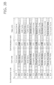
- Figs. 3A and 3B show the sector structure of a DVD.
- Fig. 3A shows a typical sector structure of a DVD.
- the sector consists of the first to the twenty sixth frames, or 26 frames in total,.
- Each frame consists of a synchronization code having 32 channel bits and a data code having 1456 channel bits.
- the synchronization codes are given reference numerals SY0 to SY7, each of which indicates a synchronization code pattern that can be identified by an ID code included in the corresponding synchronization code.
- the DVD has eight synchronization code patterns SY0 to SY7.
- Fig. 3B shows the sector structure of the optical disc on which the first sub information has been recorded.
- the sub information is recorded using either altered or unaltered synchronization codes in the fourth, eighth, twelfth, sixteenth, twentieth, and twenty fourth frames.
- the altered synchronization code indicates that the bit value of 1 is recorded as the first sub information
- the unaltered synchronization code indicates that the bit value of 0 is recorded as the sub information.
- the synchronization codes of the fourth, sixteenth, and twentieth frames have been altered from the normal patterns SY5, SY6, and SY7 to the abnormal pattern SY8.
- Each altered code is extracted as the bit value of 1, whereas each unaltered code is extracted as the bit value of 0.
- the resulting 6-bit information will be 100110, which is read as the first sub information.
- the 48-bit first sub information which has been recorded in each of the first and second areas, is coded using error correction codes.
- the 48-bit first sub information consists of 32-bit data representing the first sub information and the 16-bit correction parity. Reed-Solomon codes are used as the error correction codes.
- the first sub information recorded in the first area consists of 32-bit information indicating the scrambling initial value, which is used to scramble the second sub information, and its 16-bit correction parity.
- the first sub information recorded in the second area consists of 32-bit information indicating the recording start position of the second sub information and its 16-bit correction parity.
- the first sub information is coded using error correction codes, and thus includes the 16-bit parity.
- the erroneously read bit can be corrected to enable the first sub information to be extracted in a correct manner.
- the first sub information is coded using the 16-bit Reed-Solomon codes. This enables the first sub information to be corrected in 1-byte units. Such error correction of the first sub information increases the possibility of the first sub information being read in a stable manner even when the accuracy of the read first sub information may be degraded by flaws, finger marks, or dirt on the disc. When the information contains errors that cannot be corrected, the state in which the information contains uncorrectable errors will be detected.
- the recording marks may be convex marks.
- the height of each convex mark may also be set to about ⁇ or 4.
- the reflective film 1L is irradiated with laser light having controlled focus, the phase of reflected light of the laser light irradiating the concave or convex recording marks and the phase of reflected light of the laser light reaching mirror plane portions other than the concave or convex recording marks will differ from each other by 180 degrees (will be inverted).
- the concave or convex recording marks are irradiated with laser light having a laser spot larger than the width of the marks.
- an optical disc manufacturing apparatus (described later) first reads the ECC block #0 of the optical disc. Then, the optical disc manufacturing apparatus obtains, as the first sub information, the scrambling initial value of the second sub information and the recording start position of the second sub information. While reading the first sub information from the ECC block #0 (701), the apparatus can also read the main information including the content information.
- the scrambling initial value and the recording start position of the second sub information that have been recorded in the ECC block #0 as the first sub information are used as the scrambling initial value and the recording start position of the second sub information that are to be recorded into the next ECC block, namely the ECC block #1 (702).
- the first sub information that has been recorded in the ECC block #1 (702) is read while the second sub information is being recorded into the ECC block #1 (702).
- the first sub information that has been recorded in the ECC block #1 (702) indicates the scrambling initial value and the recording start position of the second sub information that is to be recorded into the ECC block #2 (703), which is continuous to the ECC block #1 (702).
- the first sub information has been recorded in the ECC block #1 (702) by altering the ID codes of the synchronization codes that are inserted in units of frames of the ECC block #1 (702) as shown in Fig. 3A .
- the encryption key information (scrambling-target information) etc. are scrambled (707) using a random number sequence generated by the random number generator (706) to record the second sub information into the ECC block #2 (703).
- the scrambling initial value and the recording start position of the second sub information that have been recorded in the ECC block #1 as the first sub information are used as the scrambling initial value and the recording start position of the second sub information that are to be recorded into the next ECC block, namely the ECC block #2 (703).
- the optical disc has ECC blocks, which function as the units for recording information, and the first sub information has been recorded onto the optical disc in units of ECC blocks by altering the ID codes of the synchronization codes included in the frames.
- the first sub information indicates the scrambling initial value and the recording start position of the second sub information, which are used to record the second sub information into the next ECC block continuous to the currently processed ECC block in the track direction.
- the first sub information is read simultaneously as when the second sub information is recorded using the first sub information that has been read in an ECC block immediately preceding the currently processed ECC block in the track direction.
- the recording start position of the second sub information, which is recorded as the first sub information is specifically a sector address at which the recording of the second sub information is to be started in an ECC block immediately following the ECC block from which the first sub information is read.
- the recording start position of the second sub information can therefore be changed in units of ECC blocks. This prevents a malicious third party from analyzing the second sub information in an unauthorized manner.
- the present embodiment describes the case in which the recording start position of the second sub information, which is recorded as the first sub information, is specifically the sector address at which the recording of the second sub information is to be started in an ECC block immediately following the ECC block from which the first sub information is read, the present invention should not be limited to this structure.
- the recording start position of the second sub information may be a position deviating in channel bits from the beginning position of the ECC block from which the recording is to be started or a position of a frame from which the recording of the second sub information is to be started.
- the present embodiment is designed to include any means for changing the recording start position of the second sub information in units of ECC blocks, which is included in the scope of the present invention.
- both the first sub information and the second sub information are recorded in synchronization with the units of ECC blocks, or sectors or frames. This enables the first sub information and the second sub information to be read simultaneously with the main information, without requiring to use synchronization codes unique to the first sub information and the second sub information.
- the first sub information and the second sub information are recorded with different methods.
- the first sub information is recorded by altering the synchronization codes of the frames
- the second sub information is recorded by changing the reflectivity of the reflective film through laser light irradiation and forming the reflectivity changing marks.
- both the first sub information and the second sub information, which have been recorded onto the optical disc with different methods not only need to be copied into the same area but also need to be copied simultaneously. This would be almost impossible for a third party who is not notified of the methods that have been used to record the first sub information and the second sub information.
- This structure enables copyright protection of content stored in an optical disc to be achieved with a level higher than conventional copyright protection.
- the sub information may not be associated with the synchronization codes. It is only required that the first sub information and the second sub information be recorded in synchronization with the main information.
- the first sub information and the second sub information may be recorded in units of clusters, such as frames, sectors, or ECC blocks, or may be recorded in a manner that a plurality of such clusters are used as a single unit for recording the information.
- clusters such as frames, sectors, or ECC blocks
- the second sub information has been recorded on the optical disc by lowering the reflectivity of the reflective film at positions corresponding to the concave or convex recording marks through laser light irradiation and forming the reflectivity changing marks.
- a playback apparatus (described later) first reads the ECC block #0 (801). Then, the playback apparatus obtains, as the first sub information, the scrambling initial value of the second sub information and the recording start position of the second sub information, which can be used to extract the second sub information recorded in the ECC block #1 (802). While reading the first sub information from the ECC block #0 (801), the apparatus can also read the main information including the content information.
- the ECC block #1 (802) which is continuous to the ECC block #0 (801) in the track direction, is read next.
- the scrambling initial value of the second sub information that has been read as the first sub information from the ECC block #0 (801) is set to be used by a random number generator (804).
- the ECC block #1 (802) is read until the current reading position reaches the recording start position of the second sub information that has been read as the first sub information from the ECC block #0 (801).
- the second sub information is read from the ECC block #1 (802) and descrambled (805) using a random number sequence generated by the random number generator (804) to detect the encryption key information (scrambling-target information) etc. from the ECC block #1 (802).
- the first sub information that has been recorded in the ECC block #0 indicates the scrambling initial value and the recording start position of the second sub information to be read from the next ECC block, namely the ECC block #1 (802).
- the ECC block #2 (803), which is continuous to the ECC block #1 (802) in the track direction, is read next.
- the scrambling initial value of the second sub information that has been read as the first sub information from the ECC block #1 (802) is set to be used by a random number generator (806).
- the ECC block #2 (803) is read until the current reading position reaches the recording start position of the second sub information that has been read as the first sub information from the ECC block #1 (802).
- the second sub information is read from the ECC block #2 (803) and descrambled (807) using a random number sequence generated by the random number generator 806 to detect the key information (scrambling-target information) etc. from the ECC block #2 (803).
- the first sub information that has been recorded in the ECC block #1 indicates the scrambling initial value and the recording start position of the second sub information that is to be read from the next ECC block, namely the ECC block #2 (803).
- the first sub information that has been recorded in the ECC block #2 (803) is read while the second sub information is being read from the ECC block #2 (803).
- the first sub information that has been recorded in the ECC block #2 (803) indicates the scrambling initial value and the recording start position of the second sub information that is read from an ECC block (not shown) continuous to the ECC block #2 (803).
- the first sub information has been recorded in the ECC block #2 (803) by altering the ID codes of the synchronization codes that are inserted in units of frames of the ECC block #2 (803).
- the optical disc has ECC blocks, which are the units for recording information, and the first sub information has been recorded onto the optical disc in units of ECC blocks by altering the ID codes of the synchronization codes for the frames.
- the first sub information indicates the scrambling initial value and the recording start position of the second sub information, which are used to record the second sub information into the next ECC block continuous to the currently processed ECC block in the track direction.
- the second sub information and the first sub information are read simultaneously.
- the second sub information is recorded by locally lowering the reflectivity of the reflective film of the optical disc through irradiation of laser light having a changed intensity.
- the second sub information is read by detecting changes in the reflectivity that are different from the frequency elements corresponding to changes in the reflectivity of the concave or convex recording marks.
- the read second sub information is descrambled based on the random number sequence initialized using the scrambling initial value, which has been read as the first sub information from the immediately preceding ECC block. More specifically, the second sub information is read by detecting changes in the intensity of the reflected light in the readout waveform of the reflectivity changing marks formed on the reflective film and by starting the readout from the recording start position of the second sub information that has been read as the first sub information from the immediately preceding ECC block in the track direction.
- the present embodiment is designed to include any means for changing the recording start position of the second sub information in units of ECC blocks, which is included in the scope of the present invention.
- both the first sub information and the second sub information are recorded in synchronization with the units of ECC blocks, or sectors or frames. This enables the first sub information and the second sub information to be read simultaneously with the main information, without requiring to use synchronization codes unique to the first sub information and the second sub information.
- the first sub information and the second sub information are recorded with different methods.
- the disc which fails to contain the second sub information including the encryption key information for the content, would have no value.
- the first sub information indicating the scrambling initial value used for reading the second sub information and the recording start position of the second sub information cannot be read from the created disc copy. In that case, the second sub information cannot be read from the disc. As a result, the content cannot be read from the disc.
- both the first sub information and the second sub information, which have been recorded onto the optical disc with different methods not only need to be copied into the same area but also need to be copied simultaneously. This would be almost impossible for a third party who is not notified of the methods that have been used to record the first sub information and the second sub information.
- This structure enables copyright protection of content stored in an optical disc to be achieved with a level higher than conventional copyright protection.
- a playback apparatus (described later) first reads the ECC block #0 (901). Then, as the first sub information, the scrambling initial value of the second sub information and the recording start position of the second sub information. While reading the first sub information from the ECC block #0 (901), the apparatus can also read the main information including the content information.
- the ECC block #1 (902) which is continuous to the ECC block #0 (901) in the track direction, is read next as in the example shown in Fig. 8 .
- the scrambling initial value of the second sub information that has been read as the first sub information from the ECC block #0 (901) is set to be used by a random number generator (905).
- the ECC block #1 (902) is read until the current reading position reaches the recording start position of the second sub information that has been read as the first sub information from the ECC block #0 (901).
- the second sub information read from the ECC block #1 (902) is descrambled (902) using a random number sequence generated by the random number generator (905) to detect the encryption key information (scrambling-target information) etc.
- the first sub information recorded in the ECC block #0 indicates the scrambling initial value and the recording start position of the second sub information that is to be read from the next ECC block, namely the ECC block #1 (902).
- the first sub information that has been recorded in the ECC block #1 (902) is read while the second sub information is being read from the ECC block #1.
- the first sub information that has been recorded in the ECC block #1 (902) indicates the scrambling initial value and the recording start position of the second sub information that is to be read from the ECC block #2 (903), which is continuous to the ECC block #1 (902).
- the first sub information has been recorded in the ECC block #1 (902) by altering the ID codes of the synchronization codes that are inserted in units of frames of the ECC block #1 (902) as shown in Fig. 3A .
- Fig. 3A In the example shown in Fig.
- a reading error is assumed to have occurred in reading the first sub information from the ECC block #1 (902), or more specifically in reading at least one of the scrambling initial value of the second sub information and the recording start position of the second sub information from the ECC block #1 (902).
- the first sub information has been coded using Reed-Solomon codes as shown in Fig. 5 .
- the first sub information is subjected to error correction after the first sub information is completely read from the ECC block #1 (902). When errors that cannot be corrected are detected in the error correction, the state in which the information contains uncorrectable errors will be detected.
- the ECC block #2 (903), which is continuous to the ECC block #1 (902) in the track direction, is read next.
- the first sub information that has been recorded in the ECC block #1 (902), which is to be used to read the second sub information recorded in the ECC block #2 (903) has not been read successfully due to a reading error or the like.
- the operation of reading the second sub information from the ECC block #2 (903) is suspended. The reading operation is suspended because the scrambling initial value and the reading start position of the second sub information that will be necessary to detect the encryption key etc. from the second sub information are unknown.
- the encryption key etc. are detected by detecting changes in the reflectivity through integration.
- the scrambling initial value and or or the recording start position are unknown, continuing the operation of detecting the encryption key etc. through integration may cause unintended integration, which can degrade the accuracy of the read encryption key information etc.
- the playback apparatus determines that the first sub information has not been read successfully from the immediately preceding ECC block after error correction
- the apparatus suspends the operation for reading the second sub information, and holds the result of integration performed to read the second sub information from the immediately preceding ECC block.
- This enables the encryption key information etc. to be read in a stable manner.
- the operation for reading the first sub information from the ECC block #2 is performed.
- the ECC block #3 (904) which is continuous to the ECC block #2 (903) in the track direction, is read next.
- the second sub information is read from the ECC block #3 (904) using the scrambling initial value and the recording start position that have been recorded as the first sub information in the ECC block #2 (903).
- the operation for reading the second sub information from the immediately preceding ECC block, namely the ECC block #2 (903) has been suspended.
- the operation for reading the second sub information is resumed by performing integration using the integral that is used to read the second sub information from the ECC block #1 (902).
- the second sub information is read based on whether the first sub information has been read successfully from the immediately preceding ECC block. Even when an error occurs in reading the first sub information from the immediately preceding ECC block, this method prevents such an error from affecting the second sub information read from other ECC blocks.
- the first sub information in the present embodiment has the parity bit for error correction using Reed-Solomon codes, which enables determination as to whether the first sub information has been read successfully as shown in Fig. 5
- the present invention should not be limited to this structure. It is only required that the determination as to whether the read first sub information is correct be performed. Thus, error detection codes may be used instead of the error correction codes.
- Fig. 10 shows the structure of an apparatus for recording the second sub information on an optical disc 1100 according to the first embodiment of the present invention, or namely an optical disc manufacturing apparatus 1000.
- the optical disc manufacturing apparatus 1000 includes a spindle motor 1001, an optical head 1002, an analogue signal processing unit 1003, a digital signal processing unit 1004, a formatter 1005, a timing signal generation unit 1006, a first sub information detection unit 1007, a first sub information error correction unit 1008, a pseudo random number generation unit 1009, a scrambling-target information storage FIFO 1010, a scrambling unit 1011, a PE modulation unit 1012, a laser intensity control unit 1013, and a laser driver 1014.
- the optical disc 1100 on which the second sub information is to be recorded is formed by transfer from the optical disc master on which the first sub information has been prerecorded, and then forming a protective layer and labeling etc.
- the first sub information has been recorded by altering the ID codes of the synchronization codes that are inserted in units of frames as shown in Fig. 3A .
- the first sub information indicates the scrambling initial value used to record the second sub information and the recording start position of the second sub information.
- the unique sub information is recorded in units of ECC blocks.
- the unique first sub information recorded in units of ECC blocks has been generated by, for example, subjecting sector addresses to data conversion, and has been recorded onto the optical disc master.
- the method for recording the sub information by altering the synchronization codes is described in detail in, for example, Japanese Unexamined Patent Publication No. 2002-93060 , and will not be described in detail herein.
- the optical disc 1001 is mounted on the manufacturing apparatus, and then the spindle motor 1001 rotates the optical disc 1001 through designated rotation control (at a constant linear velocity (CLV) in this example).
- the optical head 1002 irradiates the optical disc 1001, which is being rotated by the spindle motor 1001, with laser light, and obtains the readout waveform based on reflected light of the laser light, and outputs the obtained readout waveform to the analogue signal processing unit 1003.
- the analogue signal processing unit 1003 amplifies or equalizes the readout waveform output from the optical head 1002 to generate an analogue readout signal, and outputs the analogue readout signal to the digital signal processing unit 1004.
- the digital signal processing unit 1004 converts the analogue readout signal output from the analogue signal processing unit 1003 through analogue to digital conversion.
- the digital signal processing unit 1004 then operates its internal phase locked loop (PLL) circuit to generate a clock signal in synchronization with the readout signal.
- PLL phase locked loop
- the digital signal processing unit 1004 digitizes the readout signal in synchronization with the clock signal to generate a digital readout signal, and outputs the generated digital readout signal to the formatter 1005.
- the formatter 1005 detects the timings corresponding to synchronization codes that are inserted in fixed cycles from the digital readout signal output from the digital signal processing unit 1004.
- the formatter 1005 Based on the detected timings, the formatter 1005 divides the digital readout signal in units of frames, and demodulates the frame addresses using ID information of the synchronization codes to detect frame positions. The formatter 1005 then groups the frames into sectors, each of which consists of 26 frames according to the detected frame positions, and extracts sector addresses attached to the sectors. The formatter 1005 further groups the sectors into ECC blocks each consisting of 16 sectors according to the sector addresses, and performs error correction in units of ECC blocks to extract the main information in units of 32 KB.
- the formatter 1005 also generates a synchronization signal, which is a timing signal indicating the timing at which a synchronization code inserted in units of frames is detected, the beginning position of a sector, the address of a sector, and the beginning position of an ECC block, and outputs the generated signal to the timing signal generation unit 1006 and the first sub information detection unit 1007.
- the formatter 1005 also generates a synchronization code ID signal indicating the type of an ID code of a synchronization code that is inserted in units of frames, and outputs the synchronization code ID signal to the first sub information detection unit 1007.
- the timing signal generation unit 1006 generates a block signal indicating the position of an ECC block from which the first sub information is to be read based on the timing signal provided from the formatter 1005, and outputs the generated signal to the first sub information detection unit 1007.
- the position of the ECC block from which the first sub information is to be read is indicated using a sector address, and is designated by a system controller (not shown) in the present embodiment.
- the readout position of the first sub information set by the system controller may be a predetermined address, or may be a value indicating the recording position obtained by playing back the optical disc in advance and stored in a control area of the optical disc.
- the control area may be included in a burst cutting area (BCA), in which information is recorded as marks in the form of a bar code by removing the corresponding portions of the reflective film with laser light irradiation.
- BCA burst cutting area
- the timing signal generation unit 1006 outputs a sequence updating signal at every predetermined timing to the pseudo random number generation unit 1009, which is used for recording the second sub information.
- the timing signal generation unit 1006 also outputs a second sub information updating signal indicating the timing at which bits of the second sub information to be recorded at every predetermined timing are transmitted.
- the sequence updating signal is output at every 104 th channel bit in the 1456 channel bits of each frame excluding the synchronization code part (32 channel bits) at the beginning of the frame. This means that the sequence updating signal is output 14 times per frame.
- the second sub information updating signal is output at every third frame in the 24 frames of each sector excluding the first frame (frame at the beginning of the sector) and the sixteenth frame (frame at the end of the sector) of the sector.
- the second sub information updating signal is output eight times per sector. More specifically, with the recording format used in the present embodiment, 1-bit second sub information is recorded at every third frame, and consequently 8-bit second sub information is recorded in each sector and 128-bit second sub-information is recorded in each ECC block.
- the first sub information detection unit 1007 detects the first sub information using the synchronization signal and the synchronization code ID signal, which are provided from the formatter 1005, based on the block signal indicating a block from which the first sub information is to be detected, which is provided from the timing signal generation unit 1006.
- the first sub information is recorded in the manner described with reference to Fig. 4 , and 48-bit information consisting of the 32-bit sub information and the 16-bit Reed-Solomon parity bit is recorded in each of the first area, which consists of the first to eight sectors, and the second area, which consists of the ninth to sixteenth sectors, within the ECC block.
- the scrambling initial value used to record the second sub information is recorded in the first area, whereas the recording start position of the second sub information is recorded in the second area.
- the scrambling initial value and the recording start position of the second sub information serve as the first sub information.
- the first sub information is recorded using either altered or unaltered ID codes of the synchronization codes in the fourth, eighth, twelfth, sixteenth, twentieth, and twenty fourth frames in the first to twenty sixth frames within the sector, to the abnormal pattern SY8, which is not included in a normal disc as described with reference to Figs. 3A and 3B .
- the bit value of 1 is extracted as the first sub information bit.
- the bit value of 0 is extracted as the first sub information bit.
- the resulting 6-bit first sub information is recorded into the single frame.
- the first sub information detection unit 1007 detects the frame addresses from the synchronization codes at the timing indicated by the block signal, which has been generated to indicate the detection timing of the first sub information based on the timing signal.
- the first sub information detection unit 1007 detects the first sub information by determining whether the ID codes of the synchronization codes of the fourth, eighth, twelfth, sixteenth, twentieth, and twenty fourth frames have been altered to the pattern SY8.
- the first sub information detection unit 1007 outputs the detected first sub information to the first sub information error correction unit 1008.
- the first sub information error correction unit 1008 subjects the first sub information detected by the first sub information detection unit 1007 to error correction. As shown in Fig.
- the scrambling initial value of the second sub information and the recording start position information of the second sub information, which serve as the first sub information, are coded using Reed-Solomon codes.
- the first sub information error correction unit 1008 subjects the first sub information to error correction and generates corrected first sub information, and outputs the corrected first sub information to the pseudo random number generator 1009.
- the first sub information error correction unit 1008 receives the detected entire 96-bit first sub information in units of ECC blocks from the first sub information detection unit 1007.
- the first sub information detection unit 1007 clears the first sub information that has been stored internally when outputting the detected first sub information to the first sub information error correction unit 1008, and newly performs the operation for detecting the first sub information from the subsequent ECC blocks in the track direction.
- the pseudo random number generation unit 1009 generates a pseudo random number sequence using, as an initial value, the corrected first sub information generated by the first sub information error correction unit 1008.
- the pseudo random number generation unit 1009 outputs, to the scrambling unit 1011, a single bit of the pseudo random number sequence generated at every timing when the sequence updating signal is output from the timing signal generation unit 1006.
- the pseudo random number generation unit 1009 is formed by a typical M-sequence generator including a feedback shift register.
- the initial value indicated by the first sub information is set in the shift register at the beginning position of the ECC block into which the second sub information is recorded.
- the random number sequence is updated by shifting the shift register by a single bit at every timing when the sequence updating signal is output from the timing signal generation unit 1006.
- the sequence updating signal is output from the timing signal generation unit 1006 at every 104 th channel bit for the 1456 channel bit length of the frame excluding the 32 channel bits of the synchronization code part 32 of the frame.
- a single bit of the pseudo random number sequence is generated and output to the scrambling unit 1011 for every 104 th channel bit.
- the pseudo random number generation unit 1009 starts generating the pseudo random number sequence at the beginning of the sector indicated by the recording start position of the second sub information, which is recorded as the first sub information.
- the scrambling-target information storage FIFO 1010 is a first-in, first-out (FIFO) stack.
- the scrambling-target information storage FIFO 1010 stores the scrambling-target information provided in advance from a system controller (not shown), which is information obtained by concatenating the encryption key information and the disc identification information.
- a single bit of the scrambling-target information stored in the FIFO is output to the scrambling unit 1011 at every timing when the second sub information updating signal is output from the timing signal generation unit 1006.
- the second sub information updating signal is output from the timing signal generation unit 1006 at every third frame excluding the first frame (frame at the beginning of the sector) and the twenty sixth frame (frame at the end of the sector) of the sector corresponding to the recording start position of the second recording signal, which is detected as the first sub information by the first sub information detection unit 1007.
- the scrambling-target information storage FIFO 1010 1-bit information is selected for every third frame in accordance with the second sub information updating signal, and the selected 1-bit information is output to the scrambling unit 1011.
- the PE modulation unit 1012 sets the bit length of the first half 52 channel bits of the 104 channel bits to a high (H) level and the latter half 52 channel bits to a low (L) level to generate a PE-modulated second sub information signal.
- the PE modulation unit 1012 sets the bit length of the first half 52 channel bits of the 104 channel bits to L and the latter half 52 channel bits to H to generate a PE-modulated second sub information signal.
- the generated PE-modulated second sub information signal is output to the laser intensity control unit 1013.
- the laser intensity control unit 1013 generates a laser intensity control signal for controlling the laser intensity, and outputs the generated signal to the laser driver 1014.
- the laser intensity control unit 1013 sets the intensity of laser light used to irradiate the optical disc 1100 higher than the readout level when the PE-modulated second sub information signal output from the PE modulation unit 1012 is at a H level.
- the laser intensity control unit 1013 maintains the intensity of the laser light at the readout level when the PE-modulated second sub information signal is at a L level.
- the laser driver 1014 drives a laser oscillator that irradiates the optical disc with laser light.
- the laser driver 1014 irradiates the optical disc 1100 with laser light having an intensity controlled in accordance with a laser intensity control signal.
- the optical disc manufacturing apparatus 1000 of the present embodiment reads the first sub information based on whether the synchronization codes inserted in units of frames have been altered in the preset recording areas of the first sub information.
- the optical disc manufacturing apparatus 1000 sets the scrambling initial value, which has been recorded as the first sub information, to be used by the pseudo random number generation unit at the beginning position of an ECC block that is continuous to the currently processed ECC block, from which the first sub information has been read, in the direction of the track, and also records the second sub information one bit at a time from the recording start position of the second sub information, which has been recorded as the first sub information.
- the second sub information is recorded after the information is scrambled using the pseudo random number sequence generated using the scrambling initial value, which has been recorded as the first sub information read from the immediately preceding ECC block, and the scrambled information is then modulated by phase encoding. Also, while the second sub information is being recorded, the apparatus performs the operation for detecting the first sub information that is used to record the second sub information into an ECC block immediately following the currently processed ECC block in which the second sub information is being recorded.
- the second sub information is not recorded in the synchronization code part of the frame. This is due to the following reason. To record the second sub information in the synchronization code part of the frame, the synchronization code part needs to be irradiated with laser light having an intensity higher than the normal readout level. However, if the synchronization code part is irradiated with laser light having an intensity other than the normal readout level, the altered ID information of the synchronization codes may fail to be read in a stable manner. This may disable the first sub information to be detected successfully. To avoid this, the second sub information is not recorded in the synchronization code part of the frame.
- the second sub information is not recorded in the first frame (frame at the beginning of the sector) and the twenty sixth frame (frame at the end of the sector) of the sector. This is because a sector address is recorded in the first frame of each sector in a DVD-ROM.
- laser light irradiation having an intensity higher than the normal readout level to form the reflectivity changing marks having changed reflectivity is not performed in the first frame, in which the sector address is recorded, and in the twenty sixth frame, which is a frame immediately preceding the first frame of the next sector. This enables the playback apparatus for the optical disc to read the sector addresses in a stable manner.
- Figs. 11(a) to 11(c) are timing charts showing the specific timing at which the initial value that has been detected as the first sub information is set to be used by the pseudo random number generation unit 1009 for recording the second sub information in the optical disc manufacturing apparatus 1000 of the present embodiment described with reference to Fig. 10 when the optical disc manufacturing apparatus 1000 records the second sub information.
- Fig. 11(a) shows ECC blocks that are continuous to each another in the track direction of the optical disc on which the second sub information is to be recorded. More specifically, Fig. 11(a) shows an ECC block #n and its immediately following ECC block #n + 1.
- the scrambling initial value and the recording start position of the second sub information that is to be recorded into the ECC block #n + 1 are detected from the ECC block #n as the first sub information. Based on the detected first sub information, the second sub information is recorded into the ECC block #n + 1.
- Fig. 11(b) shows a boundary between the ECC blocks #n and #n + 1 shown in Fig. 11(a) . At the boundary between the two blocks, a sector #16, which is the last sector of the ECC block #n, and a sector #1, which is the first sector of the ECC block #n + 1, are arranged adjacent to each other as well as continuous to each other.
- Fig. 11(c) shows a boundary between the sectors #16 and #1 shown in Fig. 11(b) .
- a frame #26, which is the last frame of the ECC block #n and a frame #1, which is the first frame of the ECC block #n + 1 are arranged adjacent to each other as well as continuous to each other.
- the scrambling initial value read as the first sub information from the ECC block #n is set to be used by the pseudo random number generation unit 1009 at the beginning position of the ECC block #n + 1.
- the set scrambling initial value is then used to generate a pseudo random number sequence.
- the second sub information is not recorded in the first frame of the sector.
- the scrambling initial value may be set at any timing within the frame #1 of the sector #1 included in the ECC block #n + 1.
- the recording may be started from a sector corresponding to the recording start position of the second sub information for the ECC block #n + 1, which is recorded in the ECC block #n as the first sub information.
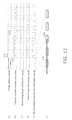
- Figs. 12(a) to 12(f) are timing charts showing the unique operation of the optical disc manufacturing apparatus shown in Fig. 10 .
- Fig. 12(a) shows a digital readout signal output from the digital signal processing unit 1004 to the formatter 1005, and specifically shows a frame readout signal having a synchronization code 1201, which is inserted in units of frames, and a data code part 1202.
- Fig. 12(b) shows a pseudo random number sequence that is generated by the pseudo random number generation unit 1009. The pseudo random number sequence is output one bit at a time in accordance with a sequence updating signal provided from the timing signal generation unit 1006.
- the sequence updating signal is output for every 104 th channel bit of the data code part of the frame, which is the part of the frame excluding the synchronization code part.
- a single bit of the pseudo random number sequence is output for every 104 th channel bit of the data code part of the frame excluding the synchronization code part.
- Fig. 12(c) shows a scrambling-target information signal that is output from the scrambling-target information storage FIFO 1010 to the scrambling unit 1011.
- the scrambling-target information signal is output one bit at a time in accordance with a second sub information updating signal provided from the timing signal generation unit 1006.
- the second sub information updating signal is output for every third frame in the frames of the sector excluding the first frame and the twenty sixth frame.
- the scrambling-target information signal is updated for every third frame and is output one bit at a time.
- Fig. 12(d) shows a second sub information signal that is output from the scrambling unit 1011 to the PE modulation unit 1012.
- the scrambling unit 1011 of the present embodiment generates the second sub information signal by scrambling the scrambling-target information signal using an exclusive OR of the input pseudo random number sequence ( Fig. 12(b) ) and the scrambling-target information signal ( Fig.12(b) ).
- Fig. 12(e) shows a PE-modulated second sub information signal, which is output from the PE modulation unit 1012 to the laser intensity control unit 1013.
- the PE modulation unit 1012 modulates the input second sub information ( Fig. 12(d) ) by phase encoding.
- the PE modulation unit 1012 sets the first half 52-channel bits to H and the latter half 52-channel bits to L to generate a PE-modulated second sub information signal.
- the PE modulation unit 1012 sets the first half 52-bit channel bit section to L and the latter half 52-channel bit section to H to generate a PE-modulated second sub information signal.
- the optical disc is irradiated with laser light having the normal readout level so that the reflectivity of the reflective film remains unchanged. Through this laser light irradiation, the second sub information is recorded.
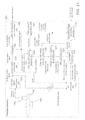
- Fig. 13 shows the structure of an optical disc playback apparatus 1300 for playing the optical disc 1100 of the first embodiment on which the first sub information and the second sub information have been recorded.
- the optical disc playback apparatus 1300 includes a spindle motor 1301, an optical head 1302, an analogue signal processing unit 1303, a digital signal processing unit 1304, a formatter 1305, a main information error correction unit 1306, a timing signal generation unit 1307, a first sub information detection unit 1308, a first sub information error correction unit 1309, a pseudo random number generation unit 1310, a PE modulation unit 1311, an LPF 1312, an AD conversion unit 1313, a correlation detection unit 1314, and a scrambling-target information detection unit 1315.
- the optical head 1302, the analogue signal processing unit 1303, the digital signal processing unit 1304, the formatter 1305, and the main information error correction unit 1306 form a main information readout unit that irradiates the concave or convex recording marks of the optical disc and reads the main information based on reflected light elements from the concave or convex recording marks included in the reflected light of the laser light irradiation.
- the LPF 1312 and the AD conversion unit 1313 form a second sub information readout unit that reads the second sub information.
- the pseudo random number generation unit 1310, the PE modulation unit 1311, the correlation detection unit 1314, and the scrambling-target information detection unit 1315 form a testing unit that detects the correlation, or in other words the association between the first sub information and the second sub information, and outputs the encryption key information etc. that are used to read the main information based on the detection result.
- the optical disc 1100 of the present embodiment on which the first sub information and the second sub information have been recorded is mounted on the playback apparatus, and then the spindle motor 1310 rotates the optical disc 1100 through CLV rotation control.
- the optical head 1302 irradiates the optical disc 1100, which is being rotated by the spindle motor 1301, with laser light, and extracts the readout waveform based on reflected light of the laser light, and outputs the extracted readout waveform to the analogue signal processing unit 1303.
- the analogue signal processing unit 1303 amplifies or equalizes the readout waveform output from the optical head 1302 to generate an analogue readout signal, and outputs the analogue readout signal to the digital signal processing unit 1304 and the LPF 1312.
- the digital signal processing unit 1304 converts the analogue readout signal input from the analogue signal processing unit 1303 through analogue to digital conversion.
- the digital signal processing unit 1304 then operates its internal PLL circuit to generate a clock signal in synchronization with the readout signal.
- the digital signal processing unit 1304 digitizes the readout signal in synchronization with the clock signal to generate a digital readout signal, and outputs the generated digital readout signal to the formatter 1305.
- the formatter 1305 detects the synchronization codes that are inserted in fixed cycles from the digital readout signal output from the digital signal processing unit 1304. Based on the detected timings, the formatter 1305 divides the digital readout signal in units of frames, and extracts the frame addresses using the ID codes of the synchronization codes. The formatter 1305 then groups the frames into sectors each of which has a sector address and consists of 26 frames. The digital readout signal is futher devided in units of ECC blocks, which are coded using error correction codes, according to the sector addresses provided to the sectors. The formatter 1305 then outputs, as main information readout data, the digital readout signal that has been divided in units of ECC blocks to the main information error correction unit 1306.
- the formatter 1305 also generates a synchronization signal, which is a timing signal indicating the timing at which a synchronization code inserted in units of frames is detected, the address of a sector, and the beginning position of an ECC block, and outputs the generated signal to the timing signal generation unit 1307 and the first sub information detection unit 1308.
- the formatter 1305 also generates a synchronization code ID signal after detecting an ID code of a synchronization code that is inserted in units of frames, and outputs the synchronization code ID signal to the first sub information detection unit 1308.
- the main information error correction unit 1306 subjects the main information to error correction performed in units of ECC blocks based on the main information readout data provided from the formatter 1305, and extracts 32-KB user data as the main information, and outputs the extracted main information to, for example, an image processing block or a personal computer (not shown).
- the timing signal generation unit 1307 generates a block signal indicating a timing for an ECC block from which the first sub information is to be read based on the synchronization signal provided from the formatter 1305, and outputs the generated signal to the first sub information detection unit 1308.
- the position of the ECC block from which the first sub information is to be read is designated by a system controller (not shown).
- the recording position of the first sub information may be a predetermined common address, a sector address read from a control area of the optical disc, or a sector address read from a BCA of the optical disc.
- the timing signal generation unit 1307 outputs a sequence updating signal indicating the timing at which a pseudo random number sequence generated by the pseudo random number generation unit 1310 is to be updated in accordance with the input synchronization signal, and outputs the sequence updating signal to the pseudo random number generation unit 1310.
- the sequence updating signal is output for every 104 th channel bit of the 1456-channel bit data code part of the frame, which is the part of the frame excluding the synchronization code part (the first 32-channel bits). In this case, the sequence updating signal is output 14 times per frame.
- the timing signal generation unit 1307 also outputs a second sub information updating timing signal to the scrambling-target information detection unit 1315 in accordance with the input synchronization signal.
- a second sub information updating timing signal is output for every third frame in the 24 frames of the sector excluding the first frame (frame at the beginning of the sector) and the twenty sixth frame (frame at the end of the sector) of the sector.
- the second sub information updating timing signal is output for every third frame.
- the first sub information detection unit 1308 detects the first sub information using the synchronization signal and the synchronization code ID signal, which are provided from the formatter 1305, based on the block signal indicating a block from which the first sub information is to be detected, which is provided from the timing signal generation unit 1307.
- the first sub information is recorded in the manner described with reference to Fig. 4 , and 48-bit information consisting of the 32-bit sub information and the 16-bit Reed-Solomon parity bit is recorded in each of the first area, which consists of the first to eighth sectors of the ECC block, and the second area, which consists of the ninth to sixteenth sectors, within the ECC block.
- the scrambling initial value used to record the second sub information and the recording start position of the second sub information are recorded in the first area.
- the scrambling initial value and the recording start position of the second sub information serve as the first sub information.
- the first sub information is recorded using either altered or unaltered ID codes of the synchronization codes in the fourth, eighth, twelfth, sixteenth, twentieth, and twenty fourth frames in the first to twenty sixth frames within the sector, to the abnormal pattern SY8, which is not included in a normal disc as described above with reference to Figs. 3A and 3B .
- the altered code having the pattern SY8 the bit value of 1 is extracted as the first sub information bit.
- the bit value of 0 is extracted as the first sub information bit.
- the resulting 6-bit first sub information is recorded into the frame.
- the first sub information detection unit 1007 detects the frame addresses from the synchronization codes at the timing indicated by the block signal, which indicates the detection timing of the first sub information and has been generated based on the timing signal.
- the first sub information detection unit 1007 detects the first sub information by determining whether the ID codes of the synchronization codes of the fourth, eighth, twelfth, sixteenth, twentieth, and twenty fourth frames have been altered to the pattern SY8.
- the first sub information detection unit 1007 outputs the detected first sub information to the first sub information error correction unit 1309.
- the first sub information error correction unit 1309 subjects the first sub information detected by the first sub information detection unit 1308 to error correction. As shown in Fig.
- the scrambling initial value of the second sub information and the recording start position information of the second sub information, which serve as the first sub information, are coded using Reed-Solomon codes.
- the first sub information error correction unit 1309 subjects the first sub information to error correction and generates corrected first sub information, and outputs the corrected first sub information to the pseudo random number generator 1310.
- the first sub information error correction unit 1309 detects the state in which the information contains uncorrectable errors or the state in which the error correction has been unsuccessful, and outputs an unsuccessful correction notification signal indicating that state to the correlation detection unit 1314.
- the first sub information error correction unit 1309 receives the detected entire 96-bit first sub information in units of ECC blocks from the first sub information detection unit 1308.
- the first sub information detection unit 1308 clears the first sub information that has been stored internally when outputting the detected first sub information to the first sub information error correction unit 1309, and newly performs the operation for detecting the first sub information from the subsequent ECC blocks in the track direction.
- the pseudo random number generation unit 1310 generates a pseudo random number sequence using, as an initial value, the corrected first sub information generated by the first sub information error correction unit 1309.
- the pseudo random number generation unit 1310 outputs, to the PE modulation unit 1311, a single bit of the pseudo random number sequence generated at every timing when the sequence updating signal is output from the timing signal generation unit 1307.
- the pseudo random number generation unit 1310 has the same structure as the pseudo random number generation unit 1009 included in the optical disc manufacturing apparatus 1000 described with reference to Fig. 10 .
- the pseudo random number generation unit 1310 and the pseudo random number generation unit 1009 generate the same pseudo random number when using the same initial value.
- the PE modulation unit 1311 modulates the pseudo random number sequence input from the pseudo random number generation unit 1310 by phase encoding (PE).
- PE phase encoding
- the PE modulation unit 1311 sets the bit length of the first half 52 channel bits of the 104 channel bits to 1 and the latter half 52 channel bits to 0 to generate a PE-modulated pseudo random number sequence signal.
- the PE modulation unit 1311 sets the bit length of the first half 52 channel bits to 0 and sets the latter half 52 channel bits to 1 to generate a PE-modulated pseudo random number sequence signal.
- the generated PE-modulated pseudo random number sequence signal is output to the correlation detection unit 1314.
- the LPF 1312 is a typical low pass filter that passes low-frequency elements.
- the LPF 1312 generates an LPF envelope signal by extracting only low-frequency elements of the analogue readout signal that is output from the analogue signal processing unit 1303, and outputs the generated signal to the AD conversion unit 1313.
- the second sub information that has been scrambled in cycles of 104 channel bits is modulated by phase encoding and the modulated second sub information is recorded.
- the cut-off frequency of the LPF 1312 should be a frequency at which signals having the 104-channel bit cycles can be extracted in a stable manner.
- the channel-bit frequency of a normal-speed DVD is about 26 MHz.
- the cut-off frequency of the LPF 1312 may be set, for example, to a frequency higher than 250 kHz. In this manner, the cut-off frequency of the LPF 1312 is calculated in a manner to fall within the recording bandwidth of the scrambled sub information.
- the AD conversion unit 1313 converts the LPF envelope signal, which is provided from the LPF 1312, through analogue-to-digital conversion in synchronization with a clock signal provided from the digital signal processing unit 1304 to generate an AD envelope signal, and outputs the generated signal to the correlation detection unit 1314.
- the correlation detection unit 1314 detects the correlation between the AD envelope signal ( Fig. 14(g) ), which is output from the AD conversion unit 1313, and the PE-modulated pseudo random number sequence ( Fig. 14(c) ), which is output from the PE modulation unit 1311, through integration.
- the correlation detection unit 1314 integrates the correlation value to the positive side if the input AD envelope signal indicates the value of 0, and integrates the correlation value to the negative side if the input AD envelope signal indicates the value of 1.
- the correlation detection unit 1314 integrates the correlation value to the positive side if the input AD envelope signal indicates the value of 1
- the correlation detection unit 1314 integrates the correlation between the PE-modulated pseudo random number sequence and the AD envelope signal, and generates a correlation integral signal indicating the integral.
- the correlation detection unit 1314 outputs the correlation integral signal to the scrambling-target information detection unit 1315.
- the correlation detection unit 1314 may receive an unsuccessful correction notification signal that is output from the first sub information error correction unit 1309 when the error correction performed for the first sub information has been unsuccessful. In this case, the correlation detection unit 1314 suspends the operation for integrating the correlation.
- the unsuccessful correction notification signal input from the first sub information error correction unit 1309 is output during the period in which the next ECC block, which follows the ECC block from which the first sub information has been read, is being processed, or more specifically while the ECC block from which the second sub information is to be read based on the random number initial value and the recording start position that have been read as the first sub information is being processed.
- the correlation detection unit 1314 suspends the operation for integrating the correlation to read the second sub information.
- the scrambling-target information detection unit 1315 detects bits of the scrambling-target information (encryption key information and disc ID information) based on the correlation integral signal, which is provided from the correlation detection unit 1314, in accordance with the second sub information updating timing signal, which is provided from the timing generator 1307. As described above, the second sub information updating timing signal provided from the timing signal generation unit 1307 is output for every third frame.
- the scrambling-target information detection unit 1315 determines whether the correlation integral signal, which indicates the correlation integral between the PE-modulated pseudo random number sequence and the AD envelope signal calculated by the correlation detection unit 1314, indicates either a positive value or a negative value at the timing when the second sub information updating timing signal is output.
- the correlation integral signal indicates a positive value
- the bit value of 1 is output as the scrambling-target information bit.
- the correlation integral signal indicates a negative value
- the bit value of 0 is output as the scrambling-target information bit.
- a single bit of the scrambling-target information is read for every third frame in accordance with the second sub information updating timing signal that is output for every third frame.
- the resulting 8-bit scrambling-target information is detected for each sector, and the resulting 128-bit scrambling-target information is detected for each ECC block.
- the scrambling-target information detection unit 1315 may internally have a positive-side threshold and a negative-side threshold. In this case, the scrambling-target information detection unit 1315 may extract the bit value of 1 only when the integral is greater than or equal to the positive-side threshold, and may extract the bit value of 0 only when the integral is less than or equal to the negative-side threshold. When the integral falls within a range between the positive-side threshold and the negative-side threshold, the scrambling-target information detection unit 1315 may determine that a reading error has occurred at the bit position.
- the optical disc playback apparatus 1300 further includes a DEMUX for separating the scrambling-target information output from the scrambling-target information detection unit 1315 and a decryption unit for decrypting the main information using the obtained encryption key information.
- the optical disc playback apparatus 1300 of the present embodiment extracts the random number initial value and the recording start position that are recorded as the first sub information and are necessary to read the second sub information, and reads the second sub information using the extracted information, and also detects the encryption key information etc. Also, while reading the second sub information, the optical disc playback apparatus 1300 reads the first sub information that is used to read the second sub information recorded in the next block in the readout track direction. As a result, although the plurality of different sets of sub information, namely the first sub information and the second sub information, are recorded on the optical disc, the readout of the first sub information and the readout of the second sub information can be performed simultaneously. This reduces the time taken for reading the plurality of different sets of sub information.
- the first sub information is coded using error correction codes and then recorded.
- the apparatus stops integrating the correlation in the next ECC block, and holds the integral. This prevents unauthorized integration from being performed when the random number initial value and or or the recording start position, which are recorded as the first sub information, cannot be read successfully, and prevents the accuracy of the read second sub information from being degraded.
- the present embodiment describes the method for recording the first sub information by altering the ID information of the synchronization codes that are inserted in units of frames of the main information and recording the second sub information by changing the reflectivity of the reflection film through laser light irradiation, the present invention should not be limited to this structure.
- the first sub information may be recorded with any other method with which information unique to each stamper can be recorded.
- the first sub information may be recorded by deforming the recording marks, shifting the positions of the recording marks, or altering the pattern of the recording marks.
- Figs. 14(a) to 14(h) are timing charts showing the operation of the optical disc playback apparatus of the present embodiment shown in Fig. 13 .
- Fig. 14(a) shows a digital readout signal that is an output signal from the digital signal processing unit 1304 included in the optical disc playback apparatus 1300 of the present embodiment.
- the digital readout signal is recorded together with synchronization codes, which are inserted in units of frames.
- a 32-bit synchronization code is inserted for every 1488 th channel bit of the readout signal.
- Fig. 15(b) shows a pseudo random number sequence that is an output signal from the pseudo random number generation unit 1310 included in the optical disc playback apparatus 1300 of the present embodiment.
- a single bit of the pseudo random number sequence is output for every 104 th channel bit of the frame excluding the synchronization code part of the frame.
- the pseudo random number sequence output from the pseudo random number generation unit 1310 is a typical M-sequence signal.
- the pseudo random number sequence is generated using the initial value that is set at the same timing as the random number initializing timing of the pseudo random number generation unit 1009 included in the optical disc manufacturing apparatus 1000 of the present embodiment shown in Fig. 11 .
- the initial value of the pseudo random number sequence is a random number initialization value recorded as the first sub information that is read from an immediately preceding ECC block of the frame on the temporal axis (Fig. 13(a)).
- the optical disc is assumed to be a DVD-ROM.
- a single bit of the pseudo random number sequence is generated for every 104 th channel bit in the 1456-channel bit section of the 1488-channel bit frame excluding the 32-channel bit synchronization code.
- the resulting 14-bit pseudo random number sequence is output per frame.
- Fig. 14(c) shows a PE-modulated pseudo random number sequence that is obtained by modulating the pseudo random number sequence ( Fig. 14(b) ) generated by the pseudo random number generation unit 1310 by phase modulation, which is performed by the PE modulation unit 1311 included in the optical disc playback apparatus 1300 of the present embodiment.
- the PE-modulated pseudo random number sequence is generated by setting, in the 1456-channel bit section of the frame excluding the synchronization code part, the first half 52-channel bit section of the signal to 0 and the latter half 52-channel bit section of the signal to 1 when the input pseudo random number sequence indicates the value of 0, and the first half 52-channel bit section of the signal to 1 and the latter half 52-channel bit section of the signal to 0 when the input pseudo random number sequence indicates the value of 1.
- Fig. 14(d) shows the physical state of ideal recording marks formed in a section 1400, in which the pseudo random number sequence within the frame shown in Fig. 14(a) indicates the value of 0.
- a reflectivity changing mark 1403 is formed by changing the reflectivity of the reflection film at a position corresponding to the recording mark 1403 through laser light irradiation.
- a reflectivity changing mark 1404 is not formed.
- Fig. 14(e) shows the readout waveform of the optical disc playback apparatus 1300 shown in Fig. 13 when the apparatus 1300 plays the optical disc of the present embodiment, on which the second sub information shown in Fig. 14(d) has been recorded by forming the reflectivity changing marks.
- Fig. 14(e) shows an ideal analogue readout signal that is output from the analogue signal processing unit 1303.
- the output level of the analogue readout signal should ideally decrease in a section in which a reflectivity changing mark is formed (in the section 1401 for example) because the reflectivity decreases in that section.
- the output level of the analogue readout signal does not decrease in a section in which a reflectivity changing mark is not formed (in the section 1402 for example).
- LPF 1312 shows an LPF envelope signal that is an output signal from the LPF 1312 included in the optical disc playback apparatus 1300 of the present embodiment.
- the LPF 1312 is formed by a typical filter that passes low-frequency elements.
- the LPF 1312 thus outputs, as an LPF envelope signal, a signal representing a low-frequency element of the analogue readout signal ( Fig. 14(e) ) and indicating whether a reflectivity changing mark is formed.
- Fig. 14(g) shows an AD envelope signal that is output from the AD conversion unit 1313 included in the optical disc playback apparatus 1300 of the present embodiment.
- the AD envelope signal is obtained by digitizing the LPF envelope signal ( Fig. 14(f) ) based on determination using a threshold.
- the L level of the AD envelope signal indicates a section in which a reflectivity changing mark is formed, whereas the H level of the AD envelope signal indicates a section in which a reflectivity changing mark is not formed.
- Fig. 14(h) shows a correlation integral generated by the correlation integral unit 1314 included in the optical disc playback apparatus 1300 of the present embodiment.
- the correlation integral unit 1314 integrates the correlation between the PE-modulated pseudo random number sequence ( Fig.
- the correlation integral unit 1314 integrates the correlation between them to the positive side.
- the correlation integral unit 1314 integrates the correlation between them to the negative side.
- the PE-modulated pseudo random number sequence ( Fig. 14(c) ) and the AD envelope signal ( Fig. 14(g) ) are in complete agreement with each other. In this state, the correlation integral increases to the positive side.
- the scrambling-target information detection unit 1315 extracts the scrambling-target information bit for every third frame, which is the unit for recording a single bit of the second sub information.
- the scrambling-target information detection unit 1315 also detects the scrambling-target information bit by comparing the correlation integral signal with a positive-side threshold and with a negative-side threshold. When the correlation integral value exceeds the positive-side threshold, the scrambling-target information detection unit 1315 detects the bit value of 1 as the scrambling-target information bit. When the correlation integral value is less than the negative-side threshold, the scrambling-target information detection unit 1315 detects the bit value of 0 as the scrambling-target information bit.
- the bit value of 1 is recorded as the bit information (scrambling-target information) that is yet to be scrambled into the second sub information.
- the scrambling-target information detection unit 1315 integrates the correlation integral shown in Fig. 14(h) to the positive side, and detects the bit value of 1 as the second sub information.
- the optical disc of the first embodiment and the manufacturing apparatus and the playback apparatus for the optical disc prevent the content stored in the optical disc from being decrypted and therefore prevent the content from being copied when only the first sub information unique to the optical disc master is obtained successfully but unless the second sub information unique to the optical disc is obtained.
- the content cannot be decrypted and therefore cannot be copied when only the second sub information is obtained successfully but unless the first sub information is obtained.
- the optical disc of the present embodiment and the manufacturing apparatus and the playback apparatus for the optical disc prevent the content stored in the optical disc from being read when the correlation, or in other words the association between the first sub information and the second sub information cannot be identified, and therefore improve the resistance to unauthorized copying of the content.
- the optical disc of the present embodiment and the manufacturing apparatus and the playback apparatus for the optical disc also reduce the overhead for reading sub information by recording a plurality of different sets of sub information into the same area from which the plurality of sets of sub information can be read simultaneously.
- the plurality of sets of sub information are recorded in a manner that the plurality of sets of sub information are associated with one another. This eliminates unauthorized playback apparatuses that would bypass readout of one of the sets of sub information and decrypt the content.
- the optical disc of the present embodiment and the manufacturing apparatus and the playback apparatus for the optical disc enable digital content to be distributed in a reliable manner using an optical disc.
- the second embodiment differs from the first embodiment in the following points.
- information necessary to read the second sub information (the initial value used to generate random numbers and the recording start position of the second sub information) is recorded as the first sub information unique to the stamper.
- the encryption key cannot be obtained from the second sub information unless the first sub information is detected.
- the structure of the present embodiment enables the encryption key to be obtained from the first sub information only when the second sub information is detected successfully.
- the first sub information is recorded onto the optical disc master (or the stamper) in the same manner as in the first embodiment by altering the pattern of synchronization codes that are inserted in units of frames, shifting the edges of the concave or convex recording marks (shifting in the radial direction for example), or shifting the entire recording marks (shifting in the radial direction for example).
- the second sub information is recorded using marks that are additionally formed on the completed optical disc by changing the reflectivity of the reflective film at positions corresponding to the concave or convex recording marks through laser light irradiation.
- Fig. 15 is a flowchart showing processes for manufacturing an optical disc according to the present embodiment.
- the optical disc manufacturing processes of the present embodiment differ from the processes of the first embodiment in additionally including initial value table generation 33, which is performed by the mastering maker 30, main information readout 58 and initial value selection 59 included in the second sub information recording 50, and second sub information readout 68 and first sub information readout 69 included in the testing 60.
- the other processes of the present embodiment are basically the same as the processes described in the first embodiment and are given the same reference numerals as those processes, and will not be described in the present embodiment.
- an initial value table ( Fig. 16 ), which is used when the first sub information is recorded onto the optical disc master, is generated.
- the initial value table stores initial value information (information associated with the first sub information) in units of ECC blocks, for the pseudo random number sequence that is used to scramble the encryption key and generate the first sub information.
- the first sub information in the present embodiment is recorded with the same method as the method for recording the sub information shown in Fig. 3B .
- the encryption key is scrambled in the same manner as in the scrambling performed by the scrambling unit 1011 included in the optical disc recording apparatus of the first embodiment, and is recorded as the first sub information.
- the first sub information in the present embodiment differs from the first sub information in the first embodiment in that the encryption key is scrambled (for example by calculating an exclusively OR) using a pseudo random number sequence generated in advance, and is then recorded.
- the initial value table is generated by first generating an initial value randomly for each ECC block included in an area in which the first sub information is to be recorded, and associating each generated initial value with a block position (for example, address information).
- the mastering 31 is performed, in which initial value information associated with address information is read from the initial value table and a pseudo random number sequence is generated using the read initial value.
- the encryption key is then scrambled using the generated pseudo random number sequence.
- the first sub information is recorded by using either an altered or unaltered synchronization code depending on the bit value of the information generated by scrambling the encryption key.
- the generated initial value table is transferred to the next process, or to the second sub information recording.
- the first sub information in the present embodiment is generated by scrambling the encryption key for the content, which has been generated through the encryption key generation 71.
- the content encryption key is scrambled using the pseudo random number sequence generated using the initial value that has been set in the initial value table.
- the scrambled encryption key is then recorded as the first sub information.
- the first sub information needs to be read successfully.
- the random number initial value information which has been set in the initial value table and used to generate the pseudo random number sequence, needs to be obtained.
- the initial value table generated in the initial value table generation 33 performed by the mastering maker 30 as well as the address for each block obtained in the main information readout 58 are received, and an initial value is selected from the initial value table.
- an initial value that differs depending on each block is selected from the initial value table, and the selected initial value is sent to the scrambling 54.
- the scrambling 54 the initial value selected in the initial value selection 59 is scrambled to generate the second sub information.
- the second sub information is then recorded onto the optical disc 55 in the second sub information recording 55.
- the testing 60 includes the second sub information readout 68, in which the second sub information is read from an optical disc 61 on which the first sub information and the second sub information have been recorded.
- the initial value to be used to read the first sub information is extracted from the second sub information.
- the first sub information read in the first sub information readout 69 using the extracted initial value is then descrambled in the descrambling 64 to obtain the encryption key for the content.
- the encrypted content is then read for testing using the obtained encryption key.
- the first sub information is recorded by scrambling the encryption key for the content using the initial value of the pseudo random number sequence assigned to each ECC block
- the second sub information is recorded by scrambling the initial value of the pseudo random number sequence.
- Fig. 16 is a conceptual diagram showing a method for recording the first sub information and the second sub information of the present embodiment.
- Fig. 16 is a conceptual diagram showing the initial value table 1601, which is generated in the initial value table generation 33 performed by the mastering maker 30 of the optical disc.
- the initial value table 1601 is generated before the optical disc master is generated (before mastering).
- the initial value table 1601 stores the address information for each ECC block into which the first sub information is to be recorded and the initial value information used to generate a pseudo random number sequence.
- the initial value table 1601 associates the address information and the initial value information.
- the initial value table 1601 may include information unique to each optical disc master.
- the first sub information is recorded in the ECC blocks #1 and #2 and subsequent blocks.
- the ECC blocks #0, #1, and #2 and subsequent blocks are arranged continuous to one another along the spiral track in the circumferential direction of the optical disc in which information is to be read from the optical disc.
- the ECC block #0 is arranged at an inner circumferential side from the ECC block #1.
- the ECC block #1 and the ECC block #2 also have the same positional relationship between them.
- the initial value #1 associated with the ECC block #1 in the initial value table 1601 is read when the recording position of the first sub information reaches the ECC block #0, which immediately precedes the ECC block #1, from which the recording of the first sub information has been started. The read initial value is then recorded as the second sub information into the ECC block #0.
- the initial value #2 associated with the ECC block #2 is read from the initial value table 1601 when the recording position reaches the ECC block #1, and the read initial value is recorded as the second sub information into the ECC block #1.
- the second sub information is recorded into in the ECC blocks #1 and #2 in which the first sub information has been recorded.
- the first sub information and the second sub information are recorded in the same area.
- the ECC block #1 the first sub information scrambled using the initial value #1 by the mastering maker 30 has been recorded.
- the initial value #2 corresponding to the first sub information of the ECC block #2 has also been recorded in the ECC block #1.
- Fig. 17 is a conceptual diagram showing the method for reading the first sub information and the second sub information according to the present embodiment.
- the initial value #1 is read from the ECC block #0 as the second sub information.
- the first sub information that has been recorded in the ECC block #1 is descrambled using the pseudo random number sequence generated using the initial value #1, which has been extracted as the second sub information from the ECC block #0.
- the initial value #2 is read as the second sub information.
- the first sub information that has been recorded in the ECC block #2 is descrambled using the pseudo random number sequence generated using the initial value #2, which has been extracted as the second sub information from the ECC block #1. In this manner, the first sub information is descrambled to obtain the encryption key for the content.
- Fig. 18 shows the structure of an apparatus for recording the second sub information on the optical disc 2100 according to the second embodiment of the present invention, or namely an optical disc manufacturing apparatus 2000.
- the optical disc manufacturing apparatus 2000 has substantially the same structure as the optical disc manufacturing apparatus 1000 shown in Fig. 10 except that the apparatus 2000 includes a random number initial value setting unit 2001, and does not include the first sub information detection unit 1007 and the first sub information error correction unit 1008.
- the components of the optical disc manufacturing apparatus 2000 that are the same as the components of the optical disc manufacturing apparatus 1000 of the first embodiment are given the same reference numerals as those components.
- the operation of the optical disc manufacturing apparatus 2000 will be described focusing only on its differences from the operation of the optical disc manufacturing apparatus 1000 of the first embodiment.
- the timing signal generation unit 1006 obtains a synchronization signal from the formatter 1005, and then outputs a sequence updating signal at every predetermined timing to the pseudo random number generation unit 1009.
- the timing signal generation unit 1006 further outputs, to the scrambling-target information storage FIFO 1010, a second sub information updating signal indicating the bit transmission timing of the second sub information that is to be recorded at every predetermined timing.
- the random number initial value setting unit 2001 obtains a predetermined random number initial value from a system controller (not shown).
- the pseudo random number generation unit 1009 generates a pseudo random number sequence based on the random number initial value obtained from the random number initial value setting unit 2001.
- the scrambling-target storage FIFO 1010 stores the initial value for each ECC block stored in the initial value table as the scrambling-target information.
- the scrambling unit 1011 scrambles the initial value obtained from the initial value table, which is stored in the scrambling-target information storage FIFO 1010, using the pseudo random number sequence generated by the pseudo random number generation unit 1009 to generate a second sub information signal.
- the PE modulation unit 1012 modulates the second sub information signal by phase encoding.
- the laser intensity control unit 1013 controls the laser driver 1014 in accordance with the modulated second sub information signal, and irradiates the optical disc with laser light. Through the laser light irradiation, the second sub information signal is recorded onto an optical disc 2100.
- Fig. 19 shows the structure of an optical disc playback apparatus 2300 for playing the optical disc 2100 of the present embodiment on which the first sub information and the second sub information have been recorded.
- the optical disc playback apparatus 2300 has substantially the same structure as the optical disc playback apparatus 1300 of the first embodiment except that a scrambling-target information detection unit 1315 detects the initial value as the scrambling-target information, and a first sub information detection unit 2310 reads the first sub information using the initial value and obtains the encryption key information.
- the components of the optical disc playback apparatus 2300 that are the same as the components of the optical disc playback apparatus 1300 of the first embodiment are given the same reference numerals as those components.
- the operation of the optical disc playback apparatus 2300 will be described focusing only on its differences from the operation of the optical disc playback apparatus 1300 of the first embodiment.
- the LPF 1312 and the AD conversion unit 1313 form a second sub information reading unit that reads the second sub information.
- the pseudo random number generation unit 1310, the PE modulation unit 1311, the correlation detection unit 1314, and the scrambling-target information detection unit 1315 form a testing unit that detects information associated with the first sub information (scrambling-target information, that is, the random number initial value stored in the initial value table) from the second sub information.
- the timing signal generation unit 1307 generates a block signal indicating the timing corresponding to an ECC block from which the second sub information is to be read based on a synchronization signal provided from the formatter 1305, and outputs the generated block signal to the random number initial value setting unit 2309.
- the timing signal generation unit 1307 generates a sequence updating signal indicating the timing when the pseudo random number sequence generated by the pseudo random number generation unit 1310 is to be updated, in accordance with the input synchronization signal, and outputs the generated sequence updating signal to the pseudo random number generation unit 1310.
- the timing signal generation unit 1307 also outputs a second sub information updating timing signal to the scrambling-target information detection unit 1315 in accordance with the input synchronization signal.
- the random number initial value setting unit 2309 obtains a predetermined random number initial value from a system controller (not shown).
- the predetermined random number initial value is the same as the random number initial value input into the random number initial value setting unit 2001 included in the optical disc manufacturing apparatus 2000 ( Fig. 18 ).
- the pseudo random number generation unit 1310 generates a pseudo random number sequence using the random number initial value obtained from the random number initial value setting unit 2309.
- the PE modulation unit 1311 modulates the pseudo random number sequence input from the pseudo random number generation unit 1310 by phase encoding.
- the correlation detection unit 1314 detects the correlation between an AD envelope signal output from the AD conversion unit 1310 and a PE-modulated pseudo random number sequence output from the PE modulation unit 1311 through integration.
- the scrambling-target information detection unit 1315 detects the scrambling-target information bit from the correlation integral signal output from the correlation detection unit 1314 in accordance with the second sub information updating timing signal output from the timing generator 1307. More specifically, the scrambling-target information corresponds to the initial value for each ECC block included in the initial value table.
- the first sub information detection unit 2310 first modulates, by phase encoding, the pseudo random number sequence, which has been generated by the pseudo random number generation unit (not shown) using the initial value detected by the scrambling-target information detection unit 1315 and set to be used by the pseudo random number generation unit, to generate a PE-modulated pseudo random number sequence.
- the first sub information detection unit 2310 detects the correlation between the PE-modulated pseudo random number sequence and the first sub information signal read from the optical disc through integration. As a result, the first sub information detection unit 2310 outputs the encryption key information.
- a first sub information error correction unit 2311 receives the encryption key information coded using error correction codes from the first sub information detection unit 2310, and subjects the encryption key information to error correction.
- the random number initial value necessary to read the first sub information is recorded as the second sub information.
- the structure of the second embodiment prohibits the content information from being read unless both the first sub information and the second sub information are read successfully, and improves the level of copyright protection for the content information.
- the two different sets of sub information namely the first sub information and the second sub information, are recorded to improve the copyright protection level.
- the first sub information is recorded during the mastering, whereas the second sub information is recorded after the disc is completed.
- the first sub information and the second sub information recorded in the same area can be read simultaneously in units of ECC blocks when the optical disc is played. This shortens the time taken for accessing the information as compared with the structure in which the first sub information and the sub information are read separately.
- the first sub information which is unique to the stamper on which the main information has been recorded
- the second sub information which is unique to each disc
- the present invention should not be limited to this structure.
- the first sub information of the above embodiments may be recorded with any method with which the first sub information unique to the stamper can be recorded.
- the first sub information may be recorded by deforming the recording marks, changing the positions of the recording marks, or changing the pattern of the recording marks.
- Figs 20 and 21 each show an example of the first sub information that is recorded by deforming the recording marks or by changing the positions of the recording marks.
- Fig. 20 shows an example of the first sub information that is recorded by shifting the recording marks in the track direction of the optical disc.
- the first sub information is recorded by shifting the edges on two ends of each recording mark (edges that determine the length of each recording mark in the track direction). With this method, the first sub information is recorded as being embedded in the main information.
- a predetermined pseudo random number sequence may be generated using an initial value for a prestored pseudo random number sequence and key information, and a modulation signal may be obtained by modulating a channel signal for recording the main information in a manner to be advanced or retarded by a predetermined short time in accordance with the predetermined pseudo random number sequence.
- the recording marks are then formed in accordance with the modulation signal.
- the recording marks formed in this manner have their edges shifted in the track direction by a predetermined small amount. In this case, when the edges on both the two ends of each recording mark are advanced or retarded, the position of the recording mark is shifted in the track direction (in the scanning direction of optical beams).
- the recording mark is deformed to have a longer or shorter length in the track direction.
- Fig. 21 shows an example of the first sub information that is recorded by shifting the recording marks in the radial direction of the optical disc.
- the first sub information is recorded by shifting the edges of the recording marks in the width direction (two edges that determine the width of each recording mark).
- the first sub information is recorded as being embedded in the main information.
- a predetermined pseudo random number sequence may be generated using an initial value for a prestored pseudo random number sequence and key information, and recording marks are formed by shifting the recording head to an inner circumferential side or to an outer circumferential side by a predetermined small amount in accordance with the predetermined pseudo random number sequence.
- the recording marks formed in this manner are shifted to the inner circumferential side or the outer circumferential side with respect to the center of the track of the optical disc by a predetermined small amount.
- the recording mark is shifted to the inner circumferential side or the outer circumferential side of the optical disc.
- the methods for recording sub information or sub data described in Japanese Unexamined Patent Publication No. H11-126426 , Japanese Unexamined Patent Publication No. 2001-357533 , Japanese Unexamined Patent Publication No. 2002-203369 , International Publication No. 2004 or 036560 , Japanese Unexamined Patent Publication No. 2005-216380 , and Japanese Unexamined Patent Publication No. 2000-195049 may be used.
- the method for recording sub information or sub data on the completed optical disc as the second sub information unique to the disc described in Japanese Unexamined Patent Publication No. H11-191218 and International Publication No. 2007 or 139077 may be used.
- the present invention should not be limited to this structure.
- the first embodiment may be modified freely without departing from the gist of the present invention that the first sub information is required to be read in advance to enable the second sub information to be read.
- the second sub information may be encrypted before recorded, and the first sub information may be a decryption key corresponding to the encryption performed for the second sub information.
- the pseudo random number sequence should not be limited to an M sequence, but may be a sequence based on another algorithm known in the art.
- the present invention should not be limited to this structure.
- the first sub information and the second sub information may be recorded in other units for recording the main information, such as in units of frames in which synchronization codes are inserted or in units of sectors having address information, or in a manner that a plurality of such recording units are used as a single unit for recording the information. Recording the first sub information and the second sub information in the recording units used for the main information is within the scope of the present invention.
- the present invention is applicable to a master disc or a stamper disc used to manufacture a recording medium, such as a CD, a DVD, a Blu-ray disc, and a ROM disc, an apparatus (recorder) for manufacturing such a recording medium, an apparatus (player) for playing such a recording medium, and a cutting machine used for a master for a ROM disc.
Landscapes
- Engineering & Computer Science (AREA)
- Computer Security & Cryptography (AREA)
- Signal Processing (AREA)
- Optical Recording Or Reproduction (AREA)
- Signal Processing For Digital Recording And Reproducing (AREA)
- Optical Record Carriers And Manufacture Thereof (AREA)
Applications Claiming Priority (2)
| Application Number | Priority Date | Filing Date | Title |
|---|---|---|---|
| JP2008282725 | 2008-11-04 | ||
| PCT/JP2009/004413 WO2010052817A1 (fr) | 2008-11-04 | 2009-09-07 | Disque optique, appareil de reproduction de disque optique, dispositif et procédé de production de disque optique |
Publications (1)
| Publication Number | Publication Date |
|---|---|
| EP2224435A1 true EP2224435A1 (fr) | 2010-09-01 |
Family
ID=42152631
Family Applications (1)
| Application Number | Title | Priority Date | Filing Date |
|---|---|---|---|
| EP09824518A Withdrawn EP2224435A1 (fr) | 2008-11-04 | 2009-09-07 | Disque optique, appareil de reproduction de disque optique, dispositif et procédé de production de disque optique |
Country Status (5)
| Country | Link |
|---|---|
| US (1) | US8243567B2 (fr) |
| EP (1) | EP2224435A1 (fr) |
| JP (1) | JP5417341B2 (fr) |
| CN (1) | CN101919001A (fr) |
| WO (1) | WO2010052817A1 (fr) |
Family Cites Families (25)
| Publication number | Priority date | Publication date | Assignee | Title |
|---|---|---|---|---|
| ATE224124T1 (de) | 1997-01-27 | 2002-09-15 | Koninkl Philips Electronics Nv | Verfahren und vorrichtung zur übertragung von inhaltsinformation und darauf bezogener zusatzinformation |
| JP3551727B2 (ja) | 1997-10-21 | 2004-08-11 | ソニー株式会社 | 光情報記録装置、光情報記録媒体及び光情報再生装置 |
| JP3454410B2 (ja) | 1997-12-26 | 2003-10-06 | ソニー株式会社 | 光ディスク記録装置、光ディスク記録方法、光ディスク及び光ディスク再生装置 |
| JP2000113452A (ja) * | 1998-10-07 | 2000-04-21 | Sony Corp | 光ディスクの製造装置、光ディスクの製造方法、光ディスク及び光ディスクの再生方法 |
| JP4051515B2 (ja) | 1998-12-28 | 2008-02-27 | ソニー株式会社 | ディスク記録装置、ディスクの記録方法、光ディスク再生装置、光ディスクの再生方法、光ディスク及び信号処理回路 |
| US6665240B1 (en) | 1998-10-07 | 2003-12-16 | Sony Corporation | Apparatus and method for manufacturing optical disks, apparatus and method for recording data on optical disks, apparatus and method for reproducing data from optical disks, and optical disk |
| JP4009800B2 (ja) | 1998-10-09 | 2007-11-21 | ソニー株式会社 | 光ディスク装置、情報記録方法、情報再生方法及び光ディスク |
| JP2000242929A (ja) | 1998-12-07 | 2000-09-08 | Sony Corp | データ記録方法および装置、データ再生方法および装置、並びに記録媒体 |
| US6735160B1 (en) | 1999-07-07 | 2004-05-11 | Matsushita Electric Industrial Co., Ltd. | Optical disc, and recording apparatus, recording method, and reproducing apparatus for the same |
| JP4354614B2 (ja) | 1999-07-07 | 2009-10-28 | パナソニック株式会社 | 光ディスク記録装置、光ディスク記録方法 |
| JP2002093060A (ja) | 2000-07-11 | 2002-03-29 | Matsushita Electric Ind Co Ltd | 情報記録媒体、情報記録装置、情報記録方法、情報再生装置および情報再生方法 |
| US7660415B2 (en) * | 2000-08-03 | 2010-02-09 | Selinfreund Richard H | Method and apparatus for controlling access to storage media |
| JP2002203369A (ja) | 2000-09-22 | 2002-07-19 | Matsushita Electric Ind Co Ltd | 光ディスク、その再生方法、再生装置および記録装置 |
| EP1577885A3 (fr) | 2000-09-22 | 2007-12-12 | Matsushita Electric Industrial Co., Ltd. | Disque optique et procédé de reproduction, appareil de reproduction, et appareil d'enregistrement associé |
| CN1267910C (zh) * | 2001-09-27 | 2006-08-02 | 松下电器产业株式会社 | 光盘装置 |
| AU2003210016A1 (en) | 2002-03-07 | 2003-09-16 | Matsushita Electric Industrial Co., Ltd. | Information recording medium, usage management method, and usage management apparatus |
| JP4088174B2 (ja) * | 2002-03-07 | 2008-05-21 | 松下電器産業株式会社 | 利用管理方法および利用管理装置 |
| EP1353330A1 (fr) * | 2002-04-09 | 2003-10-15 | Matsushita Electric Industrial Co., Ltd. | Support d'enregistrement d'information, appareil d'enregistrement, et appareil de reproduction |
| JP4193408B2 (ja) * | 2002-04-22 | 2008-12-10 | ソニー株式会社 | 光記録媒体及びその製造方法、光記録方法、光再生方法 |
| EP1518227B1 (fr) * | 2002-07-02 | 2013-09-04 | LG Electronics, Inc. | Disque optique a haute densite et procede de restriction de la lecture de ce disque dans un lecteur optique |
| KR100937805B1 (ko) | 2002-10-18 | 2010-01-20 | 파나소닉 주식회사 | 정보 기록 매체, 그것에 대한 정보 기록 장치 및 정보 재생장치 |
| JP3988052B2 (ja) | 2004-01-29 | 2007-10-10 | ソニー株式会社 | 光ディスク記録装置、光ディスク記録方法、光ディスク、光ディスク再生装置および光ディスク再生方法 |
| JP4201006B2 (ja) * | 2005-10-31 | 2008-12-24 | ソニー株式会社 | 光記録媒体 |
| US7957253B2 (en) | 2006-04-18 | 2011-06-07 | Panasonic Corporation | Multiple recording layers optical disc having physical position information of pre-recording marks |
| JP5073654B2 (ja) | 2006-05-30 | 2012-11-14 | パナソニック株式会社 | 光ディスク、光ディスク製造方法、光ディスク記録装置及び光ディスク再生装置 |
-
2009
- 2009-09-07 WO PCT/JP2009/004413 patent/WO2010052817A1/fr active Application Filing
- 2009-09-07 JP JP2010536638A patent/JP5417341B2/ja active Active
- 2009-09-07 US US12/810,911 patent/US8243567B2/en active Active
- 2009-09-07 EP EP09824518A patent/EP2224435A1/fr not_active Withdrawn
- 2009-09-07 CN CN2009801016343A patent/CN101919001A/zh active Pending
Non-Patent Citations (1)
| Title |
|---|
| See references of WO2010052817A1 * |
Also Published As
| Publication number | Publication date |
|---|---|
| US8243567B2 (en) | 2012-08-14 |
| CN101919001A (zh) | 2010-12-15 |
| US20100284253A1 (en) | 2010-11-11 |
| JP5417341B2 (ja) | 2014-02-12 |
| WO2010052817A1 (fr) | 2010-05-14 |
| JPWO2010052817A1 (ja) | 2012-03-29 |
Similar Documents
| Publication | Publication Date | Title |
|---|---|---|
| JP5259795B2 (ja) | 光記憶媒体 | |
| JP4348851B2 (ja) | 記録媒体、ディスク記録装置および方法、並びにディスク再生装置及び方法 | |
| KR100682562B1 (ko) | 정보 기록 장치 및 방법, 정보 재생 장치 및 방법, 및정보 기록 매체 및 프로그램 정보 기록 매체 | |
| JP2001057022A (ja) | データ記録媒体、データ記録装置、データ記録方法、データ再生装置およびデータ再生方法 | |
| KR20040081709A (ko) | 데이터 기록 매체, 데이터 기록 방법 및 장치, 데이터재생 방법 및 장치, 데이터 송신 방법 및 데이터 수신 방법 | |
| US8351312B2 (en) | Optical disc recording apparatus, optical disc recording circuit and optical disc | |
| US7913146B2 (en) | Optical disk manufacturing method and device, optical disk, and reproduction method thereof | |
| JP5468555B2 (ja) | 情報記録装置、情報再生装置及び情報記録媒体 | |
| JP3829724B2 (ja) | 記録媒体、記録方法および装置、再生装置および方法、ならびに、データ判別方法 | |
| JP4672645B2 (ja) | アクセス情報を有する情報担体 | |
| US8243567B2 (en) | Optical disc, playback apparatus for optical disc, and apparatus and method for manufacturing optical disc | |
| JP2004265469A (ja) | データ記録方法および装置、データ記録媒体、データ再生方法および装置、データ送信方法および装置、データ受信方法および装置 | |
| KR20040073285A (ko) | 기록 매체, 기록 방법 및 장치, 재생 방법 및 장치,데이터의 송출 방법 및 데이터의 복호 방법 | |
| JP3991790B2 (ja) | 記録媒体、再生装置および方法、並びに記録装置および方法 | |
| JP4384153B2 (ja) | 光記憶媒体、情報記録装置、及び情報再生装置 | |
| JP2007102846A (ja) | ディスク状記録媒体及びその製造方法、ディスク記録方法及び装置、並びにディスク再生方法及び装置 | |
| JP3900984B2 (ja) | 記録媒体、データ記録方法、データ記録装置、データ再生方法およびデータ再生装置 | |
| JP4433062B2 (ja) | 記録媒体、ディスク記録装置および方法、並びにディスク再生装置及び方法 | |
| JP2004335066A (ja) | 光記憶媒体、情報記録装置、及び情報再生装置 | |
| JP4321279B2 (ja) | 情報処理装置、情報記録媒体、および情報処理方法、並びにコンピュータ・プログラム | |
| JP3991791B2 (ja) | 記録媒体、ディスク記録装置および方法、並びにディスク再生装置および方法 | |
| JPWO2010134328A1 (ja) | 光ディスク再生装置、光ディスク再生方法、再生処理装置及び再生処理方法 |
Legal Events
| Date | Code | Title | Description |
|---|---|---|---|
| PUAI | Public reference made under article 153(3) epc to a published international application that has entered the european phase |
Free format text: ORIGINAL CODE: 0009012 |
|
| 17P | Request for examination filed |
Effective date: 20100625 |
|
| AK | Designated contracting states |
Kind code of ref document: A1 Designated state(s): AT BE BG CH CY CZ DE DK EE ES FI FR GB GR HR HU IE IS IT LI LT LU LV MC MK MT NL NO PL PT RO SE SI SK SM TR |
|
| AX | Request for extension of the european patent |
Extension state: AL BA RS |
|
| DAX | Request for extension of the european patent (deleted) | ||
| STAA | Information on the status of an ep patent application or granted ep patent |
Free format text: STATUS: THE APPLICATION HAS BEEN WITHDRAWN |
|
| 18W | Application withdrawn |
Effective date: 20120419 |