EP2223175B1 - Fresnel-spiegel - Google Patents
Fresnel-spiegel Download PDFInfo
- Publication number
- EP2223175B1 EP2223175B1 EP08861772.5A EP08861772A EP2223175B1 EP 2223175 B1 EP2223175 B1 EP 2223175B1 EP 08861772 A EP08861772 A EP 08861772A EP 2223175 B1 EP2223175 B1 EP 2223175B1
- Authority
- EP
- European Patent Office
- Prior art keywords
- fresnel
- mirror
- fresnel structure
- sections
- fresnel mirror
- Prior art date
- Legal status (The legal status is an assumption and is not a legal conclusion. Google has not performed a legal analysis and makes no representation as to the accuracy of the status listed.)
- Not-in-force
Links
Images


Classifications
-
- G—PHYSICS
- G02—OPTICS
- G02B—OPTICAL ELEMENTS, SYSTEMS OR APPARATUS
- G02B5/00—Optical elements other than lenses
- G02B5/08—Mirrors
- G02B5/09—Multifaceted or polygonal mirrors, e.g. polygonal scanning mirrors; Fresnel mirrors
-
- B—PERFORMING OPERATIONS; TRANSPORTING
- B21—MECHANICAL METAL-WORKING WITHOUT ESSENTIALLY REMOVING MATERIAL; PUNCHING METAL
- B21C—MANUFACTURE OF METAL SHEETS, WIRE, RODS, TUBES, PROFILES OR LIKE SEMI-MANUFACTURED PRODUCTS OTHERWISE THAN BY ROLLING; AUXILIARY OPERATIONS USED IN CONNECTION WITH METAL-WORKING WITHOUT ESSENTIALLY REMOVING MATERIAL
- B21C23/00—Extruding metal; Impact extrusion
- B21C23/02—Making uncoated products
- B21C23/04—Making uncoated products by direct extrusion
- B21C23/06—Making sheets
-
- B—PERFORMING OPERATIONS; TRANSPORTING
- B21—MECHANICAL METAL-WORKING WITHOUT ESSENTIALLY REMOVING MATERIAL; PUNCHING METAL
- B21C—MANUFACTURE OF METAL SHEETS, WIRE, RODS, TUBES, PROFILES OR LIKE SEMI-MANUFACTURED PRODUCTS OTHERWISE THAN BY ROLLING; AUXILIARY OPERATIONS USED IN CONNECTION WITH METAL-WORKING WITHOUT ESSENTIALLY REMOVING MATERIAL
- B21C23/00—Extruding metal; Impact extrusion
- B21C23/02—Making uncoated products
- B21C23/04—Making uncoated products by direct extrusion
- B21C23/14—Making other products
-
- F—MECHANICAL ENGINEERING; LIGHTING; HEATING; WEAPONS; BLASTING
- F21—LIGHTING
- F21V—FUNCTIONAL FEATURES OR DETAILS OF LIGHTING DEVICES OR SYSTEMS THEREOF; STRUCTURAL COMBINATIONS OF LIGHTING DEVICES WITH OTHER ARTICLES, NOT OTHERWISE PROVIDED FOR
- F21V7/00—Reflectors for light sources
- F21V7/04—Optical design
- F21V7/09—Optical design with a combination of different curvatures
-
- F—MECHANICAL ENGINEERING; LIGHTING; HEATING; WEAPONS; BLASTING
- F24—HEATING; RANGES; VENTILATING
- F24S—SOLAR HEAT COLLECTORS; SOLAR HEAT SYSTEMS
- F24S20/00—Solar heat collectors specially adapted for particular uses or environments
- F24S20/20—Solar heat collectors for receiving concentrated solar energy, e.g. receivers for solar power plants
-
- F—MECHANICAL ENGINEERING; LIGHTING; HEATING; WEAPONS; BLASTING
- F24—HEATING; RANGES; VENTILATING
- F24S—SOLAR HEAT COLLECTORS; SOLAR HEAT SYSTEMS
- F24S23/00—Arrangements for concentrating solar-rays for solar heat collectors
- F24S23/70—Arrangements for concentrating solar-rays for solar heat collectors with reflectors
- F24S23/77—Arrangements for concentrating solar-rays for solar heat collectors with reflectors with flat reflective plates
-
- F—MECHANICAL ENGINEERING; LIGHTING; HEATING; WEAPONS; BLASTING
- F24—HEATING; RANGES; VENTILATING
- F24S—SOLAR HEAT COLLECTORS; SOLAR HEAT SYSTEMS
- F24S23/00—Arrangements for concentrating solar-rays for solar heat collectors
- F24S23/70—Arrangements for concentrating solar-rays for solar heat collectors with reflectors
- F24S23/80—Arrangements for concentrating solar-rays for solar heat collectors with reflectors having discontinuous faces
-
- F—MECHANICAL ENGINEERING; LIGHTING; HEATING; WEAPONS; BLASTING
- F24—HEATING; RANGES; VENTILATING
- F24S—SOLAR HEAT COLLECTORS; SOLAR HEAT SYSTEMS
- F24S25/00—Arrangement of stationary mountings or supports for solar heat collector modules
- F24S25/30—Arrangement of stationary mountings or supports for solar heat collector modules using elongate rigid mounting elements extending substantially along the supporting surface, e.g. for covering buildings with solar heat collectors
-
- F—MECHANICAL ENGINEERING; LIGHTING; HEATING; WEAPONS; BLASTING
- F24—HEATING; RANGES; VENTILATING
- F24S—SOLAR HEAT COLLECTORS; SOLAR HEAT SYSTEMS
- F24S23/00—Arrangements for concentrating solar-rays for solar heat collectors
- F24S23/70—Arrangements for concentrating solar-rays for solar heat collectors with reflectors
- F24S2023/87—Reflectors layout
- F24S2023/872—Assemblies of spaced reflective elements on common support, e.g. Fresnel reflectors
-
- F—MECHANICAL ENGINEERING; LIGHTING; HEATING; WEAPONS; BLASTING
- F24—HEATING; RANGES; VENTILATING
- F24S—SOLAR HEAT COLLECTORS; SOLAR HEAT SYSTEMS
- F24S25/00—Arrangement of stationary mountings or supports for solar heat collector modules
- F24S25/60—Fixation means, e.g. fasteners, specially adapted for supporting solar heat collector modules
- F24S2025/6007—Fixation means, e.g. fasteners, specially adapted for supporting solar heat collector modules by using form-fitting connection means, e.g. tongue and groove
-
- Y—GENERAL TAGGING OF NEW TECHNOLOGICAL DEVELOPMENTS; GENERAL TAGGING OF CROSS-SECTIONAL TECHNOLOGIES SPANNING OVER SEVERAL SECTIONS OF THE IPC; TECHNICAL SUBJECTS COVERED BY FORMER USPC CROSS-REFERENCE ART COLLECTIONS [XRACs] AND DIGESTS
- Y02—TECHNOLOGIES OR APPLICATIONS FOR MITIGATION OR ADAPTATION AGAINST CLIMATE CHANGE
- Y02E—REDUCTION OF GREENHOUSE GAS [GHG] EMISSIONS, RELATED TO ENERGY GENERATION, TRANSMISSION OR DISTRIBUTION
- Y02E10/00—Energy generation through renewable energy sources
- Y02E10/40—Solar thermal energy, e.g. solar towers
-
- Y—GENERAL TAGGING OF NEW TECHNOLOGICAL DEVELOPMENTS; GENERAL TAGGING OF CROSS-SECTIONAL TECHNOLOGIES SPANNING OVER SEVERAL SECTIONS OF THE IPC; TECHNICAL SUBJECTS COVERED BY FORMER USPC CROSS-REFERENCE ART COLLECTIONS [XRACs] AND DIGESTS
- Y02—TECHNOLOGIES OR APPLICATIONS FOR MITIGATION OR ADAPTATION AGAINST CLIMATE CHANGE
- Y02E—REDUCTION OF GREENHOUSE GAS [GHG] EMISSIONS, RELATED TO ENERGY GENERATION, TRANSMISSION OR DISTRIBUTION
- Y02E10/00—Energy generation through renewable energy sources
- Y02E10/40—Solar thermal energy, e.g. solar towers
- Y02E10/47—Mountings or tracking
Definitions
- the invention relates to a Fresnel mirror for the directed reflection of light, in particular of sunlight and / or for the guidance of artificial light in lighting systems, as well as a method for producing such a Fresnel mirror.
- Fresnel lens which has a step-shaped cross-section and was originally developed for lighthouses.
- the Fresnel Fresnel lens allows the construction of large lenses with short focal lengths, without the weight and volume of conventional lenses, since cheap Fresnel lenses can also be made of plastic.
- Typical problems of plastic lenses are power losses due to environmental influences and mechanical damage due to deflection and temperature stress.
- the application of the Fresnel principle is also from the DE 102 48 064 known.
- a solar tower power plant is shown.
- the sunlight is reflected by a heliostat field and concentrated and absorbed in a tower absorber.
- the heliostat field consists of several individual mirrors, which are set up according to the Fresnel principle.
- This heliostat field always reflects the sunlight to the same fixed point regardless of the change in the sun's position in the sky.
- the disadvantage is the loss of power due to the long focal length.
- the object of the present invention is therefore to provide a simple Fresnel structure which can be produced easily and automatically and can be used for a wide range of applications when using solar energy or as a reflector in the lighting industry.
- the Fresnel mirror for directional reflection of light is a substantially flat carrier part in contrast to known parabolic mirrors.
- This carrier part has on its upper side a Fresnel structure and the individual stages of the Fresnel structure have a reflective surface as the active surface.
- the carrier part as a base part of the Fresnel mirror is in one embodiment with a further component, which is formed as a Fresnel structure, firmly connected or the support member as a base part is integrally formed in a further embodiment with the Fresnel structure.
- the carrier part and the Fresnel structure consist of one and the same material or workpiece, wherein the Fresnel structure is preferably formed in the base part.
- the carrier part consists of metal, plastic or another suitable material.
- such a fabricated support member having the molded-Fresnel structure must be provided with a reflective surface, for example by coating the steps of the Fresnel structure with a silver layer, with a high-purity aluminum layer or other suitable coating.
- the support part of the Fresnel mirror is made of sheet metal.
- the support member made of metal can be introduced by forming a Fresnel structure.
- a stainless steel or aluminum sheet is used for the metal support member.
- the introduction of the Fresnel structure can be done in this case in a simple manner by patterning, embossing, rolling, deep drawing, hydroforming or float molding.
- the support part of the Fresnel mirror is also made of aluminum or an aluminum alloy and is produced by extrusion.
- the Fresnel structure is also formed at the same time.
- the metal of the carrier part and thus the Fresnel structure already have a high reflection, it is possible to dispense with an additional coating of the steps of the Fresnel structure serving as the effective surface. Otherwise, in addition to the steps of the Fresnel structure, a highly reflective layer can be applied.
- a weather-resistant protective layer acting as the effective surface reflective surface of the Fresnel structure is additionally provided with a weather-resistant protective layer.
- a protective layer may be a suitable, thin, transparent lacquer layer.
- the weather-resistant protective layer can be achieved by anodizing and compacting the aluminum material.
- a Fresnel mirror optionally equipped with tracking systems can be used to reflect the sunlight to a stationary point or a line.
- the Fresnel structure of the Fresnel mirror has annular steps giving a concentric structure.
- a solar cell can be arranged to construct a solar collector. This solar cell converts the radiation energy gained from sunlight directly into electrical energy and forwards this energy to corresponding consumers for use.
- An alternative embodiment of the Fresnel mirror has square ones which are also concentric and reflect the sunlight towards a fixed point (focus).
- An alternative embodiment of the Fresnel mirror has rectangular steps.
- the square and rectangular embodiment has the advantage that a better utilization of material takes place and thus the waste arising during the production of the Fresnel mirror is reduced. It is also possible to increase the efficiency by adapting the rectangular focus to the geometry of the solar cell.
- a metallic concentric Fresnel structure is preferably formed from a metal sheet. It is also possible to put together a concentric structure of several sections of a metal sheet or several sections of an extruded profile. In this case, in particular, larger-sized Fresnel mirrors can be formed.
- the sunlight is reflected onto a stationary line.
- the Fresnel structure has parallel aligned steps.
- Such a Fresnel mirror reflects the sunlight, for example, on a line at which an absorber tube can be located, the energy of sunlight in Heat energy, for example for steam generation, converts.
- On the aforementioned line and solar cells can be provided to produce energy strung together.
- a Fresnel mirror with a metallic Fresnel structure with parallel aligned steps is preferably formed from an extrusion. It may also consist of a plurality of interconnected extruded profiles, wherein during extrusion, the connecting means are advantageously produced at the same time on the profiles.
- Fresnel mirrors can be produced by various methods. If the carrier part of the Fresnel mirror is made of a metal material, in particular a steel or an aluminum sheet, then two alternative methods of production are proposed.
- the wound metal sheet is cut into sheet metal blanks having the appropriate size and shape of the desired Fresnel mirror. If necessary, a slightly larger shape can be selected and the supernatant removed after forming or provided for fasteners.
- the cut, serving as a support member sheet metal blank is placed in a forming device between two mold halves, wherein the mold half has a negative mold of the desired Fresnel structure.
- the Fresnel structure is formed in the sheet metal blank.
- Such reshaping can be embossing, float forming, deep drawing or other hydroforming processes.
- the mold half can also have more than one negative mold of the Fresnel structure, so that a plurality of sheet metal blanks are each provided with a Fresnel structure at the same time.
- a large sheet metal blank is inserted into the forming device and divided after forming the sheet metal blank and cut, so that the individual Fresnel mirrors arise.
- the active surfaces can also be segmented and composed of several partial surfaces.
- the metal sheet is fed directly from the coil to a decorating mill.
- the patterning roller has at least one negative mold of the desired Fresnel structure to produce the Fresnel structure. However, it may also be adjacent, both side by side and in succession, provided several Fresnel structures on the Supremewalze.
- Such a forming method also has particular advantages when Fresnel mirrors are produced which have steps aligned parallel to one another in order to reflect the sunlight onto a stationary line.
- the molding of the Fresnel structure into the sheet metal part serving as a carrier part takes place during the pattern rolling, then the Specific Arthur sheet metal strip is cut to the appropriate size and shape of the desired Fresnel mirror.
- the metal sheet is preferably an aluminum sheet.
- a metal bar in particular made of aluminum or an aluminum alloy, is formed in the extruder into a profile strand. Subsequently, as is also known for other profile geometries, quenching and stretching of the profiled strand takes place, the quenching process being dependent on the alloy used. From this profile strand desired part lengths are separated according to the length of the desired Fresnel mirror.
- the profile cross-section of the extruded profile produced during extrusion comprises the carrier part with the Fresnel structure on one broad side, the upper side, of the carrier part.
- reinforcements and mounting elements are produced as parts of the overall profile.
- connecting elements are provided on the narrow sides of the carrier part, which allow a positive connection of the profiles with Fresnel structure with each other and / or with other components. In this way, an enlargement of the effective area of a Fresnel mirror is possible.
- the profiles can also be connected to a central profile, which, for example, comprises a collector tube which lies in the focal line of the profiles which are combined to form a Fresnel mirror.
- the metal sheet is cleaned, degreased and / or pickled prior to forming. Furthermore, prior to forming or after forming, a polishing process and / or a luster process may be provided on an aluminum alloy sheet.
- the sensitive aluminum layer is protected by anodizing and compaction. Compression can be cold and / or hot compression. The same treatment method is also applicable to Fresnel mirrors made of extruded aluminum or aluminum alloy.
- a highly reflective layer may be additionally applied after the forming.
- a layer is preferably silver or a layer of high purity aluminum.
- Such an additional layer can also be provided in the case of a Fresnel mirror whose carrier part consists of an injection-molded part made of plastic or metal.
- the support member is formed integrally with the Fresnel structure in an injection molding apparatus, and then the Fresnel structure is coated with the high-reflection layer.
- the surface of the Fresnel mirror can be additionally provided with a weather-resistant protective layer.
- this weather-resistant protective layer must be transparent and should have a small thickness.
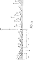
- Fig. 1a and 1b show a circular Fresnel mirror with a round, flat support member 10.
- a Fresnel structure 20 is arranged at the top of the support member 10.
- the angle of attack ⁇ of the support member 10 is 90 ° in this embodiment. This angle of attack ⁇ can also be less than 90 °. In this case, the support part 10 would be inclined to the imaginary vertical between focus F and center of the support member 10.
- the Fresnel structure 20 has annular concentric steps 21 1 , 21 2 , 21 3 to 21 n arranged around a center point.
- the carrier part 10 with the Fresnel structure 20 consists of a high-purity aluminum material and is made of an aluminum sheet produced by comparativwalzen.
- the surfaces of the individual stages 21 1 , 21 2 , 21 3 to 21 n represent the effective surfaces 31 1 , 31 2 , 31 3 to 31 n of the Fresnel mirror. Since this Fresnel mirror consists of a high-purity aluminum, an additional highly reflective coating of the active surfaces 31 1 , 31 2 , 31 3 to 31 n not necessary. Again Fig.
- the width of the steps x 1 , x 2 , x 3 to x n is at the in Fig. 1a and 1b shown Fresnel mirror the same size.
- the width x 1 , x 2 , x 3 to x n of the stages 21 1 , 21 2 , 21 3 to 21 n can also be selected to be of different sizes. It is more important that the angle of attack ⁇ 1 , ⁇ 2 , ⁇ 3 to ⁇ n of the active surfaces 31 1 , 31 2 , 31 3 to 31 n increases from the center of the Fresnel structure 20 to the outside, ie the angle of attack ⁇ 1 is the smallest angle, the angle of attack ⁇ n is the largest angle.
- the stage 21 1 has an effective area 31 1 , which is aligned significantly flatter than the effective area 31 n of the stage 21 n .
- the width a n of the outer step 31 n is greater than the width a 1 of the inner annular step 31 1 .
- the active surfaces 31 1 , 31 2 , 31 3 to 31 n are shown in the examples as flat surfaces. They can also be concave.
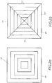
- the Fig. 2a and 2b also show a Fresnel mirror, which focuses the sun's rays on a focus F.
- a section through the Fresnel mirror according to Fig. 2a or 2b is similar to the sectional view in Fig. 1b ,
- the fresnel mirror in the Fig. 2a and 2b are square, ie all stages 22 of this Fresnel structure 20 have a square perimeter. It is also an embodiment of the Fresnel structure with rectangular steps possible.
- a Fresnel mirror is shown in which the Fresnel structure 20 is similar to the embodiment of FIG Fig. 1a , is formed at the top of the support member 10, namely by clutch rollers of an aluminum sheet.
- the same structure is obtained when four sheet metal sections 11, 11 ', 11 ", 11"' are assembled into a Fresnel mirror, as in Fig. 2b shown.
- extruded profile sections can be assembled into a square Fresnel mirror. In this way, the size of a Fresnel mirror can be increased, without larger forming devices are necessary in the production.
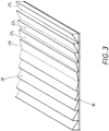
- a Fresnel mirror is shown with a rectangular base of the support member 10.
- the Fresnel structure 20 At the top of the support member 10 is the Fresnel structure 20, the parallel aligned stages 23 1 , 23 2 , 23 3 to 23 n has.
- a cross section through this Fresnel mirror is similar to the sectional view in FIG Fig. 1b ,
- a focus line At a distance f, ie at a distance of the focal length, there is a focus line, in this case away from the center line of the Fresnel mirror.
- solar cells can be provided for energy or an absorber tube can be arranged.
- the in Fig. 3 shown Fresnel mirror has been made of an aluminum sheet by constructively.
- Fig. 4 shows a collector unit 40 with a central profile 41.
- profiles 12, 12 ' are each provided in a symmetrical arrangement.
- the profiles 12, 12 ' have been produced by extrusion.
- a Fresnel structure 20 is provided on the upper side.
- the Fresnel mirror sufficient Give stability and can also serve as mounting elements. Furthermore, when extruding on the narrow sides of the support member 10 connecting means 13, 14 are formed.
- the profile 12 has connecting means 13, which have the shape of a sliding block, which can engage in a form-fitting manner in a corresponding undercut groove 14 of the profile 12 '.
- Such a positive connection 13, 14 is also provided to the central profile 41 so that the parts of the collector unit 40 can be assembled in a simple manner.
- the steps 23 1 , 23 2 , 23 3 to 23 n of the profiles 12, 12 ' have the same width and with increasing distance from the central profile 41 a rising angle of attack, comparable to the sectional view in FIG Fig. 1b , It would also be an embodiment with variable width and / or height of the steps possible. So that the active surfaces 30 are fully utilized in their width a, an undercut 26 or 27 is provided in the profiles 12 and 12 'at the back of each step 23 1 , 23 2 , 23 3 to 23 n .
- the undercut 26 shown in the steps of the profile 12 represents a concave indentation.
- the undercut 27 in the profile 12 ' is also a concave indentation, in this case, the indentation in height of the step beginning 24 is particularly strong.
- a collector tube 42 is provided in this embodiment.
- This collector tube 42 has an interior 43, which is traversed, for example, by water or another medium.
- the reflected from the Fresnel mirror sun rays heat the collector tube 42 and thus also the medium flowing through.
- this collector tube 42 is colored dark on its outside, for example by Painting or by powder coating.
- the inwardly directed ribs of the collector tube 42 contribute to a better heat transfer.
- This collector tube 42 is part of the central profile 41 and is located in this example at the upper end of a support bar 44.
- the collector tube 42 When connecting the collector tube 42 as low as possible heat transfer into the adjacent structure should be sought.
- the collector tube 42 can also be designed as a separate component.
- the support web 44 may be provided from a poorly heat-conductive material or connected by means of a connecting element made of poor thermal conductivity material with the collector tube 42.
- side bars 45, 46 From this support bar 44 protrude laterally in the lower area two side bars 45, 46 from. At the end of the side bars 45, 46 connecting means 14 are provided for the connection of the profiles 12, 12 '. In other embodiments, not shown, the side bars 45, 46 may be configured with active surfaces for the Fresnel structure.
- Fresnel mirror according to the invention are conceivable, which can be combined with solar cells for the production of electrical energy or in combination with collector tubes for heat energy recovery.
- the Fresnel mirrors were made of patterned aluminum sheet or extruded aluminum profiles in one piece or as segments of the Fresnel mirror.
Landscapes
- Engineering & Computer Science (AREA)
- Mechanical Engineering (AREA)
- Physics & Mathematics (AREA)
- General Engineering & Computer Science (AREA)
- Chemical & Material Sciences (AREA)
- Life Sciences & Earth Sciences (AREA)
- Sustainable Development (AREA)
- Sustainable Energy (AREA)
- Thermal Sciences (AREA)
- Combustion & Propulsion (AREA)
- Optics & Photonics (AREA)
- General Physics & Mathematics (AREA)
- Optical Elements Other Than Lenses (AREA)
Description
- Die Erfindung betrifft einen Fresnel-Spiegel zur gerichteten Reflexion von Licht, insbesondere von Sonnenlicht und/oder zur Lenkung von Kunstlicht in Beleuchtungssystemen, sowie ein Verfahren zur Herstellung eines solchen Fresnel-Spiegels.
- Bekannt ist eine Fresnel-Linse, die einen stufenförmigen Querschnitt aufweist und ursprünglich für Leuchttürme entwickelt wurde. Die Fresnel-Stufenlinse ermöglicht die Konstruktion großer Linsen mit kurzen Brennweiten, ohne das Gewicht und Volumen herkömmlicher Linsen, da billige Fresnel-Linsen auch aus Kunststoff hergestellt werden können. Typische Probleme von Kunststofflinsen sind Leistungsverluste durch Umwelteinflüsse und mechanische Beschädigungen aufgrund von Durchbiegungen sowie durch Temperaturbeanspruchung.
- Die Anwendung des Fresnel-Prinzips ist auch aus der
DE 102 48 064 bekannt. In dieser Offenlegungsschrift wird ein Solarturmkraftwerk gezeigt. Das Sonnenlicht wird durch ein Heliostatenfeld reflektiert und in einem Turmabsorber konzentriert und absorbiert. Das Heliostatenfeld besteht aus mehreren einzelnen Spiegeln, die nach dem Fresnel-Prinzip aufgestellt sind. Dieses Heliostatenfeld reflektiert das Sonnenlicht unabhängig von der Änderung der Sonnenposition am Himmel immer auf den gleichen ortsfesten Punkt. Nachteilig ist der Leistungsverlust durch die lange Brennweite. - In dem amerikanischen Patent
US 4 131 336 ist des Weiteren ein großer linearer Reflektor zur Gewinnung von Solarenergie gezeigt. Die Fresnel-Struktur ist hier in einem geformten und stabilisierten Erdboden eingebracht und die Reflexion wird über auf den Erdboden aufgebrachte, mit Aluminium beschichtete Polymerfolien ermöglicht. Nachteilig bei dieser Fresnel-Struktur ist der hohe Leistungsverlust aufgrund des hohen Anteils an ungerichteter Reflexion. - Nachteilig bei den vorgenannten Anwendungen sind der große Aufwand und die Baugrößen zur Erzielung der reflektierenden Struktur, was eine breite Anwendung verhindert.
- Aufgabe der vorliegenden Erfindung ist es daher, eine einfache Fresnel-Struktur zur Verfügung zu stellen, die leicht und automatisiert herstellbar ist und zur breiten Anwendung bei der Nutzung von Solarenergie oder als Reflektor in der Beleuchtungsindustrie eingesetzt werden kann.
- Diese Aufgabe wird mit einem Fresnel-Spiegel mit den Merkmalen des Anspruchs 1 gelöst.
- Bei dem erfindungsgemäßen Fresnel-Spiegel zur gerichteten Reflexion von Licht handelt es sich um ein im wesentlichen flaches Trägerteil im Gegensatz zu bekannten Parabolspiegeln. Dieses Trägerteil besitzt an seiner Oberseite eine Fresnel-Struktur und die einzelnen Stufen der Fresnel-Struktur weisen eine reflektierende Oberfläche als Wirkfläche auf.
- Das Trägerteil als Basisteil des Fresnel-Spiegels ist bei einer Ausführungsvariante mit einem weiteren Bauteil, welches als Fresnel-Struktur geformt ist, fest verbunden oder aber das Trägerteil als Basisteil ist bei einer weiteren Ausführungsform einstückig mit der Fresnel-Struktur ausgebildet. Im letzteren Fall bestehen also das Trägerteil und die Fresnel-Struktur aus ein und demselben Werkstoff bzw. Werkstück, wobei die Fresnel-Struktur vorzugsweise in das Basisteil eingeformt ist.
- Das Trägerteil besteht aus Metall, Kunststoff oder einem anderen geeigneten Werkstoff. Ein Trägerteil aus Kunststoff oder Metall, welches durch Spritzgießen hergestellt wird, kann bei der Herstellung leicht mit einer Fresnel-Struktur versehen werden. Ein solchermaßen gefertigtes Trägerteil mit der eingeformten Fresnel-Struktur muss jedoch mit einer reflektierenden Oberfläche versehen werden, beispielsweise durch Beschichten der Stufen der Fresnel-Struktur mit einer Silberschicht, mit einer hochreinen Aluminiumschicht oder einer anderen geeigneten Beschichtung.
- Bei einer weiteren Ausführungsform besteht das Trägerteil des Fresnel-Spiegels aus Metallblech. In das Trägerteil aus Metall lässt sich durch Umformen eine Fresnel-Struktur einbringen. Bei einer bevorzugten Ausführungsform wird für das Metallträgerteil ein Edelstahl- oder Aluminiumblech verwendet. Das Einbringen der Fresnel-Struktur kann in diesem Fall in einfacher Weise durch Dessinieren, Prägen, Walzen, Tiefziehen, Hydroformen bzw. Floatformen erfolgen.
- Bei der erfindungsgemäßen Ausführungsform besteht das Trägerteil des Fresnel-Spiegels ebenfalls aus Aluminium oder einer AluminiumLegierung und wird durch Strangpressen hergestellt. Beim Strangpressen des Trägerteils wird gleichzeitig auch die Fresnel-Struktur geformt.
- Besitzt das Metall des Trägerteils und damit die Fresnel-Struktur bereits eine hohe Reflexion, so kann auf eine zusätzliche Beschichtung der als Wirkfläche dienenden Stufen der Fresnel-Struktur verzichtet werden. Anderenfalls kann zusätzlich auf die Stufen der Fresnel-Struktur eine hochreflektierende Schicht aufgebracht werden.
- Je nach Anwendungsfall, beispielsweise bei einem Einsatz des Fresnel-Spiegels im Außenbereich, wo der Fresnel-Spiegel Witterungseinflüssen ausgesetzt ist, wird die als Wirkfläche fungierende reflektierende Oberfläche der Fresnel-Struktur zusätzlich mit einer witterungsbeständigen Schutzschicht versehen. Eine solche Schutzschicht kann eine geeignete, dünne, durchsichtige Lackschicht sein. Bei der Verwendung von Aluminium zur Herstellung des Fresnel-Spiegels, insbesondere aus einer Aluminiumlegierung mit sehr hohem Aluminiumanteil, die eine ausreichende Reflexion für die reflektierende Oberfläche der Fresnel-Struktur besitzt, kann die witterungsbeständige Schutzschicht durch Anodisieren und Verdichten des Aluminiummaterials erzielt werden.
- Wie bei bekannten Sonnenlichtabsorbern lässt sich ein solcher gegebenenfalls mit Nachführungssystemen ausgestatteter Fresnel-Spiegel dazu einsetzen, das Sonnenlicht auf einen ortsfesten Punkt oder eine Linie zu reflektieren. In dem Fall, wo eine Reflektion auf einen ortsfesten Punkt erfolgt, weist die Fresnel-Struktur des Fresnel-Spiegels ringförmige Stufen auf, die eine konzentrische Struktur ergeben. An dem ortsfesten Punkt, an dem die vom Fresnel-Spiegel reflektierten Sonnenlichtstrahlen zusammentreffen, kann zum Aufbau eines Solarkollektors eine Solarzelle angeordnet werden. Diese Solarzelle wandelt die aus dem Sonnenlicht gewonnene Strahlungsenergie direkt in elektrische Energie um und leitet diese Energie zur Nutzung an entsprechende Verbraucher weiter. Eine alternative Ausführungsform des Fresnel-Spiegels besitzt quadratische, welche ebenfalls konzentrisch angeordnet sind und das Sonnenlicht auf einen ortsfesten Punkt (Fokus) hin reflektieren. Eine alternative Ausführungsform des Fresnel-Spiegels besitzt rechteckige Stufen. Die quadratische und rechteckige Ausführungsform hat den Vorteil, dass eine bessere Materialausnutzung stattfindet und damit der bei der Herstellung des Fresnel-Spiegels anfallende Abfall reduziert wird. Ebenfalls ist eine Effizienzsteigerung durch die Anpassung des rechteckigen Fokus an die Geometrie der Solarzelle möglich. Eine metallische konzentrische Fresnel-Struktur wird bevorzugt aus einem Metallblech gebildet. Möglich ist es auch eine konzentrische Struktur aus mehreren Abschnitten eines Metallbleches oder mehreren Abschnitten eines Strangpressprofils zusammen zu setzen. In diesem Fall können insbesondere auch größer dimensionierte Fresnel-Spiegel gebildet werden.
- In der erfindungsgemäßen Ausführungsform eines Fresnel-Spiegels wird das Sonnenlicht auf eine ortsfeste Linie reflektiert. In diesem Fall weist die Fresnel-Struktur parallel zueinander ausgerichtete Stufen auf. Ein solcher Fresnel-Spiegel reflektiert das Sonnenlicht beispielsweise auf eine Linie, an der sich ein Absorberrohr befinden kann, das die Energie des Sonnenlichtes in Wärmeenergie, beispielsweise zur Dampferzeugung, umwandelt. An der vorgenannten Linie können auch Solarzellen zur Energiegewinnung aneinander gereiht vorgesehen werden. Ein Fresnel-Spiegel mit einer metallischen Fresnel-Struktur mit parallel ausgerichteten Stufen wird bevorzugt aus einem Strangpressteil gebildet. Er kann auch aus mehreren miteinander verbundenen Strangpressprofilen bestehen, wobei beim Strangpressen in vorteilhafter Weise gleichzeitig die Verbindungsmittel an den Profilen erzeugt werden.
- Die vorbeschriebenen Fresnel-Spiegel lassen sich über verschiedene Verfahren herstellen. Ist das Trägerteil des Fresnel-Spiegels aus einem Metallmaterial, insbesondere einem Stahl- oder einem Aluminiumblech, so werden zwei alternative Verfahren zur Herstellung vorgeschlagen.
- Bei einem möglichen Verfahren wird das aufgewickelte Metallblech in Blechplatinen zugeschnitten, die die entsprechende Größe und Form des gewünschten Fresnel-Spiegels aufweisen. Bedarfsweise kann eine etwas größere Form gewählt werden und der Überstand nach dem Umformen entfernt oder für Befestigungsteile vorgesehen werden. Die zugeschnittene, als Trägerteil dienende Blechplatine wird in eine Umformvorrichtung zwischen zwei Werkzeughälften eingelegt, wobei die eine Werkzeughälfte eine Negativform der gewünschten Fresnel-Struktur aufweist. Durch den Umformvorgang wird die Fresnel-Struktur in die Blechplatine eingeformt. Bei einem solchen Umformen kann es sich um Prägen, um Floatforming, Tiefziehen oder ein anderes Hydroformingverfahren handeln. Bei großen Umformvorrichtungen oder kleinen Fresnel-Spiegeln kann die Werkzeughälfte auch mehr als eine Negativform der Fresnel-Struktur aufweisen, so dass gleichzeitig mehrere Blechplatinen mit je einer Fresnel-Struktur versehen werden. In diesem Fall wird vorzugsweise eine große Blechplatine in die Umformvorrichtung eingelegt und nach dem Umformen die Blechplatine aufgeteilt und zugeschnitten, so dass die einzelnen Fresnel-Spiegel entstehen.
- Zur Herstellung größerer Fresnel-Spiegel können die Wirkflächen auch segmentiert und aus mehreren Teilflächen zusammengesetzt werden.
- Bei einer alternativen Verfahrensweise wird das Metallblech direkt vom Coil in eine Dessinwalzvorrichtung eingeführt. Die Dessinwalze besitzt zur Erzeugung der Fresnel-Struktur mindestens eine Negativform der gewünschten Fresnel-Struktur. Es können jedoch auch benachbart, sowohl nebeneinander als auch hintereinander, mehrere Fresnel-Strukturen auf der Dessinwalze vorgesehen sein. Besondere Vorteile hat ein solches Umformverfahren auch, wenn Fresnel-Spiegel erzeugt werden, die parallel zueinander ausgerichtete Stufen aufweisen, um das Sonnenlicht auf eine ortsfeste Linie zu reflektieren. Das Einformen der Fresnel-Struktur in die als Trägerteil dienende Blechplatine erfolgt während des Dessinwalzens, anschließend wird das dessinierte Blechband auf die entsprechende Größe und Form des gewünschten Fresnel-Spiegels zugeschnitten. Bei diesem Verfahren ist das Metallblech vorzugsweise ein Aluminiumblech.
- Eine weitere alternative und vorteilhafte Verfahrensweise zur Herstellung eines Fresnel-Spiegels erfolgt durch Strangpressen. Ein Metallbarren, insbesondere aus Aluminium oder einer Aluminium-Legierung, wird in der Strangpresse zu einem Profilstrang umgeformt. Nachfolgend erfolgt - wie auch für andere Profilgeometrien bekannt - ein Abschrecken und Recken des Profilstranges, wobei der Abschreckvorgang abhängig ist von der eingesetzten Legierung. Von diesem Profilstrang werden entsprechend der Länge des gewünschten Fresnel-Spiegels gewünschte Teillängen abgetrennt. Der beim Strangpressen entstehende Profilquerschnitt des Profilstranges umfasst das Trägerteil mit der Fresnel-Struktur auf einer Breitseite, der Oberseite, des Trägerteiles. Vorteilhafter Weise können gleichzeitig während des Strangpressens des Trägerteils Verbindungselemente, Verstärkungen und Montageelemente als Teile des Gesamtprofils erzeugt werden. Bei einer besonderen Ausführungsform werden an den Schmalseiten des Trägerteiles Verbindungselemente vorgesehen, die eine formschlüssige Verbindung der Profile mit Fresnel-Struktur untereinander und/oder mit anderen Bauteilen ermöglichen. Auf diese Weise ist eine Vergrößerung der wirksamen Fläche eines Fresnel-Spiegels möglich. Ebenso können die Profile auch mit einem Zentralprofil verbunden werden, welches beispielsweise ein Kollektorrohr umfasst, das in der Brennlinie der zu einem Fresnel-Spiegel zusammengesetzten Profile liegt.
- In dem Fall, wo ein Blech aus hochreflektierendem Edelstahl bzw. aus Aluminium und/oder aus einer Aluminiumlegierung mit sehr hohen Aluminiumanteilen verwendet wird, , braucht keine zusätzlich reflektierende Schicht auf die Fresnel-Struktur aufgebracht werden. Zur Erzeugung einer hochglänzenden, hochreflektierenden Oberfläche wird dazu bei einer bevorzugten Ausführungsform das Metallblech vor dem Umformen gereinigt, entfettet und/oder gebeizt. Des Weiteren kann vor dem Umformen oder nach dem Umformen ein Polierverfahren und/oder ein Glänzverfahren bei einem Aluminiumlegierungsblech vorgesehen werden. Die empfindliche Aluminiumschicht wird durch Anodisieren und Verdichten geschützt. Beim Verdichten kann es sich um Kalt- und/oder Heißverdichten handeln. Das gleiche Behandlungsverfahren ist auch auf Fresnel-Spiegel aus einem Strangpressprofil aus Aluminium oder einer Aluminium-Legierung anwendbar.
- Wird bei den vorgenannten Verfahren ein Metallblech mit nicht ausreichender Reflexionsfähigkeit eingesetzt, so kann nach dem Umformen zusätzlich eine hochreflektierende Schicht aufgebracht werden. Bei einer solchen Schicht handelt es sich vorzugsweise um Silber oder um eine Schicht aus einem hochreinen Aluminium. Eine solche zusätzliche Schicht kann auch bei einem Fresnel-Spiegel vorgesehen werden, dessen Trägerteil aus einem Spritzgussteil aus Kunststoff oder Metall besteht. In diesem Fall wird das Trägerteil zusammen mit der Fresnel-Struktur einstückig in einer Spritzgussvorrichtung hergestellt und anschließend die Stufen der Fresnel-Struktur mit der hochreflektierenden Schicht beschichtet.
- Abhängig vom Anwendungsfall kann die Oberfläche des Fresnel-Spiegels zusätzlich mit einer witterungsbeständigen Schutzschicht versehen werden. Diese witterungs-beständige Schutzschicht muss jedoch durchsichtig sein und sollte eine geringe Dicke aufweisen.
- Durch alle vorgenannten alternativen Verfahren ist ein Fresnel-Spiegel leicht und automatisiert herstellbar und eignet sich somit zur breiten Anwendung bei der Nutzung von Solarenergie.
- Weitere Einzelheiten der Erfindung sind der folgenden Beschreibung von Ausführungsbeispielen der Erfindung anhand von Zeichnungen zu entnehmen. Es zeigen:
- Fig. 1a
- eine Draufsicht auf einen Fresnel-Spiegel;
- Fig.
- 1b eine Schnittdarstellung des Fresnel-Spiegels gemäß
Fig. 1a ; - Fig. 2a
- eine Draufsicht auf einen weiteren Fresnel-Spiegel;
- Fig. 2b
- eine Draufsicht auf einen weiteren Fresnel-Spiegel;
- Fig. 3
- perspektivische Ansicht eines weiteren Fresnel-Spiegels;
- Fig. 4
- Ausschnitt aus einer erfindungsgemäßen Kollektoreinheit in Schnittdarstellung.
-
Fig. 1a und1b zeigen einen kreisförmigen Fresnel-Spiegel mit einem runden, flachen Trägerteil 10. An der Oberseite des Trägerteils 10 ist eine Fresnel-Struktur 20 angeordnet. Der Anstellwinkel β des Trägerteils 10 beträgt bei dieser Ausführung 90°. Dieser Anstellwinkel β kann auch kleiner als 90° sein. In diesem Fall wäre das Trägerteil 10 zur gedachten Lotrechten zwischen Fokus F und Mittelpunkt des Trägerteils 10 geneigt. - Die Fresnel-Struktur 20 besitzt ringförmige, um einen Mittelpunkt angeordnete konzentrische Stufen 211, 212, 213 bis 21n. Das Trägerteil 10 mit der Fresnel-Struktur 20 besteht aus einem hochreinen Aluminiumwerkstoff und ist aus einem Aluminiumblech durch Dessinwalzen hergestellt worden. Die Oberflächen der einzelnen Stufen 211, 212, 213 bis 21n stellen die Wirkflächen 311, 312, 313 bis 31n des Fresnel-Spiegels dar. Da dieser Fresnel-Spiegel aus einem hochreinen Aluminium besteht, ist eine zusätzliche hochreflektierende Beschichtung der Wirkflächen 311, 312, 313 bis 31n nicht notwendig. Wie der
Fig. 1b zu entnehmen ist, werden Sonnenstrahlen - nicht gezeigt - die auf diesen Fresnel-Spiegel fallen von den Wirkflächen 311, 312, 313 bis 31n auf einen Punkt reflektiert, dem Fokus F, der sich in einer Brennweite f vom Mittelpunkt der konzentrischen Fresnel-Struktur 20 entfernt befindet. Zur Energiegewinnung aus Sonnenlicht kann in diesem Punkt F eine Solarzelle angeordnet werden. Durch eine geeignete Wahl der Winkel α1, α2, α3 bis αn der Wirkflächen 311, 312, 313 bis 31n kann auch ein außenmittiger Fokus erreicht werden. - Die Breite der Stufen x1, x2, x3 bis xn ist bei dem in
Fig. 1a und1b gezeigten Fresnel-Spiegel gleich groß. Die Breite x1, x2, x3 bis xn der Stufen 211, 212, 213 bis 21n kann jedoch auch unterschiedlich groß gewählt werden. Wesentlicher ist, dass der Anstellwinkel α1, α2, α3 bis αn der Wirkflächen 311, 312, 313 bis 31n sich vom Mittelpunkt der Fresnel-Struktur 20 nach außen hin vergrößert, d.h. der Anstellwinkel α1 ist der kleinste Winkel, der Anstellwinkel αn ist der größte Winkel. Dies bedeutet, dass die Stufe 211 eine Wirkfläche 311 hat, die bedeutend flacher ausgerichtet ist, als die Wirkfläche 31n der Stufe 21n. Damit ist auch die Breite an der äußeren Stufe 31n größer als die Breite a1 der inneren ringförmigen Stufe 311. Die Wirkflächen 311, 312, 313 bis 31n sind in dem Beispielen als ebene Flächen dargestellt. Sie können auch konkav gewölbt sein. - Die
Fig. 2a und 2b zeigen ebenfalls einen Fresnel-Spiegel, der die Sonnenstrahlen auf einen Fokus F konzentriert. Ein Schnitt durch den Fresnel-Spiegel gemäßFig. 2a bzw. 2b ist vergleichbar mit der Schnittdarstellung inFig. 1b . Die Fresnel-Spiegel in denFig. 2a und 2b sind jedoch quadratisch, d.h. alle Stufen 22 dieser Fresnel-Struktur 20 haben eine quadratische Umfangslinie. Es ist auch eine Ausgestaltung der Fresnel-Struktur mit rechteckigen Stufen möglich. - In der
Fig. 2a ist ein Fresnel-Spiegel gezeigt, bei dem die Fresnel-Struktur 20, ähnlich wie bei der Ausführungsform gemäßFig. 1a , an der Oberseite des Trägerteils 10 eingeformt ist, nämlich durch Dessinwalzen eines Aluminiumbleches. Die gleiche Struktur erhält man, wenn man vier Blechabschnitte 11, 11', 11", 11"' zu einem Fresnel-Spiegel zusammensetzt, wie inFig. 2b gezeigt. In gleicher Weise können anstatt der Blechabschnitte 11, 11', 11", 11"' auch stranggepresste Profilabschnitte zu einem quadratischen Fresnel-Spiegel zusammengesetzt werden. Auf diese Weise kann die Baugröße eines Fresnel-Spiegels vergrößert werden, ohne dass größere Umformvorrichtungen bei der Herstellung notwendig sind. - In der
Fig. 3 wird ein Fresnel-Spiegel mit einer rechteckigen Grundfläche des Trägerteils 10 gezeigt. An der Oberseite des Trägerteils 10 befindet sich die Fresnel-Struktur 20, die parallel zueinander ausgerichtete Stufen 231, 232, 233 bis 23n besitzt. Ein Querschnitt durch diesen Fresnel-Spiegel ähnelt der Schnittdarstellung inFig. 1b . Im Abstand f, also im Abstand der Brennweite, befindet sich, in diesem Fall von der Mittellinie des Fresnel-Spiegels entfernt, also eine Fokuslinie. Entlang dieser Fokuslinie können Solarzellen zur Energiegewinnung vorgesehen oder aber ein Absorberrohr angeordnet werden. Der inFig. 3 gezeigte Fresnel-Spiegel ist aus einem Aluminiumblech durch Dessinwalzen gefertigt worden. -
Fig. 4 zeigt eine Kollektoreinheit 40 mit einem Zentralprofil 41. Beidseitig von diesem Zentralprofil 41 sind jeweils in symmetrischer Anordnung Profile 12, 12' vorgesehen. Diese Profile 12, 12' ergänzen sich in ihrer zusammengesetzten Form zu einem Fresnel-Spiegel. Die Profile 12, 12' sind durch Strangpressen erzeugt worden. An dem flachen Trägerteil 10 der zusammengesetzten Profile 12, 12' ist auf der Oberseite eine Fresnel-Struktur 20 vorhanden. Diese Profile 12, 12' sind als Vollprofile gepresst. Es ist zur Materialeinsparung auch möglich diese als Hohlprofile auszugestalten, so dass zwischen dem Trägerteil 10 und den Wirkflächen 30 der Stufen der Fresnel-Struktur 20 Hohlräume vorgesehen werden. An der Unterseite des Trägerteils 10 sind Verstärkungsstege 15 angeformt, die dem Fresnel-Spiegel eine ausreichende Stabilität geben und auch als Montageelemente dienen können. Des Weiteren sind beim Strangpressen an den Schmalseiten des Trägerteils 10 Verbindungsmittel 13, 14 angeformt. In diesem Fall besitzt das Profil 12 Verbindungsmittel 13, die die Form eines Nutsteins aufweisen, der in eine entsprechende hinterschnittene Nut 14 des Profils 12' formschlüssig eingreifen kann. Eine solche formschlüssige Verbindung 13, 14 ist auch zum Zentralprofil 41 vorgesehen, so dass sich die Teile der Kollektoreinheit 40 in einfacher Weise zusammenfügen lassen. - Die Stufen 231, 232, 233 bis 23n der Profile 12, 12' weisen die gleiche Breite auf und mit steigender Entfernung vom Zentralprofil 41 einen ansteigenden Anstellwinkel, vergleichbar mit der Schnittdarstellung in
Fig. 1b . Es wäre auch eine Ausgestaltung mit veränderlicher Breite und/oder Höhe der Stufen möglich. Damit die Wirkflächen 30 in ihrer Breite a vollständig ausgenutzt werden, wird bei den Profilen 12 und 12' an der Rückseite jeder Stufe 231, 232, 233 bis 23n ein Hinterschnitt 26 bzw. 27 vorgesehen. Der gezeigte Hinterschnitt 26 bei den Stufen des Profils 12 stellt eine konkave Einbauchung dar. Der Hinterschnitt 27 beim Profil 12' ist ebenfalls eine konkave Einbauchung, in diesem Fall ist die Einbauchung in Höhe des Stufenanfanges 24 besonders stark. Durch das Vorsehen dieser Hinterschnitte 26, 27 auf den Rückseiten der Stufen 231, 232, 233 bis 23n der Profile 12, 12' wird beim Herstellen durch Strangpressen verhindert, dass durch Grate oder erforderliche Mindestradien beim Strangpressen im Bereich des Stufenanfanges 24 oder des Stufenendes 25 die Wirkflächen 30 verkleinert werden. - Die von dem durch die Profile 12, 12' gebildeten Fresnel-Spiegel reflektierten Sonnenstrahlen treffen auf eine Fokuslinie. Entlang dieser Fokuslinie ist in diesem Ausführungsbeispiel ein Kollektorrohr 42 vorgesehen. Dieses Kollektorrohr 42 besitzt einen Innenraum 43, der beispielsweise von Wasser oder einem anderen Medium durchflossen wird. Die von dem Fresnel-Spiegel reflektierten Sonnenstrahlen erwärmen das Kollektorrohr 42 und damit auch die durchfließende Medium. Für einen besseren Wärmeübergang ist dieses Kollektorrohr 42 an seiner Außenseite dunkel eingefärbt, beispielsweise durch Lackieren oder durch Pulverbeschichten. In gleicher Weise tragen die nach innen weisenden Rippen des Kollektorrohres 42 zu einer besseren Wärmeübertragung bei. Dieses Kollektorrohr 42 ist Teil des Zentralprofils 41 und befindet sich in diesem Beispiel am oberen Ende eines Tragsteges 44. Bei der Anbindung des Kollektorrohres 42 ist ein möglichst geringer Wärmeübergang in die benachbarte Struktur anzustreben. Das Kollektorrohr 42 kann auch als separates Bauteil ausgeführt werden. Auch kann der Tragsteg 44 aus einem schlecht wärmeleitenden Material vorgesehen sein oder mittels eines aus schlecht wärmeleitenden Material hergestellten Verbindungselement mit dem Kollektorrohr 42 verbunden.
- Von diesem Tragsteg 44 ragen im unteren Bereich seitlich zwei Seitenstege 45, 46 ab. Endseitig an den Seitenstegen 45, 46 sind Verbindungsmittel 14 vorgesehen für den Anschluss der Profile 12, 12'. Bei weiteren nicht gezeigten Ausführungen können auch die Seitenstege 45, 46 mit Wirkflächen für die Fresnel-Struktur ausgestaltet sein.
- Die Erfindung ist nicht auf die gezeigten Ausführungsbeispiele beschränkt. Es sind vielmehr weitere Ausführungsformen eines erfindungsgemäßen Fresnel-Spiegels denkbar, der kombiniert mit Solarzellen zur Gewinnung von elektrischer Energie oder in Verbindung mit Kollektorrohren zur Wärmeenergiegewinnung kombiniert werden kann. In den Ausführungsbeispielen wurden die Fresnel-Spiegel aus durch Dessinwalzen geformten Aluminiumblech oder Aluminium-Strangpressprofilen einstückig oder als Segmente des Fresnel-Spiegels hergestellt. Es ist jedoch auch denkbar die Fresnel-Struktur separat zu fertigen und mit einem Trägerteil zu verbinden.
-
- 10
- Trägerteil
- 11,11',11",11"'
- Blechabschnitt
- 12,12'
- Profil
- 13, 14
- Verbindungsmittel
- 15
- Verstärkungssteg
- 20
- Fresnel-Struktur
- 211,212,213,21n
- Stufe einer konzentrischen Fresnel-Struktur
- 22
- Stufe einer quadratischen Fresnel-Struktur
- 231,232,233,23n
- Stufe einer rechteckigen Fresnel-Struktur
- 24
- Stufenanfang
- 25
- Stufenende
- 26
- Hinterschnitt
- 27
- Hinterschnitt
- 30
- Wirkfläche
- 311,312,313,31n
- Wirkfläche der Stufen 211,212,213,21n
- 40
- Kollektoreinheit
- 41
- Zentralprofil
- 42
- Kollektorrohr
- 43
- Innenraum
- 44
- Tragsteg
- 45, 46
- Seitensteg
- a,a1,a2,a3,an
- Breite der Wirkfläche von 211,212,213,21n
- x1,x2,x3,xn
- Breite der Stufe 211,212,213,21n
- α1, α2, α3, αn
- Anstellwinkel der Wirkflächen 311,312,313,31n
- β
- Anstellwinkel des Trägerteils 10
- f
- Brennweite
- F
- Fokus
Claims (5)
- Fresnel-Spiegel aus einem flachem Trägerteil (10), welches an seiner Oberseite eine Fresnel-Struktur (20) besitzt, wobei zur gerichteten Reflexion von Sonnenlicht auf einen Fokuspunkt oder auf eine Fokuslinie die einzelnen Stufen (21; 22; 23) dieser Fresnel-Struktur (20) eine reflektierende, ebene Oberfläche als Wirkfläche (30) aufweisen,
wobei diese eine Fresnel-Struktur (20) aus mehreren durch Strangpressen erzeugten Profilen (12, 12', 12") aus Aluminium oder einer Aluminium-Legierung zusammengesetzt ist,
dadurch gekennzeichnet,
dass an den Profilen (12, 12', 12") Verbindungsmittel (13, 14) angeformt sind, die der formschlüssigen Verbindung der Profile (12, 12', 12") untereinander dienen und sich die Profile (12, 12', 12") in ihrer zusammengesetzten Form zu der einer Fresnel-Struktur (20) ergänzen,
dass diese eine Fresnel-Struktur (20), so aus den Profilen (12, 12', 12") zusammengesetzt ist, dass sich eine gerichtete Reflexion von Sonnenlicht auf eine gemeinsame Fokuslinie (42) ergibt. - Fresnel-Spiegel nach Anspruch 1, wobei die an den Profilen (12, 12', 12") angeformten Verbindungsmittel (13, 14) zusätzlich zur Verbindung mit weiteren Bauteilen dienen.
- Fresnel-Spiegel nach Anspruch 1, wobei das Trägerteil (10) als Basisteil und die Fresnel-Struktur (20) aus einem Werkstoff bestehen, wobei die Fresnel-Struktur (20) in das Basisteil eingeformt ist und die Wirkfläche (30) der Fresnel-Struktur (20) durch das Metall des Trägerteils (10) gebildet wird.
- Fresnel-Spiegel nach einem der Ansprüche 1 bis 3 wobei der Fresnel-Spiegel zur Reflexion des Sonnenlichtes auf eine ortsfeste Linie die Fresnel-Struktur (20) parallel zueinander ausgerichtete Stufen (231,232,233,23n) aufweist.
- Kollektoreinheit (40) umfassend Fresnel-Spiegel gemäß einem oder mehreren der Ansprüche 1 bis 4 und ein Zentralprofil (41), wobei das Zentralprofil (41) zumindest ein entlang der Fokuslinie des Fresnel-Spiegels angeordnetes Kollektorrohr (42) enthält, welches am oberen Ende eines aufrecht stehenden Tragstegs (44) vorgesehen ist, wobei vom unteren Ende des Tragstegs (44) beidseitig Seitenstege (45, 46) abragen und die Seitenstege (45, 46) Verbindungsmittel (14) besitzen, die mit Verbindungsmitteln (13) von Blechabschnitten (11, 11', 11", 11''') oder von Profilen (12, 12', 12") der Fresnel-Struktur (20) des Fresnel-Spiegels zur Verbindungsbildung zusammenwirken.
Priority Applications (1)
| Application Number | Priority Date | Filing Date | Title |
|---|---|---|---|
| PL08861772T PL2223175T3 (pl) | 2007-12-17 | 2008-12-10 | Lustro fresnela |
Applications Claiming Priority (2)
| Application Number | Priority Date | Filing Date | Title |
|---|---|---|---|
| DE102007061153A DE102007061153A1 (de) | 2007-12-17 | 2007-12-17 | Fresnel-Spiegel und Verfahren zu dessen Herstellung |
| PCT/EP2008/010469 WO2009077112A1 (de) | 2007-12-17 | 2008-12-10 | Fresnel-spiegel und verfahren zu dessen herstellung |
Publications (2)
| Publication Number | Publication Date |
|---|---|
| EP2223175A1 EP2223175A1 (de) | 2010-09-01 |
| EP2223175B1 true EP2223175B1 (de) | 2017-02-22 |
Family
ID=40380440
Family Applications (1)
| Application Number | Title | Priority Date | Filing Date |
|---|---|---|---|
| EP08861772.5A Not-in-force EP2223175B1 (de) | 2007-12-17 | 2008-12-10 | Fresnel-spiegel |
Country Status (6)
| Country | Link |
|---|---|
| US (1) | US8292442B2 (de) |
| EP (1) | EP2223175B1 (de) |
| DE (1) | DE102007061153A1 (de) |
| ES (1) | ES2625688T3 (de) |
| PL (1) | PL2223175T3 (de) |
| WO (1) | WO2009077112A1 (de) |
Families Citing this family (16)
| Publication number | Priority date | Publication date | Assignee | Title |
|---|---|---|---|---|
| DE102007061153A1 (de) | 2007-12-17 | 2009-06-25 | Erbslöh Aluminium Gmbh | Fresnel-Spiegel und Verfahren zu dessen Herstellung |
| ES2364115B1 (es) * | 2009-12-30 | 2012-03-23 | Agengoa Solar New Technologies, S.A. | Colector solar cilindro paramétrico con reconcentrador secundario optimizado y su procedimiento de diseño. |
| EP2354715A1 (de) * | 2009-12-31 | 2011-08-10 | Universitat Jaume I | Sonnenkollektor |
| MA34164B1 (fr) * | 2010-04-22 | 2013-04-03 | Trevor Powell | Système collecteur d'énergie solaire |
| DE102011004266A1 (de) * | 2011-02-17 | 2012-08-23 | Siemens Aktiengesellschaft | Sonnenkollektor mit innenberippten Rohren |
| CN102566022B (zh) * | 2012-02-29 | 2014-06-18 | 陈应天 | 非近轴高次柱面组成的平板式反射聚光器 |
| CN103591703A (zh) * | 2012-08-14 | 2014-02-19 | 北京兆阳光热技术有限公司 | 一种太阳能聚集系统 |
| US20150293276A1 (en) * | 2012-10-24 | 2015-10-15 | Komy Co., Ltd. | Mirror for checking blind spot |
| DE102013019302B4 (de) | 2013-11-11 | 2015-07-09 | Met-Optik Elektronische Systeme Gmbh | Parabol-Stufenreflektor und Verfahren zur Herstellung und zum Justieren |
| US9987859B2 (en) | 2016-09-29 | 2018-06-05 | Ricoh Company, Ltd. | Reflectors for evenly heating a drum dryer of a print system |
| WO2018210331A1 (zh) * | 2017-05-18 | 2018-11-22 | 常州大学 | 一种两次点聚焦的太阳能收集装置 |
| US20200300508A1 (en) * | 2017-09-22 | 2020-09-24 | Trevor Powell | Coated solar reflector panel |
| WO2019246115A1 (en) | 2018-06-18 | 2019-12-26 | Magic Leap, Inc. | Rgb illuminator system having curved surfaces |
| GB2589818B (en) | 2019-07-12 | 2022-12-14 | De La Rue Int Ltd | Security devices and methods of manufacture thereof |
| GB2614024B (en) * | 2021-08-11 | 2024-04-03 | Solar Polar Ltd | Solar thermal collector |
| WO2026089331A1 (ko) * | 2024-10-25 | 2026-04-30 | 주식회사 케이시티 | 태양열 집열 장치 |
Family Cites Families (10)
| Publication number | Priority date | Publication date | Assignee | Title |
|---|---|---|---|---|
| US3058394A (en) * | 1959-06-26 | 1962-10-16 | Du Pont | Reflector for solar heaters |
| US3982527A (en) * | 1974-01-02 | 1976-09-28 | Cheng Chen Yen | Method and apparatus for concentrating, harvesting and storing of solar energy |
| US4131336A (en) | 1977-01-25 | 1978-12-26 | Nasa | Primary reflector for solar energy collection systems |
| US4222368A (en) * | 1977-12-22 | 1980-09-16 | General Extrusions, Inc. | Solar energy collection apparatus and system |
| US4301321A (en) * | 1980-08-11 | 1981-11-17 | Spectrolab | Two-axis focusing energy concentrator |
| JPS57122401A (en) * | 1981-01-22 | 1982-07-30 | Dainippon Printing Co Ltd | Flat-curved mirror and its manufacture |
| DE8622427U1 (de) * | 1986-08-21 | 1986-11-27 | Anderl, Rudolf, Dipl.-Phys., 7910 Neu-Ulm | Sonnenkollektor |
| US4784700A (en) * | 1987-05-26 | 1988-11-15 | General Dynamics Corp./Space Systems Div. | Point focus solar concentrator using reflector strips of various geometries to form primary and secondary reflectors |
| DE10248064B4 (de) | 2002-10-11 | 2007-11-22 | Deutsches Zentrum für Luft- und Raumfahrt e.V. | Solar-Receivervorrichtung zur solarthermischen Erhitzung eines Wärmeaufnahmemediums |
| DE102007061153A1 (de) | 2007-12-17 | 2009-06-25 | Erbslöh Aluminium Gmbh | Fresnel-Spiegel und Verfahren zu dessen Herstellung |
-
2007
- 2007-12-17 DE DE102007061153A patent/DE102007061153A1/de not_active Withdrawn
-
2008
- 2008-12-10 ES ES08861772.5T patent/ES2625688T3/es active Active
- 2008-12-10 EP EP08861772.5A patent/EP2223175B1/de not_active Not-in-force
- 2008-12-10 WO PCT/EP2008/010469 patent/WO2009077112A1/de not_active Ceased
- 2008-12-10 US US12/735,097 patent/US8292442B2/en not_active Expired - Fee Related
- 2008-12-10 PL PL08861772T patent/PL2223175T3/pl unknown
Non-Patent Citations (1)
| Title |
|---|
| None * |
Also Published As
| Publication number | Publication date |
|---|---|
| EP2223175A1 (de) | 2010-09-01 |
| US20100309569A1 (en) | 2010-12-09 |
| US8292442B2 (en) | 2012-10-23 |
| DE102007061153A1 (de) | 2009-06-25 |
| PL2223175T3 (pl) | 2017-08-31 |
| WO2009077112A1 (de) | 2009-06-25 |
| ES2625688T3 (es) | 2017-07-20 |
| WO2009077112A4 (de) | 2009-09-24 |
Similar Documents
| Publication | Publication Date | Title |
|---|---|---|
| EP2223175A1 (de) | Fresnel-spiegel und verfahren zu dessen herstellung | |
| DE2806545C2 (de) | Sonnenenergie-Kollektor | |
| EP2304334B1 (de) | Rinnenkollektor für ein solarkraftwerk | |
| EP0767889A1 (de) | Vorrichtung zur gewinnung von energie aus sonnenlicht mit mindestens einem solarkollektor | |
| DE102010034020A1 (de) | Oberflächenstruktur sowie Fresnel-Linse und Werkzeug zur Herstellung einer Oberflächenstruktur | |
| EP1099078B1 (de) | Optisches element zur umlenkung von lichtstrahlen und herstellungsverfahren | |
| WO2014118293A1 (de) | Parabolrinnenspiegel | |
| DE2933089A1 (de) | Sonnenwaermekollektor | |
| DE19709653C2 (de) | Hybridkollektor und Verfahren zum Herstellen eines Solarmoduls zum Einsatz in den Hybridkollektor | |
| DE202011050015U1 (de) | Solarkollektor | |
| DE4405650C1 (de) | Solarkraftwerk mit photovoltaischen, gekühlten Solarmodulen | |
| WO2015162077A1 (de) | Wärmeübertragungsvorrichtung, solarkollektor und wärmerohr | |
| DE102007047110B4 (de) | Wärmetauscher, insbesondere Absorber für thermische Solarkollektoren | |
| AT500187B1 (de) | Lamelle für einen raster einer leuchte, raster und leuchte | |
| DE102011117290A1 (de) | Solarkollektor | |
| DE29601105U1 (de) | Vorrichtung zur Gewinnung von Energie aus Sonnenlicht mit mindestens einem Solarkollektor | |
| DE102019105092B4 (de) | Optimiertes Linsendesign für die Lichtumlenkung | |
| EP2269099B1 (de) | Flexibler selbsttragender reflektor für eine parabolrinne | |
| DE102012213626A1 (de) | Tragstruktur für Solarkollektoren | |
| DE202007007976U1 (de) | Montagesystem insbesondere Solarmodule | |
| DE102008058355A1 (de) | Solarkollektor zum Erwärmen einer Flüssigkeit | |
| DE2617040A1 (de) | Absorberplatte zum gewinnen der sonnenstrahlungsenergie | |
| CH699229A2 (de) | Verfahren zur Herstellung eines Sekundärkonzentrators für einen Rinnenkollektor. | |
| WO2014198714A1 (de) | SEGMENTIERUNG VON GROßEN FACHWERKSTRUKTUREN | |
| EP2333451A2 (de) | Tragmodul für ein Spiegelsystem |
Legal Events
| Date | Code | Title | Description |
|---|---|---|---|
| PUAI | Public reference made under article 153(3) epc to a published international application that has entered the european phase |
Free format text: ORIGINAL CODE: 0009012 |
|
| 17P | Request for examination filed |
Effective date: 20100422 |
|
| AK | Designated contracting states |
Kind code of ref document: A1 Designated state(s): AT BE BG CH CY CZ DE DK EE ES FI FR GB GR HR HU IE IS IT LI LT LU LV MC MT NL NO PL PT RO SE SI SK TR |
|
| AX | Request for extension of the european patent |
Extension state: AL BA MK RS |
|
| DAX | Request for extension of the european patent (deleted) | ||
| 17Q | First examination report despatched |
Effective date: 20150629 |
|
| RIC1 | Information provided on ipc code assigned before grant |
Ipc: F24J 2/10 20060101ALI20160711BHEP Ipc: B21C 23/14 20060101ALI20160711BHEP Ipc: F24J 2/16 20060101ALI20160711BHEP Ipc: B21C 23/06 20060101ALI20160711BHEP Ipc: F21V 7/09 20060101ALI20160711BHEP Ipc: F21V 7/04 20060101ALI20160711BHEP Ipc: F24J 2/52 20060101ALI20160711BHEP Ipc: G02B 5/09 20060101AFI20160711BHEP Ipc: F24J 2/46 20060101ALI20160711BHEP Ipc: B21C 23/00 20060101ALI20160711BHEP Ipc: F24J 2/07 20060101ALI20160711BHEP Ipc: F21V 7/22 20060101ALI20160711BHEP |
|
| GRAP | Despatch of communication of intention to grant a patent |
Free format text: ORIGINAL CODE: EPIDOSNIGR1 |
|
| INTG | Intention to grant announced |
Effective date: 20160923 |
|
| GRAS | Grant fee paid |
Free format text: ORIGINAL CODE: EPIDOSNIGR3 |
|
| GRAA | (expected) grant |
Free format text: ORIGINAL CODE: 0009210 |
|
| AK | Designated contracting states |
Kind code of ref document: B1 Designated state(s): AT BE BG CH CY CZ DE DK EE ES FI FR GB GR HR HU IE IS IT LI LT LU LV MC MT NL NO PL PT RO SE SI SK TR |
|
| REG | Reference to a national code |
Ref country code: GB Ref legal event code: FG4D Free format text: NOT ENGLISH |
|
| REG | Reference to a national code |
Ref country code: CH Ref legal event code: EP |
|
| REG | Reference to a national code |
Ref country code: AT Ref legal event code: REF Ref document number: 869696 Country of ref document: AT Kind code of ref document: T Effective date: 20170315 |
|
| REG | Reference to a national code |
Ref country code: IE Ref legal event code: FG4D Free format text: LANGUAGE OF EP DOCUMENT: GERMAN |
|
| REG | Reference to a national code |
Ref country code: DE Ref legal event code: R096 Ref document number: 502008015046 Country of ref document: DE |
|
| REG | Reference to a national code |
Ref country code: NL Ref legal event code: FP |
|
| REG | Reference to a national code |
Ref country code: LT Ref legal event code: MG4D |
|
| REG | Reference to a national code |
Ref country code: ES Ref legal event code: FG2A Ref document number: 2625688 Country of ref document: ES Kind code of ref document: T3 Effective date: 20170720 |
|
| PG25 | Lapsed in a contracting state [announced via postgrant information from national office to epo] |
Ref country code: HR Free format text: LAPSE BECAUSE OF FAILURE TO SUBMIT A TRANSLATION OF THE DESCRIPTION OR TO PAY THE FEE WITHIN THE PRESCRIBED TIME-LIMIT Effective date: 20170222 Ref country code: LT Free format text: LAPSE BECAUSE OF FAILURE TO SUBMIT A TRANSLATION OF THE DESCRIPTION OR TO PAY THE FEE WITHIN THE PRESCRIBED TIME-LIMIT Effective date: 20170222 Ref country code: NO Free format text: LAPSE BECAUSE OF FAILURE TO SUBMIT A TRANSLATION OF THE DESCRIPTION OR TO PAY THE FEE WITHIN THE PRESCRIBED TIME-LIMIT Effective date: 20170522 Ref country code: FI Free format text: LAPSE BECAUSE OF FAILURE TO SUBMIT A TRANSLATION OF THE DESCRIPTION OR TO PAY THE FEE WITHIN THE PRESCRIBED TIME-LIMIT Effective date: 20170222 Ref country code: GR Free format text: LAPSE BECAUSE OF FAILURE TO SUBMIT A TRANSLATION OF THE DESCRIPTION OR TO PAY THE FEE WITHIN THE PRESCRIBED TIME-LIMIT Effective date: 20170523 |
|
| PG25 | Lapsed in a contracting state [announced via postgrant information from national office to epo] |
Ref country code: BG Free format text: LAPSE BECAUSE OF FAILURE TO SUBMIT A TRANSLATION OF THE DESCRIPTION OR TO PAY THE FEE WITHIN THE PRESCRIBED TIME-LIMIT Effective date: 20170522 Ref country code: PT Free format text: LAPSE BECAUSE OF FAILURE TO SUBMIT A TRANSLATION OF THE DESCRIPTION OR TO PAY THE FEE WITHIN THE PRESCRIBED TIME-LIMIT Effective date: 20170622 Ref country code: SE Free format text: LAPSE BECAUSE OF FAILURE TO SUBMIT A TRANSLATION OF THE DESCRIPTION OR TO PAY THE FEE WITHIN THE PRESCRIBED TIME-LIMIT Effective date: 20170222 Ref country code: LV Free format text: LAPSE BECAUSE OF FAILURE TO SUBMIT A TRANSLATION OF THE DESCRIPTION OR TO PAY THE FEE WITHIN THE PRESCRIBED TIME-LIMIT Effective date: 20170222 |
|
| PG25 | Lapsed in a contracting state [announced via postgrant information from national office to epo] |
Ref country code: RO Free format text: LAPSE BECAUSE OF FAILURE TO SUBMIT A TRANSLATION OF THE DESCRIPTION OR TO PAY THE FEE WITHIN THE PRESCRIBED TIME-LIMIT Effective date: 20170222 Ref country code: EE Free format text: LAPSE BECAUSE OF FAILURE TO SUBMIT A TRANSLATION OF THE DESCRIPTION OR TO PAY THE FEE WITHIN THE PRESCRIBED TIME-LIMIT Effective date: 20170222 Ref country code: CZ Free format text: LAPSE BECAUSE OF FAILURE TO SUBMIT A TRANSLATION OF THE DESCRIPTION OR TO PAY THE FEE WITHIN THE PRESCRIBED TIME-LIMIT Effective date: 20170222 Ref country code: SK Free format text: LAPSE BECAUSE OF FAILURE TO SUBMIT A TRANSLATION OF THE DESCRIPTION OR TO PAY THE FEE WITHIN THE PRESCRIBED TIME-LIMIT Effective date: 20170222 |
|
| REG | Reference to a national code |
Ref country code: DE Ref legal event code: R097 Ref document number: 502008015046 Country of ref document: DE |
|
| PG25 | Lapsed in a contracting state [announced via postgrant information from national office to epo] |
Ref country code: DK Free format text: LAPSE BECAUSE OF FAILURE TO SUBMIT A TRANSLATION OF THE DESCRIPTION OR TO PAY THE FEE WITHIN THE PRESCRIBED TIME-LIMIT Effective date: 20170222 |
|
| REG | Reference to a national code |
Ref country code: FR Ref legal event code: PLFP Year of fee payment: 10 |
|
| PLBE | No opposition filed within time limit |
Free format text: ORIGINAL CODE: 0009261 |
|
| STAA | Information on the status of an ep patent application or granted ep patent |
Free format text: STATUS: NO OPPOSITION FILED WITHIN TIME LIMIT |
|
| 26N | No opposition filed |
Effective date: 20171123 |
|
| PG25 | Lapsed in a contracting state [announced via postgrant information from national office to epo] |
Ref country code: SI Free format text: LAPSE BECAUSE OF FAILURE TO SUBMIT A TRANSLATION OF THE DESCRIPTION OR TO PAY THE FEE WITHIN THE PRESCRIBED TIME-LIMIT Effective date: 20170222 |
|
| REG | Reference to a national code |
Ref country code: CH Ref legal event code: PL |
|
| REG | Reference to a national code |
Ref country code: IE Ref legal event code: MM4A |
|
| PG25 | Lapsed in a contracting state [announced via postgrant information from national office to epo] |
Ref country code: MT Free format text: LAPSE BECAUSE OF FAILURE TO SUBMIT A TRANSLATION OF THE DESCRIPTION OR TO PAY THE FEE WITHIN THE PRESCRIBED TIME-LIMIT Effective date: 20170222 Ref country code: LU Free format text: LAPSE BECAUSE OF NON-PAYMENT OF DUE FEES Effective date: 20171210 |
|
| REG | Reference to a national code |
Ref country code: BE Ref legal event code: MM Effective date: 20171231 |
|
| PG25 | Lapsed in a contracting state [announced via postgrant information from national office to epo] |
Ref country code: IE Free format text: LAPSE BECAUSE OF NON-PAYMENT OF DUE FEES Effective date: 20171210 |
|
| PG25 | Lapsed in a contracting state [announced via postgrant information from national office to epo] |
Ref country code: BE Free format text: LAPSE BECAUSE OF NON-PAYMENT OF DUE FEES Effective date: 20171231 Ref country code: LI Free format text: LAPSE BECAUSE OF NON-PAYMENT OF DUE FEES Effective date: 20171231 Ref country code: CH Free format text: LAPSE BECAUSE OF NON-PAYMENT OF DUE FEES Effective date: 20171231 |
|
| PGFP | Annual fee paid to national office [announced via postgrant information from national office to epo] |
Ref country code: DE Payment date: 20181127 Year of fee payment: 11 Ref country code: NL Payment date: 20181219 Year of fee payment: 11 Ref country code: PL Payment date: 20181105 Year of fee payment: 11 |
|
| REG | Reference to a national code |
Ref country code: AT Ref legal event code: MM01 Ref document number: 869696 Country of ref document: AT Kind code of ref document: T Effective date: 20171210 |
|
| PGFP | Annual fee paid to national office [announced via postgrant information from national office to epo] |
Ref country code: GB Payment date: 20181220 Year of fee payment: 11 Ref country code: FR Payment date: 20181221 Year of fee payment: 11 |
|
| PG25 | Lapsed in a contracting state [announced via postgrant information from national office to epo] |
Ref country code: AT Free format text: LAPSE BECAUSE OF NON-PAYMENT OF DUE FEES Effective date: 20171210 |
|
| PGFP | Annual fee paid to national office [announced via postgrant information from national office to epo] |
Ref country code: IT Payment date: 20181231 Year of fee payment: 11 Ref country code: ES Payment date: 20190115 Year of fee payment: 11 |
|
| PG25 | Lapsed in a contracting state [announced via postgrant information from national office to epo] |
Ref country code: MC Free format text: LAPSE BECAUSE OF FAILURE TO SUBMIT A TRANSLATION OF THE DESCRIPTION OR TO PAY THE FEE WITHIN THE PRESCRIBED TIME-LIMIT Effective date: 20170222 Ref country code: HU Free format text: LAPSE BECAUSE OF FAILURE TO SUBMIT A TRANSLATION OF THE DESCRIPTION OR TO PAY THE FEE WITHIN THE PRESCRIBED TIME-LIMIT; INVALID AB INITIO Effective date: 20081210 |
|
| PG25 | Lapsed in a contracting state [announced via postgrant information from national office to epo] |
Ref country code: CY Free format text: LAPSE BECAUSE OF NON-PAYMENT OF DUE FEES Effective date: 20170222 |
|
| PG25 | Lapsed in a contracting state [announced via postgrant information from national office to epo] |
Ref country code: TR Free format text: LAPSE BECAUSE OF FAILURE TO SUBMIT A TRANSLATION OF THE DESCRIPTION OR TO PAY THE FEE WITHIN THE PRESCRIBED TIME-LIMIT Effective date: 20170222 |
|
| REG | Reference to a national code |
Ref country code: DE Ref legal event code: R119 Ref document number: 502008015046 Country of ref document: DE |
|
| PG25 | Lapsed in a contracting state [announced via postgrant information from national office to epo] |
Ref country code: IS Free format text: LAPSE BECAUSE OF FAILURE TO SUBMIT A TRANSLATION OF THE DESCRIPTION OR TO PAY THE FEE WITHIN THE PRESCRIBED TIME-LIMIT Effective date: 20170622 |
|
| REG | Reference to a national code |
Ref country code: NL Ref legal event code: MM Effective date: 20200101 |
|
| GBPC | Gb: european patent ceased through non-payment of renewal fee |
Effective date: 20191210 |
|
| PG25 | Lapsed in a contracting state [announced via postgrant information from national office to epo] |
Ref country code: NL Free format text: LAPSE BECAUSE OF NON-PAYMENT OF DUE FEES Effective date: 20200101 |
|
| PG25 | Lapsed in a contracting state [announced via postgrant information from national office to epo] |
Ref country code: FR Free format text: LAPSE BECAUSE OF NON-PAYMENT OF DUE FEES Effective date: 20191231 Ref country code: GB Free format text: LAPSE BECAUSE OF NON-PAYMENT OF DUE FEES Effective date: 20191210 Ref country code: DE Free format text: LAPSE BECAUSE OF NON-PAYMENT OF DUE FEES Effective date: 20200701 Ref country code: IT Free format text: LAPSE BECAUSE OF NON-PAYMENT OF DUE FEES Effective date: 20191210 |
|
| REG | Reference to a national code |
Ref country code: ES Ref legal event code: FD2A Effective date: 20210602 |
|
| PG25 | Lapsed in a contracting state [announced via postgrant information from national office to epo] |
Ref country code: ES Free format text: LAPSE BECAUSE OF NON-PAYMENT OF DUE FEES Effective date: 20191211 |
|
| PG25 | Lapsed in a contracting state [announced via postgrant information from national office to epo] |
Ref country code: PL Free format text: LAPSE BECAUSE OF NON-PAYMENT OF DUE FEES Effective date: 20191210 |