EP2221691B1 - Eine gelenkbildende Vorrichtung - Google Patents
Eine gelenkbildende Vorrichtung Download PDFInfo
- Publication number
- EP2221691B1 EP2221691B1 EP10004149.0A EP10004149A EP2221691B1 EP 2221691 B1 EP2221691 B1 EP 2221691B1 EP 10004149 A EP10004149 A EP 10004149A EP 2221691 B1 EP2221691 B1 EP 2221691B1
- Authority
- EP
- European Patent Office
- Prior art keywords
- bodies
- reading
- recorded
- detent elements
- locked
- Prior art date
- Legal status (The legal status is an assumption and is not a legal conclusion. Google has not performed a legal analysis and makes no representation as to the accuracy of the status listed.)
- Expired - Lifetime
Links
Images


Classifications
-
- G—PHYSICS
- G05—CONTROLLING; REGULATING
- G05B—CONTROL OR REGULATING SYSTEMS IN GENERAL; FUNCTIONAL ELEMENTS OF SUCH SYSTEMS; MONITORING OR TESTING ARRANGEMENTS FOR SUCH SYSTEMS OR ELEMENTS
- G05B19/00—Program-control systems
- G05B19/02—Program-control systems electric
- G05B19/18—Numerical control [NC], i.e. automatically operating machines, in particular machine tools, e.g. in a manufacturing environment, so as to execute positioning, movement or co-ordinated operations by means of program data in numerical form
- G05B19/404—Numerical control [NC], i.e. automatically operating machines, in particular machine tools, e.g. in a manufacturing environment, so as to execute positioning, movement or co-ordinated operations by means of program data in numerical form characterised by control arrangements for compensation, e.g. for backlash, overshoot, tool offset, tool wear, temperature, machine construction errors, load, inertia
-
- G—PHYSICS
- G01—MEASURING; TESTING
- G01B—MEASURING LENGTH, THICKNESS OR SIMILAR LINEAR DIMENSIONS; MEASURING ANGLES; MEASURING AREAS; MEASURING IRREGULARITIES OF SURFACES OR CONTOURS
- G01B5/00—Measuring arrangements characterised by the use of mechanical techniques
- G01B5/004—Measuring arrangements characterised by the use of mechanical techniques for measuring coordinates of points
- G01B5/008—Measuring arrangements characterised by the use of mechanical techniques for measuring coordinates of points using coordinate measuring machines
- G01B5/012—Contact-making feeler heads therefor
-
- G—PHYSICS
- G05—CONTROLLING; REGULATING
- G05B—CONTROL OR REGULATING SYSTEMS IN GENERAL; FUNCTIONAL ELEMENTS OF SUCH SYSTEMS; MONITORING OR TESTING ARRANGEMENTS FOR SUCH SYSTEMS OR ELEMENTS
- G05B2219/00—Program-control systems
- G05B2219/30—Nc systems
- G05B2219/39—Robotics, robotics to robotics hand
- G05B2219/39179—Of movement after lock stop by small movement against load, stop again
-
- G—PHYSICS
- G05—CONTROLLING; REGULATING
- G05B—CONTROL OR REGULATING SYSTEMS IN GENERAL; FUNCTIONAL ELEMENTS OF SUCH SYSTEMS; MONITORING OR TESTING ARRANGEMENTS FOR SUCH SYSTEMS OR ELEMENTS
- G05B2219/00—Program-control systems
- G05B2219/30—Nc systems
- G05B2219/41—Servomotor, servo controller till figures
- G05B2219/41048—Relieve backlash by stepping back a little and verify position
-
- G—PHYSICS
- G05—CONTROLLING; REGULATING
- G05B—CONTROL OR REGULATING SYSTEMS IN GENERAL; FUNCTIONAL ELEMENTS OF SUCH SYSTEMS; MONITORING OR TESTING ARRANGEMENTS FOR SUCH SYSTEMS OR ELEMENTS
- G05B2219/00—Program-control systems
- G05B2219/30—Nc systems
- G05B2219/41—Servomotor, servo controller till figures
- G05B2219/41081—Approach position from same direction
Definitions
- This invention relates to an articulating device and method of moving such which enables the relative positioning of two relatively moveable bodies in one of a plurality of defined, or indexed, positions.
- a known type of articulating mechanism comprises two sets of detent elements, which are mutually engageable in a plurality of indexed, repeatable relative positions.
- One such mechanism is described in US 4,168,576 which includes a circular array of hemispherical detent elements on one body and three elongate cylindrical detent elements on a relatively rotatable body. At each indexed position, each of the cylindrical elements engages the mutually convergent surfaces of an adjacent pair of hemispherical elements.
- the number of indexed positions provided by such a mechanism corresponds to the number of sets of convergent surfaces in the circular array.
- EP 590384 describes a device for controlling the position of a movable part, in which a cam and switch indicate when the movable part has reached a reference position. However, the movable part is not then locked in the reference position.
- the present invention provides an articulating mechanism for a measuring device comprising two bodies which are relatively moveable and lockable in each of a plurality of defined index positions; two sets of detent elements, one set on each body; the detent elements being mutually engaged in order to lock the bodies in said defined positions, and being released from engagement when the bodies are unlocked; a reading being provided which is indicative of the relative position of the two bodies, the method comprising:
- the present invention also provides an articulating device for a measuring device comprising:
- the recorded readings for said plurality of defined positions are recorded in a table.
- the method may also include a step of recording the readings when the bodies are locked in said plurality of defined positions.
- the measuring device is a probe.
- the invention also extends to a measuring machine comprising such an articulating device.
- Fig 1 shows an articulating device, in this case a touch probe 10 comprising a probe head 12 which is attached at one end via a quill, column or other connecting device (not shown) to a co-ordinate measuring machine, position measuring machine, robot, or other relatively fixed structure.
- the probe head 12 is connected via a pivot mounting 14 to an indexable probe 16.
- the probe 16 is additionally connected to a stylus 18 having a probing tip 20 which contacts a surface to be examined.
- the indexable probe 16 connects to the pivot mounting 14 via an articulating mechanism, in this case a kinematic location 22 which enables the probe 16 to be rotated about a horizontal axis 100.
- the pivot mounting 14 also connects to the probe head 12 via a kinematic location 24 which enables rotation about vertical axis 102.
- the probe is rotatable about two axes at the same time.
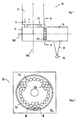
- the kinematic location 22 includes an annular array of spherical supports 124 located on a member 114 which forms part of the pivot joint 14. Located on the mating face 116 of the probe 16 are three pairs of cylinders 126 which are spaced equally around the horizontal axis 100. The spherical supports 124 and cylinders 126 are two sets of mutually engageable detent elements. The annular array of spherical supports 124 and cylinders 126 are biased into engagement by, for example, a spring (not shown). A similar arrangement can be used for the kinematic location 24.
- Figs 4a to 4d and 5a to 5d illustrate a problem which is mitigated.
- Fig 4 shows an articulating mechanism which comprises a first body 114 having an array of spherical supports 124 which engage with three pairs of cylinders 126 located on a second body 116.
- Fig 5 shows an alternative arrangement where a first body 214 includes one set of gear teeth 224 which engage with a second set of gear teeth 226 located on a second body 216. The amount of misalignment shown if Figs 4 and 5 has been exaggerated in order to more clearly illustrate the misalignment.
- a relative movement 150,250 of the first 114,214 body with respect to the second 116,216 body has occurred.
- the cylinders 126 and gear teeth 226 do not sit centrally (as shown by line 200) in the mutually convergent surfaces of the balls 124 and teeth 224 that they are engaged with.
- a relative movement 160,260 of the first 114,214 body with respect to the second 116,216 body has occurred in the opposite direction to that previously described.
- the two bodies 114,116 and 214,216 are subsequently engaged or re-constrained ( Figs 4d,5d ) locking the articulating mechanism, the cylinders 126 and gear teeth 226 again do not sit centrally (as shown by line 200) in the mutually convergent surfaces of the balls 124 and teeth 224 that they are engaged with.
- a further example of an articulating mechanism comprises a belt which includes a plurality of teeth on one of the bodies.
- a further advantage of the invention is that because the desired position is approached from the same direction the position in which the articulating mechanism is locked can be designated as the actual position.
- Fig 6 shows an alternative touch probe 250 having a probing tip 252 which is connected to a quill 254 via an elongate arm 256.
- the elongate arm 256 is attached to the quill via two rotatable members or articulating mechanisms (not shown) which enable rotary movement about axes D and E respectively.
- the elongate arm 256 will bend. To mitigate any errors that would be introduced by such bending, a consistent acceleration is used when the probe tip approaches the new position. Additionally, it is preferred that the new position is approached from the same direction each time a movement is effected.
- the touch probe is provided with a breakout connection 258.
- the breakout connection preferentially breaks before any fragile or expensive components are damaged.
- the use of such a breakout connection can be a source of error in the positioning of the probe tip, especially when high speed movement is used as such movement can cause the probe arm to bend and this is transferred back to the breakout connection. For this reason as well, consistent acceleration or constant velocity is used when moving to a new position.
- potentiometers Two ways in which the position of the articulating mechanism of Fig 6 is controlled is by a potentiometer or an encoder.
- the index position or location is indicated by the value of a voltage signal. In probe systems, this signal typically changes by 22mV per degree.
- encoders a position count is used.
- Potentiometers have a tendency to drift over time so the voltage signal which is associated with a particular index location or position will change. Also, as potentiometers do not vary linearly, a range of voltage values is given for each location. This can result in movement of the articulating mechanism to the wrong location.
- the invention provides a method of identifying this drift and a method of positioning the articulating mechanism so that rather than giving each location a range for the voltage signal, an exact value can be assigned. To enable this, for each articulating mechanism, each position must be approached in the same manner according to the first aspect of the invention i.e. under particular conditions, for example, from the same direction and preferably the same distance. This will give an absolute voltage reading for each position when locked which is recorded in a table and used either manually or electronically each time the articulating mechanism is moved to a new position.
- This table may be updated every time you lock into a position. Alternatively, on a subsequent movement under the same conditions to a position, a signal or reading is obtained, and if there is a difference between that reading and the recorded reading, the articulating mechanism is moved until that reading corresponds to the recorded reading.
- any difference between the recorded or tabular reading and the present or indicative reading may be flagged.
- the difference is flagged only when the difference between tabular reading and actual reading reaches a certain amount or value i.e. when drift of the potentiometer has reached an unacceptable amount.
- Fig 7 is a flow diagram 300 showing the steps that are carried out when an articulating mechanism is moved to a new position.
- the articulating mechanism is unlocked or released 310.
- a first target position 320 is set as the new position plus a value X and the articulating mechanism moved towards this first target position.
- the target position is changed and set as the new position 340.
- the movement to the new position occurs under particular conditions.
- the mechanism reaches the new position 350 (or second target position)
- the articulating mechanism is locked, re-constrained or engaged in that position 360.
- the value of X is selected as a nominal amount, for example 3° or 66mV depending on the technique used to establish location.
- a controller controls the movement of the articulating mechanism and one way to establish whether a target position has been reached is to use a comparator which compares the current position of the articulating mechanism with the target position. When there is no difference, the motion is stopped or paused.
- X will be of constant value regardless of whether the probe is initially moved in a clockwise or anti-clockwise direction.
- the movement of the articulating mechanism may be to move a certain number of degrees.
- the direction from which the articulating mechanism moves to the new position is set as clockwise, then when there is less than 180° of a circle to travel to reach the new position, X will have a negative value so the mechanism pauses before it reaches the new position. If there is more than 180° of the mechanism to traverse to reach the new position then either one clockwise movement can be made having X as negative or, a shorter anti-clockwise manoeuvre can be made. However, in this circumstance X is positive thus, the mechanism will move passed the new position and return to it moving in the clockwise direction.
- the controller ( Fig 1 , 11) which controls the movement may be located in the probe or in a separate controller unit.
- the invention can be carried out as part of the lock up or engagement procedure for the articulating device.
- the articulating device is moved to the new or desired position and then, during the locking process, prior to the re-engagement of the device, a relative movement between the two parts of the device to an adjacent position and back to the new position occurs.
- an initial target position is set as the new position 302 and the articulating mechanism is moved towards this initial target position.
- the target position is changed 304 and set as the first target position 320 which is the new position plus a value X. The procedure then continues as described above.
- Fig 8 shows a coordinate measuring machine (CMM) 400 including a base 402 onto which a sample may be placed and a gantry 404 which supports a measuring probe 406 and enables movement of the probe with respect to the base in x, y and z directions.
- CMM coordinate measuring machine
- the CMM 400 is provided with a rotary table 410 which sits on the base 402.
- the rotary table 410 is an articulating mechanism which has two parts 410a,410b which when disengaged (not shown) are relatively rotatable, using power from motor 414, enabling rotation of a sample 412 placed thereon with respect to the probe 406.
- the rotary table 410 is, for example, a Hirth coupling comprising interlocking gear teeth.
- a measuring device includes machines such as coordinate measuring machines, machine tools, lathes, measuring machines, manual co-ordinate measuring arms, non-Cartesian mechanisms and other parallel kinematic machines (such as tripods and hexapods), robots, for example work inspection robots, and single axis machines.
- machines such as coordinate measuring machines, machine tools, lathes, measuring machines, manual co-ordinate measuring arms, non-Cartesian mechanisms and other parallel kinematic machines (such as tripods and hexapods), robots, for example work inspection robots, and single axis machines.
Landscapes
- Engineering & Computer Science (AREA)
- Physics & Mathematics (AREA)
- General Physics & Mathematics (AREA)
- Human Computer Interaction (AREA)
- Manufacturing & Machinery (AREA)
- Automation & Control Theory (AREA)
- A Measuring Device Byusing Mechanical Method (AREA)
- Length Measuring Devices With Unspecified Measuring Means (AREA)
- Control Of Position Or Direction (AREA)
Claims (10)
- Verfahren zum Positionieren eines Gelenkmechanismus für eine Messvorrichtung, mit zwei Körpern, die relativ bewegbar und in jeder einer Mehrzahl definierter Indexpositionen verriegelbar sind; zwei Sätzen von Sperrelementen, wobei sich ein Satz an jedem Körper befindet; wobei die Sperrelemente gegenseitig in Eingriff treten, um die Körper in den definierten Positionen zu verriegeln, und aus dem Eingriff freigegeben werden, wenn die Körper entriegelt werden; wobei eine Ablesung vorgesehen ist, die die relative Position der beiden Körper angibt, wobei das Verfahren gekennzeichnet ist durch:(a) Entriegeln der beiden Körper durch Freigeben der Sperrelemente aus dem Eingriff;(b) Vergleichen der gegenwärtigen Ablesung, die die Position angibt, mit einer aufgezeichneten Ablesung;
wobei die aufgezeichnete Ablesung aufgezeichnet wurde, als die beiden Körper der Gelenkvorrichtung so verriegelt waren, dass die Sperrelemente in Eingriff standen;(c) Bewegen der beiden Körper, bis die gegenwärtige Ablesung der aufgezeichneten Ablesung entspricht; und(d) Verriegeln der beiden Körper durch Eingriff der Sperrelemente. - Verfahren nach Anspruch 1,
mit einem Schritt zum Aufzeichnen der Ablesungen, wenn die Körper in der Mehrzahl definierter Positionen verriegelt werden. - Verfahren nach einem der Ansprüche 1 oder 2,
wobei die aufgezeichneten Ablesungen für die Mehrzahl definierter Positionen in einer Tabelle aufgezeichnet werden. - Verfahren nach Anspruch 3,
wobei die Tabelle jedes Mal aktualisiert wird, wenn die Körper in eine definierte Position verriegelt werden. - Verfahren nach Anspruch 3,
wobei die Ablesung, die die relative Position der beiden Körper angibt, durch ein Potentiometer oder einen Codierer bereitgestellt wird, und wobei jegliche Differenz zwischen der aufgezeichneten oder tabellarischen Ablesung und der gegenwärtigen Ablesung markiert wird, wenn die Differenz einen gewissen Betrag oder Wert erreicht, der einer Drift des Potentiometers oder dem, wenn der Codierer einen nicht akzeptablen Betrag erreicht, entspricht. - Gelenkvorrichtung für eine Messvorrichtung, umfassend:einen Gelenkmechanismus, der zwei relativ bewegbare Körper umfasst, die in eine Mehrzahl definierter Indexpositionen verriegel- und entriegelbar sind, wobei zwei Sätze von Sperrelementen vorgesehen sind, wobei sich ein Satz an jedem Körper befindet;wobei die Sperrelemente gegenseitig in Eingriff stehen, um die Körper in den definierten Positionen zu verriegeln, und freigegeben sind, wenn die Körper entriegelt sind; gekennzeichnet durch aufgezeichnete Ablesungen, die die relative Position der beiden Körper angeben, wenn die Körper in jeder der Mehrzahl definierter Positionen verriegelt sind, wobei die Sperrelemente in Eingriff stehen;einen Controller, der derart angeordnet ist, eine gegenwärtige Positionsablesung für die beiden relativ bewegbaren Körper mit einer aufgezeichneten Ablesung zu vergleichen und eine Bewegung der beiden relativ bewegbaren Körper zu steuern, wenn die Sperrelemente freigegeben sind, wobei die Bewegung der Körper gestoppt wird, wenn keine Differenz zwischen der gegenwärtigen und aufgezeichneten Position vorhanden ist, und die Körper dann durch Eingriff der Sperrelemente verriegelt werden.
- Gelenkvorrichtung nach Anspruch 6,
wobei die Ablesungen, die die relative Position der beiden Körper angeben, wenn die Körper verriegelt sind, in einer Tabelle aufgezeichnet werden. - Gelenkvorrichtung nach Anspruch 7,
die derart angeordnet ist, die Tabelle jedes Mal zu aktualisieren, wenn die Körper in eine definierte Position verriegelt sind. - Gelenkvorrichtung nach Anspruch 7,
die ein Potentiometer oder einen Codierer aufweist, der die Ablesung bereitstellt, die die relative Position der beiden Körper angibt, und derart angeordnet ist, jegliche Differenz zwischen der aufgezeichneten oder tabellarischen Ablesung und der gegenwärtigen Ablesung zu markieren, wenn die Differenz einen gewissen Betrag oder Wert erreicht, der einer Drift des Potentiometers oder dem, wenn der Codierer einen nicht akzeptablen Betrag erreicht, entspricht. - Messmaschine mit einer Gelenkvorrichtung nach einem der Ansprüche 6 bis 9.
Applications Claiming Priority (2)
| Application Number | Priority Date | Filing Date | Title |
|---|---|---|---|
| GBGB0501690.2A GB0501690D0 (en) | 2005-01-27 | 2005-01-27 | Articulating device |
| EP06703199A EP1844371B1 (de) | 2005-01-27 | 2006-01-25 | Gelenkvorrichtung |
Related Parent Applications (1)
| Application Number | Title | Priority Date | Filing Date |
|---|---|---|---|
| EP06703199.7 Division | 2006-01-25 |
Publications (3)
| Publication Number | Publication Date |
|---|---|
| EP2221691A2 EP2221691A2 (de) | 2010-08-25 |
| EP2221691A3 EP2221691A3 (de) | 2011-04-06 |
| EP2221691B1 true EP2221691B1 (de) | 2013-09-18 |
Family
ID=34259754
Family Applications (2)
| Application Number | Title | Priority Date | Filing Date |
|---|---|---|---|
| EP10004149.0A Expired - Lifetime EP2221691B1 (de) | 2005-01-27 | 2006-01-25 | Eine gelenkbildende Vorrichtung |
| EP06703199A Expired - Lifetime EP1844371B1 (de) | 2005-01-27 | 2006-01-25 | Gelenkvorrichtung |
Family Applications After (1)
| Application Number | Title | Priority Date | Filing Date |
|---|---|---|---|
| EP06703199A Expired - Lifetime EP1844371B1 (de) | 2005-01-27 | 2006-01-25 | Gelenkvorrichtung |
Country Status (6)
| Country | Link |
|---|---|
| US (2) | US7350310B2 (de) |
| EP (2) | EP2221691B1 (de) |
| JP (2) | JP5341355B2 (de) |
| CN (1) | CN101107580B (de) |
| GB (1) | GB0501690D0 (de) |
| WO (1) | WO2006079794A1 (de) |
Families Citing this family (16)
| Publication number | Priority date | Publication date | Assignee | Title |
|---|---|---|---|---|
| EP1666832B1 (de) * | 2004-12-01 | 2012-08-29 | Tesa Sa | Motorisierter orientierbarer Messkopf |
| EP1672309B1 (de) * | 2004-12-01 | 2008-02-13 | Tesa SA | Motorisierter und orientierbarer Messkopf |
| EP1666833B1 (de) * | 2004-12-01 | 2008-01-23 | Tesa SA | Motorisierter und orientierbarer Messkopf |
| GB0501690D0 (en) * | 2005-01-27 | 2005-03-02 | Renishaw Plc | Articulating device |
| GB0707720D0 (en) * | 2007-04-23 | 2007-05-30 | Renishaw Plc | Apparatus and method for controlling or programming a measurement routine |
| GB0716218D0 (en) | 2007-08-20 | 2007-09-26 | Renishaw Plc | Measurement path generation |
| US9377284B2 (en) | 2010-04-30 | 2016-06-28 | Renishaw Plc | Metrology apparatus |
| DE202013012759U1 (de) * | 2013-01-30 | 2019-04-23 | Jenoptik Industrial Metrology Germany Gmbh | Tastkörper-Halteanordnung |
| EP2889573B1 (de) | 2013-12-24 | 2016-06-15 | Tesa Sa | Orientbarer motorisierter Messkopf |
| US9840968B2 (en) | 2015-09-16 | 2017-12-12 | Hamilton Sundstrand Corporation | Topologies and methods for turbine engine start inverters |
| JP6470854B2 (ja) * | 2018-01-10 | 2019-02-13 | 株式会社東京精密 | 3次元測定機 |
| WO2022175656A1 (en) | 2021-02-17 | 2022-08-25 | Renishaw Plc | Articulated head |
| GB202102201D0 (en) | 2021-02-17 | 2021-03-31 | Renishaw Plc | Metrology apparatus |
| GB202102199D0 (en) | 2021-02-17 | 2021-03-31 | Renishaw Plc | Articulated joint |
| GB202102200D0 (en) | 2021-02-17 | 2021-03-31 | Renishaw Plc | Articulated member |
| EP4321834A1 (de) | 2022-08-10 | 2024-02-14 | Renishaw PLC | Indiziertes gelenk mit einem sensor zur festlegung eines eingriffszustands und zugehörige metrologievorrichtung |
Family Cites Families (42)
| Publication number | Priority date | Publication date | Assignee | Title |
|---|---|---|---|---|
| FR1222480A (fr) | 1958-10-22 | 1960-06-10 | Renault | Mode opérationnel de mise en position automatique d'un organe mécanique |
| US3552026A (en) * | 1969-04-17 | 1971-01-05 | Leo N Fedoroff | Precise angle measuring device |
| US3636635A (en) * | 1969-10-07 | 1972-01-25 | Jerome H Lemelson | Automatic measurement apparatus |
| US3750295A (en) * | 1971-07-22 | 1973-08-07 | Werkzeugmasch Veb | Measuring machine |
| US3844461A (en) * | 1973-04-09 | 1974-10-29 | Gerber Scientific Instr Co | Precise indexing apparatus and method |
| GB1597842A (en) | 1977-02-07 | 1981-09-09 | Rolls Royce | Indexing mechanism |
| DE3301205C2 (de) * | 1982-02-26 | 1985-10-03 | Dr. Johannes Heidenhain Gmbh, 8225 Traunreut | Winkelmeßeinrichtung |
| JP2585992B2 (ja) * | 1987-05-19 | 1997-02-26 | 株式会社ニコン | 電動プロ−ブのプロ−ブ角度制御装置 |
| DE3740070A1 (de) * | 1987-11-26 | 1989-06-08 | Zeiss Carl Fa | Dreh-schwenk-einrichtung fuer tastkoepfe von koordinatenmessgeraeten |
| US5189806A (en) * | 1988-12-19 | 1993-03-02 | Renishaw Plc | Method of and apparatus for scanning the surface of a workpiece |
| GB8906287D0 (en) * | 1989-03-18 | 1989-05-04 | Renishaw Plc | Probe calibration |
| JPH0310742A (ja) * | 1989-06-07 | 1991-01-18 | Fanuc Ltd | 絶対位置決め方式 |
| US5222034A (en) * | 1990-10-10 | 1993-06-22 | Shelton Russell S | Measuring method and apparatus |
| CA2115037A1 (en) | 1991-08-06 | 1993-02-18 | Roger Sydney Benest | Method and apparatus for crop spraying |
| US5374883A (en) * | 1992-09-02 | 1994-12-20 | Cincinnati Milacron Inc. | Method and apparatus for position error compensation |
| DE4232950A1 (de) * | 1992-10-01 | 1994-04-07 | Bosch Gmbh Robert | Vorrichtung zur Lageregelung eines bewegbaren Teils |
| US5412880A (en) * | 1993-02-23 | 1995-05-09 | Faro Technologies Inc. | Method of constructing a 3-dimensional map of a measurable quantity using three dimensional coordinate measuring apparatus |
| JPH0727557A (ja) * | 1993-07-08 | 1995-01-27 | Mitsutoyo Corp | 三次元測定機 |
| DE19681395T1 (de) * | 1995-05-16 | 1998-04-16 | Brown & Sharpe Mfg | Koordinatenmeßmaschine mit Gelenkarm |
| KR100271854B1 (ko) * | 1996-11-29 | 2000-11-15 | 선우중호 | 다축기계의 3차원입체오차측정방법 |
| DE69814198T2 (de) * | 1997-02-10 | 2004-04-08 | Mitutoyo Corp., Kawasaki | Messverfahren und Messinstrument mit Triggersonde |
| DE10006753A1 (de) * | 2000-02-15 | 2001-08-16 | Zeiss Carl | Dreh-Schwenkeinrichtung für den Tastkopf eines Koordinatenmeßgerätes |
| JP2001264050A (ja) * | 2000-03-14 | 2001-09-26 | Mitsutoyo Corp | 微細形状測定装置 |
| US6668466B1 (en) * | 2000-10-19 | 2003-12-30 | Sandia Corporation | Highly accurate articulated coordinate measuring machine |
| GB0114360D0 (en) * | 2001-06-13 | 2001-08-08 | Renishaw Plc | Stylus orientation |
| CN1430118A (zh) * | 2001-12-31 | 2003-07-16 | 中山市科力高自动化设备有限公司 | 自动化设备定位控制机构 |
| GB0207912D0 (en) * | 2002-04-05 | 2002-05-15 | Renishaw Plc | Kinematic coupling |
| AU2003227595A1 (en) | 2002-04-19 | 2003-11-03 | Ciba Specialty Chemicals Holding Inc. | Foam control agents |
| GB0215152D0 (en) * | 2002-07-01 | 2002-08-07 | Renishaw Plc | Probe or stylus orientation |
| EP1443301B1 (de) * | 2003-01-29 | 2010-02-10 | Tesa SA | Lenkbarer Taststift |
| US6817108B2 (en) * | 2003-02-05 | 2004-11-16 | Homer L. Eaton | Articulation measuring arm having rotatable part-carrying platen |
| US6772527B1 (en) * | 2003-04-09 | 2004-08-10 | Renishaw Plc | Modular measurement device |
| US7152456B2 (en) * | 2004-01-14 | 2006-12-26 | Romer Incorporated | Automated robotic measuring system |
| US7693325B2 (en) * | 2004-01-14 | 2010-04-06 | Hexagon Metrology, Inc. | Transprojection of geometry data |
| EP1672309B1 (de) * | 2004-12-01 | 2008-02-13 | Tesa SA | Motorisierter und orientierbarer Messkopf |
| GB0501690D0 (en) * | 2005-01-27 | 2005-03-02 | Renishaw Plc | Articulating device |
| FR2884910B1 (fr) * | 2005-04-20 | 2007-07-13 | Romer Sa | Appareil de mesure tridimensionnelle a bras articules comportant une pluralite d'axes d'articulation |
| JP2008547026A (ja) * | 2005-06-23 | 2008-12-25 | ファロ テクノロジーズ インコーポレーテッド | 有関節座標計測機再配置装置及び方法 |
| GB0603128D0 (en) * | 2006-02-16 | 2006-03-29 | Renishaw Plc | Articulating probe head apparatus |
| EP2064514B2 (de) * | 2006-09-05 | 2014-08-06 | Renishaw PLC | Oberflächenmessgerät |
| EP2108917B1 (de) * | 2008-04-07 | 2012-10-03 | Leica Geosystems AG | Koordinatenmessgerät mit Gelenkarm |
| US7908757B2 (en) * | 2008-10-16 | 2011-03-22 | Hexagon Metrology, Inc. | Articulating measuring arm with laser scanner |
-
2005
- 2005-01-27 GB GBGB0501690.2A patent/GB0501690D0/en not_active Ceased
-
2006
- 2006-01-25 JP JP2007552709A patent/JP5341355B2/ja not_active Expired - Lifetime
- 2006-01-25 CN CN2006800027830A patent/CN101107580B/zh not_active Expired - Lifetime
- 2006-01-25 EP EP10004149.0A patent/EP2221691B1/de not_active Expired - Lifetime
- 2006-01-25 EP EP06703199A patent/EP1844371B1/de not_active Expired - Lifetime
- 2006-01-25 WO PCT/GB2006/000235 patent/WO2006079794A1/en not_active Ceased
- 2006-01-27 US US11/340,609 patent/US7350310B2/en not_active Ceased
-
2010
- 2010-03-31 US US12/662,143 patent/USRE43250E1/en not_active Expired - Lifetime
-
2013
- 2013-04-08 JP JP2013080647A patent/JP6085513B2/ja not_active Expired - Fee Related
Also Published As
| Publication number | Publication date |
|---|---|
| US7350310B2 (en) | 2008-04-01 |
| JP6085513B2 (ja) | 2017-02-22 |
| JP2008534916A (ja) | 2008-08-28 |
| GB0501690D0 (en) | 2005-03-02 |
| JP2013210371A (ja) | 2013-10-10 |
| EP2221691A3 (de) | 2011-04-06 |
| EP2221691A2 (de) | 2010-08-25 |
| JP5341355B2 (ja) | 2013-11-13 |
| EP1844371A1 (de) | 2007-10-17 |
| WO2006079794A1 (en) | 2006-08-03 |
| EP1844371B1 (de) | 2013-03-20 |
| US20060196066A1 (en) | 2006-09-07 |
| USRE43250E1 (en) | 2012-03-20 |
| CN101107580B (zh) | 2010-11-10 |
| CN101107580A (zh) | 2008-01-16 |
Similar Documents
| Publication | Publication Date | Title |
|---|---|---|
| USRE43250E1 (en) | Articulating device | |
| DE102017206571B4 (de) | Fehleridentifikationsverfahren einer Werkzeugmaschine und Fehleridentifikationssystem derselben | |
| JP6235336B2 (ja) | 座標位置決め装置を再較正するための方法 | |
| EP1988357B1 (de) | Verfahren und Vorrichtung zur Koordinatenmessung | |
| EP3402628B1 (de) | Kalibrierverfahren | |
| CN102483621B (zh) | 机床校准方法 | |
| US8479403B2 (en) | Measuring system | |
| JP6586112B2 (ja) | 工作機械の誤差同定方法及び誤差同定システム | |
| JP7682199B2 (ja) | 較正デバイスおよび方法 | |
| US5767380A (en) | Measuring arrangement and method for checking the geometric and dynamic accuracy of two machine elements displaceable with respect to one another | |
| JP7410189B2 (ja) | ロボットのキャリブレーション装置 | |
| EP4524506A1 (de) | Gelenkiger sondenkopf | |
| EP4653802A1 (de) | Indiziertes gelenk | |
| JP2021049591A (ja) | 工作機械における機上測定方法 | |
| WO2021220142A1 (en) | Devices and method for calibrating industrial robots | |
| HK1123091A (en) | Coordinate measuring method and device | |
| HK1124110B (en) | Multi-axis positioning and measuring system and method of using | |
| HK1124110A1 (en) | Multi-axis positioning and measuring system and method of using |
Legal Events
| Date | Code | Title | Description |
|---|---|---|---|
| PUAI | Public reference made under article 153(3) epc to a published international application that has entered the european phase |
Free format text: ORIGINAL CODE: 0009012 |
|
| 17P | Request for examination filed |
Effective date: 20100419 |
|
| AC | Divisional application: reference to earlier application |
Ref document number: 1844371 Country of ref document: EP Kind code of ref document: P |
|
| AK | Designated contracting states |
Kind code of ref document: A2 Designated state(s): AT BE BG CH CY CZ DE DK EE ES FI FR GB GR HU IE IS IT LI LT LU LV MC NL PL PT RO SE SI SK TR |
|
| AX | Request for extension of the european patent |
Extension state: BA HR MK YU |
|
| PUAL | Search report despatched |
Free format text: ORIGINAL CODE: 0009013 |
|
| AK | Designated contracting states |
Kind code of ref document: A3 Designated state(s): AT BE BG CH CY CZ DE DK EE ES FI FR GB GR HU IE IS IT LI LT LU LV MC NL PL PT RO SE SI SK TR |
|
| AX | Request for extension of the european patent |
Extension state: BA HR MK YU |
|
| 17Q | First examination report despatched |
Effective date: 20120305 |
|
| GRAP | Despatch of communication of intention to grant a patent |
Free format text: ORIGINAL CODE: EPIDOSNIGR1 |
|
| GRAS | Grant fee paid |
Free format text: ORIGINAL CODE: EPIDOSNIGR3 |
|
| GRAP | Despatch of communication of intention to grant a patent |
Free format text: ORIGINAL CODE: EPIDOSNIGR1 |
|
| GRAA | (expected) grant |
Free format text: ORIGINAL CODE: 0009210 |
|
| INTG | Intention to grant announced |
Effective date: 20130729 |
|
| AC | Divisional application: reference to earlier application |
Ref document number: 1844371 Country of ref document: EP Kind code of ref document: P |
|
| AK | Designated contracting states |
Kind code of ref document: B1 Designated state(s): AT BE BG CH CY CZ DE DK EE ES FI FR GB GR HU IE IS IT LI LT LU LV MC NL PL PT RO SE SI SK TR |
|
| REG | Reference to a national code |
Ref country code: GB Ref legal event code: FG4D |
|
| REG | Reference to a national code |
Ref country code: CH Ref legal event code: NV Representative=s name: KIRKER AND CIE S.A., CH Ref country code: CH Ref legal event code: EP |
|
| REG | Reference to a national code |
Ref country code: IE Ref legal event code: FG4D |
|
| REG | Reference to a national code |
Ref country code: AT Ref legal event code: REF Ref document number: 633089 Country of ref document: AT Kind code of ref document: T Effective date: 20131015 |
|
| REG | Reference to a national code |
Ref country code: DE Ref legal event code: R096 Ref document number: 602006038528 Country of ref document: DE Effective date: 20131114 |
|
| PG25 | Lapsed in a contracting state [announced via postgrant information from national office to epo] |
Ref country code: LT Free format text: LAPSE BECAUSE OF FAILURE TO SUBMIT A TRANSLATION OF THE DESCRIPTION OR TO PAY THE FEE WITHIN THE PRESCRIBED TIME-LIMIT Effective date: 20130918 Ref country code: CY Free format text: LAPSE BECAUSE OF FAILURE TO SUBMIT A TRANSLATION OF THE DESCRIPTION OR TO PAY THE FEE WITHIN THE PRESCRIBED TIME-LIMIT Effective date: 20130904 Ref country code: SE Free format text: LAPSE BECAUSE OF FAILURE TO SUBMIT A TRANSLATION OF THE DESCRIPTION OR TO PAY THE FEE WITHIN THE PRESCRIBED TIME-LIMIT Effective date: 20130918 |
|
| REG | Reference to a national code |
Ref country code: NL Ref legal event code: VDEP Effective date: 20130918 |
|
| REG | Reference to a national code |
Ref country code: AT Ref legal event code: MK05 Ref document number: 633089 Country of ref document: AT Kind code of ref document: T Effective date: 20130918 |
|
| REG | Reference to a national code |
Ref country code: LT Ref legal event code: MG4D |
|
| PG25 | Lapsed in a contracting state [announced via postgrant information from national office to epo] |
Ref country code: LV Free format text: LAPSE BECAUSE OF FAILURE TO SUBMIT A TRANSLATION OF THE DESCRIPTION OR TO PAY THE FEE WITHIN THE PRESCRIBED TIME-LIMIT Effective date: 20130918 Ref country code: GR Free format text: LAPSE BECAUSE OF FAILURE TO SUBMIT A TRANSLATION OF THE DESCRIPTION OR TO PAY THE FEE WITHIN THE PRESCRIBED TIME-LIMIT Effective date: 20131219 Ref country code: SI Free format text: LAPSE BECAUSE OF FAILURE TO SUBMIT A TRANSLATION OF THE DESCRIPTION OR TO PAY THE FEE WITHIN THE PRESCRIBED TIME-LIMIT Effective date: 20130918 Ref country code: FI Free format text: LAPSE BECAUSE OF FAILURE TO SUBMIT A TRANSLATION OF THE DESCRIPTION OR TO PAY THE FEE WITHIN THE PRESCRIBED TIME-LIMIT Effective date: 20130918 |
|
| PG25 | Lapsed in a contracting state [announced via postgrant information from national office to epo] |
Ref country code: BE Free format text: LAPSE BECAUSE OF FAILURE TO SUBMIT A TRANSLATION OF THE DESCRIPTION OR TO PAY THE FEE WITHIN THE PRESCRIBED TIME-LIMIT Effective date: 20130918 Ref country code: CY Free format text: LAPSE BECAUSE OF FAILURE TO SUBMIT A TRANSLATION OF THE DESCRIPTION OR TO PAY THE FEE WITHIN THE PRESCRIBED TIME-LIMIT Effective date: 20130918 |
|
| PG25 | Lapsed in a contracting state [announced via postgrant information from national office to epo] |
Ref country code: SK Free format text: LAPSE BECAUSE OF FAILURE TO SUBMIT A TRANSLATION OF THE DESCRIPTION OR TO PAY THE FEE WITHIN THE PRESCRIBED TIME-LIMIT Effective date: 20130918 Ref country code: CZ Free format text: LAPSE BECAUSE OF FAILURE TO SUBMIT A TRANSLATION OF THE DESCRIPTION OR TO PAY THE FEE WITHIN THE PRESCRIBED TIME-LIMIT Effective date: 20130918 Ref country code: NL Free format text: LAPSE BECAUSE OF FAILURE TO SUBMIT A TRANSLATION OF THE DESCRIPTION OR TO PAY THE FEE WITHIN THE PRESCRIBED TIME-LIMIT Effective date: 20130918 Ref country code: IS Free format text: LAPSE BECAUSE OF FAILURE TO SUBMIT A TRANSLATION OF THE DESCRIPTION OR TO PAY THE FEE WITHIN THE PRESCRIBED TIME-LIMIT Effective date: 20140118 Ref country code: EE Free format text: LAPSE BECAUSE OF FAILURE TO SUBMIT A TRANSLATION OF THE DESCRIPTION OR TO PAY THE FEE WITHIN THE PRESCRIBED TIME-LIMIT Effective date: 20130918 |
|
| PG25 | Lapsed in a contracting state [announced via postgrant information from national office to epo] |
Ref country code: ES Free format text: LAPSE BECAUSE OF FAILURE TO SUBMIT A TRANSLATION OF THE DESCRIPTION OR TO PAY THE FEE WITHIN THE PRESCRIBED TIME-LIMIT Effective date: 20130918 Ref country code: PL Free format text: LAPSE BECAUSE OF FAILURE TO SUBMIT A TRANSLATION OF THE DESCRIPTION OR TO PAY THE FEE WITHIN THE PRESCRIBED TIME-LIMIT Effective date: 20130918 Ref country code: AT Free format text: LAPSE BECAUSE OF FAILURE TO SUBMIT A TRANSLATION OF THE DESCRIPTION OR TO PAY THE FEE WITHIN THE PRESCRIBED TIME-LIMIT Effective date: 20130918 |
|
| REG | Reference to a national code |
Ref country code: DE Ref legal event code: R097 Ref document number: 602006038528 Country of ref document: DE |
|
| PG25 | Lapsed in a contracting state [announced via postgrant information from national office to epo] |
Ref country code: PT Free format text: LAPSE BECAUSE OF FAILURE TO SUBMIT A TRANSLATION OF THE DESCRIPTION OR TO PAY THE FEE WITHIN THE PRESCRIBED TIME-LIMIT Effective date: 20140120 |
|
| PLBE | No opposition filed within time limit |
Free format text: ORIGINAL CODE: 0009261 |
|
| STAA | Information on the status of an ep patent application or granted ep patent |
Free format text: STATUS: NO OPPOSITION FILED WITHIN TIME LIMIT |
|
| 26N | No opposition filed |
Effective date: 20140619 |
|
| PG25 | Lapsed in a contracting state [announced via postgrant information from national office to epo] |
Ref country code: MC Free format text: LAPSE BECAUSE OF FAILURE TO SUBMIT A TRANSLATION OF THE DESCRIPTION OR TO PAY THE FEE WITHIN THE PRESCRIBED TIME-LIMIT Effective date: 20130918 Ref country code: LU Free format text: LAPSE BECAUSE OF FAILURE TO SUBMIT A TRANSLATION OF THE DESCRIPTION OR TO PAY THE FEE WITHIN THE PRESCRIBED TIME-LIMIT Effective date: 20140125 |
|
| PG25 | Lapsed in a contracting state [announced via postgrant information from national office to epo] |
Ref country code: DK Free format text: LAPSE BECAUSE OF FAILURE TO SUBMIT A TRANSLATION OF THE DESCRIPTION OR TO PAY THE FEE WITHIN THE PRESCRIBED TIME-LIMIT Effective date: 20130918 |
|
| REG | Reference to a national code |
Ref country code: DE Ref legal event code: R097 Ref document number: 602006038528 Country of ref document: DE Effective date: 20140619 |
|
| REG | Reference to a national code |
Ref country code: FR Ref legal event code: ST Effective date: 20140930 |
|
| REG | Reference to a national code |
Ref country code: IE Ref legal event code: MM4A |
|
| PG25 | Lapsed in a contracting state [announced via postgrant information from national office to epo] |
Ref country code: FR Free format text: LAPSE BECAUSE OF NON-PAYMENT OF DUE FEES Effective date: 20140131 |
|
| PG25 | Lapsed in a contracting state [announced via postgrant information from national office to epo] |
Ref country code: IE Free format text: LAPSE BECAUSE OF NON-PAYMENT OF DUE FEES Effective date: 20140125 |
|
| PG25 | Lapsed in a contracting state [announced via postgrant information from national office to epo] |
Ref country code: BG Free format text: LAPSE BECAUSE OF FAILURE TO SUBMIT A TRANSLATION OF THE DESCRIPTION OR TO PAY THE FEE WITHIN THE PRESCRIBED TIME-LIMIT Effective date: 20130918 Ref country code: RO Free format text: LAPSE BECAUSE OF FAILURE TO SUBMIT A TRANSLATION OF THE DESCRIPTION OR TO PAY THE FEE WITHIN THE PRESCRIBED TIME-LIMIT Effective date: 20130918 |
|
| PG25 | Lapsed in a contracting state [announced via postgrant information from national office to epo] |
Ref country code: HU Free format text: LAPSE BECAUSE OF FAILURE TO SUBMIT A TRANSLATION OF THE DESCRIPTION OR TO PAY THE FEE WITHIN THE PRESCRIBED TIME-LIMIT; INVALID AB INITIO Effective date: 20060125 Ref country code: TR Free format text: LAPSE BECAUSE OF FAILURE TO SUBMIT A TRANSLATION OF THE DESCRIPTION OR TO PAY THE FEE WITHIN THE PRESCRIBED TIME-LIMIT Effective date: 20130918 |
|
| PGFP | Annual fee paid to national office [announced via postgrant information from national office to epo] |
Ref country code: IT Payment date: 20200123 Year of fee payment: 15 |
|
| PG25 | Lapsed in a contracting state [announced via postgrant information from national office to epo] |
Ref country code: IT Free format text: LAPSE BECAUSE OF NON-PAYMENT OF DUE FEES Effective date: 20210125 |
|
| PGFP | Annual fee paid to national office [announced via postgrant information from national office to epo] |
Ref country code: DE Payment date: 20230127 Year of fee payment: 18 |
|
| P01 | Opt-out of the competence of the unified patent court (upc) registered |
Effective date: 20230602 |
|
| REG | Reference to a national code |
Ref country code: DE Ref legal event code: R119 Ref document number: 602006038528 Country of ref document: DE |
|
| PG25 | Lapsed in a contracting state [announced via postgrant information from national office to epo] |
Ref country code: DE Free format text: LAPSE BECAUSE OF NON-PAYMENT OF DUE FEES Effective date: 20240801 |
|
| PG25 | Lapsed in a contracting state [announced via postgrant information from national office to epo] |
Ref country code: DE Free format text: LAPSE BECAUSE OF NON-PAYMENT OF DUE FEES Effective date: 20240801 |
|
| PGFP | Annual fee paid to national office [announced via postgrant information from national office to epo] |
Ref country code: CH Payment date: 20250201 Year of fee payment: 20 |
|
| PGFP | Annual fee paid to national office [announced via postgrant information from national office to epo] |
Ref country code: GB Payment date: 20250121 Year of fee payment: 20 |
|
| REG | Reference to a national code |
Ref country code: CH Ref legal event code: H14 Free format text: ST27 STATUS EVENT CODE: U-0-0-H10-H14 (AS PROVIDED BY THE NATIONAL OFFICE) Effective date: 20260125 |
|
| REG | Reference to a national code |
Ref country code: GB Ref legal event code: PE20 Expiry date: 20260124 |