EP2220977A2 - Flaschenstöpsel - Google Patents
Flaschenstöpsel Download PDFInfo
- Publication number
- EP2220977A2 EP2220977A2 EP09154230A EP09154230A EP2220977A2 EP 2220977 A2 EP2220977 A2 EP 2220977A2 EP 09154230 A EP09154230 A EP 09154230A EP 09154230 A EP09154230 A EP 09154230A EP 2220977 A2 EP2220977 A2 EP 2220977A2
- Authority
- EP
- European Patent Office
- Prior art keywords
- stopper
- inlet
- container
- plug
- aperture
- Prior art date
- Legal status (The legal status is an assumption and is not a legal conclusion. Google has not performed a legal analysis and makes no representation as to the accuracy of the status listed.)
- Withdrawn
Links
Images




Classifications
-
- B—PERFORMING OPERATIONS; TRANSPORTING
- B65—CONVEYING; PACKING; STORING; HANDLING THIN OR FILAMENTARY MATERIAL
- B65D—CONTAINERS FOR STORAGE OR TRANSPORT OF ARTICLES OR MATERIALS, e.g. BAGS, BARRELS, BOTTLES, BOXES, CANS, CARTONS, CRATES, DRUMS, JARS, TANKS, HOPPERS, FORWARDING CONTAINERS; ACCESSORIES, CLOSURES, OR FITTINGS THEREFOR; PACKAGING ELEMENTS; PACKAGES
- B65D47/00—Closures with filling and discharging, or with discharging, devices
- B65D47/04—Closures with discharging devices other than pumps
- B65D47/20—Closures with discharging devices other than pumps comprising hand-operated members for controlling discharge
- B65D47/26—Closures with discharging devices other than pumps comprising hand-operated members for controlling discharge with slide valves, i.e. valves that open and close a passageway by sliding over a port, e.g. formed with slidable spouts
- B65D47/28—Closures with discharging devices other than pumps comprising hand-operated members for controlling discharge with slide valves, i.e. valves that open and close a passageway by sliding over a port, e.g. formed with slidable spouts having linear movement
-
- A—HUMAN NECESSITIES
- A47—FURNITURE; DOMESTIC ARTICLES OR APPLIANCES; COFFEE MILLS; SPICE MILLS; SUCTION CLEANERS IN GENERAL
- A47J—KITCHEN EQUIPMENT; COFFEE MILLS; SPICE MILLS; APPARATUS FOR MAKING BEVERAGES
- A47J41/00—Thermally-insulated vessels, e.g. flasks, jugs, jars
- A47J41/0005—Thermally-insulated vessels, e.g. flasks, jugs, jars comprising a single opening for filling and dispensing provided with a stopper
- A47J41/0027—Thermally-insulated vessels, e.g. flasks, jugs, jars comprising a single opening for filling and dispensing provided with a stopper the stopper incorporating a dispensing device, i.e. the fluid being dispensed through the stopper
-
- B—PERFORMING OPERATIONS; TRANSPORTING
- B65—CONVEYING; PACKING; STORING; HANDLING THIN OR FILAMENTARY MATERIAL
- B65D—CONTAINERS FOR STORAGE OR TRANSPORT OF ARTICLES OR MATERIALS, e.g. BAGS, BARRELS, BOTTLES, BOXES, CANS, CARTONS, CRATES, DRUMS, JARS, TANKS, HOPPERS, FORWARDING CONTAINERS; ACCESSORIES, CLOSURES, OR FITTINGS THEREFOR; PACKAGING ELEMENTS; PACKAGES
- B65D47/00—Closures with filling and discharging, or with discharging, devices
- B65D47/04—Closures with discharging devices other than pumps
- B65D47/06—Closures with discharging devices other than pumps with pouring spouts or tubes; with discharge nozzles or passages
- B65D47/08—Closures with discharging devices other than pumps with pouring spouts or tubes; with discharge nozzles or passages having articulated or hinged closures
- B65D47/0857—Closures with discharging devices other than pumps with pouring spouts or tubes; with discharge nozzles or passages having articulated or hinged closures made separately from the base element provided with the spout or discharge passage
- B65D47/0866—Closures with discharging devices other than pumps with pouring spouts or tubes; with discharge nozzles or passages having articulated or hinged closures made separately from the base element provided with the spout or discharge passage and elastically biased towards the closed position only
-
- B—PERFORMING OPERATIONS; TRANSPORTING
- B65—CONVEYING; PACKING; STORING; HANDLING THIN OR FILAMENTARY MATERIAL
- B65D—CONTAINERS FOR STORAGE OR TRANSPORT OF ARTICLES OR MATERIALS, e.g. BAGS, BARRELS, BOTTLES, BOXES, CANS, CARTONS, CRATES, DRUMS, JARS, TANKS, HOPPERS, FORWARDING CONTAINERS; ACCESSORIES, CLOSURES, OR FITTINGS THEREFOR; PACKAGING ELEMENTS; PACKAGES
- B65D47/00—Closures with filling and discharging, or with discharging, devices
- B65D47/04—Closures with discharging devices other than pumps
- B65D47/20—Closures with discharging devices other than pumps comprising hand-operated members for controlling discharge
-
- B—PERFORMING OPERATIONS; TRANSPORTING
- B65—CONVEYING; PACKING; STORING; HANDLING THIN OR FILAMENTARY MATERIAL
- B65D—CONTAINERS FOR STORAGE OR TRANSPORT OF ARTICLES OR MATERIALS, e.g. BAGS, BARRELS, BOTTLES, BOXES, CANS, CARTONS, CRATES, DRUMS, JARS, TANKS, HOPPERS, FORWARDING CONTAINERS; ACCESSORIES, CLOSURES, OR FITTINGS THEREFOR; PACKAGING ELEMENTS; PACKAGES
- B65D47/00—Closures with filling and discharging, or with discharging, devices
- B65D47/04—Closures with discharging devices other than pumps
- B65D47/20—Closures with discharging devices other than pumps comprising hand-operated members for controlling discharge
- B65D47/24—Closures with discharging devices other than pumps comprising hand-operated members for controlling discharge with poppet valves or lift valves, i.e. valves opening or closing a passageway by a relative motion substantially perpendicular to the plane of the seat
- B65D47/248—Closures with discharging devices other than pumps comprising hand-operated members for controlling discharge with poppet valves or lift valves, i.e. valves opening or closing a passageway by a relative motion substantially perpendicular to the plane of the seat the valve being opened or closed by imparting a motion to the valve stem
- B65D47/249—Closures with discharging devices other than pumps comprising hand-operated members for controlling discharge with poppet valves or lift valves, i.e. valves opening or closing a passageway by a relative motion substantially perpendicular to the plane of the seat the valve being opened or closed by imparting a motion to the valve stem by means of a lever mechanism
-
- B—PERFORMING OPERATIONS; TRANSPORTING
- B65—CONVEYING; PACKING; STORING; HANDLING THIN OR FILAMENTARY MATERIAL
- B65D—CONTAINERS FOR STORAGE OR TRANSPORT OF ARTICLES OR MATERIALS, e.g. BAGS, BARRELS, BOTTLES, BOXES, CANS, CARTONS, CRATES, DRUMS, JARS, TANKS, HOPPERS, FORWARDING CONTAINERS; ACCESSORIES, CLOSURES, OR FITTINGS THEREFOR; PACKAGING ELEMENTS; PACKAGES
- B65D47/00—Closures with filling and discharging, or with discharging, devices
- B65D47/04—Closures with discharging devices other than pumps
- B65D47/20—Closures with discharging devices other than pumps comprising hand-operated members for controlling discharge
- B65D47/26—Closures with discharging devices other than pumps comprising hand-operated members for controlling discharge with slide valves, i.e. valves that open and close a passageway by sliding over a port, e.g. formed with slidable spouts
-
- B—PERFORMING OPERATIONS; TRANSPORTING
- B65—CONVEYING; PACKING; STORING; HANDLING THIN OR FILAMENTARY MATERIAL
- B65D—CONTAINERS FOR STORAGE OR TRANSPORT OF ARTICLES OR MATERIALS, e.g. BAGS, BARRELS, BOTTLES, BOXES, CANS, CARTONS, CRATES, DRUMS, JARS, TANKS, HOPPERS, FORWARDING CONTAINERS; ACCESSORIES, CLOSURES, OR FITTINGS THEREFOR; PACKAGING ELEMENTS; PACKAGES
- B65D47/00—Closures with filling and discharging, or with discharging, devices
- B65D47/04—Closures with discharging devices other than pumps
- B65D47/32—Closures with discharging devices other than pumps with means for venting
Definitions
- the present invention is directed generally to a stopper used with a food or beverage container and more particularly to a stopper used with a thermos configured to open and close without being removed from the thermos.
- thermoses to carry liquids, such as coffee, soup, hot chocolate, and like, with them on trips and to work.
- Conventional thermoses have a threaded removable stopper affixed to their open top portions. To access the contents of the thermos, the stopper must be removed. However, this is not always practical particularly at a work sites where a stopper can become lost or must be set down in an unhygienic location.
- aspects of the present invention include a stopper 10 for a beverage or food container 12, such as a bottle, thermos, decanter, or similar storage vessel.
- the container 12 may be reusable or disposable.
- the stopper 10 may be constructed to be either reusable or disposable.
- the stopper 10 is depicted and described as being coupled to the container 12, which is positioned in an upright orientation.
- the stopper 10 and the container 12 may be positioned in any orientation. Therefore, terms that relate to directions, such as top, bottom, upward, downward, and the like, have been assigned arbitrarily and are not intended to limit the invention.
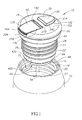
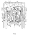
- the stopper 10 may be selectively transitioned by a user between a closed configuration (illustrated in Figures 1 and 2 ) and an open configuration (illustrated in Figure 3 ). Thus, the stopper 10 may be selectively opened and closed by a user.
- the container 12 has a hollow interior portion 15 for storing liquid or semi-liquid contents. Non-limiting examples of liquid or semi-liquid contents stored by the container include beverages, soups, and the like.
- the stopper 10 When the stopper 10 is opened, the contents residing in the interior portion 15 of the container 12 may flow therefrom through the stopper 10.
- the stopper 10 When the stopper 10 is closed, the contents residing in the interior portion 15 of the container 12 are sealed therein by the stopper 10.
- the stopper 10 is configured to be attached to a rim portion 16 of the container 12 by a connector portion 17.
- the rim portion 16 has threads 18 formed on its inside surface 20.
- the rim portion 16 also includes an inwardly extending sealing member 21 located below the threads 18.
- the connector portion 17 of the stopper 10 includes outside threads 22 disposed about a lower portion 24 of an outer surface 26 of an outer body 40 of the stopper 10.
- the threads 22 of the connector portion 17 are configured to threadedly engage the threads 18 of the rim portion 16 for removable engagement therewith.
- an inverted cup 30, mug, bowl, and the like may be coupled to the rim portion 16 of the container 12 over the stopper 10.
- the stopper 10 is housed inside the inverted cup 30, which must first be removed before the stopper 10 can be selectively opened by the user.
- the inverted cup 30 has a bottom portion 32 with an inside surface 34 spaced from an upper end of the stopper 10.
- the stopper 10 has an interior portion 36 defined at least in part by the outer body 40.
- the stopper 10 also includes an inner body 42 nested inside the outer body 40, an annular sealing member 43 (e.g., an o-ring) sandwiched between the outer and inner bodies 40 and 42 and forming a liquid tight seal therebetween, and a valve assembly 44 having internal components 46 disposed inside the interior portion 36 of the outer body 40, and a valve member 48 having a shaft portion 50 and a plug portion 54 external to the outer body 40.
- the shaft portion 50 having a proximal end 52 engaging the internal components 46 of the valve assembly 44 and a distal end 56 coupled to the plug portion 54 external to the outer body 40.
- the stopper 10 also includes a top cover 60 coupled to the inner body 40 and covering both the outer and inner bodies 40 and 42.
- the stopper 10 also has an annular seal 64 disposed between the plug portion 54 of the valve member 48 and the outer body 40.
- the annular seal 64 forms a liquid tight seal between the plug portion 54 of the valve member 48 and the outer body 40 when the stopper 10 is in the closed configuration (illustrated in Figures 1 and 2 ).
- the plug portion 54 of the valve member 48 is spaced from the annular seal 64 to permit the flow of the contents of the container 12 into and out of the interior portion 36 of the stopper 10.
- the annular seal 64 also engages (and may be compressed by) the inwardly extending sealing member 21 to form a liquid tight seal between the stopper 10 and the rim portion 16 of the container 12.
- the valve assembly 44 is actuated by an externally accessible and manually operated pushbutton 70 coupled to an elongated lever member 74 pivotally mounted to the inner body 42.
- the lever member 74 pivots between an open position (illustrated in Figure 3 ) in which the stopper 10 is open and the contents of the container 12 may exit therefrom through the stopper 10 and a closed position (illustrated in Figures 1 and 2 ) in which the stopper 10 is closed and the contents of the container 12 are retained inside the container 12 by the stopper 10.
- Figure 4 provides an exploded view of the components of the stopper 10.
- the components of the valve assembly 44 are omitted from Figure 4 .
- Explodeds view of the components of the valve assembly 44 (illustrated with the lever member 74) are provided in Figures 13 and 14 .
- Each of the components illustrated in Figure 4 are described in the following sections.
- the pushbutton 70 is selectively positionable in both a depressed, open position (see Figure 3 ) and a raised, closed position (see Figures 1 and 2 ).
- the pushbutton 70 travels been the open and closed positions along a substantially linearly path of travel along a travel direction (identified by double headed arrow "A1" in Figures 2 and 3 ) relative to the top cover 60.
- the pushbutton 70 has a top portion 100 against which the user pushes to pivot the lever member 74, a side portion 102 extending downwardly from the top portion 100, a bottom portion 104 opposite the top portion 100, and a pair of spaced apart downwardly extending connector portions 106A and 106B disposed along the bottom portion 104.
- the side portion 102 is implemented as a single continuation sidewall 108. However, this is not a requirement, and embodiments in which the side portion 102 includes two or more connected or disconnected sidewalls (not shown) are also within the scope of the present teachings.
- the connector portions 106A and 106B couple the pushbutton 70 to the lever member 74.
- the connector portion 106A includes a slot 112A and connector portion 106B includes a slot 112B.
- the slots 112A and 112B are spaced apart and juxtaposed with one another.
- the slots 112A and 112B each extend in a direction substantially orthogonal to the direction of travel (identified by double headed arrow "A1" in Figures 2 and 3 ) of the pushbutton 70 relative to the top cover 60 when the pushbutton is depressed by the user to open the stopper 10.
- the pushbutton 70 includes one or more internal support members.
- the pushbutton 70 includes a transverse support member 118 extending under the top portion 100 and between opposite portions of the continuation sidewall 108.
- the lever member 74 is selectively positionable in both an open position (see Figure 3 ) and a closed position (see Figures 1 and 2 ) by the pushbutton 70.
- the lever member 74 has an external portion 130 and an internal portion 132.
- the lever member 74 has a bent shape with an inside angle "A2" defined between the external portion 130 and the internal portion 132.
- the angle "A2" has an apex "B" at the intersection of the external and internal portions 130 and 132.
- the external portion 130 When assembled inside the stopper 10, the external portion 130 is accessible from outside the stopper 10 and the internal portion 132 is disposed inside the stopper.
- the external portion 130 includes a tapered flap portion 136 having an underside 138 with a guide follower portion 140, a proximal portion 142 adjacent the internal portion 132 and a distal portion 144 opposite the proximal portion.
- the flap portion 136 may be tapered so that its thickest portion is along its proximal portion 142 and its thinnest portion is along its distal portion 144.
- the guide follower portion 140 extends downwardly from the underside 138 of the flap portion 136 toward the inner body 42 of the stopper 10 and is not exposed when the lever member 74 is in the closed position. However, as may be viewed in Figure 3 , the guide follower portion 140 may be at least partially visible to the user when the lever member 74 is in the open position. The guide follower portion 140 may help orient the lever member 74 relative to the top cover 60 and may help guide the lever member 74 relative to the inner body 42 when the lever member 74 is transitioned between the open and closed positions. In the embodiment illustrated in Figures 5 and 6 , the guide follower portion 140 is implemented as a continuous wall curved along both its length and height. Further, the guide follower portion 140 is located adjacent to the apex "B" of the angle "A2.”
- the internal portion 132 includes a support platform 148 having a curved intermediate portion 150 flanked by a curved proximal edge portion 156 coupled to the external portion 130, and a free distal edge portion 158 opposite the proximal edge portion 156 and terminated by a rounded cam follower portion 160.
- the internal portion 132 also includes a transverse pivot pin 162 coupled to the support platform 148 between the curved proximal edge portion 156 and the curved intermediate portion 150.
- the transverse pivot pin 162 has a first end portion 164A opposite a second end portion 164B.
- the transverse pivot pin 162 is spaced from the apex "B" of the angle "A2" toward the free distal edge portion 158.
- the transverse pivot pin 162 includes an intermediate portion 166 located between the first and second end portions 164A and 164B.
- the intermediate portion 166 may have a larger diameter than the first and second end portions 164A and 164B.
- the internal portion 132 includes a support member 168 coupled to the curved intermediate portion 150 and positioned to provide lateral support to the transverse pivot pin 162.
- the internal portion 132 also includes a connector portion 170 coupled to the free distal edge portion 158 of the support platform 148.
- the connector portion 170 includes an elongated transverse pivot pin 174 coupled to the support platform 148 by a support member 176.
- the transverse pivot pin 174 is shorter in length than the transverse pivot pin 162.
- the transverse pivot pin 174 includes an intermediate portion 180 between the first and second end portions 178A and 178B.
- the intermediate portion 180 may be configured to be too large to be received inside the slots 112A and 112B to limit the lateral movement to of the lever member 74 relative to the pushbutton 70.
- the intermediate portion 180 of the transverse pivot pin 174 is flanked by the connector portions 106A and 106B of the pushbutton 70.
- the transverse pivot pin 174 pivots and slides longitudinally within the spaced apart slots 112A and 112B when the lever member 74 is moved between the open and closed positions.
- the support member 176 is configured to adequately space the transverse pivot pin 174 from the support platform 148 to permit the transverse pivot pin 174 to pivot within the spaced apart slots 112A and 112B without the occurrence of undesirable engagement between the sidewall 108 of the pushbutton 70 and the support platform 148 of the lever member 74.
- the top cover 60 is generally disk shaped and has a downwardly curving upper surface 202 with a generally circular perimeter portion "P1" and a downwardly extending sidewall 204 extending circumferentially about the upper surface 202 and along the perimeter portion "P1."
- a first aperture 210 is formed in the upper surface 202 through which the contents of the container 12 may flow when the lever member 74 is in the open position (see Figure 3 ).
- a second aperture 214 spaced apart from the first aperture 210 is formed in the upper surface 202. The second aperture 214 is configured to receive the pushbutton 70 and permit it to be depressed by the user for the purposes of pivoting the lever member 74 into the open position.
- the first and second apertures 210 and 214 each have a perimeter portion "P2" and "P3,” respectively.
- the perimeter portion "P2" of the first aperture 210 has a relieved portion 218 adjacent the perimeter portion "P1" of the upper surface 202.
- the perimeter portion "P2" of the second aperture 214 has a curved portion 220 opposite a substantially linear portion 222.
- a pair of inwardly extending guide walls 224A and 224B are positioned opposite one another along the perimeter portion "P2" of the first aperture 210.
- the guide wall 224A has a notch 225A formed along its distal edge 226A and the guide wall 224B has a notch 225B formed along its distal edge 226B juxtaposed with the notch 225A across the first aperture 210.
- the notches 225A and 225B are disposed to receive a portion of the first and second end portions 164A and 164B, respectively, of the transverse pivot pin 162 of the lever member 74 therein, when the stopper 10 is assembled. In this manner, the notches 225A and 225B help maintain the proper positioning of the lever member 74 relative to the top cover 60 and the inner body 42 (see Figure 4 ).
- the top cover 60 also has an inwardly extending first guide wall portion 227 and a second guide wall portion 228, each adjacent to at least a portion of the perimeter portion "P3" of the second aperture 214.
- first guide wall portion 227 is curved about the curved portion 220 of the perimeter portion "P3" of the second aperture 214 and the second guide wall portion 228 is substantially linear extending along the substantially linear portion 222 (see Figures 5 and 6 ) of the perimeter portion "P3" of the second aperture 214.
- the side portion 102 of the pushbutton 70 is adjacent the first and second guide wall portions 227 and 228.
- the first guide wall portion 227, and the second guide wall portion 228 help guide the pushbutton 70 as it is transitioned between the open and closed positions limiting the lateral movement of the pushbutton laterally relative to the top cover 60 and the internal structures of the stopper 10.
- the first guide wall portion 227 terminates in a shelf portion 230.
- a portion of the sidewall 108 adjacent the bottom portion 104 of the pushbutton 70 rests upon the shelf portion 230, which limits the inward path of travel of the pushbutton 70.
- the second guide wall portion 228 includes a central notch 232 along its lower edge 234.
- the central notch 232 is configured to allow the support member 168 of the connector portion 170 of the lever member 74 to pass into and out of the central notch 232 as the lever member 74 is pivoted into and out of the open position to prevent interference between the second guide wall portion 228 and the lever member 74.
- the flap portion 136 of the lever member 74 When the lever member 74 is in the closed position (see Figures 1 and 2 ), the flap portion 136 of the lever member 74 is received inside the first aperture 210 in the top cover 60 and closes the first aperture 210, with the distal portion 144 of the flap portion 136 being located adjacent to the relieved portion 218 of the perimeter portion "P2" of the first aperture 210.
- the internal portion 132 of the lever member 74 extends away from the first aperture 210 and toward the inner body 42 with the transverse pivot pin 162 resting on and being supported by the inner body 42 (see Figure 2 ) inside the stopper 10.
- the top surface 100 of the pushbutton 70 and an exposed portion 240 of the side portion 102 extend upwardly from the upper surface 202 of the top cover 60 through the second aperture 214.
- the connector portions 106A and 106B of the pushbutton 70 are coupled to the connector portion 170 of the lever member 74.
- the lever member 74 and the pushbutton 70 are transitioned from the open position to the closed position by pressing the lever member 74 toward the top cover 60.
- the lever member 74 may be pressed into the closed position by the user, or the inverted cup 30 (see Figure 2 ) when the inverted cup is attached to the rim portion 16 of the container 12 over the stopper 10.
- the inside surface 34 of the bottom portion 32 of the inverted cup 30 will bear against the distal portion 144 of the flap portion 136 pressing it toward the top cover 60 and causing it to transition into the closed position.
- the downwardly extending sidewall 204 along the perimeter portion "P1" of the top cover 60 has an inwardly extending projection 244 defining a channel 246 below the upper surface 202.
- the projection 244 and the channel 246 are configured to removably couple the top cover 60 to the inner body 42 (see Figures 2-4 ).
- a radially extending guide member 248 extends between the first guide wall portion 227 and the downwardly extending sidewall 204.
- the inner body 42 has an interior portion 256 housing various component of the valve assembly 44 (see Figures 13 and 14 ) and through which the contents of the container 12 (see Figures 1 and 2 ) flow when the stopper 10 (see Figures 1-3 ) is in the open configuration (illustrated in Figure 3 ).
- the interior portion 256 is defined by an outer wall 258 having four segments: a top segment 260-1, a first middle segment 260-2, a second middle segment 260-3, and a bottom segment 260-4.
- the four segments 260-1, 260-2, 260-3, and 260-4 each have a generally circular cross-sectional shape with diameters that decrease from section 260-1 to section 260-4.
- the top segment 260-1 includes an upper portion 262 having an outwardly extending pour spout 264.
- the sidewall 204 (see Figures 5 and 6 ) of the top cover 60 is coupled to the upper portion 262 of the top segment 260-1 of the inner body 42, with the relieved portion 218 (see Figures 2 and 3 ) being located adjacent to the pour spout 264.
- the pour spout 264 extends upwardly and outwardly through the first aperture 210 when the top cover 60 is coupled to the inner body 42.
- the upper portion 262 of the top segment 260-1 has a plurality of upwardly extending spaced apart fingers 266 each having an outwardly and radially extending projection 268. Interstices 270 are defined between adjacent fingers 266.
- the fingers 266 flex inwardly to allow the radially extending projections 268 to pass over the inwardly extending projection 244 (see Figure 6 ) of the top cover 60. After passing over the inwardly extending projection 244, the fingers 266 bias the projections 268 outwardly radially into the channel 246 (see Figure 6 ) above the projection 244.
- the inwardly extending projection 244 provides a barrier preventing the removal of the outwardly extending projections 268 from the channel 246 thereby maintaining the top cover 60 in engagement with the inner body 42. In this manner, the outwardly extending projections 268 of the fingers 266 snap into the channel 246 above the projection 244 to securely attach the top cover 60 to the top segment 260-1 of the inner body 42.
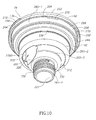
- Figure 10 illustrates a sub-assembly of the stopper 10 (see Figures 1-3 ) including the top cover 60 coupled to the inner body 42.
- the outwardly radially extending projections 268 of the fingers 266 extend far enough way from the outer wall 258 of the inner body 42 to space the projection 244 and the sidewall 204 of the top cover 60 away from the outer wall 258 of the inner body 42, thereby permitting air to flow into the interior portion 256 (see Figures 8 and 9 ) through the interstices 270.
- the interstices 270 may optionally extend along the outer wall 258 of the inner body 42 to a location below the inwardly extending projection 244 when the top cover 60 is coupled to the inner body 42, allowing air to flow into the interstices 270.
- the interstices 270 when the inner body 42 is nested inside the outer body 40, the interstices 270 (see Figures 8 and 9 ) are in open communication with the interior portion 36 (see Figures 2 and 3 ) defined at least in part by an outer body 40.
- the interstices 270 are in open communication with a portion 271 of the interior portion 36 located above the annular sealing member 43 (see Figures 2 and 3 ). Air may flow between the top cover 60 and the outer body 40 from the environment outside the stopper 10 into the portion 271 of the interior portion 36 of the stopper 10.
- one of the interstices 270 is configured to receive the radially extending guide member 248 (see Figure 7 ) of the top cover 60 and limit its circumferential movement relative to the inner body 42.
- a first shoulder 274-1 is provided at the intersection of the top segment 260-1 and the first middle segment 260-2
- a second shoulder 274-2 is provided at the intersection of the first middle segment 260-2 and the second middle segment 260-3
- a third shoulder 274-3 is provided at the intersection of the second middle segment 260-3 and the bottom segment 260-4.
- the inner body 42 Inside the interior portion 256, the inner body 42 includes a pair of spaced apart upright support walls 278A and 278B flanking the pour spout 264 of the top segment 260-1 and an upright transverse dividing wall 280 extending between the upright support walls 278A and 278B.
- the upright support walls 278A and 278B and the upright transverse dividing wall 280 extend upwardly from the third shoulder 274-3 and terminate in the top segment 260-1.
- the upright support walls 278A and 278B each have a lever support section 282A and 282B, respectively, and an air flow section 284A and 284B, respectively.
- the lever support sections 282A and 282B each have a flap support portion 286A and 286B, respectively, and a pivot pin support portion 288A and 288B, respectively.
- the flap support portions 286A and 286B are separated from the pivot pin support portions 288A and 288B by the dividing wall 280.
- the flap support portions 286A and 286B extend along opposite sides of the pour spout 264 and terminate at the dividing wall 280.
- the underside 138 of the flap portion 136 of the lever member 74 rests upon the flap support portions 286A and 286B of the lever support sections 282A and 282B.
- the flap support portions 286A and 286B may be tapered from the dividing wall 286 to the pour spout 264, having thicker portions 290A and 290B, respectively, adjacent the pour spout 264.
- the underside 138 of the flap portion 136 may form a liquid tight seal with the flap support portions 286A and 286B; however, this is not a requirement. Whether the contents of the container 12 (see Figures 1-3 ) flow through the stopper 10 is determined by whether the plug portion 54 of the valve member 48 is pressed against the annular seal 64 or spaced therefrom. Thus, the flap portion 136 may play no role in maintaining the contents of the container 12 therein. Therefore, a liquid tight seal need not be formed between the underside 138 of the flap portion 136 and the flap support portions 286A and 286B. Instead, the flap portion 136 may help prevent contaminants from entering the interior portion 36 of the stopper 10 through the first aperture 210 of the top cover 60.
- the pivot pin support portion 288A of the upright support wall 278A has a notch 292A spaced from the dividing wall 280 and located near the center of the interior portion 256 of the inner body 42.
- the pivot pin support portion 288B of the lever support section 282B of the upright support wall 278B has a notch 292B spaced from the dividing wall 280 and located near the center of the interior portion 256 of the inner body 42.
- the notches 292A and 292B are configured to receive the first and second end portions 164A and 164B, respectively, of the transverse pivot pin 162 of the lever member 74. When the stopper 10 is assembled, the first and second end portions 164A and 164B of the transverse pivot pin 162 reside inside the notches 292A and 292B, respectively, and pivot therein relative to the inner body 42.
- the lever support sections 282A and 282B extends upwardly into the top segment 260-1 further than the air flow sections 284A and 284B.
- air flow gaps 296A and 296B are defined between the top cover 60 (see Figure 4 ) and the air flow sections 284A and 284B, respectively.
- the air flow sections 284A and 284B may not contact the outer wall 258 within the top segment 260-1 above the first shoulder 274-1, thereby defining a first gap 298A between the air flow section 284A and the outer wall 258 above the first shoulder 274-1 and a second gap 298B between the air flow section 284B and the outer wall 258 above the first shoulder 274-1.
- the upright support walls 278A and 278B divide the interior portion 256 into three regions “R1,” “R2,” and “R3.” Within the first and second middle segments 260-2 and 260-3, the three regions “R1,” “R2,” and “R3” are separated from one another by the upright support walls 278A and 278B. However, within the top segment 260-1, the three regions “R1,” “R2,” and “R3” are in communication with one another via the air flow gaps 296A and 296B defined between the top cover 60 (see Figure 4 ) and the lever support sections 282A and 282B and the gaps 298A and 298B (see Figure 15 ) between the air flow sections 284A and 284B and the outer wall 258.
- the regions “R1,” and “R3,” flank the "R2” and are essentially voids for storing air received from the environment outside the stopper 10 (see Figures 1-3 ) via the interstices 270.
- the dividing wall 280 bifurcates the region "R2" of the interior portion 256 of the inner body 42 into a fluid flow channel 300 and a valve housing portion 306.
- a first aperture 310 is formed in the second shoulder 274-2 within the fluid flow channel 300 portion of the region "R2" of the interior portion 256 of the inner body 42. In the embodiment illustrated, the first aperture 310 extends into the second middle segment 260-3 and the third shoulder 274-3.
- the flap support portion 286A and 286B of the lever support sections 282A and 282B, respectively, of the upright support walls 278A and 278B, respectively, are adjacent the fluid flow channel 300 of the region "R2.”
- the pivot pin support portion 288A and 288B of the lever support sections 282A and 282B, respectively, of the upright support walls 278A and 278B, respectively, are adjacent the valve housing portion 306 of the region "R2.”
- the air flow section 284A and 284B of the upright support walls 278A and 278B, respectively, are adjacent the valve housing portion 306 of the region "R2.”
- air is allowed to flow into the valve housing portion 306 through the air flow gaps 296A and 296B are defined between the top cover 60 (see Figure 4 ) and the air flow sections 284A and 284B, respectively and the gaps 298A and 298B (see Figure 15 ) between the air flow sections 284A and 284B and the outer wall 258.
- a second aperture 312 is formed in the second shoulder 274-2 within the valve housing portion 306 of the region “R2" of the interior portion 256 of the inner body 42.
- the second aperture 312 permits air to flow from inside the region “R2" of the interior portion 256 of the inner body 42 into the outer body 40.
- the valve assembly 44 When the valve assembly 44 is open, the air inside the outer body 40 may flow from the outer body 40 into the container 12.
- the flow of air through the stopper 10 see Figures 1-3 ) into the container 12 (see Figures 1 and 2 ) allow the contents of the container 12 to flow more readily through the fluid flow channel 300 of the region "R2" when the stopper is open.
- the guide follower portion 140 of the lever member 74 is positioned adjacent to the transverse dividing wall 280 between the upright support walls 278A and 278B (see Figures 8 and 9 ) and extends into the valve housing portion 306 (see Figures 8 and 9 ) of the region "R2.” Further, the support platform 148 of the internal portion 132 of the lever member 74 extends into the valve housing portion 306 (see Figures 8 and 9 ) of the region "R2" when the lever member 74 is in both the open and closed positions.
- the guide follower portion 140 is spaced from the transverse dividing wall 280 and the upright support walls 278A and 278B (see Figures 8 and 9 ) and does not typically contact these structures when transitioning between the open and closed positions. However, if sufficient laterally directed force is applied to the lever member 74, lateral and radial movement of the guide follower portion 140 of the lever member 74 may be constrained by the transverse dividing wall 280 and the upright support walls 278A and 278B (see Figures 8 and 9 ).
- valve housing portion 306 portion of the region "R2" of the interior portion 256 of the inner body 42 includes a centrally located valve housing 320 for at least a portion of the components of the valve assembly 44.
- the valve housing 320 includes a generally cylindrically shaped sidewall 324 with a longitudinally extending guide groove 328 formed therein.
- the bottom segment 260-4 of the outer wall 258 includes a connector portion 330 configured to removably couple the inner body 42 to the outer body 40 (see Figures 2 and 3 ).
- the connector portion 330 has outside threads 332.
- the first middle segment 260-2 of the outer wall 258 includes an outwardly and radially extending annular projection 338 configured to maintain the annular sealing member 43 (e.g., an O-ring) against the outer wall 258 of the inner body 42.
- annular sealing member 43 e.g., an O-ring
- the outer body 40 has an interior portion 350 defined by an inside surface 352 of an outer wall 354 having three segments: a top segment 360-1, a middle segment 360-2, and a bottom segment 360-3.
- the three segments 360-1, 360-2, and 360-3 each have a generally circular cross-sectional shape with diameters that decrease from section 360-1 to section 360-3.
- the outer wall 354 has an outside surface 361 opposite the inside surface 352.
- the connector portion 17 (see Figures 1-3 ) of the stopper 10 is formed along the outside surface 361 of the middle segment 360-2 of the outer wall 354. As illustrated in Figure 11 , the outside threads 22 extend around the middle segment 360-2 of the outer wall 354.
- first shoulder 362-1 is provided at the intersection of the top segment 360-1 and the middle segment 360-2, and a second shoulder 362-2 is provided at the intersection of the middle segment 360-2 and the bottom segment 360-3.
- first shoulder 362-1 includes an annular groove 365 configured to receive a portion of the annular sealing member 43 (see Figures 2-4 ) disposed on the outside wall 258 (see Figures 8 and 9 ) of the first middle segment 260-2 (see Figures 8 and 9 ) above the radially extending annular projection 338 (see Figures 8 and 9 ) of the inner body 42.
- the annular sealing member 43 (optionally received inside the annular groove 365 formed in the first shoulder 362-1) forms a liquid tight seal between the inner and outer bodies 42 and 40.
- a seal-engaging surface 364 is formed in the outside surface 361 of the outer wall 354 at the intersection of the middle segment 360-2 and the bottom segment 360-3.
- the seal-engaging surface 364 is configured to abut an upper face of the annular seal 64 (see Figures 2 and 3 ) when the stopper 10 is assembled.
- the outer body 40 has an internal connector portion 368 located approximately centrally within the interior portion 350 of the outer body 40.
- the internal connector portion 368 extends upwardly from the bottom segment 360-3 into at least a portion of the middle segment 360-2.
- At least one radially extending connecting member 370 couples the internal connector portion 368 to the inside surface 352 of the outer wall 354 in the bottom segment 360-3.
- At least one opening 372 is formed in the connecting member 370 (or alternatively located between adjacent connecting members).
- the internal connector portion 368 is configured to be removably coupled to the connector portion 330 (see Figures 8 and 9 ) of the bottom segment 260-4 of the outer wall 258 of the inner body 42.
- the internal connector portion 368 of the outer body 40 is generally cylindrically shaped having an open top end portion 376 of a continuous sidewall 378.
- the internal connector portion 368 may have a partially closed bottom end portion 380 with a substantially centrally located through-hole 382 formed therein.
- the sidewall 378 has an inside surface 384 with inside threads 386 disposed thereon and configured to engage and threadedly mate with the outside threads 332 (see Figures 8 and 9 ) of the connector portion 330 of the inner body 42.
- the bottom segment 360-3 of the outer wall 354 includes an outwardly and radially projecting lower portion 390 configured to extend into a recessed portion of the annular seal 64 (see Figures 8 and 9 ) to hold the annular seal 64 on the bottom segment 360-3 of the outer wall 354 of the outer body 40.
- a channel 392 is defined between the projecting lower portion 390 and the seal-engaging surface 364 adjacent the middle segment 360-2.
- the inside surface 352 of the bottom segment 360-3 includes a lower recessed portion 398.
- the annular seal 64 is configured to be coupled to the bottom segment 360-3 of the outer wall 354 of the outer body 40 and to form a liquid tight seal between the outer body 40 and the plug portion 54 (see Figure 2 ) of the valve member 48 when the stopper 10 is in the closed configuration (illustrated in Figures 1 and 2 ).
- the annular seal 64 has an annular body portion 400 constructed from rubber, rubber, resilient plastic, elastomers, any other suitable material known in the art, combinations thereof, and the like.
- the annular body portion 400 defines a generally circular central opening 402.
- the annular body portion 400 has an upper surface 404 configured to engage the seal-engaging surface 364 (see Figure 11 ) of the outer body 40 to form a liquid tight seal therewith when the stopper 10 (see Figures 1-3 ) is assembled.
- the annular body portion 400 has an inwardly and radially extending projection 408 configured to be received inside the channel 392 (see Figure 11 ) defined between the projecting lower portion 390 (see Figure 11 ) and the seal-engaging surface 364 (see Figure 11 ) of the outer body 40.
- the annular seal 64 has an open generally U-shaped channel 410 configured to receive the projecting lower portion 390 (see Figure 11 ) of the outer body 40.
- the channel 410 is defined by the projection 408, a downwardly extending sidewall 414, and an inwardly extending lower sealing portion 416 having a lower surface 418.
- the lower surface 418 engages and forms a liquid tight seal with the plug portion 54 (see Figure 2 ) of the valve member 48 when the stopper 10 is in the closed configuration (illustrated in Figures 1 and 2 ).
- a downwardly extending sealing projection 420 is formed along the lower surface 418 of the lower sealing portion 416.
- the sealing projection 420 is annular, concentric with the annular body portion 400, and extends continuously around the outside surface 418 of the sealing portion 416.
- the sealing projection 420 bears against and may be compressed by the plug portion 54 (see Figure 2 ) of the valve member 48 when the stopper 10 is in the closed configuration (illustrated in Figures 1 and 2 ) to provide a liquid tight seal between the annular seal 64 and the plug portion 54 (see Figure 2 ).
- the inwardly extending lower sealing portion 416 is terminated by an upwardly extending gripping projection 424 configured to be received inside the lower recessed portion 398 (see Figure 11 ) of the bottom segment 360-3 of the outer wall 354 of the outer body 40.
- the annular body portion 400 wraps around and encases the outside surface 361 of the bottom segment 360-3 (see Figure 11 ) and a portion of the inside surface 352 of the outer wall 354 of the outer body 40 to hold the annular seal 64 securely on the outer body 40.
- the annular body portion 400 has an outer sealing portion 430 configured to engage the inwardly extending sealing member 21 located below the threads 18 of the rim portion 16 of the container 12.
- the outer sealing portion 430 is spaced from and extends along the downwardly extending sidewall 414 defining a channel 432 therebetween.
- the outer sealing portion 430 is coupled to the downwardly extending sidewall 414 adjacent the inwardly and radially extending projection 408 by an inwardly extending portion 434.
- the channel 432 is open along its bottom portion 436 opposite the inwardly extending portion 434.
- the outer sealing portion 430 deflects into the channel 432 when inwardly directed forces are applied to the outer sealing portion 430 by the inwardly extending sealing member 21 (see Figures 1 and 2 ) of the container 12 but has sufficient resiliency to maintain a liquid tight seal therewith.
- the components of an exemplary implementation of the valve assembly 44 and the lever member 74 are illustrated in Figures 13 and 14 .
- the valve assembly 44 includes the valve member 48, a link member 510 having the cam surface 200 formed thereon, a washer or cap 514, a biasing member 516 (e.g., a coil spring), and a collar 518.
- the valve assembly 44 is a poppet type valve opened by the action of a cam (i.e., the cam follower portion 160 of the lever member 74) and closed by the action of the biasing member 516.
- the valve member 48 includes the shaft portion 50 and the plug portion 54, the shaft portion 50 being substantially orthogonal to the plug portion 54 and centrally located.
- the shaft portion 50 Opposite the plug portion 54 and on its proximal end 52, the shaft portion 50 includes a connector portion 520 having a cone-shaped key member 524 disposed above an annular circumferential groove 528 extending around the proximal end 52 of the shaft portion.
- the collar 518 is configured to be disposed about the shaft portion 50 of the valve member 48 between the connector portion 520 and the distal end 56 coupled to the plug portion 54.
- the substantially centrally located through-hole 382 (see Figure 11 ) formed in the partially closed bottom end portion 380 of the internal connector portion 368 of the outer body 40 is configured to receive the shaft portion 50 of the valve member 48 and permit it to travel therethrough.
- the through-hole 382 (see Figure 11 ) is not large enough to permit the collar 518 to pass therethrough.
- the collar 518 has an upright open-ended hollow cylindrical section 534 having a sidewall 535 with an upper portion 536 opposite a lower portion 537 and a base portion 538 coupled to the lower portion 537 of the hollow cylindrical section 534.
- the base portion 538 has a bottom inside surface 540 and an upwardly extending sidewall 544 spaced from the sidewall 535 of the hollow cylindrical section 534 and extending upwardly from the bottom inside surface 540 along the lower portion 537 of the sidewall 535 of the hollow cylindrical section 534.
- the biasing member 516 is implemented as a coil spring 550 having an upper end portion 554 opposite a lower end portion 556.
- the biasing member 516 is configured to be disposed about the hollow cylindrical section 534 with its lower end portion 556 resting on the bottom inside surface 540 of the base portion 538.
- the sidewall 544 of the base portion 538 retains the lower end portion 556 of the biasing member 516 in proper alignment with respect to the valve member 48 and prevents the lower end portion 556 from gaining entry into the through-hole 382 (see Figure 11 ) formed in the partially closed bottom end portion 380 of the internal connector portion 368 of the outer body 40.
- the biasing member 516 may extend beyond the collar 518 to extend along a portion of the shaft portion 50 of the valve member 48 below the annular groove 528 (illustrated in Figures 2 and 3 ).
- the cap 514 may be generally disk-shaping having an upper platform 562 with a top side 563 opposite an underside 564 and sidewall 566 extending circumferentially along and downwardly from the platform 562.
- the upper platform 562 has a connector portion 568 with a keyway portion 570 configured to receive and retain the cone-shaped key member 524 of the shaft portion 50 of the valve member 48.
- One or more slots 272 may intersect with and extend from the keyway portion 570 to allow the upper platform 562 to flex to allow the keyway portion 570to receive the cone-shaped key member 524 of the valve member 48.
- portions 580 of the upper platform 562 along the keyway portion 570 are received inside the annular groove 528 below the key member 524 and maintain the cap 514 on the shaft portion 50 of the valve member 48.
- the key member 524 and the keyway portion 570 may snap together to form a snap fit.
- the upper end portion 554 of the coil spring 550 abuts the underside 564 of the upper platform 562 and is surrounded by the downwardly extending sidewall 566.
- the coil spring 550 is confined between the underside 564 of the upper platform 562 of the cap 514 and the bottom inside surface 540 of the base portion 538 of the collar 518.
- the link member 510 is configured to engage the top side 563 of the cap 514 when the cap is inside the valve housing 320 (see Figures 2 and 3 ).
- the link member 510 includes the cam surface 200 disposed on a closed upper end portion 578 of an upright hollow cylindrical section 582 having a sidewall 584 extending downwardly from the closed upper end portion 578 and an open lower portion 586 opposite the closed upper end portion 578.
- the open lower portion 586 abuts the top side 563 of the cap 514 to transfer any downwardly directed forces applied to the link member 510 to the cap 514.
- the cam follower portion 160 of the lever member 74 bears against the cam surface 200 of the link member 510 when the lever member is pivoted from the closed position (see Figures 1 and 2 ) to the open position (see Figure 3 ).
- the cam surface 200 includes a relieved portion 590.
- the cam follower portion 160 of the lever member 74 travels along the cam surface 200 toward the relieved portion 590.
- the lever member 74 is fully in the open position (see Figure 3 ), when the cam follower portion 160 is fully received inside the relieved portion 590.
- the relieved portion 590 is configured to maintain the lever member 74 in the fully open position until sufficient downward force is applied to the flap portion 136 of the lever member 74 to force the cam follower portion 160 from the relieved portion 590.
- the cap 514, the collar 518, the link member 510, and the biasing member 516 are suitably sized and shaped to move (e.g., slide) within the valve housing 320 of the inner body 42 when the inner body 42 is coupled to the outer body 40.
- the valve housing 320 helps guide and limit the travel path of the cap 514 within the interior portion 36 of the stopper 10.
- the link member 510 includes a key projection 594 extending along the sidewall 584 of the cylindrical section 582 between the closed end portion 578 and the open end portion 586.
- the key projection 594 is configured to be received inside the guide groove 328 of the sidewall 324 of the valve housing 320 and slide therein along at least a portion of the length of the guide groove. Engagement between the key projection 594 and the guide groove 328 ensures the cam surface 200 is oriented properly relative to the cam follower portion 160 of the lever member 74 for proper engagement therebetween.
- the contents of the container 12 may flow from the interior portion 15 (see Figures 1 and 2 ) of the container through the fluid flow channel 300.
- the contents of the container 12 enter the outer body 40 through the opening(s) 372.
- the contents enter the fluid flow channel 300 via the first aperture 310.
- the contents flow through the fluid flow channel 300 toward the pour spout 264 and exit the fluid flow channel 300 through the first aperture 210 guided by the pour spout 264.
- air may flow into the interior portion 15 (see Figures 1 and 2 ) of the container 12 (see Figures 1 and 2 ) through the valve housing portion 306.
- air flows between the top cover 60 and the outer body 40 into a portion 271 (see Figures 2 and 3 ) of the interior portion 36 located above the annular sealing member 43 (see Figures 2 and 3 ).
- air flows into the regions "R1" and “R3" of the interior portion 256 of inner body 42 through the interstices 270.
- air may flow into the valve housing portion 306 of the region "R2" of the interior portion 256 of inner body 42 through the interstice 270A.
- Air then flows from the regions “R1" and “R3” into the valve housing portion 306 of the region “R2” via the air flow gaps 296A and 296B, and air flow gaps 298A and 298B (see Figure 15 ).
- the air flows through the second aperture 312 into the outer body 40.
- air may enter the interior portion 15 (see Figures 1 and 2 ) of the container 12 (see Figures 1 and 2 ) through the opening(s) 372.
- the annular seal 64 maybe coupled to the bottom segment 360-3 of the outer wall 354 of the outer body 40. Then, the shaft portion 50 of the valve member 48 is inserted upwardly into the centrally located through-hole 382 (see Figure 11 ) of the bottom end portion 380 (see Figure 11 ) of the internal connector portion 368 of the outer body 40.
- the collar 518 is disposed about the shaft portion 50 of the valve member 48 between the connector portion 520 and the distal end 56 coupled to the plug portion 54.
- the collar 518 may rest upon partially closed bottom end portion 380 (see Figure 11 ) of the internal connector portion 368 of the outer body 40 or alternately be disposed inside the through-hole 382 (see Figure 11 ).
- the through-hole 382 is not large enough to permit the collar 518 to pass therethrough.
- the biasing member 516 is disposed around the collar 518 with its lower end portion 556 resting on the bottom inside surface 540 of the base portion 538. Then, the cone-shaped key member 524 (see Figure 13 ) of the shaft portion 50 of the valve member 48 is inserted in the keyway portion 570 (see Figure 13 ) of the cap 514 and the portions 580 (see Figure 13 ) of the upper platform 562 along the keyway portion 570 are received inside the annular groove 528 below the key member 524 (see Figure 13 ) to maintain the cap 514 on the shaft portion 50 of the valve member 48.
- the biasing member 516 abuts the underside 564 of the upper platform 562 and is surrounded by the downwardly extending sidewall 566 of the cap 514. Thus, the biasing member 516 may be confined between the underside 564 of the upper platform 562 of the cap 514 and the bottom inside surface 540 of the base portion 538 of the collar 518.
- the annular sealing member 43 (e.g., an o-ring) is disposed about the first middle segment 260-2 of the outer wall 258 of the inner body 42 above the outwardly and radially extending annular projection 338. Then, the inner body 42 is nested inside the outer body 40. As the inner body 42 is inserted into the outer body 40, the shaft portion 50 of the valve member 48 with the collar 518, the biasing member 516, and the cap 514 disposed thereon is inserted into the valve housing 320 of the inner body 42.
- the shaft portion 50 of the valve member 48 with the collar 518, the biasing member 516, and the cap 514 disposed thereon is inserted into the valve housing 320 of the inner body 42.
- the connector portion 330 of the inner body 42 is coupled to the internal connector portion 368 of the outer body 40 by rotating at least one of the inner body 42 and outer body 40 relative to the other to engage the outside threads 332 of the connector portion 330 with the inside threads 386 (see Figure 11 ) of the internal connector portion 368.
- the link member 510 is inserted into the valve housing 320 of the inner body 42 with its key projection 594 inserted into the inside the guide groove 328 of the sidewall 324 of the valve housing 320 to properly orient the cam surface 200 of the link member 510 relative to the inner body 42. After being inserted into the valve housing 320, the link member 510 rests upon the cap 514 disposed therein.
- the lever member 74 and the pushbutton 70 are assembled together by coupling the connector portion 170 of the lever member 74 to the connector portions 106A and 106B couple the pushbutton 70.
- the first and second end portions 164A and 164B (see Figure 5 ) of the transverse pivot pin 162 are inserted into the notches 225A and 225B (see Figure 7 ) of the guide walls 224A and 224B of the top cover 60 with the bottom portion 104 of the sidewall 108 of the pushbutton 70 placed adjacent to the shelf portion 230 of the top cover 60.
- top cover 60 is affixed to the upper portion 262 (see Figure 8 ) of the top segment 260-1 (see Figure 8 ) of the inner body 42.
- the flap portion 136 of the lever member 74 is rotated upwardly away from the first aperture 210, and then the pour spout 264 is carefully positioned within the relieved portion 218 of the first aperture 210.
- the outwardly and radially extending projections 268 (see Figure 8 ) of the fingers 266 (see Figure 8 ) are inserted into the channel 246 (see Figure 6 ) above the projection 244 (see Figure 6 ).
- the transverse pivot pin 162 of the lever member 74 is seated in the notches 292A and 292B (see Figure 8 ) of the inner body 42.
- the flap portion 136 is also positioned to rest upon the flap support portion 286A and 286B (see Figure 8 ) of the upright support walls 278A and 278B (see Figure 8 ) flanking the pour spout 264.
- the stopper 10 may be disassembled by simply reversing the assembly method described above. First, the top cover 60 is removed. Then, the lever member 74 and pushbutton 70 are removed. Next, the inner body 42 is removed from the outer body 40 and optionally, the annular sealing member 43 is removed from the inner body 42. The link member 510 is removed from the valve housing 320. Next, the cap 514 is separated from the shaft portion 50 of the valve member 48 allowing the collar 518 and the biasing member 516 to be removed from the outer body 40. Removing the cap 514 also allows the valve member 48 to be removed from the outer body 40. Finally, the annular seal 64 may be removed from the outer body 40.
- any two components herein combined to achieve a particular functionality can be seen as “associated with” each other such that the desired functionality is achieved, irrespective of architectures or intermedial components.
- any two components so associated can also be viewed as being “operably connected,” or “operably coupled,” to each other to achieve the desired functionality.
Landscapes
- Engineering & Computer Science (AREA)
- Mechanical Engineering (AREA)
- Physics & Mathematics (AREA)
- Thermal Sciences (AREA)
- Food Science & Technology (AREA)
- Closures For Containers (AREA)
- Thermally Insulated Containers For Foods (AREA)
Applications Claiming Priority (1)
| Application Number | Priority Date | Filing Date | Title |
|---|---|---|---|
| US12/371,486 US8056745B2 (en) | 2009-02-13 | 2009-02-13 | Bottle stopper having pushbutton and movable plug |
Publications (2)
| Publication Number | Publication Date |
|---|---|
| EP2220977A2 true EP2220977A2 (de) | 2010-08-25 |
| EP2220977A3 EP2220977A3 (de) | 2012-11-21 |
Family
ID=42315853
Family Applications (1)
| Application Number | Title | Priority Date | Filing Date |
|---|---|---|---|
| EP09154230A Withdrawn EP2220977A3 (de) | 2009-02-13 | 2009-03-03 | Flaschenstöpsel |
Country Status (5)
| Country | Link |
|---|---|
| US (1) | US8056745B2 (de) |
| EP (1) | EP2220977A3 (de) |
| JP (1) | JP5456360B2 (de) |
| KR (1) | KR20100092849A (de) |
| CN (1) | CN101804885A (de) |
Cited By (4)
| Publication number | Priority date | Publication date | Assignee | Title |
|---|---|---|---|---|
| USD716657S1 (en) | 2013-07-29 | 2014-11-04 | Camelbak Products, Llc | Beverage container cap |
| USD719445S1 (en) | 2013-07-29 | 2014-12-16 | Camelbak Products, Llc | Beverage container cap closure |
| US9113698B2 (en) | 2013-03-15 | 2015-08-25 | Camelbak Products, Llc | Drink containers and cap assemblies |
| CN105857877A (zh) * | 2016-06-03 | 2016-08-17 | 邢皓宇 | 一种红酒真空瓶塞 |
Families Citing this family (53)
| Publication number | Priority date | Publication date | Assignee | Title |
|---|---|---|---|---|
| US8322552B2 (en) * | 2010-01-08 | 2012-12-04 | Ford Global Technologies | Fuel filler system for automotive vehicle |
| US8833586B2 (en) | 2010-04-16 | 2014-09-16 | Runway Blue, Llc | Bottle closure with integrated flip top handle |
| US10421587B2 (en) | 2010-11-15 | 2019-09-24 | Pacific Market International, Llc | Beverage container closure |
| US8360258B2 (en) | 2010-11-15 | 2013-01-29 | Pacific Market International, Llc | Beverage container closure |
| CN102525097A (zh) * | 2010-12-31 | 2012-07-04 | 上海万盛保温容器有限公司 | 保温壶的内塞组件 |
| CH704759A1 (de) * | 2011-03-29 | 2012-10-15 | Pi Design Ag | Behälterverschluss. |
| US8939305B2 (en) | 2011-09-14 | 2015-01-27 | Runway Blue, Llc | Liquid container closure with integrated push button latching assembly |
| US8844746B2 (en) * | 2011-09-14 | 2014-09-30 | Runway Blue, Llc | Liquid container closure with integrated over center latching assembly |
| US8978923B2 (en) | 2011-12-05 | 2015-03-17 | Pacific Market International, Llc | Beverage container closure with venting |
| CN102556478B (zh) * | 2012-01-19 | 2014-09-17 | 魏宏华 | 一体式真空瓶塞 |
| JP5430695B2 (ja) * | 2012-02-24 | 2014-03-05 | サーモス株式会社 | 飲料用容器の栓体 |
| US20140061250A1 (en) * | 2012-08-28 | 2014-03-06 | Robert Turcotte | Recessed Container Closure and Method of Increasing Advertising Space on a Container using a Recessed Container Closure |
| USD696079S1 (en) | 2012-08-30 | 2013-12-24 | Runway Blue, Llc | Stackable container system with handle |
| USD696551S1 (en) | 2012-09-07 | 2013-12-31 | Runway Blue, Llc | Bottle lid having integrated handle |
| US9120598B2 (en) | 2012-09-10 | 2015-09-01 | Runway Blue, Llc | Stackable container system |
| US8695830B2 (en) | 2012-09-11 | 2014-04-15 | Runway Blue, Llc | Container lid having independently pivoting flip top and handle |
| US9492024B2 (en) | 2012-10-02 | 2016-11-15 | Runway Blue, Llc | Stackable container system |
| JP5627732B2 (ja) * | 2013-04-22 | 2014-11-19 | サーモス株式会社 | 飲料用容器の栓体 |
| USD748478S1 (en) | 2013-06-06 | 2016-02-02 | Runway Blue, Llc | Closure for a container |
| USD697798S1 (en) | 2013-06-06 | 2014-01-21 | Runway, Blue LLC | Container |
| US9282836B2 (en) * | 2013-07-18 | 2016-03-15 | Brita Lp | Easy-open flip top lid for a portable water dispenser |
| CN103385660A (zh) * | 2013-07-30 | 2013-11-13 | 熊一兵 | 增加密闭长度的真空保温隔热装置 |
| USD727097S1 (en) | 2013-09-03 | 2015-04-21 | Runway Blue, Llc | Container system |
| USD732339S1 (en) | 2013-09-03 | 2015-06-23 | Runway Blue, Llc | Container system |
| USD733497S1 (en) | 2013-09-03 | 2015-07-07 | Runway Blue, Llc | Container |
| US9936830B2 (en) * | 2014-01-22 | 2018-04-10 | Ignite Usa, Llc | Sealing pitcher assembly |
| AU2015259182A1 (en) * | 2014-05-13 | 2016-11-17 | Cool Gear International, Llc | Mechanically sealed container cap |
| US9282838B2 (en) * | 2014-07-01 | 2016-03-15 | Pacific Market International, Llc | Lockable beverage container closure |
| CN204184713U (zh) * | 2014-09-29 | 2015-03-04 | 瀛丽企业股份有限公司 | 罐子 |
| US9392892B2 (en) * | 2014-10-17 | 2016-07-19 | Aegis Global Resources (Hk) Limited | Lid assembly and drinking container comprising the same |
| US9901199B2 (en) * | 2015-01-23 | 2018-02-27 | Zak Designs, Inc. | Liquid dispensing lid |
| USD820038S1 (en) | 2015-04-29 | 2018-06-12 | Runway Blue, Llc | Lid for a container |
| EP3303168B1 (de) * | 2015-06-08 | 2019-07-03 | Unilever N.V. | Verschlussanordnung für einen behälter |
| JP6027647B1 (ja) * | 2015-06-16 | 2016-11-16 | サーモス株式会社 | キャップユニット及び飲料用容器 |
| WO2017044992A1 (en) * | 2015-09-13 | 2017-03-16 | Cerpas Garcia Juan Manuel | Separable container assembly |
| CN106542190B (zh) * | 2015-09-21 | 2019-12-20 | 上海宏晨家庭用品有限公司 | 杠杆式启闭的容器盖及其使用方法 |
| US20170225850A1 (en) | 2016-02-05 | 2017-08-10 | Runway Blue, Llc | Flip-top closure for a container |
| US10227168B2 (en) * | 2016-03-03 | 2019-03-12 | Ignite Usa, Llc | Lid having a dual cammed seal arm assembly |
| CN106724933A (zh) * | 2016-12-14 | 2017-05-31 | 重庆天嘉日用品实业有限公司 | 防冲出式热水瓶塞总成 |
| CN106697542B (zh) * | 2017-01-16 | 2018-05-18 | 枣庄科技职业学院 | 可控消毒瓶塞 |
| US11603238B2 (en) | 2017-06-02 | 2023-03-14 | The Curators Of The University Of Missouri | Lid with automatic open and close retention mechanism |
| USD871148S1 (en) | 2017-06-16 | 2019-12-31 | Camelbak Products, Llc | Beverage container |
| CN107399512A (zh) * | 2017-07-25 | 2017-11-28 | 上海榛硕家居设计有限公司 | 一种用于杯或瓶的排气式塞盖 |
| US20190135502A1 (en) * | 2017-11-03 | 2019-05-09 | Igloo Products Corp. | Vacuum insulated beverage container with removable cup and method of using the same |
| CN108438492A (zh) * | 2018-05-17 | 2018-08-24 | 苍南今朝包装有限公司 | 一种包装袋 |
| USD880943S1 (en) | 2018-05-31 | 2020-04-14 | Camelbak Products, Llc | Beverage container |
| CA3052426A1 (en) * | 2018-08-20 | 2020-02-20 | Thermos L.L.C. | Lid with actuator for valve assembly |
| US11505376B2 (en) * | 2019-01-24 | 2022-11-22 | Gary L. Sharpe | Tamper-evident device |
| US11745921B2 (en) * | 2019-02-06 | 2023-09-05 | Free-Free Industrial Corp | Sealing cover with two-way embedding buckle mechanism |
| CN112107205A (zh) * | 2019-06-21 | 2020-12-22 | 宁波利时日用品有限公司 | 同轴旋转式杯盖及具有该杯盖的饮水杯 |
| CN116119179B (zh) * | 2021-11-12 | 2025-05-06 | 韦峰 | 一种完全拆装式容器密封塞及密封用滑移构件 |
| AR126402A1 (es) * | 2021-11-24 | 2023-10-11 | Pmi South America Consumer Goods Ltda | Dispositivo de control de flujo para inserción en aberturas de recipientes |
| WO2024243175A1 (en) * | 2023-05-23 | 2024-11-28 | Helen Of Troy Limited | Lid for beverage container |
Citations (1)
| Publication number | Priority date | Publication date | Assignee | Title |
|---|---|---|---|---|
| US5495966A (en) | 1993-09-02 | 1996-03-05 | Won; Jea-Don | Fluid container plug |
Family Cites Families (19)
| Publication number | Priority date | Publication date | Assignee | Title |
|---|---|---|---|---|
| DE3402894A1 (de) * | 1983-11-23 | 1985-08-01 | Rotpunkt Dr. Anso Zimmermann, 6434 Niederaula | Gefaess fuer fluessigkeiten, insbesondere isolierkanne |
| US4676411A (en) * | 1985-07-01 | 1987-06-30 | Dia Vacuum Bottle Industrial Co., Ltd. | Stopper of liquid container |
| US4942970A (en) * | 1988-07-14 | 1990-07-24 | Vivian Jay | Hermetically sealed canister |
| US4930657A (en) * | 1988-12-08 | 1990-06-05 | Walker William T | Floatable drain plug |
| US5437387A (en) * | 1993-01-15 | 1995-08-01 | Minnesota Mining And Manufacturing Company | Container with screw-on cap having a controlled-torque latch |
| JP3008447U (ja) * | 1993-09-02 | 1995-03-14 | ドン ウォン ジ− | 液体容器の栓 |
| US5615808A (en) * | 1996-05-21 | 1997-04-01 | Huang; Frank T.-H. | Teapot |
| JP3040708U (ja) * | 1997-02-19 | 1997-08-26 | 富華熱水瓶股▲分▼有限公司 | 断熱容器用の口栓 |
| IT1296400B1 (it) * | 1997-10-03 | 1999-06-25 | Marchignoli Marisa | Tappo universale per bottiglie stappate. |
| US6116476A (en) * | 2000-02-04 | 2000-09-12 | Huang; Frank Teh-Hsiung | Push-button type bottle head |
| US6419104B1 (en) * | 2000-06-16 | 2002-07-16 | Engineered Products & Services Inc. | Compressible plug with internal compression anchor |
| AU2002355009A1 (en) * | 2001-11-30 | 2003-06-17 | Sachiko Kitamura | Pump with function of measuring fixed amount |
| US6763964B1 (en) * | 2002-06-11 | 2004-07-20 | Pacific Market, Inc. | One hand openable lid for beverage container |
| US7204383B2 (en) * | 2004-06-16 | 2007-04-17 | Jumper Enterprise Co., Ltd. | Seal container |
| US20060016778A1 (en) * | 2004-07-23 | 2006-01-26 | Kyung-Han Park | Bottle lid |
| US7815067B2 (en) * | 2006-03-31 | 2010-10-19 | Helen Of Troy Limited | Container with sealable lid |
| DE102006031619A1 (de) * | 2006-07-06 | 2008-01-17 | Leifheit Ag | Getränkegefäß |
| TWI320020B (en) * | 2006-11-16 | 2010-02-01 | Expandable bottle stopper | |
| US7731043B2 (en) * | 2007-02-20 | 2010-06-08 | Ching Yueh Wang Wu | Bottle stopper for sealing bottle mouth tightly |
-
2009
- 2009-02-13 US US12/371,486 patent/US8056745B2/en not_active Expired - Fee Related
- 2009-03-03 EP EP09154230A patent/EP2220977A3/de not_active Withdrawn
- 2009-03-31 CN CN200910132541A patent/CN101804885A/zh active Pending
- 2009-04-13 KR KR1020090031737A patent/KR20100092849A/ko not_active Ceased
- 2009-04-22 JP JP2009104158A patent/JP5456360B2/ja not_active Expired - Fee Related
Patent Citations (1)
| Publication number | Priority date | Publication date | Assignee | Title |
|---|---|---|---|---|
| US5495966A (en) | 1993-09-02 | 1996-03-05 | Won; Jea-Don | Fluid container plug |
Cited By (6)
| Publication number | Priority date | Publication date | Assignee | Title |
|---|---|---|---|---|
| US9113698B2 (en) | 2013-03-15 | 2015-08-25 | Camelbak Products, Llc | Drink containers and cap assemblies |
| US9456710B2 (en) | 2013-03-15 | 2016-10-04 | Camelbak Products, Llc | Drink containers and cap assemblies |
| USD716657S1 (en) | 2013-07-29 | 2014-11-04 | Camelbak Products, Llc | Beverage container cap |
| USD719445S1 (en) | 2013-07-29 | 2014-12-16 | Camelbak Products, Llc | Beverage container cap closure |
| CN105857877A (zh) * | 2016-06-03 | 2016-08-17 | 邢皓宇 | 一种红酒真空瓶塞 |
| CN105857877B (zh) * | 2016-06-03 | 2018-10-12 | 邢皓宇 | 一种红酒真空瓶塞 |
Also Published As
| Publication number | Publication date |
|---|---|
| CN101804885A (zh) | 2010-08-18 |
| JP2010188111A (ja) | 2010-09-02 |
| US20100206835A1 (en) | 2010-08-19 |
| US8056745B2 (en) | 2011-11-15 |
| EP2220977A3 (de) | 2012-11-21 |
| KR20100092849A (ko) | 2010-08-23 |
| JP5456360B2 (ja) | 2014-03-26 |
Similar Documents
| Publication | Publication Date | Title |
|---|---|---|
| EP2220977A2 (de) | Flaschenstöpsel | |
| US9844296B2 (en) | Beverage brewing device | |
| US9016518B2 (en) | Beverage dispensing flow control device and method thereof | |
| JP5373977B2 (ja) | 閉鎖可能な注ぎ開口部を備えたティー・メーカー | |
| CN106864972B (zh) | 便携式饮料容器及盖组合件 | |
| CA2242983C (en) | Container for receiving and dispensing of particulates | |
| US20100155358A1 (en) | Twist lid | |
| US9179796B2 (en) | Beverage making container for placement onto a cup | |
| CN105249667A (zh) | 一种便携式茶杯 | |
| US9868626B2 (en) | Beverage dispenser | |
| WO2022101249A1 (en) | Sports bottle | |
| US10791865B2 (en) | Ice-water dripping-rate adjuster for drip-type ice coffee maker | |
| CN119655611A (zh) | 滴滤式咖啡机 | |
| KR101442420B1 (ko) | 음료 용기의 마개체 | |
| US20210139208A1 (en) | Liquid dispenser | |
| KR101694762B1 (ko) | 첨가물 주입기를 갖는 용기 커버 | |
| JP6543519B2 (ja) | 栓体付容器、及び栓体付容器の開栓方法 | |
| CN223504003U (zh) | 一种双饮水杯 | |
| US20250241472A1 (en) | Coffee press travel assembly | |
| US20140190966A1 (en) | Container lid | |
| KR200347140Y1 (ko) | 음료용기용 원터치형 캡 | |
| US20110095057A1 (en) | Draw-off valve for a drinks reservoir, as well as a drinks reservoir provided with a draw-off valve of this type | |
| CA2715689C (en) | Beverage making container for placement onto a cup | |
| JP2011031923A (ja) | 吐出容器 | |
| JP2002051919A (ja) | 液体容器の栓装置 |
Legal Events
| Date | Code | Title | Description |
|---|---|---|---|
| PUAI | Public reference made under article 153(3) epc to a published international application that has entered the european phase |
Free format text: ORIGINAL CODE: 0009012 |
|
| AK | Designated contracting states |
Kind code of ref document: A2 Designated state(s): AT BE BG CH CY CZ DE DK EE ES FI FR GB GR HR HU IE IS IT LI LT LU LV MC MK MT NL NO PL PT RO SE SI SK TR |
|
| AX | Request for extension of the european patent |
Extension state: AL BA RS |
|
| PUAL | Search report despatched |
Free format text: ORIGINAL CODE: 0009013 |
|
| AK | Designated contracting states |
Kind code of ref document: A3 Designated state(s): AT BE BG CH CY CZ DE DK EE ES FI FR GB GR HR HU IE IS IT LI LT LU LV MC MK MT NL NO PL PT RO SE SI SK TR |
|
| AX | Request for extension of the european patent |
Extension state: AL BA RS |
|
| RIC1 | Information provided on ipc code assigned before grant |
Ipc: A47J 41/00 20060101AFI20121019BHEP Ipc: F16K 31/524 20060101ALI20121019BHEP Ipc: B65D 47/24 20060101ALI20121019BHEP |
|
| 17P | Request for examination filed |
Effective date: 20130517 |
|
| RIC1 | Information provided on ipc code assigned before grant |
Ipc: F16K 31/524 20060101ALI20130612BHEP Ipc: A47J 41/00 20060101AFI20130612BHEP Ipc: B65D 47/24 20060101ALI20130612BHEP |
|
| AKX | Designation fees paid |
Designated state(s): AT BE BG CH CY CZ DE DK EE ES FI FR GB GR HR HU IE IS IT LI LT LU LV MC MK MT NL NO PL PT RO SE SI SK TR |
|
| GRAP | Despatch of communication of intention to grant a patent |
Free format text: ORIGINAL CODE: EPIDOSNIGR1 |
|
| INTG | Intention to grant announced |
Effective date: 20130808 |
|
| STAA | Information on the status of an ep patent application or granted ep patent |
Free format text: STATUS: THE APPLICATION IS DEEMED TO BE WITHDRAWN |
|
| 18D | Application deemed to be withdrawn |
Effective date: 20131219 |