EP2220533B1 - Projector using independent multiple wavelength light sources - Google Patents
Projector using independent multiple wavelength light sources Download PDFInfo
- Publication number
- EP2220533B1 EP2220533B1 EP08861927A EP08861927A EP2220533B1 EP 2220533 B1 EP2220533 B1 EP 2220533B1 EP 08861927 A EP08861927 A EP 08861927A EP 08861927 A EP08861927 A EP 08861927A EP 2220533 B1 EP2220533 B1 EP 2220533B1
- Authority
- EP
- European Patent Office
- Prior art keywords
- light
- illumination
- spatial
- projection
- adjacent
- Prior art date
- Legal status (The legal status is an assumption and is not a legal conclusion. Google has not performed a legal analysis and makes no representation as to the accuracy of the status listed.)
- Active
Links
- 238000003384 imaging method Methods 0.000 claims abstract description 6
- 238000005286 illumination Methods 0.000 claims description 54
- 230000003595 spectral effect Effects 0.000 claims description 43
- 230000010287 polarization Effects 0.000 claims description 30
- 238000001228 spectrum Methods 0.000 claims description 21
- 239000011521 glass Substances 0.000 claims description 14
- 230000003287 optical effect Effects 0.000 description 51
- 238000003491 array Methods 0.000 description 33
- 238000010586 diagram Methods 0.000 description 17
- 238000013459 approach Methods 0.000 description 15
- 238000000034 method Methods 0.000 description 14
- 238000013461 design Methods 0.000 description 11
- 238000000576 coating method Methods 0.000 description 9
- 230000008901 benefit Effects 0.000 description 8
- 239000000463 material Substances 0.000 description 8
- 238000000926 separation method Methods 0.000 description 7
- 230000000712 assembly Effects 0.000 description 6
- 238000000429 assembly Methods 0.000 description 6
- 239000011248 coating agent Substances 0.000 description 6
- 230000009977 dual effect Effects 0.000 description 6
- 230000000903 blocking effect Effects 0.000 description 5
- 230000007704 transition Effects 0.000 description 5
- 230000005540 biological transmission Effects 0.000 description 4
- 230000000694 effects Effects 0.000 description 4
- 239000010408 film Substances 0.000 description 4
- 239000013307 optical fiber Substances 0.000 description 4
- 238000004519 manufacturing process Methods 0.000 description 3
- 238000004806 packaging method and process Methods 0.000 description 3
- 239000004033 plastic Substances 0.000 description 3
- 229920003023 plastic Polymers 0.000 description 3
- 230000035945 sensitivity Effects 0.000 description 3
- 229910052724 xenon Inorganic materials 0.000 description 3
- FHNFHKCVQCLJFQ-UHFFFAOYSA-N xenon atom Chemical compound [Xe] FHNFHKCVQCLJFQ-UHFFFAOYSA-N 0.000 description 3
- XUIMIQQOPSSXEZ-UHFFFAOYSA-N Silicon Chemical compound [Si] XUIMIQQOPSSXEZ-UHFFFAOYSA-N 0.000 description 2
- 238000010521 absorption reaction Methods 0.000 description 2
- 239000003086 colorant Substances 0.000 description 2
- 238000007796 conventional method Methods 0.000 description 2
- 239000000835 fiber Substances 0.000 description 2
- 210000003128 head Anatomy 0.000 description 2
- 230000010354 integration Effects 0.000 description 2
- 239000004973 liquid crystal related substance Substances 0.000 description 2
- 238000000465 moulding Methods 0.000 description 2
- 230000008569 process Effects 0.000 description 2
- 229910052710 silicon Inorganic materials 0.000 description 2
- 239000010703 silicon Substances 0.000 description 2
- 239000000758 substrate Substances 0.000 description 2
- 230000002123 temporal effect Effects 0.000 description 2
- 239000010409 thin film Substances 0.000 description 2
- 230000000007 visual effect Effects 0.000 description 2
- 241000310247 Amyna axis Species 0.000 description 1
- 241000489861 Maximus Species 0.000 description 1
- VYPSYNLAJGMNEJ-UHFFFAOYSA-N Silicium dioxide Chemical compound O=[Si]=O VYPSYNLAJGMNEJ-UHFFFAOYSA-N 0.000 description 1
- NIXOWILDQLNWCW-UHFFFAOYSA-N acrylic acid group Chemical group C(C=C)(=O)O NIXOWILDQLNWCW-UHFFFAOYSA-N 0.000 description 1
- 238000000137 annealing Methods 0.000 description 1
- 230000008859 change Effects 0.000 description 1
- 230000001427 coherent effect Effects 0.000 description 1
- 230000002860 competitive effect Effects 0.000 description 1
- 230000001010 compromised effect Effects 0.000 description 1
- 230000003750 conditioning effect Effects 0.000 description 1
- 238000001816 cooling Methods 0.000 description 1
- 238000012937 correction Methods 0.000 description 1
- 230000008878 coupling Effects 0.000 description 1
- 238000010168 coupling process Methods 0.000 description 1
- 238000005859 coupling reaction Methods 0.000 description 1
- 230000007547 defect Effects 0.000 description 1
- 230000001419 dependent effect Effects 0.000 description 1
- 238000011161 development Methods 0.000 description 1
- 210000000887 face Anatomy 0.000 description 1
- 230000002349 favourable effect Effects 0.000 description 1
- 238000001914 filtration Methods 0.000 description 1
- 239000005350 fused silica glass Substances 0.000 description 1
- 238000011068 loading method Methods 0.000 description 1
- 238000012423 maintenance Methods 0.000 description 1
- 238000002156 mixing Methods 0.000 description 1
- 238000012986 modification Methods 0.000 description 1
- 230000004048 modification Effects 0.000 description 1
- 239000005304 optical glass Substances 0.000 description 1
- 238000005498 polishing Methods 0.000 description 1
- 238000011084 recovery Methods 0.000 description 1
- 230000009467 reduction Effects 0.000 description 1
- 239000004065 semiconductor Substances 0.000 description 1
- 238000007493 shaping process Methods 0.000 description 1
- 239000000126 substance Substances 0.000 description 1
Images


Classifications
-
- H—ELECTRICITY
- H04—ELECTRIC COMMUNICATION TECHNIQUE
- H04N—PICTORIAL COMMUNICATION, e.g. TELEVISION
- H04N13/00—Stereoscopic video systems; Multi-view video systems; Details thereof
- H04N13/30—Image reproducers
- H04N13/332—Displays for viewing with the aid of special glasses or head-mounted displays [HMD]
- H04N13/334—Displays for viewing with the aid of special glasses or head-mounted displays [HMD] using spectral multiplexing
-
- G—PHYSICS
- G02—OPTICS
- G02B—OPTICAL ELEMENTS, SYSTEMS OR APPARATUS
- G02B27/00—Optical systems or apparatus not provided for by any of the groups G02B1/00 - G02B26/00, G02B30/00
- G02B27/10—Beam splitting or combining systems
- G02B27/1006—Beam splitting or combining systems for splitting or combining different wavelengths
- G02B27/102—Beam splitting or combining systems for splitting or combining different wavelengths for generating a colour image from monochromatic image signal sources
- G02B27/1026—Beam splitting or combining systems for splitting or combining different wavelengths for generating a colour image from monochromatic image signal sources for use with reflective spatial light modulators
-
- G—PHYSICS
- G02—OPTICS
- G02B—OPTICAL ELEMENTS, SYSTEMS OR APPARATUS
- G02B27/00—Optical systems or apparatus not provided for by any of the groups G02B1/00 - G02B26/00, G02B30/00
- G02B27/10—Beam splitting or combining systems
- G02B27/14—Beam splitting or combining systems operating by reflection only
- G02B27/143—Beam splitting or combining systems operating by reflection only using macroscopically faceted or segmented reflective surfaces
-
- G—PHYSICS
- G02—OPTICS
- G02B—OPTICAL ELEMENTS, SYSTEMS OR APPARATUS
- G02B27/00—Optical systems or apparatus not provided for by any of the groups G02B1/00 - G02B26/00, G02B30/00
- G02B27/10—Beam splitting or combining systems
- G02B27/14—Beam splitting or combining systems operating by reflection only
- G02B27/145—Beam splitting or combining systems operating by reflection only having sequential partially reflecting surfaces
-
- G—PHYSICS
- G02—OPTICS
- G02B—OPTICAL ELEMENTS, SYSTEMS OR APPARATUS
- G02B30/00—Optical systems or apparatus for producing three-dimensional [3D] effects, e.g. stereoscopic images
- G02B30/20—Optical systems or apparatus for producing three-dimensional [3D] effects, e.g. stereoscopic images by providing first and second parallax images to an observer's left and right eyes
- G02B30/22—Optical systems or apparatus for producing three-dimensional [3D] effects, e.g. stereoscopic images by providing first and second parallax images to an observer's left and right eyes of the stereoscopic type
- G02B30/25—Optical systems or apparatus for producing three-dimensional [3D] effects, e.g. stereoscopic images by providing first and second parallax images to an observer's left and right eyes of the stereoscopic type using polarisation techniques
-
- G—PHYSICS
- G03—PHOTOGRAPHY; CINEMATOGRAPHY; ANALOGOUS TECHNIQUES USING WAVES OTHER THAN OPTICAL WAVES; ELECTROGRAPHY; HOLOGRAPHY
- G03B—APPARATUS OR ARRANGEMENTS FOR TAKING PHOTOGRAPHS OR FOR PROJECTING OR VIEWING THEM; APPARATUS OR ARRANGEMENTS EMPLOYING ANALOGOUS TECHNIQUES USING WAVES OTHER THAN OPTICAL WAVES; ACCESSORIES THEREFOR
- G03B17/00—Details of cameras or camera bodies; Accessories therefor
- G03B17/48—Details of cameras or camera bodies; Accessories therefor adapted for combination with other photographic or optical apparatus
- G03B17/54—Details of cameras or camera bodies; Accessories therefor adapted for combination with other photographic or optical apparatus with projector
-
- G—PHYSICS
- G03—PHOTOGRAPHY; CINEMATOGRAPHY; ANALOGOUS TECHNIQUES USING WAVES OTHER THAN OPTICAL WAVES; ELECTROGRAPHY; HOLOGRAPHY
- G03B—APPARATUS OR ARRANGEMENTS FOR TAKING PHOTOGRAPHS OR FOR PROJECTING OR VIEWING THEM; APPARATUS OR ARRANGEMENTS EMPLOYING ANALOGOUS TECHNIQUES USING WAVES OTHER THAN OPTICAL WAVES; ACCESSORIES THEREFOR
- G03B19/00—Cameras
- G03B19/18—Motion-picture cameras
- G03B19/22—Double cameras
-
- G—PHYSICS
- G03—PHOTOGRAPHY; CINEMATOGRAPHY; ANALOGOUS TECHNIQUES USING WAVES OTHER THAN OPTICAL WAVES; ELECTROGRAPHY; HOLOGRAPHY
- G03B—APPARATUS OR ARRANGEMENTS FOR TAKING PHOTOGRAPHS OR FOR PROJECTING OR VIEWING THEM; APPARATUS OR ARRANGEMENTS EMPLOYING ANALOGOUS TECHNIQUES USING WAVES OTHER THAN OPTICAL WAVES; ACCESSORIES THEREFOR
- G03B30/00—Camera modules comprising integrated lens units and imaging units, specially adapted for being embedded in other devices, e.g. mobile phones or vehicles
-
- H—ELECTRICITY
- H04—ELECTRIC COMMUNICATION TECHNIQUE
- H04N—PICTORIAL COMMUNICATION, e.g. TELEVISION
- H04N13/00—Stereoscopic video systems; Multi-view video systems; Details thereof
- H04N13/30—Image reproducers
- H04N13/363—Image reproducers using image projection screens
-
- H—ELECTRICITY
- H04—ELECTRIC COMMUNICATION TECHNIQUE
- H04N—PICTORIAL COMMUNICATION, e.g. TELEVISION
- H04N9/00—Details of colour television systems
- H04N9/12—Picture reproducers
- H04N9/31—Projection devices for colour picture display, e.g. using electronic spatial light modulators [ESLM]
- H04N9/3141—Constructional details thereof
- H04N9/315—Modulator illumination systems
- H04N9/3152—Modulator illumination systems for shaping the light beam
-
- H—ELECTRICITY
- H04—ELECTRIC COMMUNICATION TECHNIQUE
- H04N—PICTORIAL COMMUNICATION, e.g. TELEVISION
- H04N9/00—Details of colour television systems
- H04N9/12—Picture reproducers
- H04N9/31—Projection devices for colour picture display, e.g. using electronic spatial light modulators [ESLM]
- H04N9/3141—Constructional details thereof
- H04N9/315—Modulator illumination systems
- H04N9/3161—Modulator illumination systems using laser light sources
-
- H—ELECTRICITY
- H04—ELECTRIC COMMUNICATION TECHNIQUE
- H04N—PICTORIAL COMMUNICATION, e.g. TELEVISION
- H04N9/00—Details of colour television systems
- H04N9/12—Picture reproducers
- H04N9/31—Projection devices for colour picture display, e.g. using electronic spatial light modulators [ESLM]
- H04N9/3141—Constructional details thereof
- H04N9/315—Modulator illumination systems
- H04N9/3164—Modulator illumination systems using multiple light sources
-
- H—ELECTRICITY
- H04—ELECTRIC COMMUNICATION TECHNIQUE
- H04N—PICTORIAL COMMUNICATION, e.g. TELEVISION
- H04N9/00—Details of colour television systems
- H04N9/12—Picture reproducers
- H04N9/31—Projection devices for colour picture display, e.g. using electronic spatial light modulators [ESLM]
- H04N9/3197—Projection devices for colour picture display, e.g. using electronic spatial light modulators [ESLM] using light modulating optical valves
Definitions
- This invention generally relates to an apparatus for projecting a stereoscopic digital image and more particularly relates to an improved apparatus and method using independent multiple wavelength to create stereoscopic images for digital cinema projection.
- the most promising of these conventional projection solutions for multicolor digital cinema projection employ, as image forming devices, one of two basic types of spatial light modulators (SLMs).
- the first type of spatial light modulator is the Digital Light Processor (DLP), a digital micromirror device (DMD), developed by Texas Instruments, Inc., Dallas, TX.
- DLP devices are described in a number of patents, for example U.S. Patents No. 4,441,791 ; No. 5,535,047 ; No. 5,600,383 (all to Hornbeck ); and U.S. Patent No. 5,719,695 (Heimbuch ).
- Optical designs for projection apparatus employing DLPs are disclosed in U.S. Patents No.
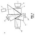
- FIG. 1 shows a simplified block diagram of a projector apparatus 10 that uses DLP spatial light modulators.
- a light source 12 provides polychromatic unpolarized light into a prism assembly 14, such as a Philips prism, for example.
- Prism assembly 14 splits the polychromatic light into red, green, and blue component wavelength bands and directs each band to the corresponding spatial light modulator 20r, 20g, or 20b.
- Prism assembly 14 then recombines the modulated light from each SLM 20r, 20g, and 20b and provides this unpolarized light to a projection lens 30 for projection onto a display screen or other suitable surface.
- DLP-based projectors demonstrate the capability to provide the necessary light throughput, contrast ratio, and color gamut for most projection applications from desktop to large cinema.
- resolution limitations with existing devices typically providing no more than 2148 x 1080 pixels.
- high component and system costs have limited the suitability of DLP designs for higher-quality digital cinema projection.
- the cost, size, weight, and complexity of the Philips or other suitable combining prisms are significant constraints.
- the need for a relatively fast projection lens with a long working distance, due to brightness requirements has had a negative impact on acceptability and usability of these devices.
- the second type of spatial light modulator used for digital projection is the LCD (Liquid Crystal Device).
- the LCD forms an image as an array of pixels by selectively modulating the polarization state of incident light for each corresponding pixel.
- LCDs appear to have advantages as spatial light modulators for high-quality digital cinema projection systems. These advantages include relatively large device size, favorable device yields and the ability to fabricate higher resolution devices, for example 4096 x 2160 resolution devices by Sony and JVC Corporations.
- electronic projection apparatus that utilize LCD spatial light modulators are those disclosed in U.S. Patent No. 5,808,795 (Shimomura et al. ); U.S. Patent No. 5,798,819 (Hattori et al. ); U.S. Patent No.
- LCOS Liquid Crystal On Silicon
- the second approach utilizes polarized light.
- One method assigned to InFocus Corporation, Wilsonville, OR, in US Patent No. 6,793,341 to Svardal et al. , utilizes each of two orthogonal polarization states delivered to two separate spatial light modulators. Polarized light from both modulators is projected simultaneously. The viewer wears polarized glasses with polarization transmission axes for left and right eyes orthogonally oriented with respect to each other. Although this arrangement offers efficient use of light, it can be a very expensive configuration, especially in projector designs where a spatial light modulator is required for each color band.
- a conventional digital projector is modified to modulate alternate polarization states that are rapidly switched from one to the other.
- a DLP projector has a polarizer placed in the output path of the light, such as at a position 16 indicated by a dashed line in Figure 1 .
- the polarizer is required as the DLP is not inherently designed to maintain the polarization of the input light as the window of the device package depolarizes due to stress induced birefringence.
- An achromatic polarization switcher similar to the type described in US application 200610291053 by Robinson et al. could be used at position 16 after the polarizer.
- a switcher of this type alternately rotates polarized light between two orthogonal polarization states, such as linear polarization states, to allow the presentation of two distinct images, one to each eye, while the user wears polarized glasses.
- Real-D systems historically have utilized left and right circularly polarized light, where the glasses are made of a combination 1 ⁇ 4 wave retarder plus a polarizer to change the circularly polarized light back to linearly polarized light before blocking one state. This apparently is less sensitive to head tilt and the achromatic polarization switcher is easier to fabricate.
- the glasses add expense over embodiments that simply use a polarizer. In either case, the display screen must substantially maintain the polarization state of the incident image-bearing light and is, therefore, typically silvered. Silvered screens are more costly and exhibit angular sensitivity for gain.
- etendue relates to the amount of light that can be handled by an optical system. Potentially, the larger the etendue, the brighter the image will be. Numerically, etendue is proportional to the product of two factors, namely the image area and the numerical aperture. In terms of the simplified optical system represented in Figure 2 having light source 12, optics 18, and a spatial light modulator 20, etendue is a factor of the area of the light source A I and its output angle ⁇ 1 and is equal to the area of the modulator A2 and its acceptance angle ⁇ 2. For increased brightness, it is desirable to provide as much light as possible from the area of the light source 12. As a general principle, the optical design is advantaged when the etendue at the light source is most closely matched to the etendue at the modulator.
- lens components in the optical system must be designed for large etendue.
- the source image area for the light that must be converged through system optics is the sum of the combined areas of the spatial light modulators in red, green, and blue light paths; notably, this is three times the area of the final multicolor image formed. That is, for the configuration disclosed in U.S. Patent No. 5,907,437 , optical components handle a sizable image area, therefore a high etendue, since red, green, and blue color paths are separate and must be optically converged. Moreover, although a configuration such as that disclosed in U.S. Patent No. 5,907,437 handles light from three times the area of the final multicolor image formed, this configuration does not afford any benefit of increased brightness, since each color path contains only one-third of the total light level.
- Efficiency improves when the etendue of the light source is well matched to the etendue of the spatial light modulator. Poorly matched etendue means that the optical system is either light starved, unable to provide sufficient light to the spatial light modulators, or inefficient, effectively discarding a substantial portion of the light that is generated for modulation.
- LCD-based systems have been compromised by the requirement for polarized light, reducing efficiency and increasing etendue, even where polarization recovery techniques are used.
- DLP device designs not requiring polarized light, have proven to be somewhat more efficient, but still require expensive, short-lived lamps and costly optical engines, making them too expensive to compete against conventional cinema projection equipment.
- digital projectors In order to compete with conventional high-end film-based projection systems and provide what has been termed electronic or digital cinema, digital projectors must be capable of achieving comparable cinema brightness levels to this earlier equipment. As some idea of scale, the typical theatre requires on the order of 10,000 lumens projected onto screen sizes on the order of 40 feet in diagonal. The range of screens requires anywhere from 5,000 lumens to upwards of 40,000 lumens. In addition to this demanding brightness requirement, these projectors must also deliver high resolution (2048 x 1080 pixels) and provide around 2000:1 1 contrast and a wide color gamut.
- Solid-state lasers promise improvements in etendue, longevity, and overall spectral and brightness stability but, until recently, have not been able to deliver visible light at sufficient levels and at costs acceptable for digital cinema.
- VCSEL Very Cavity Surface-Emitting Laser
- Examples of projection apparatus using laser arrays include the following:
- Kappel ⁇ 700 teaches the use of a monolithic array of coherent lasers for use as the light source in image projection, whereby the number of lasers is selected to match the power requirements of the lumen output of the projector. In a high lumen projector, however, this approach presents a number of difficulties. Manufacturing yields drop as the number of devices increases and heat problems can be significant with larger scale arrays. Coherence can also create problems for monolithic designs. Coherence of the laser sources typically causes artifacts such as optical interference and speckle. It is, therefore, preferable to use an array of lasers where coherence, spatial and temporal coherence is weak or negligible.
- spectral coherence is desirable from the standpoint of improved color gamut
- a small amount of spectral broadening is also desirable for reducing sensitivity to interference and speckle and also lessens the effects of color shift of a single spectral source.
- This shift could occur, for example, in a three-color projection system that has separate red, green and blue laser sources. If all lasers in the single color arrays are connected together and of a narrow wavelength, and a shift occurs in the operating wavelength, the white point and color of the entire projector may fall out of specification. On the other hand, where the array is averaged with small variations in the wavelengths, the sensitivity to single color shifts in the overall output is greatly reduced.
- reducing the spatial and temporal coherence at the source is preferred, as most means of reducing this incoherence beyond the source utilizes components such as diffusers that increase the effective extent of the source (etendue), cause additional light loss, and add expense to the system. Maintaining the small etendue of the lasers enables a simplification of the optical train for illumination, which is highly desirable.
- VECSEL Very Extended Cavity Surface-Emitting Laser
- NECSEL Novalux Extended Cavity Surface-Emitting Laser
- device yields Due largely to heat and packaging problems for critical components, the commercialized VECSEL array is extended in length, but limited in height; typically, a VECSEL array has only two rows of emitting sources. The use of more than two rows tends to dramatically increase yield and packaging difficulties. This practical limitation would make it difficult to provide a VECSEL illumination system for projection apparatus as described in the Glenn '145 disclosure, for example.
- Coupling of the laser sources to the projection system presents another difficulty that is not adequately addressed using conventional approaches.
- Novalux NESEL lasers approximately nine 2 row by 24 laser arrays are required for each color in order to approximate the 10,000 lumen requirement of most theatres. It is desirable to separate these sources, as well as the electronic delivery and connection and the associated heat from the main thermally sensitive optical system to allow optimal performance of the projection engine.
- Other laser sources are possible, such as conventional edge emitting laser diodes. However, these are more difficult to package in array form and traditionally have a shorter lifetime at higher brightness levels.
- the present invention provides a stereoscopic digital image projector system as defined in independent claim 1.
- This invention requires the use of a spectrally adjacent wavelength band.
- This term refers to substantially distinctive neighboring wavelength regions within a particular color spectrum.
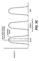
- typical digital display systems are often composed of three or more general color spectrums, defined as blue, green, and red. These may be composed of wavelength regions of between 30nm to 100 nm in spectral width. Within these color spectrums, smaller adjacent subsets can be defined. An example of this would be the blue color spectrum, which may be between 420nm and 460nm.
- Two spectrally adjacent bands may be comprised of spectrums of 420 to 430nm and 440 to 450nm. Both of these are within the general color spectrum band; however, they are also spectrally distinct.
- these spectrally adjacent colors would likely be narrower, as the laser spectrums are inherently narrow.
- Their spatial separation is defined by the requirements of any coatings that may be used to either combine the adjacent spectral bands or reject the adjacent spectral band. This small separation between the adjacent spectral bands enables the least variation in color space and the widest color gamut of the projection system. Therefore it is desirable to have these bands as close together as practical within the ability to fabricate a reasonable filter and also remain inside the general color spectrum.
- Embodiments of the present invention address the need for improved brightness in a stereoscopic viewing system using adjacent dual spectral sources and provide solutions that can also allow ease of removal and modular replacement of illumination assemblies.
- Embodiments of the present invention additionally provide features that reduce thermal effects that might otherwise cause thermally induced stress birefringence in optical components that are used with polarization-based projectors.
- Embodiments of the present invention take advantage of the inherent polarization of light that is emitted from a VECSEL laser array or other type of solid-state light array.
- One approach used to reduce thermal loading by embodiments of the present invention is to isolate the light sources from light modulation components using a waveguide structure.
- Light from multiple solid-state light source arrays is coupled into optical waveguides that deliver the light to the modulation device.
- the geometry of the light source-to-waveguide interface can be optimized so that the waveguide output is well matched to the aspect ratio of the spatial light modulator.
- the input aperture of a light guide 52 is shown in cross section.
- a solid-state light array 44 is shown as it would appear at the input aperture of light guide 52, if properly scaled.
- the aperture is underfilled, which may easily cause a poor etendue match at the spatial light modulator end of light guide 52.
- the aspect ratios of array 44 and light guide 52 are well matched by reshaping the input aperture of light guide 52 from its conventional circular form. Methods of combining multiple arrays 44 are described subsequently.
- an optical fiber can be utilized for light guide 52.
- a rectangular core optical fiber is used.
- rectangular core fiber from Liekki of Lohaja, Finland has been fabricated to better match source aspect ratios.
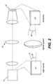
- FIG. 4 shows a basic arrangement for projection apparatus 10 that is used in a number of embodiments of the present invention.
- Three light modulation assemblies 40r, 40g, and 40b are shown, each modulating one of the primary Red, Green, or Blue (RGB) color bands from an illumination combiner 42.
- an optional lens 50 directs light into a light guide 52, such as an optical fiber.
- a lens 54 directs light through an integrator 51, such as a fly's eye integrator or integrating bar, for example, to a spatial light modulator 60, which may be a DLP, LCOS or other modulating component.
- a spatial light modulator 60 which may be a DLP, LCOS or other modulating component.
- LCOS LCOS
- Projection optics 70 indicated generally in a dashed outline in Figure 4 due to many possible embodiments, then directs the modulated light to a display surface 80.
- the overall arrangement shown in Figure 4 is then used for subsequent embodiments of the present invention, with various arrangements used for illumination combiner 42.
- Illumination combiner 42 alternately provides light of adjacent spectral bands, thus providing alternate left- and right-eye views in rapid succession.
- Figure 5 shows one approach for combining multiple arrays 44 and 44' to form a larger array.
- Figure 6 shows the configuration of Figure 5 in perspective view.
- one or more interspersed mirrors 46 may be used to place the optical axis of additional arrays 44' in line with array 44.
- heat and spacing requirements may limit how many arrays 44 can be stacked in this manner
- Figures 5 and 6 can be modified somewhat to allow the use of light having different, or shifted adjacent spectral content, as shown in Figures 7A and 7B and in the timing chart of Figure 8 .
- Figures 7A and 7B illustrate the illumination combiner 42
- the timing diagram of Figure 8 shows, within any one of light modulation assemblies 40r, 40g, and 40b, how light that is directed to the same spatial light modulator 60 ( Figure 4 ) can be rapidly alternated between two adjacent color spectrums to provide left- and right-eye images accordingly.
- There are two banks of lasers, for example purposes, solid-state laser arrays are shown, 44a and 44b. Lasers 44a and 44b provide light adjacent spectral bands.
- the duty cycle shown in Figure 8 is 50% illumination for each eye. Shorter duty cycles are possible, as long as the average power density on each eye is the same.
- the optimum duty cycle and frequency rate must be selected by the operational speed of the spatial light modulator, the operational speed of the laser device and the necessity to minimize discomfort by the viewer.
- a typical minimum acceptable frequency of 120hz refresh rate is desired, while higher frequencies are preferred. In 3D DLP based Digital Cinema applications, 144hz is often used.
- FIGS 16 and 17 show optical shutter 65 that is rotated in synchronization with the spatial light modulators by motor 66.
- Figure 17 illustrates that the optical shutter 65 includes a reflective portion 75 and a transmissive portion 76.
- portions 75 and 76 provide optical system illumination that alternates between the two adjacent color bands from 44a and 44b.
- the light from 44a and 44b are simultaneously reflected for 50% of the time corresponding to the image set on the spatial light modulator destined for the eye allowing the spectrum from illumination source 44a.
- Light from 44a is reflected off of optical shutter 65 and delivered to the spatial light modulator which is then projected to the screen for viewing by the user wearing color selective filter glasses allowing only light from adjacent spectrum 44a.
- Light from illumination source 44b is reflected into beam dump 67.
- optical shutter 65 transmits substantially all of illumination 44a and 44b. In this case, light from 44a ends at the beam dump 67, while light from 44b is delivered to the modulator which images content for the alternate eye. This light reaches the viewer's appropriate eye through the filter glasses designed to transmit only adjacent spectrum 44b.
- the prior art requires the use of a color selective coating to separate the appropriate adjacent spectrums. This must handle all three wavelength bands simultaneously.
- a simple mirror may be used for half of the optical shutter (reflective portion), while the other half may be a simple window (transmissive portion).
- two different wavelengths sensitive coatings designed with shifted edge filter designs may be used. As only one spectral band is required, this is substantially easier to fabricate without specialty coating types. In either case, proper anti reflection coatings may be desired on the substrates to prevent ghost reflections causing crosstalk light from entering the spatial light modulator from the inappropriate adjacent spectral band.
- the optical shutter may be removed and the dichroic beamsplitter may be reinserted. This can be automated by the content selection system.
- each of the lasers be adjacent in wavelength to minimize the color shift correction required for each eye to be minimal; conversely, it is also desirable to have enough of a spectral shift such that filters can be designed to sufficiently separate out the light from the left and right eyes, minimizing crosstalk.
- filters are typically fabricated by utilizing thin film based edge or bandpass filters. These filters have transition regions of wavelength ranging between a high transmission and blocking typically with smaller transitions (steeper) requiring more costly optical layers. This tradeoff between color space and transition space defines the specific desirable wavelength separation.
- NESCEL lasers typically have a variation of around .5nm between samples designed for the same spectral band.
- a minimum spectral separation would be 1 nm, provided an optical coating could be designed and fabricated with enough tolerance to have a transition region from full transmission to full blocking within 1nm. More typically, however, a minimum of 5nm would be required for such a coating. Therefore, the coating fabrication cost is often the limiting factor.
- arrays 44a are energized, as shown in Figure 7A .
- This light reflects from a dichroic beamsplitter 62.
- arrays 44b are energized, as shown in Figure 7B .
- This light is transmitted through dichroic beamsplitter 62.
- the light from both adjacent lasers 44a and 44b may be used together to provide a brighter imager, or used at half power to balance the lifetime each laser source.
- the overall width of the selected primary bands should be well below the width of conventional Xenon light sources, where typical bands may be as high as 100nm. In the case where lasers are used, a total band including both adjacent spectrums might encompass only 20nm or less, providing sufficient margin for very simple optical coating to be made, as well as a substantially larger color gamut compared with traditional illumination.
- Figures 9A and 9B show side and orthogonal views, respectively, of an embodiment of illumination combiner 42 that combines laser light from four solid-state light arrays 44, concentrated within a smaller area.
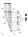
- a light-redirecting prism 30 has an incident face 32 that accepts light emitted from array 44 in an emission direction D1. Light is redirected to an output direction D2 that lies along the direction of the optical axis and is substantially orthogonal to emission direction D1.
- Light redirecting prism 30 has a redirection surface 36 that has light-redirecting facets 38. Light-redirecting facets 38 are at an oblique angle relative to emission direction D1 and provide Total Internal Reflection (TIR) to light emitted from lasers 26.
- TIR Total Internal Reflection
- light arrays 44 have multiple lasers 26 that extend in a length direction L.
- Light-redirecting facets 38 and other facets on redirection surface 36 also extend in direction L.
- the cross-sectional side view of Figure 10 shows an alternate embodiment in which light-directing facets 38 of light redirecting prism 30 are scaled to redirect light from multiple rows of lasers on light arrays 44 at a time.
- Incident face 32 may not be normal with respect to emission direction D1, allowing some offset to the arrangement of light arrays 44 and requiring that the index of refraction n of light redirecting prism 30 be taken into account.
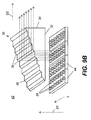
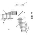
- FIG. 11 shows how multiple light redirecting prisms 30 can be utilized to provide increased brightness in an embodiment that uses adjacent color bands.
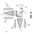
- FIG. 12 shows another embodiment of light-redirecting prism 30 in illumination combiner 42 that provides an even more compact arrangement of illumination than the embodiment shown in Figures 9A-10 for using solid-state arrays.
- light redirecting prism 30 has two redirection surfaces 36, accepting light from arrays 44 that are facing each other, with opposing emission directions D1 and D1'.
- Each redirection surface 36 has two types of facets: a light-redirecting facet 38 and an incidence facet 28 that can be normal to the incident light from the corresponding array 44 or at some other angle oblique to normal.
- This retro-reflection can be useful as a means of creating a subtle external cavity that may induce mode instability in laser. While such mode hopping may be considered noise under typical applications, this noise can add value in projection by further reducing the laser coherence (and inter-laser coherence) thereby reducing visual speckle at the image plane.
- laser modules are interleaved with light from differing modules neighboring each other, providing a source of further spatial mixing when the light is optically integrated further in the optical system. This again helps to reduce possible speckle and increase system uniformity.
- the schematic block diagram of Figure 14 shows an embodiment of projector apparatus 10 that uses light-redirecting prisms 30 in each color channel following the basic arrangement described with respect to Figure 13 .
- Each light modulation assembly 40r, 40g, and 40b has a pair of light redirecting prisms 30 configured with dichroic beam 62.
- adjacent spectral band light from one or the other light-redirecting prism 30 is directed through light guide 52 to lens 50 and integrator 51 through dichroic beamsplitter 62.
- Spatial light modulator 60 is a digital micromirror, LCOS, other device that modulates light.
- Dichroic combiner 82 has an arrangement of dichroic surfaces 84 that selectively reflect or transmit light according to wavelength, combining the modulated light from each light modulation assembly 40r, 40g, and 40b onto a single optical path through projection optics 70.
- the light modulation assemblies 40r, 40g, and 40b consist of the dual adjacent spectral bands; the dichroic surfaces 84 are designed to treat both of these adjacent bands similarly.
- FIG. 15 shows an alternate embodiment of projector apparatus 10 in an embodiment similar to that of Figure 14 , but without light guides 52.
- This embodiment can be advantaged because light guides 52 can tend to degrade polarization of the transmitted light.
- lenslet arrays would offer advantages for uniformizing the illumination, since polarization states are maintained.
- Light directing prism 30 can be made from many highly transmissive materials. For low power applications, plastics may be chosen, with molding processes be used that induce very little stress to the part. Similarly, it is desirable to have the materials chosen such that they induce minimal stress or thermally induced birefringence. Plastics such as acrylic or Zeonex from Zeon Chemicals would be examples of such materials. This is particularly important in the case where light-directing prism 30 is used in a polarization based optical system.
- plastics may be impractical for use with light directing prism 30, since the heat buildup from even small level of optical absorption could ultimately damage the material and degrade transmission.
- glass would be preferred. Again stress birefringence could be a problem for polarization-based projectors. In this case, glass with low stress coefficient of birefringence, such as SF57, could be used.
- Another option would be to use a very low absorption optical glass, such as fused silica, to prevent heat up of the material and therefore keep the birefringence from occurring.
- a very low absorption optical glass such as fused silica
- fused silica may not be conducive to creating a molded glass component, thus requiring conventional polishing and or assembly of multiple pieces to make up the completed prism.
- a slow mold process would be preferred, and annealing is desirable to reduce any inherent stress.
- a clean up polarizer may be desired or necessary to remove any rotated polarization states that might develop from any residual birefringence. This is primarily a trade off of efficiency, component cost and required polarization purity.
- Embodiments of the present invention can be useful for shaping the aspect ratio of the light source so that it suits the aspect ratio of the spatial light modulator that is used.
- Embodiments of the present invention can be used with light guides 52 of different dimensions, allowing the light guide to be not only flexible, but also shaped with substantially the same aspect ratio to that of the modulator. For digital cinema this ratio would be approximately 1.9:1.
- An alternate embodiment could use a square core fiber.
- a round core optical waveguide, such as common multimode optical fiber can be utilized.
Landscapes
- Physics & Mathematics (AREA)
- General Physics & Mathematics (AREA)
- Engineering & Computer Science (AREA)
- Multimedia (AREA)
- Signal Processing (AREA)
- Optics & Photonics (AREA)
- Spectroscopy & Molecular Physics (AREA)
- Projection Apparatus (AREA)
- Transforming Electric Information Into Light Information (AREA)
- Testing, Inspecting, Measuring Of Stereoscopic Televisions And Televisions (AREA)
Applications Claiming Priority (2)
| Application Number | Priority Date | Filing Date | Title |
|---|---|---|---|
| US11/956,666 US20090153752A1 (en) | 2007-12-14 | 2007-12-14 | Projector using independent multiple wavelength light sources |
| PCT/US2008/013610 WO2009078941A1 (en) | 2007-12-14 | 2008-12-11 | Projector using independent multiple wavelength light sources |
Publications (2)
| Publication Number | Publication Date |
|---|---|
| EP2220533A1 EP2220533A1 (en) | 2010-08-25 |
| EP2220533B1 true EP2220533B1 (en) | 2011-11-23 |
Family
ID=40429967
Family Applications (1)
| Application Number | Title | Priority Date | Filing Date |
|---|---|---|---|
| EP08861927A Active EP2220533B1 (en) | 2007-12-14 | 2008-12-11 | Projector using independent multiple wavelength light sources |
Country Status (8)
| Country | Link |
|---|---|
| US (1) | US20090153752A1 (enExample) |
| EP (1) | EP2220533B1 (enExample) |
| JP (1) | JP5416129B2 (enExample) |
| CN (1) | CN101889233B (enExample) |
| AT (1) | ATE534931T1 (enExample) |
| CA (1) | CA2703860A1 (enExample) |
| TW (1) | TWI439733B (enExample) |
| WO (1) | WO2009078941A1 (enExample) |
Families Citing this family (92)
| Publication number | Priority date | Publication date | Assignee | Title |
|---|---|---|---|---|
| US7871165B2 (en) * | 2007-11-30 | 2011-01-18 | Eastman Kodak Company | Stereo projection apparatus using polarized solid state light sources |
| US7891816B2 (en) * | 2008-02-25 | 2011-02-22 | Eastman Kodak Company | Stereo projection using polarized solid state light sources |
| US20090309127A1 (en) * | 2008-06-13 | 2009-12-17 | Soraa, Inc. | Selective area epitaxy growth method and structure |
| US8847249B2 (en) | 2008-06-16 | 2014-09-30 | Soraa, Inc. | Solid-state optical device having enhanced indium content in active regions |
| US7926951B2 (en) * | 2008-07-11 | 2011-04-19 | Eastman Kodak Company | Laser illuminated micro-mirror projector |
| US8767787B1 (en) | 2008-07-14 | 2014-07-01 | Soraa Laser Diode, Inc. | Integrated laser diodes with quality facets on GaN substrates |
| US8143148B1 (en) | 2008-07-14 | 2012-03-27 | Soraa, Inc. | Self-aligned multi-dielectric-layer lift off process for laser diode stripes |
| US8805134B1 (en) | 2012-02-17 | 2014-08-12 | Soraa Laser Diode, Inc. | Methods and apparatus for photonic integration in non-polar and semi-polar oriented wave-guided optical devices |
| JP2011530194A (ja) | 2008-08-04 | 2011-12-15 | ソラア インコーポレーテッド | 物質および蛍光体を含んだ非分極性あるいは半極性のガリウムを用いた白色灯デバイス |
| US8284810B1 (en) | 2008-08-04 | 2012-10-09 | Soraa, Inc. | Solid state laser device using a selected crystal orientation in non-polar or semi-polar GaN containing materials and methods |
| US8837545B2 (en) | 2009-04-13 | 2014-09-16 | Soraa Laser Diode, Inc. | Optical device structure using GaN substrates and growth structures for laser applications |
| US8634442B1 (en) | 2009-04-13 | 2014-01-21 | Soraa Laser Diode, Inc. | Optical device structure using GaN substrates for laser applications |
| US9531164B2 (en) * | 2009-04-13 | 2016-12-27 | Soraa Laser Diode, Inc. | Optical device structure using GaN substrates for laser applications |
| US10108079B2 (en) * | 2009-05-29 | 2018-10-23 | Soraa Laser Diode, Inc. | Laser light source for a vehicle |
| US9829780B2 (en) * | 2009-05-29 | 2017-11-28 | Soraa Laser Diode, Inc. | Laser light source for a vehicle |
| US9800017B1 (en) | 2009-05-29 | 2017-10-24 | Soraa Laser Diode, Inc. | Laser device and method for a vehicle |
| US8427590B2 (en) * | 2009-05-29 | 2013-04-23 | Soraa, Inc. | Laser based display method and system |
| US9250044B1 (en) | 2009-05-29 | 2016-02-02 | Soraa Laser Diode, Inc. | Gallium and nitrogen containing laser diode dazzling devices and methods of use |
| US8509275B1 (en) | 2009-05-29 | 2013-08-13 | Soraa, Inc. | Gallium nitride based laser dazzling device and method |
| US8247887B1 (en) | 2009-05-29 | 2012-08-21 | Soraa, Inc. | Method and surface morphology of non-polar gallium nitride containing substrates |
| US8851684B2 (en) * | 2009-06-18 | 2014-10-07 | Nec Display Solutions, Ltd. | Optical unit including an integrator optical system, and projection display device including the optical unit |
| US20100328611A1 (en) * | 2009-06-25 | 2010-12-30 | Silverstein Barry D | Leakage light intensity sensing in light projector |
| US8237777B2 (en) * | 2009-06-25 | 2012-08-07 | Eastman Kodak Company | Stereoscopic image intensity balancing in light projector |
| US8142021B2 (en) * | 2009-06-25 | 2012-03-27 | Eastman Kodak Company | Dump path light intensity sensing in light projector |
| US8162483B2 (en) * | 2009-06-25 | 2012-04-24 | Eastman Kodak Company | Hierarchical light intensity control in light projector |
| US8220938B2 (en) * | 2009-06-25 | 2012-07-17 | Eastman Kodak Company | Image path light intensity sensing during a blanking period between a left-eye light beam and a right-eye light beam in a stereoscopic light projector |
| US8066382B2 (en) * | 2009-07-14 | 2011-11-29 | Eastman Kodak Company | Stereoscopic projector with rotating segmented disk |
| JP2011043703A (ja) * | 2009-08-21 | 2011-03-03 | Victor Co Of Japan Ltd | 照明装置及びこの照明装置を用いた投射型映像表示装置 |
| US8750342B1 (en) | 2011-09-09 | 2014-06-10 | Soraa Laser Diode, Inc. | Laser diodes with scribe structures |
| US8355418B2 (en) | 2009-09-17 | 2013-01-15 | Soraa, Inc. | Growth structures and method for forming laser diodes on {20-21} or off cut gallium and nitrogen containing substrates |
| US20110102563A1 (en) * | 2009-11-03 | 2011-05-05 | Johnson Jr Robert L | Multi-spectral stereographic display system |
| US20110102562A1 (en) * | 2009-11-03 | 2011-05-05 | PV Omega, LLC | Multi-spectral stereographic display system with additive and subtractive techniques |
| US8320621B2 (en) | 2009-12-21 | 2012-11-27 | Microsoft Corporation | Depth projector system with integrated VCSEL array |
| US8444272B2 (en) * | 2010-01-25 | 2013-05-21 | Corning Incorporated | Multi-projector system using multiplexed illumination |
| US10147850B1 (en) | 2010-02-03 | 2018-12-04 | Soraa, Inc. | System and method for providing color light sources in proximity to predetermined wavelength conversion structures |
| US8905588B2 (en) | 2010-02-03 | 2014-12-09 | Sorra, Inc. | System and method for providing color light sources in proximity to predetermined wavelength conversion structures |
| US8451876B1 (en) | 2010-05-17 | 2013-05-28 | Soraa, Inc. | Method and system for providing bidirectional light sources with broad spectrum |
| US8670029B2 (en) | 2010-06-16 | 2014-03-11 | Microsoft Corporation | Depth camera illuminator with superluminescent light-emitting diode |
| US8816319B1 (en) | 2010-11-05 | 2014-08-26 | Soraa Laser Diode, Inc. | Method of strain engineering and related optical device using a gallium and nitrogen containing active region |
| US9048170B2 (en) | 2010-11-09 | 2015-06-02 | Soraa Laser Diode, Inc. | Method of fabricating optical devices using laser treatment |
| US9025635B2 (en) | 2011-01-24 | 2015-05-05 | Soraa Laser Diode, Inc. | Laser package having multiple emitters configured on a support member |
| US9595813B2 (en) | 2011-01-24 | 2017-03-14 | Soraa Laser Diode, Inc. | Laser package having multiple emitters configured on a substrate member |
| US9093820B1 (en) | 2011-01-25 | 2015-07-28 | Soraa Laser Diode, Inc. | Method and structure for laser devices using optical blocking regions |
| US9236530B2 (en) | 2011-04-01 | 2016-01-12 | Soraa, Inc. | Miscut bulk substrates |
| US9287684B2 (en) | 2011-04-04 | 2016-03-15 | Soraa Laser Diode, Inc. | Laser package having multiple emitters with color wheel |
| US9325976B2 (en) | 2011-05-02 | 2016-04-26 | Dolby Laboratories Licensing Corporation | Displays, including HDR and 3D, using bandpass filters and other techniques |
| DE102012010210A1 (de) | 2011-05-17 | 2012-11-22 | Lumatec Gesellschaft für medizinisch-technische Geräte mbH | Beleuchtungseinrichtung, sowie Beleuchtungsvorrichtung, optischer Projektor und Scheinwerfer jeweils mit zumindest einer derartigen Beleuchtungseinrichtung |
| US9646827B1 (en) | 2011-08-23 | 2017-05-09 | Soraa, Inc. | Method for smoothing surface of a substrate containing gallium and nitrogen |
| US8651663B2 (en) | 2011-10-03 | 2014-02-18 | Eastman Kodak Company | Stereoscopic projector using scrolling color bands |
| US8746888B2 (en) | 2011-10-03 | 2014-06-10 | Eastman Kodak Company | Stereoscopic projector using spectrally-adjacent color bands |
| US8971370B1 (en) | 2011-10-13 | 2015-03-03 | Soraa Laser Diode, Inc. | Laser devices using a semipolar plane |
| CN102402005B (zh) * | 2011-12-06 | 2015-11-25 | 北京理工大学 | 自由曲面双焦面单目立体头盔显示器装置 |
| CN103207509B (zh) * | 2012-01-12 | 2015-06-24 | 三菱电机株式会社 | 光源装置和投影式显示装置 |
| US20130182321A1 (en) | 2012-01-17 | 2013-07-18 | Barry David Silverstein | Filter glasses for spectral stereoscopic projection system |
| US10768449B2 (en) | 2012-01-17 | 2020-09-08 | Imax Theatres International Limited | Stereoscopic glasses using tilted filters |
| US8864314B2 (en) | 2012-01-17 | 2014-10-21 | Eastman Kodak Company | Stereoscopic projection system using tunable light emitters |
| US8947424B2 (en) | 2012-01-17 | 2015-02-03 | Eastman Kodak Company | Spectral stereoscopic projection system |
| US9335541B2 (en) | 2012-01-17 | 2016-05-10 | Imax Theatres International Limited | Stereoscopic glasses using dichroic and absorptive layers |
| US9020003B1 (en) | 2012-03-14 | 2015-04-28 | Soraa Laser Diode, Inc. | Group III-nitride laser diode grown on a semi-polar orientation of gallium and nitrogen containing substrates |
| JP2013197033A (ja) * | 2012-03-22 | 2013-09-30 | Harison Toshiba Lighting Corp | 固体照明装置 |
| US10559939B1 (en) | 2012-04-05 | 2020-02-11 | Soraa Laser Diode, Inc. | Facet on a gallium and nitrogen containing laser diode |
| US9343871B1 (en) | 2012-04-05 | 2016-05-17 | Soraa Laser Diode, Inc. | Facet on a gallium and nitrogen containing laser diode |
| US9800016B1 (en) | 2012-04-05 | 2017-10-24 | Soraa Laser Diode, Inc. | Facet on a gallium and nitrogen containing laser diode |
| WO2013155319A1 (en) | 2012-04-13 | 2013-10-17 | Red. Com, Inc. | Video projector system |
| US8998447B2 (en) | 2012-09-26 | 2015-04-07 | Projectdesign As | Illumination devices using array of reflectors |
| JP6021200B2 (ja) * | 2012-12-27 | 2016-11-09 | Necディスプレイソリューションズ株式会社 | プロジェクターおよびその制御方法 |
| KR102135345B1 (ko) * | 2013-01-22 | 2020-07-17 | 엘지전자 주식회사 | 영상투사장치 |
| WO2014115493A1 (ja) * | 2013-01-23 | 2014-07-31 | 三菱電機株式会社 | 投写型表示装置 |
| US10237523B2 (en) * | 2013-05-07 | 2019-03-19 | Dolby Laboratories Licensing Corporation | Digital point spread function (DPSF) and dual modulation projection (including lasers) using DPSF |
| JP6008810B2 (ja) * | 2013-09-05 | 2016-10-19 | ウシオ電機株式会社 | レーザ光源装置 |
| US9329461B2 (en) | 2013-10-28 | 2016-05-03 | Dell Products, Lp | Hybrid light engine for projector |
| TWI526771B (zh) | 2014-07-04 | 2016-03-21 | 台達電子工業股份有限公司 | 光源系統 |
| US9246311B1 (en) | 2014-11-06 | 2016-01-26 | Soraa Laser Diode, Inc. | Method of manufacture for an ultraviolet laser diode |
| CN112946974B (zh) | 2014-12-31 | 2022-11-08 | 杜比实验室特许公司 | 用于图像投影仪的高对比度分立输入棱镜 |
| JP6508466B2 (ja) * | 2015-05-29 | 2019-05-08 | セイコーエプソン株式会社 | 光源装置およびプロジェクター |
| US10481092B2 (en) * | 2015-07-21 | 2019-11-19 | Queen's University At Kingston | Multiplexed excitation emission matrix spectroscopy |
| US11437774B2 (en) | 2015-08-19 | 2022-09-06 | Kyocera Sld Laser, Inc. | High-luminous flux laser-based white light source |
| WO2017038203A1 (ja) | 2015-08-28 | 2017-03-09 | 富士フイルム株式会社 | 距離画像取得装置付きプロジェクタ装置及びプロジェクションマッピング方法 |
| US9787963B2 (en) | 2015-10-08 | 2017-10-10 | Soraa Laser Diode, Inc. | Laser lighting having selective resolution |
| CN107463057A (zh) * | 2016-06-02 | 2017-12-12 | 中强光电股份有限公司 | 投影系统与照明系统 |
| ES2831431T3 (es) | 2016-09-30 | 2021-06-08 | Dolby Laboratories Licensing Corp | Combinación de haces para proyección resaltada |
| CN115464159B (zh) | 2017-05-11 | 2024-07-16 | 速尔特技术有限公司 | 用于增材制造的图案化光的开关站射束路由 |
| JP7208162B2 (ja) | 2017-05-11 | 2023-01-18 | シューラット テクノロジーズ,インク. | 付加製造最適化のためのパターン化された光の固体ルーティング |
| US10771155B2 (en) | 2017-09-28 | 2020-09-08 | Soraa Laser Diode, Inc. | Intelligent visible light with a gallium and nitrogen containing laser source |
| US10222474B1 (en) | 2017-12-13 | 2019-03-05 | Soraa Laser Diode, Inc. | Lidar systems including a gallium and nitrogen containing laser light source |
| US10551728B1 (en) | 2018-04-10 | 2020-02-04 | Soraa Laser Diode, Inc. | Structured phosphors for dynamic lighting |
| US11421843B2 (en) | 2018-12-21 | 2022-08-23 | Kyocera Sld Laser, Inc. | Fiber-delivered laser-induced dynamic light system |
| US11239637B2 (en) | 2018-12-21 | 2022-02-01 | Kyocera Sld Laser, Inc. | Fiber delivered laser induced white light system |
| US11884202B2 (en) | 2019-01-18 | 2024-01-30 | Kyocera Sld Laser, Inc. | Laser-based fiber-coupled white light system |
| US12152742B2 (en) | 2019-01-18 | 2024-11-26 | Kyocera Sld Laser, Inc. | Laser-based light guide-coupled wide-spectrum light system |
| US12000552B2 (en) | 2019-01-18 | 2024-06-04 | Kyocera Sld Laser, Inc. | Laser-based fiber-coupled white light system for a vehicle |
| US12191626B1 (en) | 2020-07-31 | 2025-01-07 | Kyocera Sld Laser, Inc. | Vertically emitting laser devices and chip-scale-package laser devices and laser-based, white light emitting devices |
Family Cites Families (49)
| Publication number | Priority date | Publication date | Assignee | Title |
|---|---|---|---|---|
| US4441791A (en) * | 1980-09-02 | 1984-04-10 | Texas Instruments Incorporated | Deformable mirror light modulator |
| JPH01116521A (ja) * | 1987-10-29 | 1989-05-09 | Furotsugusu:Kk | 色付き立体視方法 |
| JPH0278393A (ja) * | 1988-09-14 | 1990-03-19 | Hitachi Ltd | 立体カラー画像表示装置 |
| US5083857A (en) * | 1990-06-29 | 1992-01-28 | Texas Instruments Incorporated | Multi-level deformable mirror device |
| US5704700A (en) * | 1994-07-25 | 1998-01-06 | Proxima Corporation | Laser illuminated image projection system and method of using same |
| US5537476A (en) * | 1994-11-21 | 1996-07-16 | International Business Machines Corporation | Secure viewing of display units by image superposition and wavelength separation |
| EP0722253A3 (en) * | 1995-01-10 | 1996-10-30 | Ibm | Arrangements for projection display devices using optical valves in reflection |
| US5808795A (en) * | 1995-03-06 | 1998-09-15 | Nikon Corporation | Projection type display apparatus |
| US6062694A (en) * | 1995-03-06 | 2000-05-16 | Nikon Corporation | Projection type display apparatus |
| US5719695A (en) * | 1995-03-31 | 1998-02-17 | Texas Instruments Incorporated | Spatial light modulator with superstructure light shield |
| US5535047A (en) * | 1995-04-18 | 1996-07-09 | Texas Instruments Incorporated | Active yoke hidden hinge digital micromirror device |
| JPH09159988A (ja) * | 1995-12-12 | 1997-06-20 | Nikon Corp | 投射型表示装置 |
| JP3738505B2 (ja) * | 1996-05-10 | 2006-01-25 | 株式会社ニコン | 投射型表示装置 |
| JP3557317B2 (ja) * | 1996-09-02 | 2004-08-25 | テキサス インスツルメンツ インコーポレイテツド | プロジエクタ装置及び色分離合成装置 |
| US5914818A (en) * | 1996-11-29 | 1999-06-22 | Texas Instruments Incorporated | Offset projection lens for use with reflective spatial light modulators |
| US6008951A (en) * | 1996-12-31 | 1999-12-28 | Texas Instruments Incorporated | Offset projection zoom lens with fixed rear group for reflective spatial light modulators |
| WO1998049837A1 (de) * | 1997-04-30 | 1998-11-05 | Ldt Gmbh & Co. Laser-Display-Technologie Kg | Verfahren und system zur projektion von bildern auf einen schirm mit hilfe eines lichtbündels |
| US6215464B1 (en) * | 1997-06-10 | 2001-04-10 | Jorgen Korsgaard Jensen | Stereoscopic intersecting beam phosphorous display system |
| US5907437A (en) * | 1997-07-10 | 1999-05-25 | Hughes-Jvc Technology Corporation | Converging optics for a single light valve full-color projector |
| US6240116B1 (en) * | 1997-08-14 | 2001-05-29 | Sdl, Inc. | Laser diode array assemblies with optimized brightness conservation |
| US5930050A (en) * | 1997-10-21 | 1999-07-27 | Texas Instruments Incorporated | Anamorphic lens for providing wide-screen images generated by a spatial light modulator |
| US6010121A (en) * | 1999-04-21 | 2000-01-04 | Lee; Chi Ping | Work piece clamping device of workbench |
| DE19924167B4 (de) * | 1999-05-26 | 2006-05-24 | Daimlerchrysler Ag | Vorrichtung zur Wiedergabe von Farbbildern |
| DE10005335C2 (de) * | 2000-02-08 | 2002-06-27 | Daimler Chrysler Ag | Verfahren und Vorrichtung zur mehrdimensionalen Darstellung eines Objekts |
| US6501773B1 (en) * | 2000-06-19 | 2002-12-31 | Versatile Optical Networks, Inc. | Stabilization of a laser array module |
| US7102700B1 (en) * | 2000-09-02 | 2006-09-05 | Magic Lantern Llc | Laser projection system |
| US6547396B1 (en) * | 2001-12-27 | 2003-04-15 | Infocus Corporation | Stereographic projection system |
| JP2003186112A (ja) * | 2001-12-19 | 2003-07-03 | Olympus Optical Co Ltd | 画像投影表示装置 |
| US7520624B2 (en) * | 2001-12-21 | 2009-04-21 | Bose Corporation | Light enhancing |
| JP4503910B2 (ja) * | 2002-03-08 | 2010-07-14 | オリンパス株式会社 | 画像表示方法、画像表示装置及び画像印刷装置 |
| US6802613B2 (en) * | 2002-10-16 | 2004-10-12 | Eastman Kodak Company | Broad gamut color display apparatus using an electromechanical grating device |
| WO2004080053A2 (en) * | 2003-02-28 | 2004-09-16 | Florida Atlantic University | Displays using solid state light sources |
| US6950454B2 (en) * | 2003-03-24 | 2005-09-27 | Eastman Kodak Company | Electronic imaging system using organic laser array illuminating an area light valve |
| JP2004333561A (ja) * | 2003-04-30 | 2004-11-25 | Nippon Hoso Kyokai <Nhk> | 立体画像表示装置 |
| US7832869B2 (en) * | 2003-10-21 | 2010-11-16 | Barco N.V. | Method and device for performing stereoscopic image display based on color selective filters |
| US8587849B2 (en) * | 2004-04-05 | 2013-11-19 | Hewlett-Packard Development Company, L.P. | Imaging systems, imaging device analysis systems, imaging device analysis methods, and light beam emission methods |
| KR20070046831A (ko) * | 2004-07-30 | 2007-05-03 | 노바룩스 인코포레이티드 | 투사 디스플레이 장치, 시스템 및 방법 |
| JP2006337609A (ja) * | 2005-05-31 | 2006-12-14 | Sanyo Electric Co Ltd | 照明装置、投写型映像表示装置 |
| US20060280209A1 (en) * | 2005-02-11 | 2006-12-14 | Hans-Georg Treusch | Beam combining methods and devices with high output intensity |
| JP2006349731A (ja) * | 2005-06-13 | 2006-12-28 | Olympus Corp | 画像投影装置 |
| US20070024959A1 (en) * | 2005-07-26 | 2007-02-01 | Infocus Corporation | Laser combiner |
| US20080077200A1 (en) * | 2006-09-21 | 2008-03-27 | Aculight Corporation | Apparatus and method for stimulation of nerves and automated control of surgical instruments |
| WO2007056541A2 (en) * | 2005-11-08 | 2007-05-18 | Young Garrett J | Apparatus and method for generating light from multi - primary colors |
| US7528906B2 (en) * | 2006-01-23 | 2009-05-05 | Real D | Achromatic polarization switches |
| US8730306B2 (en) * | 2006-04-25 | 2014-05-20 | Corporation For Laser Optics Research | 3-D projection full color multimedia display |
| EP2044479A4 (en) * | 2006-07-02 | 2010-08-25 | Simon Andrew Boothroyd | IMAGE COMBINING DEVICE AND PROJECTION SCREEN APPARATUS WITH INCORPORATED IMAGE COMBINATION DEVICES |
| US8427394B2 (en) * | 2006-11-30 | 2013-04-23 | Reald Inc. | Shutter glass drive scheme for sequential-color displays |
| US8388138B1 (en) * | 2007-03-11 | 2013-03-05 | Simon Boothroyd | Projection display systems |
| US8107035B2 (en) * | 2007-04-19 | 2012-01-31 | Necsel Intellectual Property | Laser backlighting for displays |
-
2007
- 2007-12-14 US US11/956,666 patent/US20090153752A1/en not_active Abandoned
-
2008
- 2008-12-11 CA CA2703860A patent/CA2703860A1/en not_active Abandoned
- 2008-12-11 EP EP08861927A patent/EP2220533B1/en active Active
- 2008-12-11 CN CN2008801192853A patent/CN101889233B/zh not_active Expired - Fee Related
- 2008-12-11 WO PCT/US2008/013610 patent/WO2009078941A1/en not_active Ceased
- 2008-12-11 AT AT08861927T patent/ATE534931T1/de active
- 2008-12-11 JP JP2010537960A patent/JP5416129B2/ja not_active Expired - Fee Related
- 2008-12-12 TW TW097148602A patent/TWI439733B/zh active
Also Published As
| Publication number | Publication date |
|---|---|
| CA2703860A1 (en) | 2009-06-25 |
| JP2011510333A (ja) | 2011-03-31 |
| CN101889233B (zh) | 2012-07-04 |
| JP5416129B2 (ja) | 2014-02-12 |
| US20090153752A1 (en) | 2009-06-18 |
| ATE534931T1 (de) | 2011-12-15 |
| WO2009078941A1 (en) | 2009-06-25 |
| EP2220533A1 (en) | 2010-08-25 |
| TWI439733B (zh) | 2014-06-01 |
| TW200931067A (en) | 2009-07-16 |
| CN101889233A (zh) | 2010-11-17 |
Similar Documents
| Publication | Publication Date | Title |
|---|---|---|
| EP2220533B1 (en) | Projector using independent multiple wavelength light sources | |
| EP2215848B1 (en) | Stereo projection apparatus | |
| EP2248346B1 (en) | Stereo projection using polarized solid state light sources | |
| EP2454633B1 (en) | Stereoscopic projector with rotating segmented disk | |
| EP2274918B1 (en) | Laser projection using spatial and temporal mixing | |
| EP2423744B1 (en) | Laser illuminated micro-mirror projector | |
| US8220931B2 (en) | Etendue reduced stereo projection using segmented disk | |
| WO2009061357A1 (en) | Projection apparatus using solid-state light source array | |
| US20110261174A1 (en) | Stereoscopic digital projection apparatus using polarized light |
Legal Events
| Date | Code | Title | Description |
|---|---|---|---|
| PUAI | Public reference made under article 153(3) epc to a published international application that has entered the european phase |
Free format text: ORIGINAL CODE: 0009012 |
|
| 17P | Request for examination filed |
Effective date: 20100616 |
|
| AK | Designated contracting states |
Kind code of ref document: A1 Designated state(s): AT BE BG CH CY CZ DE DK EE ES FI FR GB GR HR HU IE IS IT LI LT LU LV MC MT NL NO PL PT RO SE SI SK TR |
|
| AX | Request for extension of the european patent |
Extension state: AL BA MK RS |
|
| DAX | Request for extension of the european patent (deleted) | ||
| GRAP | Despatch of communication of intention to grant a patent |
Free format text: ORIGINAL CODE: EPIDOSNIGR1 |
|
| GRAS | Grant fee paid |
Free format text: ORIGINAL CODE: EPIDOSNIGR3 |
|
| GRAA | (expected) grant |
Free format text: ORIGINAL CODE: 0009210 |
|
| AK | Designated contracting states |
Kind code of ref document: B1 Designated state(s): AT BE BG CH CY CZ DE DK EE ES FI FR GB GR HR HU IE IS IT LI LT LU LV MC MT NL NO PL PT RO SE SI SK TR |
|
| REG | Reference to a national code |
Ref country code: GB Ref legal event code: FG4D |
|
| REG | Reference to a national code |
Ref country code: CH Ref legal event code: EP |
|
| REG | Reference to a national code |
Ref country code: IE Ref legal event code: FG4D |
|
| REG | Reference to a national code |
Ref country code: DE Ref legal event code: R096 Ref document number: 602008011610 Country of ref document: DE Effective date: 20120119 |
|
| REG | Reference to a national code |
Ref country code: NL Ref legal event code: T3 |
|
| LTIE | Lt: invalidation of european patent or patent extension |
Effective date: 20111123 |
|
| PG25 | Lapsed in a contracting state [announced via postgrant information from national office to epo] |
Ref country code: NO Free format text: LAPSE BECAUSE OF FAILURE TO SUBMIT A TRANSLATION OF THE DESCRIPTION OR TO PAY THE FEE WITHIN THE PRESCRIBED TIME-LIMIT Effective date: 20120223 Ref country code: IS Free format text: LAPSE BECAUSE OF FAILURE TO SUBMIT A TRANSLATION OF THE DESCRIPTION OR TO PAY THE FEE WITHIN THE PRESCRIBED TIME-LIMIT Effective date: 20120323 Ref country code: LT Free format text: LAPSE BECAUSE OF FAILURE TO SUBMIT A TRANSLATION OF THE DESCRIPTION OR TO PAY THE FEE WITHIN THE PRESCRIBED TIME-LIMIT Effective date: 20111123 |
|
| PG25 | Lapsed in a contracting state [announced via postgrant information from national office to epo] |
Ref country code: SI Free format text: LAPSE BECAUSE OF FAILURE TO SUBMIT A TRANSLATION OF THE DESCRIPTION OR TO PAY THE FEE WITHIN THE PRESCRIBED TIME-LIMIT Effective date: 20111123 Ref country code: GR Free format text: LAPSE BECAUSE OF FAILURE TO SUBMIT A TRANSLATION OF THE DESCRIPTION OR TO PAY THE FEE WITHIN THE PRESCRIBED TIME-LIMIT Effective date: 20120224 Ref country code: HR Free format text: LAPSE BECAUSE OF FAILURE TO SUBMIT A TRANSLATION OF THE DESCRIPTION OR TO PAY THE FEE WITHIN THE PRESCRIBED TIME-LIMIT Effective date: 20111123 Ref country code: PT Free format text: LAPSE BECAUSE OF FAILURE TO SUBMIT A TRANSLATION OF THE DESCRIPTION OR TO PAY THE FEE WITHIN THE PRESCRIBED TIME-LIMIT Effective date: 20120323 Ref country code: SE Free format text: LAPSE BECAUSE OF FAILURE TO SUBMIT A TRANSLATION OF THE DESCRIPTION OR TO PAY THE FEE WITHIN THE PRESCRIBED TIME-LIMIT Effective date: 20111123 Ref country code: LV Free format text: LAPSE BECAUSE OF FAILURE TO SUBMIT A TRANSLATION OF THE DESCRIPTION OR TO PAY THE FEE WITHIN THE PRESCRIBED TIME-LIMIT Effective date: 20111123 |
|
| PG25 | Lapsed in a contracting state [announced via postgrant information from national office to epo] |
Ref country code: CY Free format text: LAPSE BECAUSE OF FAILURE TO SUBMIT A TRANSLATION OF THE DESCRIPTION OR TO PAY THE FEE WITHIN THE PRESCRIBED TIME-LIMIT Effective date: 20111123 |
|
| PG25 | Lapsed in a contracting state [announced via postgrant information from national office to epo] |
Ref country code: EE Free format text: LAPSE BECAUSE OF FAILURE TO SUBMIT A TRANSLATION OF THE DESCRIPTION OR TO PAY THE FEE WITHIN THE PRESCRIBED TIME-LIMIT Effective date: 20111123 Ref country code: DK Free format text: LAPSE BECAUSE OF FAILURE TO SUBMIT A TRANSLATION OF THE DESCRIPTION OR TO PAY THE FEE WITHIN THE PRESCRIBED TIME-LIMIT Effective date: 20111123 Ref country code: BG Free format text: LAPSE BECAUSE OF FAILURE TO SUBMIT A TRANSLATION OF THE DESCRIPTION OR TO PAY THE FEE WITHIN THE PRESCRIBED TIME-LIMIT Effective date: 20120223 Ref country code: CZ Free format text: LAPSE BECAUSE OF FAILURE TO SUBMIT A TRANSLATION OF THE DESCRIPTION OR TO PAY THE FEE WITHIN THE PRESCRIBED TIME-LIMIT Effective date: 20111123 Ref country code: MC Free format text: LAPSE BECAUSE OF NON-PAYMENT OF DUE FEES Effective date: 20111231 Ref country code: SK Free format text: LAPSE BECAUSE OF FAILURE TO SUBMIT A TRANSLATION OF THE DESCRIPTION OR TO PAY THE FEE WITHIN THE PRESCRIBED TIME-LIMIT Effective date: 20111123 |
|
| PG25 | Lapsed in a contracting state [announced via postgrant information from national office to epo] |
Ref country code: PL Free format text: LAPSE BECAUSE OF FAILURE TO SUBMIT A TRANSLATION OF THE DESCRIPTION OR TO PAY THE FEE WITHIN THE PRESCRIBED TIME-LIMIT Effective date: 20111123 Ref country code: RO Free format text: LAPSE BECAUSE OF FAILURE TO SUBMIT A TRANSLATION OF THE DESCRIPTION OR TO PAY THE FEE WITHIN THE PRESCRIBED TIME-LIMIT Effective date: 20111123 Ref country code: IT Free format text: LAPSE BECAUSE OF FAILURE TO SUBMIT A TRANSLATION OF THE DESCRIPTION OR TO PAY THE FEE WITHIN THE PRESCRIBED TIME-LIMIT Effective date: 20111123 |
|
| REG | Reference to a national code |
Ref country code: AT Ref legal event code: MK05 Ref document number: 534931 Country of ref document: AT Kind code of ref document: T Effective date: 20111123 |
|
| REG | Reference to a national code |
Ref country code: IE Ref legal event code: MM4A |
|
| PLBE | No opposition filed within time limit |
Free format text: ORIGINAL CODE: 0009261 |
|
| STAA | Information on the status of an ep patent application or granted ep patent |
Free format text: STATUS: NO OPPOSITION FILED WITHIN TIME LIMIT |
|
| 26N | No opposition filed |
Effective date: 20120824 |
|
| PG25 | Lapsed in a contracting state [announced via postgrant information from national office to epo] |
Ref country code: IE Free format text: LAPSE BECAUSE OF NON-PAYMENT OF DUE FEES Effective date: 20111211 |
|
| REG | Reference to a national code |
Ref country code: DE Ref legal event code: R097 Ref document number: 602008011610 Country of ref document: DE Effective date: 20120824 |
|
| PG25 | Lapsed in a contracting state [announced via postgrant information from national office to epo] |
Ref country code: AT Free format text: LAPSE BECAUSE OF FAILURE TO SUBMIT A TRANSLATION OF THE DESCRIPTION OR TO PAY THE FEE WITHIN THE PRESCRIBED TIME-LIMIT Effective date: 20111123 |
|
| PG25 | Lapsed in a contracting state [announced via postgrant information from national office to epo] |
Ref country code: MT Free format text: LAPSE BECAUSE OF FAILURE TO SUBMIT A TRANSLATION OF THE DESCRIPTION OR TO PAY THE FEE WITHIN THE PRESCRIBED TIME-LIMIT Effective date: 20111123 |
|
| PG25 | Lapsed in a contracting state [announced via postgrant information from national office to epo] |
Ref country code: ES Free format text: LAPSE BECAUSE OF FAILURE TO SUBMIT A TRANSLATION OF THE DESCRIPTION OR TO PAY THE FEE WITHIN THE PRESCRIBED TIME-LIMIT Effective date: 20120305 |
|
| PG25 | Lapsed in a contracting state [announced via postgrant information from national office to epo] |
Ref country code: LU Free format text: LAPSE BECAUSE OF NON-PAYMENT OF DUE FEES Effective date: 20111211 |
|
| PG25 | Lapsed in a contracting state [announced via postgrant information from national office to epo] |
Ref country code: FI Free format text: LAPSE BECAUSE OF FAILURE TO SUBMIT A TRANSLATION OF THE DESCRIPTION OR TO PAY THE FEE WITHIN THE PRESCRIBED TIME-LIMIT Effective date: 20111123 |
|
| REG | Reference to a national code |
Ref country code: CH Ref legal event code: PL |
|
| PG25 | Lapsed in a contracting state [announced via postgrant information from national office to epo] |
Ref country code: TR Free format text: LAPSE BECAUSE OF FAILURE TO SUBMIT A TRANSLATION OF THE DESCRIPTION OR TO PAY THE FEE WITHIN THE PRESCRIBED TIME-LIMIT Effective date: 20111123 |
|
| PG25 | Lapsed in a contracting state [announced via postgrant information from national office to epo] |
Ref country code: CH Free format text: LAPSE BECAUSE OF NON-PAYMENT OF DUE FEES Effective date: 20121231 Ref country code: HU Free format text: LAPSE BECAUSE OF FAILURE TO SUBMIT A TRANSLATION OF THE DESCRIPTION OR TO PAY THE FEE WITHIN THE PRESCRIBED TIME-LIMIT Effective date: 20111123 Ref country code: LI Free format text: LAPSE BECAUSE OF NON-PAYMENT OF DUE FEES Effective date: 20121231 |
|
| PGFP | Annual fee paid to national office [announced via postgrant information from national office to epo] |
Ref country code: FR Payment date: 20141124 Year of fee payment: 7 Ref country code: NL Payment date: 20141209 Year of fee payment: 7 |
|
| REG | Reference to a national code |
Ref country code: DE Ref legal event code: R082 Ref document number: 602008011610 Country of ref document: DE Representative=s name: WAGNER & GEYER PARTNERSCHAFT MBB PATENT- UND R, DE Ref country code: DE Ref legal event code: R081 Ref document number: 602008011610 Country of ref document: DE Owner name: IMAX CORP., MISSISSAUGA, CA Free format text: FORMER OWNER: EASTMAN KODAK COMPANY, ROCHESTER, N.Y., US Ref country code: DE Ref legal event code: R081 Ref document number: 602008011610 Country of ref document: DE Owner name: IMAX EMEA LTD., IE Free format text: FORMER OWNER: EASTMAN KODAK COMPANY, ROCHESTER, N.Y., US Ref country code: DE Ref legal event code: R081 Ref document number: 602008011610 Country of ref document: DE Owner name: IMAX THEATRES INTERNATIONAL LTD., IE Free format text: FORMER OWNER: EASTMAN KODAK COMPANY, ROCHESTER, N.Y., US |
|
| REG | Reference to a national code |
Ref country code: NL Ref legal event code: SD Effective date: 20150811 Ref country code: GB Ref legal event code: 732E Free format text: REGISTERED BETWEEN 20150716 AND 20150722 |
|
| REG | Reference to a national code |
Ref country code: FR Ref legal event code: TP Owner name: IMAX CORPORATION, CA Effective date: 20150923 |
|
| PGFP | Annual fee paid to national office [announced via postgrant information from national office to epo] |
Ref country code: DE Payment date: 20151208 Year of fee payment: 8 Ref country code: GB Payment date: 20151209 Year of fee payment: 8 |
|
| REG | Reference to a national code |
Ref country code: DE Ref legal event code: R082 Ref document number: 602008011610 Country of ref document: DE Representative=s name: WAGNER & GEYER PARTNERSCHAFT MBB PATENT- UND R, DE Ref country code: DE Ref legal event code: R081 Ref document number: 602008011610 Country of ref document: DE Owner name: IMAX EMEA LTD., IE Free format text: FORMER OWNER: IMAX CORP., MISSISSAUGA, ONTARIO, CA Ref country code: DE Ref legal event code: R081 Ref document number: 602008011610 Country of ref document: DE Owner name: IMAX THEATRES INTERNATIONAL LTD., IE Free format text: FORMER OWNER: IMAX CORP., MISSISSAUGA, ONTARIO, CA |
|
| REG | Reference to a national code |
Ref country code: GB Ref legal event code: 732E Free format text: REGISTERED BETWEEN 20160310 AND 20160316 |
|
| REG | Reference to a national code |
Ref country code: DE Ref legal event code: R082 Ref document number: 602008011610 Country of ref document: DE Representative=s name: WAGNER & GEYER PARTNERSCHAFT MBB PATENT- UND R, DE Ref country code: DE Ref legal event code: R081 Ref document number: 602008011610 Country of ref document: DE Owner name: IMAX THEATRES INTERNATIONAL LTD., IE Free format text: FORMER OWNER: IMAX EMEA LTD., DUBLIN, IE |
|
| REG | Reference to a national code |
Ref country code: NL Ref legal event code: MM Effective date: 20160101 |
|
| REG | Reference to a national code |
Ref country code: FR Ref legal event code: ST Effective date: 20160831 |
|
| PG25 | Lapsed in a contracting state [announced via postgrant information from national office to epo] |
Ref country code: NL Free format text: LAPSE BECAUSE OF NON-PAYMENT OF DUE FEES Effective date: 20160101 |
|
| PG25 | Lapsed in a contracting state [announced via postgrant information from national office to epo] |
Ref country code: FR Free format text: LAPSE BECAUSE OF NON-PAYMENT OF DUE FEES Effective date: 20151231 |
|
| REG | Reference to a national code |
Ref country code: DE Ref legal event code: R119 Ref document number: 602008011610 Country of ref document: DE |
|
| GBPC | Gb: european patent ceased through non-payment of renewal fee |
Effective date: 20161211 |
|
| PG25 | Lapsed in a contracting state [announced via postgrant information from national office to epo] |
Ref country code: GB Free format text: LAPSE BECAUSE OF NON-PAYMENT OF DUE FEES Effective date: 20161211 Ref country code: DE Free format text: LAPSE BECAUSE OF NON-PAYMENT OF DUE FEES Effective date: 20170701 |
|
| P01 | Opt-out of the competence of the unified patent court (upc) registered |
Effective date: 20230510 |
|
| REG | Reference to a national code |
Ref country code: BE Ref legal event code: PD Owner name: IMAX CORPORATION; CA Free format text: DETAILS ASSIGNMENT: CHANGE OF OWNER(S), ASSIGNMENT; FORMER OWNER NAME: FRENNET PIERRE-PAUL Effective date: 20241104 Ref country code: BE Ref legal event code: PD Owner name: IMAX CORPORATION; CA Free format text: DETAILS ASSIGNMENT: CHANGE OF OWNER(S), ASSIGNMENT; FORMER OWNER NAME: IMAX THEATRES INTERNATIONAL LIMITED Effective date: 20241104 |
|
| PGFP | Annual fee paid to national office [announced via postgrant information from national office to epo] |
Ref country code: BE Payment date: 20241128 Year of fee payment: 17 |