EP2216239B1 - Motorcycle - Google Patents
Motorcycle Download PDFInfo
- Publication number
- EP2216239B1 EP2216239B1 EP09177344.0A EP09177344A EP2216239B1 EP 2216239 B1 EP2216239 B1 EP 2216239B1 EP 09177344 A EP09177344 A EP 09177344A EP 2216239 B1 EP2216239 B1 EP 2216239B1
- Authority
- EP
- European Patent Office
- Prior art keywords
- canister
- motorcycle
- fuel tank
- fuel
- seat
- Prior art date
- Legal status (The legal status is an assumption and is not a legal conclusion. Google has not performed a legal analysis and makes no representation as to the accuracy of the status listed.)
- Active
Links
- 239000002828 fuel tank Substances 0.000 claims description 70
- 239000000446 fuel Substances 0.000 claims description 27
- 239000002737 fuel gas Substances 0.000 claims description 20
- 238000009423 ventilation Methods 0.000 claims description 14
- 239000007788 liquid Substances 0.000 claims description 9
- 238000010926 purge Methods 0.000 description 20
- OKTJSMMVPCPJKN-UHFFFAOYSA-N Carbon Chemical compound [C] OKTJSMMVPCPJKN-UHFFFAOYSA-N 0.000 description 12
- 239000002245 particle Substances 0.000 description 6
- 238000003780 insertion Methods 0.000 description 2
- 230000037431 insertion Effects 0.000 description 2
- 238000000034 method Methods 0.000 description 2
- 239000007789 gas Substances 0.000 description 1
- 238000012423 maintenance Methods 0.000 description 1
Images


Classifications
-
- B—PERFORMING OPERATIONS; TRANSPORTING
- B62—LAND VEHICLES FOR TRAVELLING OTHERWISE THAN ON RAILS
- B62J—CYCLE SADDLES OR SEATS; AUXILIARY DEVICES OR ACCESSORIES SPECIALLY ADAPTED TO CYCLES AND NOT OTHERWISE PROVIDED FOR, e.g. ARTICLE CARRIERS OR CYCLE PROTECTORS
- B62J37/00—Arrangements of fuel supply lines, taps, or the like, on motor cycles or engine-assisted cycles
-
- B—PERFORMING OPERATIONS; TRANSPORTING
- B62—LAND VEHICLES FOR TRAVELLING OTHERWISE THAN ON RAILS
- B62J—CYCLE SADDLES OR SEATS; AUXILIARY DEVICES OR ACCESSORIES SPECIALLY ADAPTED TO CYCLES AND NOT OTHERWISE PROVIDED FOR, e.g. ARTICLE CARRIERS OR CYCLE PROTECTORS
- B62J15/00—Mud-guards for wheels
-
- F—MECHANICAL ENGINEERING; LIGHTING; HEATING; WEAPONS; BLASTING
- F02—COMBUSTION ENGINES; HOT-GAS OR COMBUSTION-PRODUCT ENGINE PLANTS
- F02M—SUPPLYING COMBUSTION ENGINES IN GENERAL WITH COMBUSTIBLE MIXTURES OR CONSTITUENTS THEREOF
- F02M25/00—Engine-pertinent apparatus for adding non-fuel substances or small quantities of secondary fuel to combustion-air, main fuel or fuel-air mixture
- F02M25/08—Engine-pertinent apparatus for adding non-fuel substances or small quantities of secondary fuel to combustion-air, main fuel or fuel-air mixture adding fuel vapours drawn from engine fuel reservoir
- F02M25/0854—Details of the absorption canister
-
- F—MECHANICAL ENGINEERING; LIGHTING; HEATING; WEAPONS; BLASTING
- F02—COMBUSTION ENGINES; HOT-GAS OR COMBUSTION-PRODUCT ENGINE PLANTS
- F02M—SUPPLYING COMBUSTION ENGINES IN GENERAL WITH COMBUSTIBLE MIXTURES OR CONSTITUENTS THEREOF
- F02M25/00—Engine-pertinent apparatus for adding non-fuel substances or small quantities of secondary fuel to combustion-air, main fuel or fuel-air mixture
- F02M25/08—Engine-pertinent apparatus for adding non-fuel substances or small quantities of secondary fuel to combustion-air, main fuel or fuel-air mixture adding fuel vapours drawn from engine fuel reservoir
- F02M25/0872—Details of the fuel vapour pipes or conduits
-
- B—PERFORMING OPERATIONS; TRANSPORTING
- B62—LAND VEHICLES FOR TRAVELLING OTHERWISE THAN ON RAILS
- B62K—CYCLES; CYCLE FRAMES; CYCLE STEERING DEVICES; RIDER-OPERATED TERMINAL CONTROLS SPECIALLY ADAPTED FOR CYCLES; CYCLE AXLE SUSPENSIONS; CYCLE SIDE-CARS, FORECARS, OR THE LIKE
- B62K2202/00—Motorised scooters
Definitions
- the present invention relates to motorcycles, and more specifically to a motorcycle including a canister that stores vaporized fuel gas.
- Japanese Patent No. 2992005 discloses a scooter motorcycle.
- the motorcycle disclosed by Japanese Patent No. 2992005 includes a front frame and a side frame.
- the front frame is provided in the front part of the vehicle and extends downward.
- the side frame extends backward from the lower end of the front frame.
- the side frame is provided with a step floor for a rider to place his/her feet and a seat.
- the motorcycle is provided with a unit swing type engine.
- the unit swing type engine is attached swingably with the rear wheel under the back part of the side frame.
- the unit swing type engine provided in the scooter motorcycle is provided behind the front end of the seat.
- the motorcycle disclosed by Japanese Patent No. 2992005 includes a fuel tank in the front part of the side frame.
- the fuel tank is provided at the feet of the rider.
- the canister is provided in the rear part of the side frame. The canister stores evaporated fuel gas supplied from the fuel tank.
- the scooter motorcycle is provided with the unit swing type engine
- a known underbone motorcycle having an engine directly fixed to a frame.
- components that swing with respect to the frame have reduced weight so that the traveling performance is improved.
- the engine of the underbone motorcycle is provided ahead of the front end of the seat. Since the engine is provided in the front part, it is harder to get on and off the underbone motorcycle than the scooter motorcycle. It is desirable that the underbone motorcycle forms a concave space ahead of the seat and above the engine in order to make it easier for the rider to get on/off the vehicle.
- the fuel tank is provided under the seat and a concave space is formed above the engine.
- a canister as disclosed by Japanese Patent No. 2992005 is provided behind the fuel tank under the seat.
- the canister protrudes beyond the rear end of the seat, which makes it difficult to make the vehicle body compact.
- the fuel tank is provided under the seat in order to form a concave space in front of the seat and above the engine, and therefore the canister cannot be provided in the manner as disclosed by Japanese Patent No. 2992005 .
- JP 52 083154 U describes a motorcycle according to the preamble of independent claim 1.
- JP 53 131121 U describes a motorcycle in which the canister is provided behind the fuel tank and behind the seat.
- JP 43 72484 A describes an evaporated gas collecting device for a motor scooter mounted to a rack arranged on each side of a mud guard enclosing a part of a motorcycle rear wheel.
- the canister can be prevented from protruding behind the fuel tank.
- the body size in the front-back direction can be prevented from increasing. In other words, the vehicle body can be made compact.
- an underbone motorcycle 1 will be described as an example of the motorcycle according to the present invention.
- the underbone motorcycle has a frame (main frame) arranged at a low position between the seat and the handle. The rider can easily stride across the underbone motorcycle for the low frame position.
- the arrow FWD refers to the forward direction in the advancing direction of the motorcycle 1.
- the front-back and right-left directions refer to these directions in connection with the advancing direction of the vehicle unless otherwise specified. More specifically, in the following description, the forward direction viewed from a rider seated on the seat refers to the forward direction of the motorcycle, and the right or left direction viewed from a rider seated on the seat refers to the right or left direction of the motorcycle.
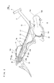
- Fig. 1 is a right side view of the underbone motorcycle 1 according to the present preferred embodiment of the present invention.
- a head pipe 2 is provided at the front part of the vehicle.
- a pair of front forks 6 is provided under the head pipe 2.
- a front wheel 7 is rotatably attached to the lower ends of the pair of front forks 6.
- a front fender 8 used to cover the upper part of the front wheel 7 is provided above the front wheel 7.
- a handle 9 is rotatably attached to the upper part of the head pipe 2.
- a back mirror 10 is attached to a side of the handle 9.
- a head light 11 is provided in front of the handle 9.
- the engine 15 is provided under the main frame 3.
- the engine 15 includes a cylinder portion 15a.
- the cylinder axial line 100 of the cylinder portion 15a is inclined forward with respect to the vertical line.
- Support plates 16 and 17 are attached to the main frame 3.
- the engine 15 is supported at the main frame 3 as it is fixed to the support plates 16 and 17.
- Fig. 2 is a right side view of a structure of a periphery of a body frame of the motorcycle 1.
- the front end of the main frame 3 is connected to the rear part of the head pipe 2.
- the main frame 3 extends backward and downward.
- a seat frame 4 that extends backward and upward from the main frame 3 is attached to the main frame 3.
- a back frame 5 that extends backward and upward is attached to the rear end of the main frame 3.
- the rear end of the back frame 5 is connected to the seat frame 4.
- the main frame 3, the seat frame 4 and the back frame 5 form a "body frame" according to the present invention.
- the main frame 3 is an example of a "front frame” according to the present invention.
- a seat 12 is provided above the seat frame 4.
- a storage box 13 used to store a baggage and the like and a fuel tank 14 are provided between the seat 12 and the seat frame 4.
- the fuel tank 14 is supported by the seat frame 4.
- the seat 12 is indirectly supported by the seat frame 4.
- the front end 14a of the fuel tank 14 is provided behind (opposite to the direction of the arrow FWD) the front end 12a of the seat 12.
- the engine 15 is at least partly provided ahead of the front end 12a of the seat 12. More specifically, the cylinder portion 15a that emits the largest amount of heat in the engine 15 and a part of the crankcase 15b are provided ahead of the front end 12a of the seat 12.
- a canister 25 is provided under the fuel tank 14.
- the canister 25 is provided along the lower end surface 14d of the fuel tank 14 under the upper end surface 14c of the fuel tank 14.
- the canister 25 stores evaporated fuel gas supplied from the fuel tank 14 and guides the fuel gas to the engine 15 through a carburetor 30 (see Fig. 1 ) that will be described.
- the canister 25 is provided behind the front end 12a of the seat 12.
- the canister 25 includes activated carbon particles (not shown).
- the activated carbon particles adsorb evaporated fuel gas supplied from the fuel tank 14 and coming into the canister 25.
- negative pressure is generated as the piston (not shown) reciprocates in the cylinder portion 15a of the engine 15.
- the fuel gas adsorbed by the activated carbon particles in the canister 25 is discharged into the carburetor 30 by the generated negative pressure.
- Fig. 3 is a left side view of a structure of a periphery of the body frame of the motorcycle 1.
- an air cleaner 29 used to clean air that is sent into the engine 15 is provided behind the head pipe 2.
- the air cleaner 29 is connected with the carburetor 30 that supplies fuel to the engine 15.
- the carburetor 30 is an example of a "fuel supply device" according to the present invention.
- the carburetor 30 is provided ahead (in the direction of the arrow FWD) of the front end 12a of the seat 12 and under the canister 25 as shown in Fig. 1 .
- an air inlet pipe 31 arranged to connect the carburetor 30 and the engine 15 is provided between the carburetor 30 and the engine 15.
- a rubber supply hose 32 used to supply fuel from the fuel tank 14 is connected to the carburetor 30.
- a pivot axis 18 is provided at the support plate 17 connected to the main frame 3.
- the front end of the rear arm 19 is supported by the pivot axis 18 and the rear arm 19 can swing in the vertical direction.
- the rear wheel 20 is rotatably provided at the rear end of the rear arm 19.
- the rear arm 19 is supported by the seat frame 4 through the rear cushion member 21.
- a rear fender 22 used to prevent the splashing of mud or pebbles by the rear wheel 20 during traveling are provided under the seat 12.
- a tail lamp 23 is attached at the rear part of the rear fender 22.
- a side cover 24 is attached to cover a side of the rear fender 22.
- the fuel tank 14 is provided above the rear fender 22.
- a rollover valve 26 is provided between the fuel tank 14 and the canister 25.
- the rollover valve 26 shuts the flow path for fuel from the fuel tank 14 to the canister 25 to prevent the liquid fuel from coming into the canister 25 when the motorcycle 1 is rolled over.
- the rollover valve 26 is an example of an "inflow control valve" according to the present invention.
- the rollover valve 26 is provided behind and above the canister 25.
- the rollover valve 26 is provided under the upper end surface 14c of the fuel tank 14 and above a charge port 25b of the canister 25.
- Fig. 4 is a plan view of a structure of a periphery of the canister 25.
- a purge port 25c of the canister 25 is connected with one end of a rubber purge hose 33 used to connect the canister 25 and the carburetor 30.
- the purge hose 33 is an example of a "fuel supply pipe" according to the present invention.
- Fuel gas supplied from the fuel tank 14 and adsorbed by the activated carbon particles in the canister 25 is supplied to the carburetor 30 through the purge hose 33.
- the fuel gas adsorbed and stored in the activated carbon particles in the canister 25 is sucked into the carburetor 30 through the purge hose 33 by negative pressure generated when the engine 15 is driven.
- the fuel gas sucked into the carburetor 30 is discharged into the engine 15.
- the purge hose 33 is arranged to extend upward from the purge port 25c of the canister 25 and then downward along the seat frame 4 toward the front.
- the release port 25d of the canister 25 is connected with one end of a rubber release hose 34.
- the release hose 34 extends to the bottom of the engine 15.
- the release hose 34 serves to let the space in the canister open to the air in order to prevent negative pressure from being generated in the canister 25.
- the release hose 34 also serves to prevent incoming liquid fuel into the canister 25 from adhering to the vehicle body.
- Fig. 5 is a plan view of the rear fender 22.
- the rear fender 22 has right and left inclined surfaces 22a.
- the inclined surfaces 22a are each inclined forward and downward.
- the inclined surface 22a in the rear fender 22 has two integrally formed ribs, a positioning rib 22c and an attachment rib 22d.
- the positioning rib 22c is provided to position the canister 25.
- the attachment rib 22d is provided to attach the rollover valve 26.
- the inclined surface 22a in the rear fender 22 is provided with attachment holes 22e and 22f used to attach the canister 25.
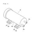
- Figs. 6 and 7 are perspective views of the canister 25.
- the canister 25 has a body case 25a that includes activated carbon particles used to adsorb fuel gas supplied from the fuel tank 14.
- the body case 25a includes the charge port 25b arranged to take in fuel gas and the purge port 25c arranged to guide the fuel gas in the body case 25a to the carburetor 30.
- the body case 25a is provided with a release port 25d used to prevent negative pressure from being generated in the body case 25a.
- the body case 25a of the canister 25 includes attachment mounts 25e and 25f used to attach the canister 25 to the rear fender 22.
- the attachment mounts 25e and 25f are provided with attachment holes 25g and 25h.
- Fig. 8 is a perspective view of a rear part of the motorcycle 1 showing a structure of a periphery of the canister 25.
- Fig. 9 is a perspective view of the rear fender. As shown in Fig. 8 , the canister 25 is attached to the inclined surface 22a of the fear fender 22.
- the canister 25 is provided so that the charge port 25b and the purge port 25c are provided at its back side and the release port 25d is provided at its front side. More specifically, the charge port 25b and the purge port 25c are provided on the rear side of the canister 25 inclined forward.
- the release port 25d is provided on the front side of the canister 25 inclined forward.
- the charge port 25b is an example of an "input port” according to the present invention and the purge port 25c is an example of an "output port” according to the present invention.
- the release port 25d is an example of a "discharge port" according to the present invention.
- the canister 25 is positioned as the attachment mounts 25e and 25f are abutted against the two positioning ribs 22c formed at the inclined surface 22a. While the attachment mounts 25e and 25f are positioned, the positions of the attachment holes 25g and 25h of the canister 25 are matched to the positions of the attachment holes 22e and 22f of the rear fender 22. When a bolt 50 (see Fig. 11 ) is tightened as the attachment holes are thus registered, the canister 25 is fixed to the rear fender 22. In this way, the canister 25 is attached as it is inclined forward along the inclined surface 22a formed at the rear fender 22.
- the canister 25 is positioned between the front end 14a and the rear end 14b of the fuel tank 14 behind (opposite to the direction of the arrow FWD) the front end 12a of the seat 12 as shown in Fig. 1 .
- the rollover valve 26 has an attachment portion 26a inserted into the attachment rib 22d of the fender 22.
- the insertion of the attachment portion 26a into the attachment rib 22d allows the rollover valve 26 to be attached to the rear fender 22.
- a rubber charge hose 27 used to connect the fuel tank 14 and the rollover valve 26 is provided between the fuel tank 14 and the rollover valve 26.
- a rubber charge hose 28 is provided between the rollover valve 26 and the canister 25. The charge hose 28 is connected to the charge port 25b of the canister 25.
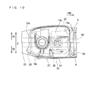
- Fig. 10 is a plan view of the fuel tank 14.
- the canister 25 is provided on the inner side than the outermost part of the fuel tank 14 on the both sides in the widthwise direction (X-direction). More specifically, according to the present preferred embodiment, the canister 25 is provided on the inner side than a flange 14e provided at the edge of the fuel tank 14. The canister 25 is provided to overlap the fuel tank 14 when seen in a plan view.
- a ventilation port 14f is provided at the upper end surface 14c of the fuel tank 14.
- the charge hose 27 is connected to the ventilation port 14f.
- the charge hose 27 is arranged to extend backward and downward from the ventilation port 14f provided at the upper end surface 14c of the fuel tank 14 and connected to the rollover valve 26. More specifically, the input port of the rollover valve 26 is positioned under the ventilation port 14f of the fuel tank 14.
- the charge hose 28 is arranged to extend forward and downward from the output port of the rollover valve 26 and connected to the canister 25. More specifically, the charge port 25b of the canister 25 is positioned under the output port of the rollover valve 26.
- the ventilation port 14f is provided on the right side of the vehicle (in the direction of the arrow X2).
- the side stand 40 (see Fig. 3 ) of the motorcycle 1 is provided on the left side of the vehicle. Since the side stand 40 is provided on the left side of the vehicle, the vehicle is inclined to the left when it is stopped.
- the ventilation port 14f is provided on the right side of the vehicle, fuel does not overflow from the ventilation port 14f when the vehicle is inclined.
- the canister 25 and the rollover valve 26 are provided on the right side of the vehicle, the length of the charge hose 27 can be reduced. More specifically, the canister 25 is provided on the opposite side to the side provided with the side stand 40, so that piping process for the charge hose is alleviated.
- the charge hose 27, the rollover valve 26, the charge hose 28, the canister 25 and the purge hose 33 are connected and assembled, and then they are mounted on the seat frame 4 and the rear fender 22.
- the operation of removing the rear fender 22 or the like becomes complicated. The maintenance is improved by handling these components after they are assembled.
- Fig. 11 is a sectional view of the rear part of the motorcycle 1.
- Fig. 11 is a sectional view taken along line 200-200 in Fig. 1 .
- the rear fender 22 includes the right and left inclined surfaces 22a and a central concave portion 22b.
- the concave portion 22b extends upward as it avoids the rear wheel 20.
- the central surface 80 shown in Figs. 10 and 11 passes through the center of the rear wheel 20 with respect to the widthwise direction of the vehicle.
- the canister 25 is provided more on the right side (in the direction of the arrow X2) than the central surface 80. Stated differently, the canister 25 is provided on the right side so that it does not overlap the central surface 80.
- the rear fender 22 has the concave portion 22b in the center in the widthwise direction of the vehicle.
- the canister 25 is provided on the right side of the concave portion 22b of the rear fender 22 and at the inclined surface 22a under the upper end 22g of the concave portion 22b.
- the canister 25 is provided at the inclined surface 22a on the right side avoiding the central concave portion 22b, so that the height of the vehicle can be kept from increasing.
- the canister 25 is attached to the rear fender 22 as it is arranged on the inner side than the outer side surface 4a of the seat frame 4.
- the rollover valve 26 is attached to the rear fender 22 as it is provided on the inner side than the outside surface 4a of the seat frame 4.
- the motorcycle includes the canister 25 that stores evaporated fuel gas supplied from the fuel tank 14 and supplies the stored fuel gas to the engine 15.
- the canister 25 is provided to at least partly overlap the fuel tank 14 behind the front end 12a of the seat 12 when seen in a plan view.
- the canister 25 can be provided behind the front end 12a of the seat 12 while the vehicle size can be prevented from increasing.
- the fuel tank 14 is positioned behind the front end 12a of the seat 12, so that a concave space can be formed above the engine 15. This makes it easier for the rider to get on/off the vehicle.
- the engine 15 is provided at least partly ahead of the front end 12a of the seat 12 and the canister 25 is provided behind the front end 12a of the seat 12.
- the canister 25 can be provided away from the engine 15 that emits heat, so that the canister 25 can be less affected by heat from the engine 15.
- the motorcycle according to the present preferred embodiment includes the rear fender 22 provided to cover the rear wheel 20 from above and support the canister 25 and the fuel tank 14 from below.
- the rear fender 22 includes the inclined surface 22a inclined forward and downward, the canister 25 is provided as it is inclined along the inclined surface 22a. Liquid fuel is sometimes stored in the canister 25, but the amount of liquid fuel to remain in the canister 25 can be reduced because the canister 25 is inclined.
- the inclined surface 22a formed at the rear fender 22 is used as it is and therefore the inclination arrangement of the canister 25 can be formed less costly.
- the rear fender 22 includes a concave portion 22b that extends upward to avoid the rear wheel 20 above the rear wheel 20 and the inclined surface 22a is provided at a side of the concave portion 22b with respect to the widthwise direction of the vehicle.
- the rear fender 22 is provided with the canister 25 and still the height of the vehicle can be kept from increasing.
- the charge port 25b is provided at the rear side of the canister 25 inclined forward. This alleviates piping to the fuel tank 14 provided above the canister 25.
- the release port 25d is provided on the front side of the canister 25 inclined forward. This makes it easier to provide a release hose extending downward.
- the positioning rib 22c used to position the canister 25 is integrally provided to the inclined surface 22a. In this way, the canister 25 can be fixed with a reduced number of parts.
- the canister 25 is provided so that it does not overlap the central surface of the rear wheel 20 with respect to the widthwise direction of the vehicle when seen in a plan view. As the canister is shifted from the rear wheel 20 in this way, the height of the vehicle body can be prevented from increasing because of the attached canister 25.
- the canister 25 is provided at the inclined surface 22a opposite to the stand with respect to the widthwise direction of the motorcycle 1.
- the ventilation port 14f of the fuel tank 14 is provided on the opposite side to the inclined side of the vehicle.
- the ventilation port 14f of the fuel tank 14 is closely positioned to the canister 25, so that the length of the pipe can be shortened.
- the canister 25 is provided between the front end 14a and the rear end 14b of the fuel tank 14.
- the length of the vehicle can be prevented from increasing when the canister 25 is provided.
- the carburetor 30 arranged to supply fuel to the engine 15 is provided ahead of the front end 12a of the seat 12 and under the canister 25.
- the canister 25 and the carburetor 30 are connected by the purge hose 33 arranged to send fuel gas from the canister 25 to the carburetor 30.
- the purge hose 33 extends at a downward incline. In this way, evaporated fuel can be prevented from remaining in the supply pipe extended from the canister 25 to the carburetor 33.
- the canister 25 includes the purge port 25c connected to the purge hose 33 and the purge port 25c of the canister 25 is provided on the rear side of the canister 25.
- the purge port 25c can be set in a high position, so that the pipe connected to the carburetor 30 can be inclined downward entirely.
- the liquid fuel can be kept from being flowed from the purge port 25c.
- the rollover valve 26 is provided in the path from the fuel tank 14 to the canister 25 to release tank pressure and prevent liquid fuel from coming into the canister 25 from the fuel tank 14 when the vehicle is rolled over.
- the input port of the rollover valve 26 is provided under the ventilation port 14f of the fuel tank 14, and the charge port 25b of the canister 25 is provided under the output port of the rollover valve 26. Liquefied fuel can be prevented from remaining in the pipes connecting the fuel tank 14 and the rollover valve 26 and the rollover valve 26 and the canister 25.
- the rollover valve 26 is attached to the rear fender 22.
- the number of parts can be reduced because no special member is used to provide the rollover valve 26.
- the attachment rib 22d used to attach the rollover valve 26 is integrally provided to the rear fender 22.
- the number of parts can be reduced because no special member is used to provide the rollover valve 26.
- the canister 25 and the rollover valve 26 are provided on the inner side than the outer surface of the seat frame 4.
- the canister 25 and the rollover valve 26 can be protected.
- the rear fender 22 can be prevented from increasing in size in the widthwise direction because of the canister 25 and the rollover valve 26.
- the underbone motorcycle having a main frame whose height is small is used as an example of the motorcycle.
- the present invention is not limited to the type of the motorcycle but can be applied to other motorcycles such as a scooter motorcycle that include a canister used to store evaporated fuel gas supplied from a fuel tank.
- the canister is provided behind the front end of the seat and between the front end and the rear end of the fuel tank as an example.
- the present invention is not limited to the arrangement and the canister can be provided ahead of the front end of the fuel tank if the position is behind the front end of the seat.
- the canister is provided under the upper end surface of the fuel tank and along the lower surface of the fuel tank as an example.
- the present invention is not limited to the arrangement and the canister may be provided in a position such as in a storage box as long as the position is behind the front end of the seat and ahead of the rear end of the fuel tank.
- the rollover valve is provided between the fuel tank and the canister as an example.
- the present invention is not limited to the arrangement and the fuel tank and the canister can be connected directly by a charge hose without providing the rollover valve.
- the rollover valve is attached as it is inserted to the attachment rib provided at the rear fender.
- the present invention is not limited to the arrangement and methods other than the insertion to the attachment rib such as screw-bolting using a bolt may be employed to attach the rollover valve to the rear fender.
- the carburetor is described as an example of the fuel supply device, but the present invention is not limited to the example and an injector used to supply fuel to the engine by electronic control may be used.
- the purge hose is connected to an air inlet pipe in the periphery of the injector.
- the canister is inclined forward and obliquely downward as an example.
- the present invention is not limited to the arrangement, and the canister may be arranged in the vertical direction so that the release port is positioned at the lower surface.
Landscapes
- Engineering & Computer Science (AREA)
- Mechanical Engineering (AREA)
- Chemical & Material Sciences (AREA)
- Combustion & Propulsion (AREA)
- General Engineering & Computer Science (AREA)
- Supplying Secondary Fuel Or The Like To Fuel, Air Or Fuel-Air Mixtures (AREA)
- Automatic Cycles, And Cycles In General (AREA)
- Cooling, Air Intake And Gas Exhaust, And Fuel Tank Arrangements In Propulsion Units (AREA)
Description
- The present invention relates to motorcycles, and more specifically to a motorcycle including a canister that stores vaporized fuel gas.
- There is a known motorcycle including a canister that stores vaporized fuel gas supplied from a fuel tank. For example, Japanese Patent No.
2992005 JP 10-324281 A - Japanese Patent No.
2992005 2992005 - The motorcycle disclosed by Japanese Patent No.
2992005 - While the scooter motorcycle is provided with the unit swing type engine, there is a known underbone motorcycle having an engine directly fixed to a frame. In the underbone motorcycle, components that swing with respect to the frame have reduced weight so that the traveling performance is improved.
- The engine of the underbone motorcycle is provided ahead of the front end of the seat. Since the engine is provided in the front part, it is harder to get on and off the underbone motorcycle than the scooter motorcycle. It is desirable that the underbone motorcycle forms a concave space ahead of the seat and above the engine in order to make it easier for the rider to get on/off the vehicle. In the underbone motorcycle, the fuel tank is provided under the seat and a concave space is formed above the engine.
- In the underbone motorcycle, for example, a canister as disclosed by Japanese Patent No.
2992005 2992005 -
JP 52 083154 independent claim 1.JP 53 131121 U -
JP 43 72484 A - It is an object of the invention to provide an improved motorcycle that has a compact body even when a canister is provided.
- This object is achieved by a motorcycle according to
claim 1. - The canister can be prevented from protruding behind the fuel tank. When the canister is provided, the body size in the front-back direction can be prevented from increasing. In other words, the vehicle body can be made compact.
- Other features, elements, steps, characteristics and advantages of the present invention will become more apparent from the following detailed description of the preferred embodiments of the present invention with reference to the attached drawings.
-
-
Fig. 1 is a right side view of an entire structure of a motorcycle according to a preferred embodiment of the present invention. -
Fig. 2 is a right side view of a structure of a periphery of a body frame in the motorcycle according to the preferred embodiment. -
Fig. 3 is a left side view of a structure of a periphery of the body frame in the motorcycle according to the preferred embodiment. -
Fig. 4 is a plan view of a structure of a periphery of a canister in the motorcycle according to the preferred embodiment. -
Fig. 5 is a plan view of a rear fender included in the motorcycle according to the preferred embodiment. -
Fig. 6 is a perspective view of the canister provided in the motorcycle according to the preferred embodiment. -
Fig. 7 is a perspective view of the canister provided in the motorcycle according to the preferred embodiment. -
Fig. 8 is a perspective view of a structure of a periphery of the canister in the motorcycle according to the preferred embodiment. -
Fig. 9 is a perspective view of the rear fender included in the motorcycle according to the preferred embodiment. -
Fig. 10 is a plan view of a fuel tank provided in the motorcycle according to the preferred embodiment. -
Fig. 11 is a front sectional view of the motorcycle taken along line 200-200 inFig. 1 . - Now, a preferred embodiment of the present invention will be described with reference to the accompanying drawings. According to the present preferred embodiment, an
underbone motorcycle 1 will be described as an example of the motorcycle according to the present invention. The underbone motorcycle has a frame (main frame) arranged at a low position between the seat and the handle. The rider can easily stride across the underbone motorcycle for the low frame position. - In the drawings, the arrow FWD refers to the forward direction in the advancing direction of the
motorcycle 1. In the following description of the present preferred embodiment, the front-back and right-left directions refer to these directions in connection with the advancing direction of the vehicle unless otherwise specified. More specifically, in the following description, the forward direction viewed from a rider seated on the seat refers to the forward direction of the motorcycle, and the right or left direction viewed from a rider seated on the seat refers to the right or left direction of the motorcycle. -
Fig. 1 is a right side view of theunderbone motorcycle 1 according to the present preferred embodiment of the present invention. As shown inFig. 1 , ahead pipe 2 is provided at the front part of the vehicle. A pair offront forks 6 is provided under thehead pipe 2. Afront wheel 7 is rotatably attached to the lower ends of the pair offront forks 6. Afront fender 8 used to cover the upper part of thefront wheel 7 is provided above thefront wheel 7. Ahandle 9 is rotatably attached to the upper part of thehead pipe 2. Aback mirror 10 is attached to a side of thehandle 9. Ahead light 11 is provided in front of thehandle 9. - The
engine 15 is provided under themain frame 3. Theengine 15 includes acylinder portion 15a. The cylinderaxial line 100 of thecylinder portion 15a is inclined forward with respect to the vertical line.Support plates main frame 3. Theengine 15 is supported at themain frame 3 as it is fixed to thesupport plates -
Fig. 2 is a right side view of a structure of a periphery of a body frame of themotorcycle 1. As shown inFig. 2 , the front end of themain frame 3 is connected to the rear part of thehead pipe 2. Themain frame 3 extends backward and downward. Aseat frame 4 that extends backward and upward from themain frame 3 is attached to themain frame 3. Aback frame 5 that extends backward and upward is attached to the rear end of themain frame 3. The rear end of theback frame 5 is connected to theseat frame 4. Themain frame 3, theseat frame 4 and theback frame 5 form a "body frame" according to the present invention. Themain frame 3 is an example of a "front frame" according to the present invention. - Referring back to
Fig. 1 , aseat 12 is provided above theseat frame 4. Astorage box 13 used to store a baggage and the like and afuel tank 14 are provided between theseat 12 and theseat frame 4. Thefuel tank 14 is supported by theseat frame 4. Theseat 12 is indirectly supported by theseat frame 4. Thefront end 14a of thefuel tank 14 is provided behind (opposite to the direction of the arrow FWD) thefront end 12a of theseat 12. - The
engine 15 is at least partly provided ahead of thefront end 12a of theseat 12. More specifically, thecylinder portion 15a that emits the largest amount of heat in theengine 15 and a part of thecrankcase 15b are provided ahead of thefront end 12a of theseat 12. - As shown in
Fig. 2 , acanister 25 is provided under thefuel tank 14. Thecanister 25 is provided along thelower end surface 14d of thefuel tank 14 under theupper end surface 14c of thefuel tank 14. Thecanister 25 stores evaporated fuel gas supplied from thefuel tank 14 and guides the fuel gas to theengine 15 through a carburetor 30 (seeFig. 1 ) that will be described. Thecanister 25 is provided behind thefront end 12a of theseat 12. - The
canister 25 includes activated carbon particles (not shown). The activated carbon particles adsorb evaporated fuel gas supplied from thefuel tank 14 and coming into thecanister 25. When theengine 15 is driven, negative pressure is generated as the piston (not shown) reciprocates in thecylinder portion 15a of theengine 15. The fuel gas adsorbed by the activated carbon particles in thecanister 25 is discharged into thecarburetor 30 by the generated negative pressure. -
Fig. 3 is a left side view of a structure of a periphery of the body frame of themotorcycle 1. As shown inFig. 3 , anair cleaner 29 used to clean air that is sent into theengine 15 is provided behind thehead pipe 2. Theair cleaner 29 is connected with thecarburetor 30 that supplies fuel to theengine 15. Thecarburetor 30 is an example of a "fuel supply device" according to the present invention. Thecarburetor 30 is provided ahead (in the direction of the arrow FWD) of thefront end 12a of theseat 12 and under thecanister 25 as shown inFig. 1 . - As shown in
Fig. 3 , anair inlet pipe 31 arranged to connect thecarburetor 30 and theengine 15 is provided between thecarburetor 30 and theengine 15. Arubber supply hose 32 used to supply fuel from thefuel tank 14 is connected to thecarburetor 30. - As shown in
Fig. 1 , apivot axis 18 is provided at thesupport plate 17 connected to themain frame 3. The front end of therear arm 19 is supported by thepivot axis 18 and therear arm 19 can swing in the vertical direction. Therear wheel 20 is rotatably provided at the rear end of therear arm 19. Therear arm 19 is supported by theseat frame 4 through therear cushion member 21. - As shown in
Fig. 1 , arear fender 22 used to prevent the splashing of mud or pebbles by therear wheel 20 during traveling are provided under theseat 12. Atail lamp 23 is attached at the rear part of therear fender 22. Aside cover 24 is attached to cover a side of therear fender 22. Thefuel tank 14 is provided above therear fender 22. - As shown in
Fig. 2 , arollover valve 26 is provided between thefuel tank 14 and thecanister 25. Therollover valve 26 shuts the flow path for fuel from thefuel tank 14 to thecanister 25 to prevent the liquid fuel from coming into thecanister 25 when themotorcycle 1 is rolled over. Therollover valve 26 is an example of an "inflow control valve" according to the present invention. Therollover valve 26 is provided behind and above thecanister 25. Therollover valve 26 is provided under theupper end surface 14c of thefuel tank 14 and above acharge port 25b of thecanister 25. -
Fig. 4 is a plan view of a structure of a periphery of thecanister 25. As shown inFig. 4 , apurge port 25c of thecanister 25 is connected with one end of arubber purge hose 33 used to connect thecanister 25 and thecarburetor 30. Thepurge hose 33 is an example of a "fuel supply pipe" according to the present invention. Fuel gas supplied from thefuel tank 14 and adsorbed by the activated carbon particles in thecanister 25 is supplied to thecarburetor 30 through thepurge hose 33. The fuel gas adsorbed and stored in the activated carbon particles in thecanister 25 is sucked into thecarburetor 30 through thepurge hose 33 by negative pressure generated when theengine 15 is driven. The fuel gas sucked into thecarburetor 30 is discharged into theengine 15. - As shown in
Fig. 2 , thepurge hose 33 is arranged to extend upward from thepurge port 25c of thecanister 25 and then downward along theseat frame 4 toward the front. - As shown in
Figs. 2 and4 , therelease port 25d of thecanister 25 is connected with one end of arubber release hose 34. As shown inFig. 2 , therelease hose 34 extends to the bottom of theengine 15. Therelease hose 34 serves to let the space in the canister open to the air in order to prevent negative pressure from being generated in thecanister 25. Therelease hose 34 also serves to prevent incoming liquid fuel into thecanister 25 from adhering to the vehicle body. -
Fig. 5 is a plan view of therear fender 22. Therear fender 22 has right and leftinclined surfaces 22a. Theinclined surfaces 22a are each inclined forward and downward. As shown inFig. 5 , theinclined surface 22a in therear fender 22 has two integrally formed ribs, apositioning rib 22c and anattachment rib 22d. Thepositioning rib 22c is provided to position thecanister 25. Theattachment rib 22d is provided to attach therollover valve 26. Theinclined surface 22a in therear fender 22 is provided withattachment holes canister 25. -
Figs. 6 and7 are perspective views of thecanister 25. As shown inFigs. 6 and7 , thecanister 25 has abody case 25a that includes activated carbon particles used to adsorb fuel gas supplied from thefuel tank 14. As shown inFig. 7 , thebody case 25a includes thecharge port 25b arranged to take in fuel gas and thepurge port 25c arranged to guide the fuel gas in thebody case 25a to thecarburetor 30. As shown inFig. 6 , thebody case 25a is provided with arelease port 25d used to prevent negative pressure from being generated in thebody case 25a. - The
body case 25a of thecanister 25 includes attachment mounts 25e and 25f used to attach thecanister 25 to therear fender 22. The attachment mounts 25e and 25f are provided withattachment holes -
Fig. 8 is a perspective view of a rear part of themotorcycle 1 showing a structure of a periphery of thecanister 25.Fig. 9 is a perspective view of the rear fender. As shown inFig. 8 , thecanister 25 is attached to theinclined surface 22a of thefear fender 22. - The
canister 25 is provided so that thecharge port 25b and thepurge port 25c are provided at its back side and therelease port 25d is provided at its front side. More specifically, thecharge port 25b and thepurge port 25c are provided on the rear side of thecanister 25 inclined forward. Therelease port 25d is provided on the front side of thecanister 25 inclined forward. Thecharge port 25b is an example of an "input port" according to the present invention and thepurge port 25c is an example of an "output port" according to the present invention. Therelease port 25d is an example of a "discharge port" according to the present invention. - As shown in
Fig. 8 , thecanister 25 is positioned as the attachment mounts 25e and 25f are abutted against the twopositioning ribs 22c formed at theinclined surface 22a. While the attachment mounts 25e and 25f are positioned, the positions of the attachment holes 25g and 25h of thecanister 25 are matched to the positions of the attachment holes 22e and 22f of therear fender 22. When a bolt 50 (seeFig. 11 ) is tightened as the attachment holes are thus registered, thecanister 25 is fixed to therear fender 22. In this way, thecanister 25 is attached as it is inclined forward along theinclined surface 22a formed at therear fender 22. - According to the present preferred embodiment, the
canister 25 is positioned between thefront end 14a and therear end 14b of thefuel tank 14 behind (opposite to the direction of the arrow FWD) thefront end 12a of theseat 12 as shown inFig. 1 . - As shown in
Fig. 8 , therollover valve 26 has anattachment portion 26a inserted into theattachment rib 22d of thefender 22. The insertion of theattachment portion 26a into theattachment rib 22d allows therollover valve 26 to be attached to therear fender 22. - As shown in
Figs. 2 and8 , arubber charge hose 27 used to connect thefuel tank 14 and therollover valve 26 is provided between thefuel tank 14 and therollover valve 26. Arubber charge hose 28 is provided between therollover valve 26 and thecanister 25. Thecharge hose 28 is connected to thecharge port 25b of thecanister 25. -
Fig. 10 is a plan view of thefuel tank 14. As shown inFig. 10 , thecanister 25 is provided on the inner side than the outermost part of thefuel tank 14 on the both sides in the widthwise direction (X-direction). More specifically, according to the present preferred embodiment, thecanister 25 is provided on the inner side than aflange 14e provided at the edge of thefuel tank 14. Thecanister 25 is provided to overlap thefuel tank 14 when seen in a plan view. - As shown in
Fig. 10 , aventilation port 14f is provided at theupper end surface 14c of thefuel tank 14. Thecharge hose 27 is connected to theventilation port 14f. - As shown in
Figs. 2 and8 , thecharge hose 27 is arranged to extend backward and downward from theventilation port 14f provided at theupper end surface 14c of thefuel tank 14 and connected to therollover valve 26. More specifically, the input port of therollover valve 26 is positioned under theventilation port 14f of thefuel tank 14. Thecharge hose 28 is arranged to extend forward and downward from the output port of therollover valve 26 and connected to thecanister 25. More specifically, thecharge port 25b of thecanister 25 is positioned under the output port of therollover valve 26. - As shown in
Fig. 10 , according to the present preferred embodiment, theventilation port 14f is provided on the right side of the vehicle (in the direction of the arrow X2). The side stand 40 (seeFig. 3 ) of themotorcycle 1 is provided on the left side of the vehicle. Since the side stand 40 is provided on the left side of the vehicle, the vehicle is inclined to the left when it is stopped. Theventilation port 14f is provided on the right side of the vehicle, fuel does not overflow from theventilation port 14f when the vehicle is inclined. Thecanister 25 and therollover valve 26 are provided on the right side of the vehicle, the length of thecharge hose 27 can be reduced. More specifically, thecanister 25 is provided on the opposite side to the side provided with theside stand 40, so that piping process for the charge hose is alleviated. - According to the present preferred embodiment, the
charge hose 27, therollover valve 26, thecharge hose 28, thecanister 25 and thepurge hose 33 are connected and assembled, and then they are mounted on theseat frame 4 and therear fender 22. When these components are separately assembled in therear fender 22 and theseat frame 4, the operation of removing therear fender 22 or the like becomes complicated. The maintenance is improved by handling these components after they are assembled. -
Fig. 11 is a sectional view of the rear part of themotorcycle 1.Fig. 11 is a sectional view taken along line 200-200 inFig. 1 . As shown inFig. 11 , therear fender 22 includes the right and leftinclined surfaces 22a and a centralconcave portion 22b. Theconcave portion 22b extends upward as it avoids therear wheel 20. - The
central surface 80 shown inFigs. 10 and11 passes through the center of therear wheel 20 with respect to the widthwise direction of the vehicle. Thecanister 25 is provided more on the right side (in the direction of the arrow X2) than thecentral surface 80. Stated differently, thecanister 25 is provided on the right side so that it does not overlap thecentral surface 80. - The
rear fender 22 has theconcave portion 22b in the center in the widthwise direction of the vehicle. As shown inFig. 11 , thecanister 25 is provided on the right side of theconcave portion 22b of therear fender 22 and at theinclined surface 22a under theupper end 22g of theconcave portion 22b. Thecanister 25 is provided at theinclined surface 22a on the right side avoiding the centralconcave portion 22b, so that the height of the vehicle can be kept from increasing. - As shown in
Fig. 11 , thecanister 25 is attached to therear fender 22 as it is arranged on the inner side than theouter side surface 4a of theseat frame 4. Therollover valve 26 is attached to therear fender 22 as it is provided on the inner side than theoutside surface 4a of theseat frame 4. - As in the foregoing, the motorcycle according to present preferred embodiment includes the
canister 25 that stores evaporated fuel gas supplied from thefuel tank 14 and supplies the stored fuel gas to theengine 15. Thecanister 25 is provided to at least partly overlap thefuel tank 14 behind thefront end 12a of theseat 12 when seen in a plan view. In themotorcycle 1 having thefuel tank 14 positioned behind thefront end 12a of theseat 12, thecanister 25 can be provided behind thefront end 12a of theseat 12 while the vehicle size can be prevented from increasing. Thefuel tank 14 is positioned behind thefront end 12a of theseat 12, so that a concave space can be formed above theengine 15. This makes it easier for the rider to get on/off the vehicle. - As in the foregoing, the
engine 15 is provided at least partly ahead of thefront end 12a of theseat 12 and thecanister 25 is provided behind thefront end 12a of theseat 12. Thecanister 25 can be provided away from theengine 15 that emits heat, so that thecanister 25 can be less affected by heat from theengine 15. - The motorcycle according to the present preferred embodiment includes the
rear fender 22 provided to cover therear wheel 20 from above and support thecanister 25 and thefuel tank 14 from below. Therear fender 22 includes theinclined surface 22a inclined forward and downward, thecanister 25 is provided as it is inclined along theinclined surface 22a. Liquid fuel is sometimes stored in thecanister 25, but the amount of liquid fuel to remain in thecanister 25 can be reduced because thecanister 25 is inclined. Theinclined surface 22a formed at therear fender 22 is used as it is and therefore the inclination arrangement of thecanister 25 can be formed less costly. - According to the present preferred embodiment, the
rear fender 22 includes aconcave portion 22b that extends upward to avoid therear wheel 20 above therear wheel 20 and theinclined surface 22a is provided at a side of theconcave portion 22b with respect to the widthwise direction of the vehicle. Therear fender 22 is provided with thecanister 25 and still the height of the vehicle can be kept from increasing. - According to the present preferred embodiment, the
charge port 25b is provided at the rear side of thecanister 25 inclined forward. This alleviates piping to thefuel tank 14 provided above thecanister 25. - According to the present preferred embodiment, the
release port 25d is provided on the front side of thecanister 25 inclined forward. This makes it easier to provide a release hose extending downward. - According to the present preferred embodiment, the
positioning rib 22c used to position thecanister 25 is integrally provided to theinclined surface 22a. In this way, thecanister 25 can be fixed with a reduced number of parts. - According to the present preferred embodiment, the
canister 25 is provided so that it does not overlap the central surface of therear wheel 20 with respect to the widthwise direction of the vehicle when seen in a plan view. As the canister is shifted from therear wheel 20 in this way, the height of the vehicle body can be prevented from increasing because of the attachedcanister 25. - According to the present preferred embodiment, the
canister 25 is provided at theinclined surface 22a opposite to the stand with respect to the widthwise direction of themotorcycle 1. Theventilation port 14f of thefuel tank 14 is provided on the opposite side to the inclined side of the vehicle. Theventilation port 14f of thefuel tank 14 is closely positioned to thecanister 25, so that the length of the pipe can be shortened. - According to the present preferred embodiment, the
canister 25 is provided between thefront end 14a and therear end 14b of thefuel tank 14. The length of the vehicle can be prevented from increasing when thecanister 25 is provided. - According to the present preferred embodiment, the
carburetor 30 arranged to supply fuel to theengine 15 is provided ahead of thefront end 12a of theseat 12 and under thecanister 25. Thecanister 25 and thecarburetor 30 are connected by thepurge hose 33 arranged to send fuel gas from thecanister 25 to thecarburetor 30. Thepurge hose 33 extends at a downward incline. In this way, evaporated fuel can be prevented from remaining in the supply pipe extended from thecanister 25 to thecarburetor 33. - According to the present preferred embodiment, the
canister 25 includes thepurge port 25c connected to thepurge hose 33 and thepurge port 25c of thecanister 25 is provided on the rear side of thecanister 25. Thepurge port 25c can be set in a high position, so that the pipe connected to thecarburetor 30 can be inclined downward entirely. When liquid fuel is stored in thecanister 25, the liquid fuel can be kept from being flowed from thepurge port 25c. - According to the present preferred embodiment, the
rollover valve 26 is provided in the path from thefuel tank 14 to thecanister 25 to release tank pressure and prevent liquid fuel from coming into thecanister 25 from thefuel tank 14 when the vehicle is rolled over. The input port of therollover valve 26 is provided under theventilation port 14f of thefuel tank 14, and thecharge port 25b of thecanister 25 is provided under the output port of therollover valve 26. Liquefied fuel can be prevented from remaining in the pipes connecting thefuel tank 14 and therollover valve 26 and therollover valve 26 and thecanister 25. - According to the present preferred embodiment, the
rollover valve 26 is attached to therear fender 22. The number of parts can be reduced because no special member is used to provide therollover valve 26. - According to the present preferred embodiment, the
attachment rib 22d used to attach therollover valve 26 is integrally provided to therear fender 22. The number of parts can be reduced because no special member is used to provide therollover valve 26. - According to the present preferred embodiment, the
canister 25 and therollover valve 26 are provided on the inner side than the outer surface of theseat frame 4. When themotorcycle 1 is rolled over, thecanister 25 and therollover valve 26 can be protected. Therear fender 22 can be prevented from increasing in size in the widthwise direction because of thecanister 25 and therollover valve 26. - According to the present preferred embodiment, the underbone motorcycle having a main frame whose height is small is used as an example of the motorcycle. The present invention is not limited to the type of the motorcycle but can be applied to other motorcycles such as a scooter motorcycle that include a canister used to store evaporated fuel gas supplied from a fuel tank.
- According to the present preferred embodiment, the canister is provided behind the front end of the seat and between the front end and the rear end of the fuel tank as an example. The present invention is not limited to the arrangement and the canister can be provided ahead of the front end of the fuel tank if the position is behind the front end of the seat.
- According to the present preferred embodiment, the canister is provided under the upper end surface of the fuel tank and along the lower surface of the fuel tank as an example. The present invention is not limited to the arrangement and the canister may be provided in a position such as in a storage box as long as the position is behind the front end of the seat and ahead of the rear end of the fuel tank.
- According to the present preferred embodiment, the rollover valve is provided between the fuel tank and the canister as an example. The present invention is not limited to the arrangement and the fuel tank and the canister can be connected directly by a charge hose without providing the rollover valve.
- According to the present preferred embodiment, the rollover valve is attached as it is inserted to the attachment rib provided at the rear fender. The present invention is not limited to the arrangement and methods other than the insertion to the attachment rib such as screw-bolting using a bolt may be employed to attach the rollover valve to the rear fender.
- According to the present preferred embodiment, the carburetor is described as an example of the fuel supply device, but the present invention is not limited to the example and an injector used to supply fuel to the engine by electronic control may be used. In this case, the purge hose is connected to an air inlet pipe in the periphery of the injector.
- According to the present preferred embodiment, the canister is inclined forward and obliquely downward as an example. The present invention is not limited to the arrangement, and the canister may be arranged in the vertical direction so that the release port is positioned at the lower surface.
Claims (14)
- A motorcycle (1), comprising:a head pipe (2);a body frame connected to the head pipe (2) and including a front frame (3) extending backward and downward from the head pipe (2) and a seat frame (4) extending backward and upward from the front frame (3);a seat (12) supported at the seat frame (4);an engine (15) supported at the body frame and having at least a part provided ahead of a front end (12a) of the seat (12);a fuel tank (14) arranged above the seat frame (4) and having a front end (14a) provided behind the front end (12a) of the seat (12); anda canister (25) connected to the fuel tank (14) to store evaporated fuel gas supplied from the fuel tank (14) and supply the stored fuel gas to the engine (15);
wherein the canister (25) is provided under the fuel tank (14) and the canister (25) does not overlap a central surface (80) of a rear wheel (20) with respect to a widthwise direction (X) of the motorcycle (1) when seen in a plan view;
characterized in thatthe canister (25) is located on an inner side than the outermost part (14e) of the fuel tank (14) on the both sides in the widthwise direction (X) of the motorcycle (1), andthe canister (25) has at least a part overlapping the fuel tank (14) behind the front end (12a) of the seat (12) when seen in the plan view. - The motorcycle (1) according to claim 1, further comprising:a rear fender (22) provided to cover the rear wheel (20) from above and support the canister (25) and the fuel tank (14) from below,the rear fender (22) including an inclined surface (22a) extending forward and downward, andthe canister (25) being provided inclined along the inclined surface (22a).
- The motorcycle (1) according to claim 2, wherein the rear fender (22) comprises a concave portion (22b) extending upward above the rear wheel (20), and
the inclined surface (22a) is provided at a side of the concave portion (22b) with respect to the widthwise direction (X) of the motorcycle (1). - The motorcycle (1) according to claim 2 or 3, wherein an input port (25b) of the canister (25) is provided on a rear side of the canister (25).
- The motorcycle (1) according to any one of claims 2 to 4, wherein a discharge port (25d) of the canister (25) is provided on a front side of the canister (25).
- The motorcycle (1) according to any one of claims 2 to 5, wherein a positioning rib (22c) used to position the canister (25) is integrally provided at the inclined surface (22a).
- The motorcycle (1) according to any one of claims 2 to 6, wherein the canister (25) is provided at the inclined surface (22a) opposite to a stand (40) with respect to the widthwise direction (X) of the motorcycle (1).
- The motorcycle (1) according to any one of claims 2 to 7, wherein the canister (25) is provided between the front end (14a) and the rear end (14b) of the fuel tank (14).
- The motorcycle (1) according to any one of claims 1 to 8, further comprising:a fuel supply device (30) provided ahead of the front end (12a) of the seat (12) and under the canister (25) to supply fuel to the engine (15); anda fuel supply pipe (33) arranged to connect the canister (25) and the fuel supply device (30) and supply fuel gas supplied from the canister (25) to the fuel supply device (30),the fuel supply pipe (33) extending forward and downward.
- The motorcycle (1) according to claim 9, wherein the canister (25) comprises an output port (25c) connected to the fuel supply pipe (33), and
the output port (25c) of the canister (25) is provided on a rear side of the canister (25). - The motorcycle (1) according to claim 1, further comprising an inflow control valve (26) provided in a ventilation path that connects the fuel tank (14) and the canister (25) to prevent liquid fuel from coming into the canister (25) from the fuel tank (14) when the motorcycle (1) is rolled over,
an input port of the inflow control valve (26) being provided under a ventilation port (14f) of the fuel tank (14),
an input port (25b) of the canister (25) being provided under an output port of the inflow control valve (26). - The motorcycle (1) according to claim 2, further comprising an inflow control valve (26) provided in a ventilation path that connects the fuel tank (14) and the canister (25) to prevent liquid fuel from coming into the canister (25) from the fuel tank (14) when the motorcycle (1) is rolled over,
an input port of the inflow control valve (26) being provided under a ventilation port (14f) of the fuel tank (14),
an input port (25b) of the canister (25) being provided under an output port of the inflow control valve (26),
wherein the inflow control valve (26) is attached to the rear fender (22). - The motorcycle (1) according to claim 12, wherein the rear fender (22) is integrally provided with an attachment rib (22d) used to attach the inflow control valve (26).
- The motorcycle (1) according to any one of claims 11 to 13, wherein the canister (25) and the inflow control valve (26) are provided on an inner side than an outer surface (4a) of the seat frame (4).
Applications Claiming Priority (1)
| Application Number | Priority Date | Filing Date | Title |
|---|---|---|---|
| JP2009024082A JP2010179744A (en) | 2009-02-04 | 2009-02-04 | Motorcycle |
Publications (2)
| Publication Number | Publication Date |
|---|---|
| EP2216239A1 EP2216239A1 (en) | 2010-08-11 |
| EP2216239B1 true EP2216239B1 (en) | 2015-08-19 |
Family
ID=42027913
Family Applications (1)
| Application Number | Title | Priority Date | Filing Date |
|---|---|---|---|
| EP09177344.0A Active EP2216239B1 (en) | 2009-02-04 | 2009-11-27 | Motorcycle |
Country Status (5)
| Country | Link |
|---|---|
| EP (1) | EP2216239B1 (en) |
| JP (1) | JP2010179744A (en) |
| CN (1) | CN101791997B (en) |
| ES (1) | ES2550617T3 (en) |
| TW (1) | TWI387543B (en) |
Families Citing this family (18)
| Publication number | Priority date | Publication date | Assignee | Title |
|---|---|---|---|---|
| JP5578002B2 (en) * | 2010-09-30 | 2014-08-27 | スズキ株式会社 | Canister layout in a scooter type motorcycle |
| JP5835685B2 (en) * | 2011-03-22 | 2015-12-24 | 本田技研工業株式会社 | Evaporative fuel treatment equipment for motorcycles |
| JP5837314B2 (en) * | 2011-03-22 | 2015-12-24 | 本田技研工業株式会社 | Evaporative fuel treatment equipment for motorcycles |
| JP5801142B2 (en) * | 2011-08-24 | 2015-10-28 | 本田技研工業株式会社 | Motorcycle |
| JP5719256B2 (en) * | 2011-08-31 | 2015-05-13 | 本田技研工業株式会社 | Motorcycle |
| JP5702695B2 (en) * | 2011-09-22 | 2015-04-15 | 本田技研工業株式会社 | Canister layout for saddle riding type vehicles |
| JP5721599B2 (en) * | 2011-09-28 | 2015-05-20 | 本田技研工業株式会社 | Canister layout for saddle riding type vehicles |
| CN104136312B (en) * | 2011-12-21 | 2017-05-17 | 本田技研工业株式会社 | Saddle-ride type vehicle |
| JP5889685B2 (en) * | 2012-03-22 | 2016-03-22 | 本田技研工業株式会社 | Canister layout for saddle-ride type vehicles |
| CN105189271B (en) * | 2013-01-18 | 2018-04-17 | 本田技研工业株式会社 | Tank mounting structure for motorcycle |
| JP6138514B2 (en) * | 2013-02-25 | 2017-05-31 | 本田技研工業株式会社 | Body number confirmation structure for saddle-ride type vehicles |
| JP6098355B2 (en) * | 2013-05-20 | 2017-03-22 | スズキ株式会社 | Motorcycle canister arrangement structure |
| JP2015127184A (en) * | 2013-12-27 | 2015-07-09 | 本田技研工業株式会社 | Canister arrangement structure of saddle-riding type vehicle |
| JP2016008014A (en) * | 2014-06-26 | 2016-01-18 | スズキ株式会社 | Fuel evaporation gas recovery apparatus of motor cycle |
| TWI614400B (en) * | 2015-09-30 | 2018-02-11 | 光陽工業股份有限公司 | locomotive |
| JP6824463B1 (en) | 2020-06-23 | 2021-02-03 | ヤマハ発動機株式会社 | Saddle-type vehicle |
| CN115503859B (en) * | 2021-06-07 | 2024-09-06 | Tvs电机股份有限公司 | Tank installation |
| CN116241389B (en) * | 2023-02-03 | 2024-06-07 | 重庆赛力斯新能源汽车设计院有限公司 | Connecting piece, carbon tank mounting structure and vehicle |
Family Cites Families (6)
| Publication number | Priority date | Publication date | Assignee | Title |
|---|---|---|---|---|
| JPS5534150Y2 (en) * | 1975-12-17 | 1980-08-13 | ||
| JPS53131121U (en) * | 1977-03-24 | 1978-10-18 | ||
| JP2998307B2 (en) * | 1991-06-19 | 2000-01-11 | スズキ株式会社 | Scooter evaporative gas recovery device |
| JP2992005B2 (en) | 1998-04-10 | 1999-12-20 | 本田技研工業株式会社 | Evaporative gas control device for scooter type vehicle |
| JP4190052B2 (en) * | 1998-04-27 | 2008-12-03 | ヤマハ発動機株式会社 | Engine cooling structure for scooter type vehicles |
| JP2007118628A (en) * | 2005-10-24 | 2007-05-17 | Yamaha Motor Co Ltd | Saddle riding type vehicle |
-
2009
- 2009-02-04 JP JP2009024082A patent/JP2010179744A/en active Pending
- 2009-11-27 ES ES09177344.0T patent/ES2550617T3/en active Active
- 2009-11-27 EP EP09177344.0A patent/EP2216239B1/en active Active
- 2009-12-11 CN CN 200910259117 patent/CN101791997B/en active Active
- 2009-12-11 TW TW98142643A patent/TWI387543B/en active
Also Published As
| Publication number | Publication date |
|---|---|
| TWI387543B (en) | 2013-03-01 |
| TW201033061A (en) | 2010-09-16 |
| JP2010179744A (en) | 2010-08-19 |
| ES2550617T3 (en) | 2015-11-11 |
| CN101791997A (en) | 2010-08-04 |
| CN101791997B (en) | 2013-03-20 |
| EP2216239A1 (en) | 2010-08-11 |
Similar Documents
| Publication | Publication Date | Title |
|---|---|---|
| EP2216239B1 (en) | Motorcycle | |
| JP3165481U (en) | Saddle riding vehicle | |
| US8752661B2 (en) | Saddle seat type vehicle | |
| JP5775560B2 (en) | Saddle riding | |
| US8899367B2 (en) | Saddle-ride type vehicle | |
| US8534406B2 (en) | Motorcycle | |
| TWI429822B (en) | Evaporative fuel control device for straddle type vehicles | |
| US20120247862A1 (en) | Arrangement structure of canister in motorcycle | |
| JP2010188758A (en) | Motorcycle | |
| US9809110B2 (en) | Saddle-riding type vehicle | |
| JP5957871B2 (en) | Canister layout and motorcycle | |
| TWI493104B (en) | Locomotive evaporative fuel handling device | |
| JP2015074353A (en) | Saddle-riding type vehicle | |
| US20070102216A1 (en) | Straddle-type vehicle | |
| JP6114048B2 (en) | Canister support structure for saddle-ride type vehicles | |
| JP5841032B2 (en) | Saddle riding vehicle | |
| JP5578002B2 (en) | Canister layout in a scooter type motorcycle | |
| JP6237245B2 (en) | Canister system installation structure | |
| JP2013067276A (en) | Canister arrangement structure of straddle-type vehicle | |
| JP5759847B2 (en) | Canister layout for saddle riding type vehicles | |
| JP2013060139A (en) | Canister arrangement structure in straddle type vehicle | |
| TWI525247B (en) | Locomotive evaporative fuel handling device | |
| JP6846542B2 (en) | Saddle-type vehicle | |
| JP2013067271A (en) | Canister arranging structure of saddle riding type vehicle | |
| JP2021066386A (en) | vehicle |
Legal Events
| Date | Code | Title | Description |
|---|---|---|---|
| PUAI | Public reference made under article 153(3) epc to a published international application that has entered the european phase |
Free format text: ORIGINAL CODE: 0009012 |
|
| AK | Designated contracting states |
Kind code of ref document: A1 Designated state(s): AT BE BG CH CY CZ DE DK EE ES FI FR GB GR HR HU IE IS IT LI LT LU LV MC MK MT NL NO PL PT RO SE SI SK SM TR |
|
| AX | Request for extension of the european patent |
Extension state: AL BA RS |
|
| 17P | Request for examination filed |
Effective date: 20110210 |
|
| 17Q | First examination report despatched |
Effective date: 20130801 |
|
| RIC1 | Information provided on ipc code assigned before grant |
Ipc: F02M 25/08 20060101ALI20150127BHEP Ipc: B62J 37/00 20060101ALI20150127BHEP Ipc: B62J 15/00 20060101AFI20150127BHEP |
|
| GRAP | Despatch of communication of intention to grant a patent |
Free format text: ORIGINAL CODE: EPIDOSNIGR1 |
|
| INTG | Intention to grant announced |
Effective date: 20150326 |
|
| GRAS | Grant fee paid |
Free format text: ORIGINAL CODE: EPIDOSNIGR3 |
|
| GRAA | (expected) grant |
Free format text: ORIGINAL CODE: 0009210 |
|
| AK | Designated contracting states |
Kind code of ref document: B1 Designated state(s): AT BE BG CH CY CZ DE DK EE ES FI FR GB GR HR HU IE IS IT LI LT LU LV MC MK MT NL NO PL PT RO SE SI SK SM TR |
|
| REG | Reference to a national code |
Ref country code: GB Ref legal event code: FG4D |
|
| REG | Reference to a national code |
Ref country code: CH Ref legal event code: EP |
|
| REG | Reference to a national code |
Ref country code: IE Ref legal event code: FG4D |
|
| REG | Reference to a national code |
Ref country code: AT Ref legal event code: REF Ref document number: 743585 Country of ref document: AT Kind code of ref document: T Effective date: 20150915 |
|
| REG | Reference to a national code |
Ref country code: DE Ref legal event code: R096 Ref document number: 602009032968 Country of ref document: DE |
|
| REG | Reference to a national code |
Ref country code: ES Ref legal event code: FG2A Ref document number: 2550617 Country of ref document: ES Kind code of ref document: T3 Effective date: 20151111 |
|
| REG | Reference to a national code |
Ref country code: FR Ref legal event code: PLFP Year of fee payment: 7 |
|
| REG | Reference to a national code |
Ref country code: AT Ref legal event code: MK05 Ref document number: 743585 Country of ref document: AT Kind code of ref document: T Effective date: 20150819 |
|
| REG | Reference to a national code |
Ref country code: LT Ref legal event code: MG4D |
|
| REG | Reference to a national code |
Ref country code: NL Ref legal event code: MP Effective date: 20150819 |
|
| PG25 | Lapsed in a contracting state [announced via postgrant information from national office to epo] |
Ref country code: NO Free format text: LAPSE BECAUSE OF FAILURE TO SUBMIT A TRANSLATION OF THE DESCRIPTION OR TO PAY THE FEE WITHIN THE PRESCRIBED TIME-LIMIT Effective date: 20151119 Ref country code: GR Free format text: LAPSE BECAUSE OF FAILURE TO SUBMIT A TRANSLATION OF THE DESCRIPTION OR TO PAY THE FEE WITHIN THE PRESCRIBED TIME-LIMIT Effective date: 20151120 Ref country code: LV Free format text: LAPSE BECAUSE OF FAILURE TO SUBMIT A TRANSLATION OF THE DESCRIPTION OR TO PAY THE FEE WITHIN THE PRESCRIBED TIME-LIMIT Effective date: 20150819 Ref country code: FI Free format text: LAPSE BECAUSE OF FAILURE TO SUBMIT A TRANSLATION OF THE DESCRIPTION OR TO PAY THE FEE WITHIN THE PRESCRIBED TIME-LIMIT Effective date: 20150819 Ref country code: LT Free format text: LAPSE BECAUSE OF FAILURE TO SUBMIT A TRANSLATION OF THE DESCRIPTION OR TO PAY THE FEE WITHIN THE PRESCRIBED TIME-LIMIT Effective date: 20150819 |
|
| PG25 | Lapsed in a contracting state [announced via postgrant information from national office to epo] |
Ref country code: PT Free format text: LAPSE BECAUSE OF FAILURE TO SUBMIT A TRANSLATION OF THE DESCRIPTION OR TO PAY THE FEE WITHIN THE PRESCRIBED TIME-LIMIT Effective date: 20151221 Ref country code: AT Free format text: LAPSE BECAUSE OF FAILURE TO SUBMIT A TRANSLATION OF THE DESCRIPTION OR TO PAY THE FEE WITHIN THE PRESCRIBED TIME-LIMIT Effective date: 20150819 Ref country code: SE Free format text: LAPSE BECAUSE OF FAILURE TO SUBMIT A TRANSLATION OF THE DESCRIPTION OR TO PAY THE FEE WITHIN THE PRESCRIBED TIME-LIMIT Effective date: 20150819 Ref country code: PL Free format text: LAPSE BECAUSE OF FAILURE TO SUBMIT A TRANSLATION OF THE DESCRIPTION OR TO PAY THE FEE WITHIN THE PRESCRIBED TIME-LIMIT Effective date: 20150819 Ref country code: IS Free format text: LAPSE BECAUSE OF FAILURE TO SUBMIT A TRANSLATION OF THE DESCRIPTION OR TO PAY THE FEE WITHIN THE PRESCRIBED TIME-LIMIT Effective date: 20151219 |
|
| PG25 | Lapsed in a contracting state [announced via postgrant information from national office to epo] |
Ref country code: NL Free format text: LAPSE BECAUSE OF FAILURE TO SUBMIT A TRANSLATION OF THE DESCRIPTION OR TO PAY THE FEE WITHIN THE PRESCRIBED TIME-LIMIT Effective date: 20150819 |
|
| PG25 | Lapsed in a contracting state [announced via postgrant information from national office to epo] |
Ref country code: DK Free format text: LAPSE BECAUSE OF FAILURE TO SUBMIT A TRANSLATION OF THE DESCRIPTION OR TO PAY THE FEE WITHIN THE PRESCRIBED TIME-LIMIT Effective date: 20150819 Ref country code: SK Free format text: LAPSE BECAUSE OF FAILURE TO SUBMIT A TRANSLATION OF THE DESCRIPTION OR TO PAY THE FEE WITHIN THE PRESCRIBED TIME-LIMIT Effective date: 20150819 Ref country code: EE Free format text: LAPSE BECAUSE OF FAILURE TO SUBMIT A TRANSLATION OF THE DESCRIPTION OR TO PAY THE FEE WITHIN THE PRESCRIBED TIME-LIMIT Effective date: 20150819 Ref country code: CZ Free format text: LAPSE BECAUSE OF FAILURE TO SUBMIT A TRANSLATION OF THE DESCRIPTION OR TO PAY THE FEE WITHIN THE PRESCRIBED TIME-LIMIT Effective date: 20150819 |
|
| REG | Reference to a national code |
Ref country code: DE Ref legal event code: R097 Ref document number: 602009032968 Country of ref document: DE |
|
| PG25 | Lapsed in a contracting state [announced via postgrant information from national office to epo] |
Ref country code: RO Free format text: LAPSE BECAUSE OF FAILURE TO SUBMIT A TRANSLATION OF THE DESCRIPTION OR TO PAY THE FEE WITHIN THE PRESCRIBED TIME-LIMIT Effective date: 20150819 |
|
| PLBE | No opposition filed within time limit |
Free format text: ORIGINAL CODE: 0009261 |
|
| STAA | Information on the status of an ep patent application or granted ep patent |
Free format text: STATUS: NO OPPOSITION FILED WITHIN TIME LIMIT |
|
| PG25 | Lapsed in a contracting state [announced via postgrant information from national office to epo] |
Ref country code: MC Free format text: LAPSE BECAUSE OF FAILURE TO SUBMIT A TRANSLATION OF THE DESCRIPTION OR TO PAY THE FEE WITHIN THE PRESCRIBED TIME-LIMIT Effective date: 20150819 Ref country code: LU Free format text: LAPSE BECAUSE OF FAILURE TO SUBMIT A TRANSLATION OF THE DESCRIPTION OR TO PAY THE FEE WITHIN THE PRESCRIBED TIME-LIMIT Effective date: 20151127 |
|
| REG | Reference to a national code |
Ref country code: CH Ref legal event code: PL |
|
| 26N | No opposition filed |
Effective date: 20160520 |
|
| GBPC | Gb: european patent ceased through non-payment of renewal fee |
Effective date: 20151127 |
|
| PG25 | Lapsed in a contracting state [announced via postgrant information from national office to epo] |
Ref country code: CH Free format text: LAPSE BECAUSE OF NON-PAYMENT OF DUE FEES Effective date: 20151130 Ref country code: LI Free format text: LAPSE BECAUSE OF NON-PAYMENT OF DUE FEES Effective date: 20151130 |
|
| REG | Reference to a national code |
Ref country code: IE Ref legal event code: MM4A |
|
| PG25 | Lapsed in a contracting state [announced via postgrant information from national office to epo] |
Ref country code: SI Free format text: LAPSE BECAUSE OF FAILURE TO SUBMIT A TRANSLATION OF THE DESCRIPTION OR TO PAY THE FEE WITHIN THE PRESCRIBED TIME-LIMIT Effective date: 20150819 |
|
| PG25 | Lapsed in a contracting state [announced via postgrant information from national office to epo] |
Ref country code: GB Free format text: LAPSE BECAUSE OF NON-PAYMENT OF DUE FEES Effective date: 20151127 Ref country code: IE Free format text: LAPSE BECAUSE OF NON-PAYMENT OF DUE FEES Effective date: 20151127 |
|
| REG | Reference to a national code |
Ref country code: FR Ref legal event code: PLFP Year of fee payment: 8 |
|
| PG25 | Lapsed in a contracting state [announced via postgrant information from national office to epo] |
Ref country code: BE Free format text: LAPSE BECAUSE OF FAILURE TO SUBMIT A TRANSLATION OF THE DESCRIPTION OR TO PAY THE FEE WITHIN THE PRESCRIBED TIME-LIMIT Effective date: 20150819 |
|
| PG25 | Lapsed in a contracting state [announced via postgrant information from national office to epo] |
Ref country code: BG Free format text: LAPSE BECAUSE OF FAILURE TO SUBMIT A TRANSLATION OF THE DESCRIPTION OR TO PAY THE FEE WITHIN THE PRESCRIBED TIME-LIMIT Effective date: 20150819 Ref country code: SM Free format text: LAPSE BECAUSE OF FAILURE TO SUBMIT A TRANSLATION OF THE DESCRIPTION OR TO PAY THE FEE WITHIN THE PRESCRIBED TIME-LIMIT Effective date: 20150819 Ref country code: HU Free format text: LAPSE BECAUSE OF FAILURE TO SUBMIT A TRANSLATION OF THE DESCRIPTION OR TO PAY THE FEE WITHIN THE PRESCRIBED TIME-LIMIT; INVALID AB INITIO Effective date: 20091127 |
|
| PG25 | Lapsed in a contracting state [announced via postgrant information from national office to epo] |
Ref country code: CY Free format text: LAPSE BECAUSE OF FAILURE TO SUBMIT A TRANSLATION OF THE DESCRIPTION OR TO PAY THE FEE WITHIN THE PRESCRIBED TIME-LIMIT Effective date: 20150819 |
|
| PG25 | Lapsed in a contracting state [announced via postgrant information from national office to epo] |
Ref country code: HR Free format text: LAPSE BECAUSE OF FAILURE TO SUBMIT A TRANSLATION OF THE DESCRIPTION OR TO PAY THE FEE WITHIN THE PRESCRIBED TIME-LIMIT Effective date: 20150819 |
|
| PG25 | Lapsed in a contracting state [announced via postgrant information from national office to epo] |
Ref country code: MT Free format text: LAPSE BECAUSE OF FAILURE TO SUBMIT A TRANSLATION OF THE DESCRIPTION OR TO PAY THE FEE WITHIN THE PRESCRIBED TIME-LIMIT Effective date: 20150819 Ref country code: TR Free format text: LAPSE BECAUSE OF FAILURE TO SUBMIT A TRANSLATION OF THE DESCRIPTION OR TO PAY THE FEE WITHIN THE PRESCRIBED TIME-LIMIT Effective date: 20150819 |
|
| REG | Reference to a national code |
Ref country code: FR Ref legal event code: PLFP Year of fee payment: 9 |
|
| PG25 | Lapsed in a contracting state [announced via postgrant information from national office to epo] |
Ref country code: MK Free format text: LAPSE BECAUSE OF FAILURE TO SUBMIT A TRANSLATION OF THE DESCRIPTION OR TO PAY THE FEE WITHIN THE PRESCRIBED TIME-LIMIT Effective date: 20150819 |
|
| P01 | Opt-out of the competence of the unified patent court (upc) registered |
Effective date: 20230527 |
|
| PGFP | Annual fee paid to national office [announced via postgrant information from national office to epo] |
Ref country code: IT Payment date: 20231124 Year of fee payment: 15 Ref country code: FR Payment date: 20231120 Year of fee payment: 15 Ref country code: DE Payment date: 20231121 Year of fee payment: 15 |
|
| PGFP | Annual fee paid to national office [announced via postgrant information from national office to epo] |
Ref country code: ES Payment date: 20240126 Year of fee payment: 15 |