JP4190052B2 - Engine cooling structure for scooter type vehicles - Google Patents
Engine cooling structure for scooter type vehicles Download PDFInfo
- Publication number
- JP4190052B2 JP4190052B2 JP13268898A JP13268898A JP4190052B2 JP 4190052 B2 JP4190052 B2 JP 4190052B2 JP 13268898 A JP13268898 A JP 13268898A JP 13268898 A JP13268898 A JP 13268898A JP 4190052 B2 JP4190052 B2 JP 4190052B2
- Authority
- JP
- Japan
- Prior art keywords
- engine
- vehicle
- outside air
- unit swing
- frame
- Prior art date
- Legal status (The legal status is an assumption and is not a legal conclusion. Google has not performed a legal analysis and makes no representation as to the accuracy of the status listed.)
- Expired - Lifetime
Links
Images


Classifications
-
- F—MECHANICAL ENGINEERING; LIGHTING; HEATING; WEAPONS; BLASTING
- F02—COMBUSTION ENGINES; HOT-GAS OR COMBUSTION-PRODUCT ENGINE PLANTS
- F02B—INTERNAL-COMBUSTION PISTON ENGINES; COMBUSTION ENGINES IN GENERAL
- F02B61/00—Adaptations of engines for driving vehicles or for driving propellers; Combinations of engines with gearing
- F02B61/02—Adaptations of engines for driving vehicles or for driving propellers; Combinations of engines with gearing for driving cycles
-
- B—PERFORMING OPERATIONS; TRANSPORTING
- B62—LAND VEHICLES FOR TRAVELLING OTHERWISE THAN ON RAILS
- B62K—CYCLES; CYCLE FRAMES; CYCLE STEERING DEVICES; RIDER-OPERATED TERMINAL CONTROLS SPECIALLY ADAPTED FOR CYCLES; CYCLE AXLE SUSPENSIONS; CYCLE SIDE-CARS, FORECARS, OR THE LIKE
- B62K11/00—Motorcycles, engine-assisted cycles or motor scooters with one or two wheels
- B62K11/02—Frames
- B62K11/10—Frames characterised by the engine being over or beside driven rear wheel
-
- B—PERFORMING OPERATIONS; TRANSPORTING
- B62—LAND VEHICLES FOR TRAVELLING OTHERWISE THAN ON RAILS
- B62K—CYCLES; CYCLE FRAMES; CYCLE STEERING DEVICES; RIDER-OPERATED TERMINAL CONTROLS SPECIALLY ADAPTED FOR CYCLES; CYCLE AXLE SUSPENSIONS; CYCLE SIDE-CARS, FORECARS, OR THE LIKE
- B62K2202/00—Motorised scooters
Description
【0001】
【発明の属する技術分野】
この発明は、外気をエンジン側に導入して冷却するスクータ型車両のエンジン冷却構造に関するものである。
【0002】
【従来の技術】
従来から、スクータ型車両のエンジン側には、Vベルト変速機が設けられており、このVベルト変速機が設けられたベルト室内は、エンジンからの熱の伝達やVベルトの摩擦熱により、温度が高くなる。
【0003】
このため、50ccクラスのスクータ型車両では、Vベルトのプーリに羽根を付けることにより、ベルト室内を撹拌して、このベルト室内の局部的な温度上昇を抑制している。
【0004】
しかし、エンジンの排気量が大きくなると、それでは不十分であるため、エンジンに外気導入ダクトを接続して、そのベルト室に外気を導入して冷却するようにしている。
【0005】
【発明が解決しようとする課題】
しかしながら、このような従来のものにあっては、外気導入ダクトを介して外気をそのベルト室内に導入するようにしているため、塵埃や熱風がその外気導入ダクトを介して導入される虞がある。また、エンジンはユニットスイング式であり、このエンジンに外気導入ダクトを接続していることから、そのエンジンが上下動しても悪影響が生じないようにする必要がある。
【0006】
そこで、この発明は、塵埃や熱風の導入を抑制すると共に、エンジンが上下動しても悪影響が生じないようにするスクータ型車両のエンジン冷却構造を提供することを課題としている。
【0007】
【課題を解決するための手段】
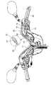
かかる課題を達成するために、請求項1に記載の発明は、車体フレームに対してユニットスイング式エンジンが上下動自在に連結され、該ユニットスイング式エンジンに外気導入ダクトが接続され、該外気導入ダクトの吸気口から外気を吸入してエンジンを冷却するスクータ型車両のエンジン冷却構造において、前記外気導入ダクトは、前記ユニットスイング式エンジンから前方に向けて延長されて前記車体フレームに固定されると共に、該固定部位と前記ユニットスイング式エンジンとの間に蛇腹状の可撓性部が設けられ、更に、前記吸気口を、前記車体フレームの車両前後方向中央部に配置されるフートレストボードの車幅方向中央部にて上方に突出するトンネル部内に開口させる一方、前記可撓性部を、側面視において、前記ユニットスイング式エンジンを前記車体フレームに対して上下動自在に連結する軸の上方の位置であって、かつ前記車体フレームの一部と交差する位置に配置し、前記外気導入ダクトは、平面視において、前記ユニットスイング式エンジンから前方に向けて延長されてから前記可撓性部において車幅方向中央部に向かって湾曲していることを特徴とする。
請求項2に記載の発明は、請求項1に記載の構成に加え、前記ユニットスイング式エンジンを前記車体フレームに対して上下動自在に連結する軸を前記ユニットスイング式エンジンの前側下部に設けたスクータ型車両のエンジン冷却構造としたことを特徴とする。
請求項3に記載の発明は、請求項1に記載の構成に加え、前記外気導入ダクトは、前記可撓性部と前記吸気口との間に剛体部を備え、この剛体部を、前記フートレストボードのトンネル部内において上方に延設し、前記吸気口を、前記トンネル部の内部の車幅方向中央部上面に近接して対向するように開口させたスクータ型車両のエンジン冷却構造としたことを特徴とする。
【0008】
【発明の実施の形態】
以下、この発明の実施の形態について説明する。
【0009】
図1乃至図49には、この発明の実施の形態を示す。この発明の実施の形態では、発明箇所を含むスクータ型車両の全体について説明する。
【0010】
この実施の形態のスクータ型車両は、概略的には、車体フレーム1(以下「フレーム1」という)にスイングユニット式エンジン2が上下方向に揺動自在に連結されると共に、フレーム1の前部には前輪3が配設され、前記スイングユニット式エンジン2側に後輪4が配設されている。
【0011】
そして、この骨格であるフレーム1は、図10及び図11等に示すように、複数のパイプが連結されて構成され、このフレーム1の周囲に複数のカバーが装着されている。
【0012】
具体的には、まず、図6に示すように、フレーム1の車両前後方向の中央部に配置される「中央カバー」としてのフートレストボード6を基準として、このフートレストボード6の前側に、「他のカバー」としてのレッグシールド7,フロントパネル8及びフロントモール9が順次取り付けられ、又、フートレストボード6の後側に、「他のカバー」としてのサイドカバー11及びタンデムフートステップ12が取り付けられ、更に、フートレストボード6の横側に、サイドモール13が取り付けられている。そして、これらの下側には下部カバー58が配設されている。
【0013】
そのフートレストボード6は、図12に示すように、車両後方から見て左側に基準ボルト孔6aが、又、この基準ボルト孔6aと中心線を挟んで反対側に車幅方向に長い長孔6bが、更に、これら基準ボルト孔6a及び長孔6bの前側には、それぞれバカ孔6c,6dが形成されている。
【0014】
そして、その基準ボルト孔6aに、図3及び図10等に示すステー1aから突設された図示省略のボルトが挿通されてネジ止めされ、この基準ボルト孔6aとそのネジとは略同じ径に設定されているため、フートレストボード6の左右前後方向の位置決めがなされる。但し、基準ボルト孔6aを中心とする回転方向の位置決めはなされない。
【0015】
同様に、上記長孔6b及び遊挿孔6c,6dに各ステー1b,1c,1dから図示省略のボルトが挿通されてネジ止めされている。その長孔6bにボルトがネジ止めされることにより、上記回転方向の位置決めが成される。
【0016】
このようにしてフートレストボード6がフレーム1に対して所定位置に取り付けられる。
【0017】
次いで、このフートレストボード6を基準として、このフートレストボード6の前端縁との位置合わせをしてレッグシールド7をフレーム1にネジ止めして固定する。この場合のレッグシールド7の取付けは、図示していないが、遊挿孔にネジを挿通することで、多少の位置ズレが生じた場合でも、この位置ズレを吸収するようにしている。
【0018】
そして、フレーム1に固定されたブラケット1eにステー15を動く状態に仮締めすると共に、フロントパネル8を仮置きし、このフロントパネル8とヘッドライト16とをステー15に仮締めする。その後、このヘッドライト16をフロントパネル8にスクリュー止めすると共に、フロントパネル8をレッグシールド7に、このレッグシールド7を基準としてスクリュー止めする(図13参照)。
【0019】
次いで、ステー15とヘッドライト16とフロントパネル8とを本締めし、その後、ステー15とブラケット1eとを本締めする。
【0020】
一方、フートレストボード6の後ろ側のサイドカバー11も、そのフートレストボード6を基準として位置合わせした状態で、図示省略の遊挿孔等を介して位置ズレを吸収して配設する。
【0021】
このようにフートレストボード6を基準として前側又は後側に順次他のカバーを組み付けて行くため、前端部又は後端部を基準に組み付けて行く場合より、前端部又は後端部での誤差が少なく、組立精度が向上することとなる。
【0022】
一方、フレーム1の前端部に形成されたヘッドパイプ1fには、ハンドル18が回転自在に支持され、このハンドル18がハンドルカバー19で覆われている。このハンドルカバー19は、ハンドル18に沿って略V字状に形成され、このハンドルカバー19内に各種ハーネス21及び後輪ディスクブレーキ用のブレーキワイヤ22が配索されている(図14参照)。
【0023】
このブレーキワイヤ22は、剛性を有する曲りパイプ23及び樹脂製のパイプ24内に挿通されている。その曲りパイプ23は、ブレーキハンドル25の近傍に配設されると共に、この曲りパイプ23の端部に樹脂製のパイプ24の端部が嵌合されて接続されている。
【0024】
そのブレーキワイヤ22がブレーキハンドル25の操作により引かれることで、このワイヤ22がパイプ23,24内を相対移動してディスクブレーキのブレーキ操作がなされるようになっている。
【0025】
そして、このようにブレーキワイヤ22を剛性を有する曲りパイプ23に挿通することにより、V字状とされて曲がりの大きいハンドルカバー19内であっても、そのブレーキワイヤ22を配策することができるため、ハンドルカバー19の外側にブレーキワイヤ22等が露出することなく、外観品質を確保することが出来る。
【0026】
また、そのハンドルカバー19をV字状に形成することにより、図15に示すように、運転者によるスピードメータ等の計器類26の視認性を確保しつつ、外観品質も向上させることが出来る。
【0027】
一方、その計器類26の前側には、図15,図16及び図17に示すように、メータバイザー28が立設されており、このメータバイザー28の前側には、一定の間隙cを持って、このメータバイザー28より大型のスクリーン29が配設されている。
【0028】
そのメータバイザー28は、図17等に示すように、第1メータバイザー30と第2メータバイザー31とから構成され、この第1メータバイザー30に前記計器類26が配設され、この第1,第2メータバイザー30,31がネジ32止めされることにより組み付けられている。
【0029】
そして、この第2メータバイザー30の外表面の車幅方向中央部に上下方向に沿う凹所31aが形成されている。
【0030】
また、スクリーン29は、図16に示すように、下端部29a側が第2メータバイザー31にネジ止めされて取り付けられ、水平断面が第2メータバイザー31と略同心円上で湾曲して形成されている。
【0031】
そして、計器類26が取り付けられたメータバイザー31及びスクリーン29をサブ組みして、フレーム1やレッグシールド7等に着脱するようにしている。このようにすれば、計器類26等の着脱作業性を向上させることが出来、スピードメータのバルブ交換等を簡単に行うことができる。
【0032】
また、第2メータバイザー30には、間隙c側に凹所31aが形成されているため、この部分では、スクリーン29との間隙cが広くなり、手を差し込んで、スクリーン29の裏側の掃除がし易くなると共に、この凹所31aは、車幅方向中央部に、つまり、間隙cの一番深い部分に形成されているため、この部分に手を差し込めば、その凹所31aの両側に対応する部分のスクリーン29裏面側の掃除も簡単に行うこともできる。
【0033】
また、このスクータ型車両のフロント側には、荷物を吊り下げる荷下げフック35がフロントトランク36の上側に配設されている(図18,図19及び図20参照)。
【0034】
すなわち、このフロントトランク36は、荷物収納室を有するトランク本体36aに開閉蓋36bが配設され、この開閉蓋36bは、下端部36cがヒンジを介して回動自在に取り付けられ、この開閉蓋36bにより、トランク本体36aが開閉されるようになっており、このトランク本体36aの開口周縁部にはシール部材36eが環状に配設され、開閉蓋36bの周縁部が当接することによりシールが行われるようになっている。しかも、この開閉蓋36bの上部には、ロック装置36dが配設されている。
【0035】
そして、前記荷下げフック35は、その開閉蓋36bのロック装置36dの上側に配設されている。この荷下げフック35は、車体側に固定される取付け部35aと、この取付け部35aから後方に延長された鉤形状のフック部35bとを有している。
【0036】
その取付け部35aは、レッグシールド7に形成された取付け凹部7aに挿入され、ボルト37・ナット38により、フレーム1に固定されたステー1gにそのレッグシールド7と共に共締めされている。
【0037】
このフック部35bの荷物引っ掛け位置Pは、開閉蓋36bの一般面より後方に突出しているため、このフック部35bに荷物を吊り下げた場合には、この荷物の荷重が直接開閉蓋36bに作用することが無く、この開閉蓋36bとトランク本体36aとの間のシール部材36e等を損傷させることが少ない。
【0038】
また、この荷下げフック35は、ロック装置36dの上側近傍に配置されているため、このロック装置36d配設部廻りのレッグシールド7は剛性が高いことから、荷下げフック35の支持強度も確保することが出来る。しかも、ここでは、フレーム1のステー1gに取り付けられているため、一層支持強度が向上することとなる。
【0039】
さらに、レッグシールド7には、荷下げフック35の配設部分に平面形状の面取り部7bが形成されているため、荷下げフック35を後方にそれ程突出させることなく、この荷物の紐を引っかけるスペースを確保することが出来る。
【0040】
さらに、図18中、この荷下げフック35の右横には、メインスイッチ40が、フレーム1のヘッドパイプ1fにブラケット1hを介して取り付けられている。そして、このメインスイッチ40の上端部40aが、レッグシールド7に形成された開口7cから露出しており、そのメインスイッチ上端部40aの鍵穴にキーが挿入されて施錠・開錠できるようになっている。
【0041】
そして、そのレッグシールド7上面部の開口7aの周縁部7dが下方に凹まされることにより、水がメインスイッチ40内に浸入し難いようにしている。
【0042】
一方、前記フロントパネル8の前面の下部両側に、下側が開放された切欠き部8aが形成され、この切欠き部8aにフロントフラッシャーランプ42が配設されている。
【0043】
すなわち、フロントフラッシャーランプ24は、図6中a,b,cの3ヶ所でフロントパネル8に取り付けられている。それら各位置a,b,cでの取付は、位置aで代表される図22に示すように、その切欠き部8aの周縁部に、取付ボス部8bが後方に向けて突設される一方、前記フロントフラッシャーランプ42のランプ本体42aには、取付け片42bが突設されている。そして、これら取付け片42bが前記取付ボス部8bにネジ43止めされることにより、フロントフラッシャーランプ42がその切欠き部8aに嵌合されるようにして取り付けられている。
【0044】
このようにすれば、フロントフラッシャーランプ42がフロントパネル8の前面の最下端部に位置しているため、図21中矢印に示すように、このフロントフラッシャーランプ42の裏側に手を挿入し易くバルブ42c交換の作業性が良好である。
【0045】
また、そのフロントフラッシャーランプ42を切欠き部8aに取り付けることにより、切欠き部8aの下側が開放されていても、このフロントフラッシャーランプ42取付部分の面剛性を確保できる。
【0046】
さらに、切欠き部8aの下側が開放されており、ここにフロントフラッシャーランプ42を配設することにより、下方への照射範囲を拡大することが出来る。
【0047】
前記フートレストボード6は、図5及び図6に示すように、車幅方向中央部に上方に突出するトンネル部6eが形成されると共に、このトンネル部6eの両側に足載せ部6fが形成されている。
【0048】
この足載せ部6fは、図6に示すように、後ろ上がりに形成され、この後端部にメンテ開口6gが形成され、このメンテ開口6gにタンデムフートステップ12が配設されている。このタンデムフートステップ12には、一部に凹所12aが形成され、フレーム1に図6中2ヶ所でネジ12bにて取り付けられている。
【0049】
このタンデムフートステップ12を外すことにより、そのメンテ開口6gからエンジン2側のメンテナンス(プラグ交換等)を行うことができ、このタンデムフートステップ12をメンテリッドと兼用できることとなる。
【0050】
また、このタンデムフートステップ12は、凹所12aが形成されることにより、この凹所12aに図6中二点鎖線に示すようにタンデムライダーの足の踵を位置させるようにすれば、足首を無理に延ばす必要なく、楽な状態で、足を置くことが出来る。
【0051】
しかも、この凹所12aの上側のサイドカバー11には、側方に膨らむ膨出部11aが形成されているが、この凹所12aを形成してこの凹諸12a底面の位置を下げることにより、その膨出部11aの下側に、この膨出部11aを回避してその凹所12aの足載せ面を位置させることが出来るため、タンデム乗員の乗り込み時用スペースを確保することができる。
【0052】
さらに、図23に示すように、サイドカバー11の後面部11bの内側には、テールランプ47が配設され、このサイドカバー後面部11bに上下一対のランプ開口11cが配設され、これらランプ開口11cからテールランプ47が臨んでいる。このテールランプ47は、一枚のレンズ47aの裏側にバルブ47bが配設され、この一枚のレンズ47aが、前記両ランプ開口11cに跨って外部に露出している。
【0053】
このように上下一対のランプ開口11cを設け、ここから一つのテールランプ47の異なる部分を露出させることで、外観上は、2つのテールランプ47が配設されているように見え、外観品質が向上することとなる。
【0054】
一方、図1等に示すように、前記スイングユニット式エンジン2には、前側下部に、ブラケット49が取り付けられ、軸50を介してフレーム1に対して上下動自在に取り付けられている。
【0055】
また、このエンジン2の後端部側には、リヤクッション51の下端部51aが回動自在に取り付けられ、このリヤクッション51の上端部51bがフレーム1に固定されたブラケット54に回動自在に支持されている。
【0056】
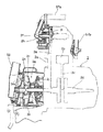
このスイングユニット式エンジン2は、図24に示すように、シリンダブロック2a内にピストン2bが配設され、このピストン2bがコネクティングロッド2cを介してクランクシャフト2dに連結されている。そして、このクランクシャフト2dにチェーン2eを介してウオータポンプ2fに接続されると共に、このクランクシャフト2dの端部には、Vベルト変速機2gが配設されている。
【0057】
そのウオータポンプ2fは、上記チェーン2eの伝達媒体を介してインペラ2hが回転されることにより、詳細は後述するラジエター56の供給ホース57aを介して冷却水がエンジン2内に流入されるようになっており、又、エンジン2内を循環した冷却水が戻りホース57bを介してラジエター56に戻るようになっている。
【0058】
また、Vベルト変速機2gは、クランクシャフト2dに源動側のプーリ2iが配設され、このプーリ2iのV字状の溝にVベルト2jが巻回されるようになっており、この溝の幅が変化することにより、Vベルト2jの位置が変化するようになっている。そして、このVベルト2jが図示省略の従動側のプーリに巻回され、後輪4に動力を伝達するようにしている。この従動側のプーリの溝の幅も変化するようになっている。
【0059】
そして、Vベルト変速機2gが配設された変速室2k内に外気を導入して冷却を行う外気導入ダクト52がエレメント2mを介して接続されている。
【0060】
この外気導入ダクト52は、前記ユニットスイング式エンジン2から前方に向けて延長され、ゴム製の可撓性部52aと、合成樹脂製の剛体部52bとを有している。この可撓性部52aは、前側の略半分が蛇腹状に形成され、後端部がベルト室(エンジン2)に接続される一方、前端部に、剛体部52bの後端部が接続されている。そして、この剛体部52bは、後端部近傍においてフレーム1にベルト53にて固定され、この固定箇所より前側において上方に延長されて、上端部がフートレストボードトンネル部6e内に挿入されてトンネル部6eの車幅方向中央部の上面に対向した位置で、その外気導入ダクト52の吸気口52cが開口して上方を向いている。
【0061】
このようにエンジン2はスイングユニット式であり、フレーム1に対して上下方向に揺動するため、その外気導入ダクト52の可撓性部52aで、スイングユニット式エンジン2とフレーム1との相対移動を吸収するようにしている。
【0062】
また、この外気導入ダクト52の吸気口52cが、トンネル部6e内の高い位置に設定され、しかも、外気導入ダクト52の吸気口52cは、トンネル部6e内で開口しているため、各車輪3,4により跳ね上げられた泥やエンジン2の熱気が、その吸気口52cから吸入されることが無く、清浄で冷えた外気をその変速室2k内に供給できて冷却性を確保することが出来る。この変速室2k内では、プーリ2iに形成されたフィン2nにより、その外気が後方に向けて送風される。
【0063】
ところで、フレーム1をダクトとして利用しているものも見受けられるが、径が細いため外気の単位時間当たりの流入量をそれ程大きく出来ず、冷却性を確保できない虞があり、径を大きくすると、車体重量の増加を招くこととなる。
【0064】
これに対して、フレーム1とは別に外気導入ダクト52を設けることにより、それ程、重量増加を招かずに、径を大きくできて冷却性能を確保できる。
【0065】
また、図25,図26及び図27に示すように、前記両リヤクッション51には、イニシャル調整を行う調整部材51cが配設されており、これら内の、マフラ55と後輪4との間に配設された一方のリヤクッション51の調整部材51cには、斜め下方に突出する操作パイプ51dが溶接されて斜め下方に向けて突設され、この操作パイプ51dを図示省略の車載ツールで操作して、調整部材51cを回転させることにより、イニシャル調整が可能となる。
【0066】
このように操作パイプ51dを溶接してマフラ55より下方に突設することにより、リヤクッション51がマフラ55と後輪4との間に配設されている場合でも、マフラ55が邪魔になることなく、イニシャル調整を簡単に行うことができる。
【0067】
図28中符号56はラジエターで、前記供給ホース57a及び戻りホース57bを介して前記のように水平で横置きに配設されたエンジン2に接続されている。
【0068】
そのラジエター56は、レッグシールド7のトンネル部7e内で、且つ、フレーム1のヘッドパイプ1fから斜め下方に延びる左右パイプ1iの間に配設されている(図30等参照)。
【0069】
このラジエター56は、上下にタンク部56a,56bが設けられると共に、これら両タンク部56a,56bがフィン部56cにより連結されている。このフィン部56cの間を走向風が通過することにより、このフィン部56c内を流れる冷却水が熱交換されて冷却されることとなる。そして、その下タンク部56aには、車両後方から見て車体右側に供給ホース57aが接続され、エンジン2まで延長され、又、エンジン2には、戻りホース57bが接続され、前方に延長されて上タンク部56bの車両後方から見て車体右側に接続されている。この戻りホース57bは、トンネル部7e,6e内に挿通されている。
【0070】
このように上下にタンク部56a,56bを配設することにより、ラジエター56の左右の幅を狭くできるため、足載せスペースを確保しつつ左右の車体幅を短くできる。
【0071】
また、戻りホース57bをトンネル部7e,6e内に配策することにより、戻りホース57bの配索に苦慮することがないと共に、トンネル部7e,6eで戻りホース57bを保護することが出来る。
【0072】
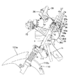
前記ラジエター56は、図31に示すように、車体の下方を覆う下部カバー58上に少し前傾した状態で配設されており、このラジエター56の後方にはラジエターガード59が配設されている。
【0073】
その下部カバー58は、前端部が上方に立ち上げられてラジエター56の前側にルーバ部58bが形成され、このルーバ部58bから走向風をラジエター56に導くようにしている。
【0074】
また、この下部カバー58には、ラジエター56の後方位置に冷却風排出口58aが形成され、更に、この下部カバー58の後端部58cが図6に示すように後方に向けてタンデムフートステップ12近傍まで延長されている。
【0075】
この下部カバー58は従来のインナーパネルとアンダーカバーとが一体に形成されたものに相当する。
【0076】
さらに、前記ラジエターガード59は、水平断面がコ字状を呈し、ラジエター56の側部に位置して車両前後方向に沿う一対の側壁59cと、この両側壁59cを連結する後壁59dとを有している。
【0077】
このラジエターガード59は、下端部59aが、下部カバー58の冷却風排出口58aに挿入される一方、上端部59bが、ラジエター56の上側を覆うようになっている。
【0078】
これにより、ルーバ部58bから導入された冷却風は、そのラジエター56を通過して熱交換された後、この温風がラジエターガード59に案内されて、下部カバー58の冷却風排出口58aから下方に排出されることとなる。
【0079】
なお、このラジエターガード59には、図1等に示すように、キャニスタ60が取り付けられている。
【0080】
一方、図9中符号64は、二人乗り用のシートで、このシート64の前側下部には燃料タンク65が、又、この燃料タンク65の後ろ側には収納ボックス66が配設されている。
【0081】
そして、その燃料タンク65と収納ボックス65との間には、図5,図6,図32及び図33に示すように、バッテリーボックス68が配設されている。このバッテリーボックス68は、「外装カバー」としてのサイドカバー11に一体成形され、この中にバッテリー69が収納できるようになっていると共に、蓋70で開閉できるようになっている。
【0082】
このように、バッテリーボックス68をサイドカバー11に一体成形することにより、部品点数が削減されると共に、スペースの有効活用が図られることとなる。
【0083】
特に、バッテリーボックス68が大型化すると、フートレストボード6の下側に配置するのはスペース的に難しくなり、又、車両フロント部側に配置した場合には、エンジン2まで長いハーネスを配索しなければならない。
【0084】
してみれば、エンジン2に近く、スペースを確保できる場所として、燃料タンク65と収納ボックス66との間が最適である。
【0085】
一方、燃料タンク65は、図34及び図35に示すように、フレーム1に支持され、上部の前端部に給油口65aが配設されている。そして、この燃料タンク65の側面部に、フューエルポンプ72が取り付けられ、燃料タンク65内の燃料をキャブレター73に供給するようにしている。
【0086】
詳しくは、この燃料タンク65の底面部65cには、ストレーナ74から延長されたホース75が接続され、このストレーナ74から延長されたホース75が前記フューエルポンプ72に接続されている。また、このフューエルポンプ72は、ホース76を介して前記キャブレター73に接続されると共に、負圧ホース77を介してインテークマニホールド78に接続されている。
【0087】
これによれば、インテークマニホールド78からの負圧を利用して、燃料タンク65からストレーナ74を介してフューエルポンプ72内に燃料を吸い込んだ後、このポンプ72から燃料を吐出させてホース76を介してキャブレター73に燃料を供給するようにしている。
【0088】
このようなものにあっては、燃料タンク65とキャブレター73の高さが近い位置に設定されているため、高低差を利用して、燃料タンク65からキャブレター73に良好に供給するのが難しいことから、フューエルポンプ72を用いて燃料タンク65内の燃料をキャブレター73側に強制的に送るようにしている。
【0089】
そして、この実施の形態のように、フューエルポンプ72を用いたものにおいて、このフューエルポンプ72の高さをキャブレター73の高さより高くすると共に、負圧ホース77を短くすることにより、性能の安定化を図ることができる。
【0090】
さらに、そのフューエルポンプ72は燃料タンク65の側面部65bに取り付けられているため、燃料タンク65の脱着時に、この燃料タンク65と共に脱着でき、サブアッセンブリが可能となる。
【0091】
前記収納ボックス66は、ヘルメット等が収納される大きさを有し、フレーム1に支持され、上部開口66aが前記シート64により開閉されるようになっている。
【0092】
そして、この収納ボックス66の側方には、図1及び図9に示すように、フレーム1の一部に上方に突出するようにスタンディングハンドル81が固定されて配設され、この部分における収納ボックス66,シート64及びサイドカバー11の断面構造は、図36に示すようになっている。
【0093】
すなわち、収納ボックス66の側壁66bには、上端部にシール面部66cが形成され、このシール面部66cの内側に堰部66dが、このシール面部66cの一般面より上方に突出されて形成されている。そして、このシール面部66cにシート64側に取り付けられたシール部材82が当接してシールされるようになっている。
【0094】
また、その収納ボックス66のシール面部66cの外側には、一段下がった位置に、水平面部66eが形成され、この水平面部66eの車外側端部が斜め上方に延びる傾斜片66fが形成されている。これら水平面部66e及び傾斜片66f等の「壁部」により、凹所66gが形成され、この凹所66gに、シート64の側縁部64aが挿入されている。
【0095】
さらに、収納ボックス側壁66bに形成された固定部66hに、サイドカバー11から延長された取付片11iがビス止めされる一方、このサイドカバー11には、前記スタンディングハンドル81に対応した部位に上方に膨らんで、このハンドル81を覆う被覆部11dが形成され、この被覆部11dの上端部11eが、前記収納ボックス傾斜片66fの上端フランジ部66i上に重なって連続するように配置されている。
【0096】
乗員は、このサイドカバー11に形成された開口11fから手を挿入してそのスタンディングハンドル81を持って車両を起き上がらせるようにすることができる。このサイドカバー11は車体中心を中心として左右に2分割されている。
【0097】
このようにシート側縁部64aを凹所66gに挿入すると共に、サイドカバー11の上端部11eが収納ボックス傾斜片66fの上端フランジ部66i上に重なるようにすれば、シート側縁部64aとサイドカバー11との連続性が得られ、外観品質が確保されることとなる。
【0098】
また、シール面部66cの内側に、上方に突出する堰部66dを形成することにより、単に平坦なシール面部66cにシール部材82を当接させてシールするものと比較すると、収納ボックス66内への水の浸入をより確実に防止することが出来る。
【0099】
さらに、シート64等から凹所66gに流れ落ちた水は、凹所66gが前下がりとなっているため、車両前方に向かって流れて排水され、収納ボックス66内への水の侵入を防止することが出来る。
【0100】
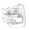
さらにまた、図2に示すように、その収納ボックス66の側壁66bには、AISクリーナ87が取り付けられる一方、このAISクリーナ87が接続されたAIS88が、後輪4を縣架するリヤアーム90に取り付けられている。
【0101】
そのAIS88は、排気ガスに外部から二次空気を導入するためのもので、エンジン2の負圧を利用して外部から空気を吸入し、この空気を排気マニホールド89の出口付近に供給することで酸化を促進して触媒をより活性化させるようにしている。
【0102】
また、AISクリーナ87は、その吸気の途中に設けられ、塵や水等が吸入されるのを阻止している。このAISクリーナ87には、パイプ87aが接続され、このパイプ87aの先端部がフレーム1に挿入され、ここから吸入した空気をAISクリーナ87で清浄化した後、パイプ87aを通して排気マニホールド89に供給するようにしている。
【0103】
このAISクリーナ87は、一端部がフレーム1に固定されたブラケット91に取り付けられる一方、他端部が収納ボックス66の側面部に取り付けられている。
【0104】
さらに、図9に示すように、前記収納ボックス側壁66bには、板金84が配置され、この板金84にシートダンパ85の後端部85aがボルト・ナット等により取り付けられ、このシートダンパ85の前端部85bが、前記シート64に取り付けられている。このシートダンパ85は、前記バッテリーボックス68の側方を通って配策され、図32に示すように、サイドカバー11の燃料タンク65を覆う部分にダンパ用開口11hが形成され、シート64を開いたときには、その開口11hが逃げとなってシートダンパ85が上方に回動するようになっている。
【0105】
そして、シート64を開いた状態では、ダンパ用開口11hを介して、図32等に示すように、キャブレター73のパイロットスクリュー73aが露出するため、このパイロットスクリュー73aの調整を簡単に行うことができる。
【0106】
前記シート64は、図9に示すように、シート芯材64b,クッション材64c及び表皮64dが積層されて構成され、前端部64eがヒンジ93を介してフレーム1側に回動自在に取り付けられている。
【0107】
そのシート芯材64bには、車両前後方向の略中央部から下方に向けて水平断面がH型を呈するシート側荷重受け部64fが突設される一方、前記スタンディングハンドル81の途中に支持座94が内側に向けて固定されている。そして、この支持座94に、サイドカバー11の凹部底面部11gがネジ95止めされる一方、この底面部11g上に前記シート側荷重受け部64fが当接されている。
【0108】
また、図2及び図9に示すように、前記シート64の後端部に対応する位置のフレーム1側には、シート64の後端部をロックするシートロック装置97が配設され、このシートロック装置97がシートロックワイヤ98を介して前記メインスイッチ40に連結されている。
【0109】
そして、メインスイッチ40をキー操作してロック解除位置まで作動させると、シートロックワイヤ98が引かれて遠隔操作されることにより、シートロック装置97がロック解除されるようになっている。
【0110】
このシートロックワイヤ98は、前端部98aから後方に向けてトンネル部6e,7e内に挿通された後、断面U字状のプロテクタ99内に挿通され、更に、このプロテクタ99の後端部99aからフレーム1内に挿通され、このフレーム1の後端部から引き出されてシートロック装置97に連結されている。
【0111】
このように断面U字状のプロテクタ99やパイプ形状のフレーム1内に、シートロックワイヤ98を挿入して保護することにより、外部からの不正開錠入力により、このシートロックワイヤ98が引かれることを防止でき、防盗性を確保することができる。
【0112】
さらに、前記シート64の後方には、図9,図37,図38等に示すように、タンデムハンドル101が配設され、このタンデムハンドル101等にキャリヤ102とバックレスト103とが取り付けられている。
【0113】
このタンデムハンドル101は、図37に示すように、前側脚部101aがボルト101bによりフレーム1に固定され、後側取付け部101cがボルト101dによりフレーム1に取り付けられている。
【0114】
一方、キャリヤ102は、下側先端部のフレーム取付け部102aが図38に示すようにボルト102cにてフレーム1に取り付けられ、このボルト102cが前記タンデムハンドル101の後側取付け部101cにて覆われている。また、このキャリヤ102は、上側先端部のハンドル取付け部102bが図9に示すようにボルト102dにてタンデムハンドル101に取り付けられている。
【0115】
さらに、前記バックレスト103は、図9に示すように、タンデムハンドル101の後部上にボルト103aにて固定されている。
【0116】
さらにまた、図39及び図40に示すように、前記シート64の前端部側の裏面には、ヘルメットを吊り下げるヘルメットハンガー105が配設されている。
【0117】
このヘルメットハンガー105は、ワイヤ式で、一端部105aがシート64裏面に取り付けられ、他端部にリング部105bが設けられ、このリング部105bがシート64裏面に設けられたフック棒106に係脱されるようになっている。また、シート64の裏面には、折返し部材109が配置されて、この折返し部材109にヘルメットハンガー105の途中が掛けられて折り返されている。
【0118】
一方、燃料タンク65側には、前記フック棒106に対応する位置に突起部107が上方に向けて突設されている。
【0119】
このヘルメットハンガー105の使用方法は、シート64を開いた状態で、ヘルメットのリング108にそのハンガー105を挿通し、次いで、このハンガー105のリング部105bをシート64裏面のフック棒106に引っかける。そして、シート64を閉じることにより、そのフック棒106が、燃料タンク65側の突起部107に挿入された状態で、そのリング部105bのフック棒106からの外れが防止されることとなる。
【0120】
ところで、前記前輪3の上側を覆うフロントフェンダ110は、図20に示すように、アンダーブラケット111より前側の前方部110aが上方に突出し、このアンダーブラケット111の下側から後方の後方部110bが一段下がって形成されている。
【0121】
このようにすれば、このフロントフェンダ110が前輪3と一体となって上下動しても、フロントフェンダ110の後方部110bとアンダーブラケット111との間に間隙Hが確保されているため、フロントフェンダ110とアンダーブラケット111とが干渉することがないと同時に、一段高くなったフロントフェンダ前方部110aで、アンダーブラケット111との間隙が前方から見えないようになっていることから、外観品質を確保出来ることとなる。
【0122】
一方、図1乃至図3,図41乃至図44に示すように、後輪4側に設けられたリヤフェンダ113は、後輪4の上側を覆うリヤフェンダ本体部113aと、このリヤフェンダ本体部113aの前端部の右角部分から延長された覆い部113bとが形成されている。この覆い部113bにより、前記AISクリーナ87が覆われるようになっている。
【0123】
そして、この覆い部113bとリヤフェンダ本体部113aとの境部分に、図43に示すように、計2つの水抜き孔113cが形成されている。
【0124】
このように水抜き孔113cを形成することにより、この水抜き孔113cからリヤフェンダ113上の水を排水することができ、エアクリーナ115への防水が行われることとなる。
【0125】
すなわち、後輪4により巻き上げられた水等で、リヤフェンダ本体部113a上の水は、車体中心線の左側においては、エアクリーナ115自体に遮られて、このエアクリーナ115の前面側に配置された吸気口115aから侵入することはない。また、後輪4により巻き上げられた水等で、リヤフェンダ本体部113a上の水は、車体中心線の右側においては、水抜き孔113cから排水されることより、ここより前側に流れて行くことが無く、そのエアクリーナ115の前面側に配置された吸気口115aからの水の浸入が防止されることとなる。
【0126】
また、図8及び図45に示すように、そのエアクリーナ115の吸気口115aは、斜め外側を向いており、この吸気口115aの周囲にはボックス部116が配置され、このボックス部116の開口116aが側方を向いていると共に、この開口116a周縁部に外側に向けて開口116a内への水の浸入を防止するフランジ部116bが形成されている。このフランジ部116bの上部側には、切欠き部116cが形成され、ここにスポンジ119が配設されている。
【0127】
さらに吸気口115aの上側には、車両前後方向に延びる第1防水フラップ117がベルト117aにてフレーム1に取り付けられて垂下され、又、その吸気口115aの前側には、車幅方向に沿う第2防水フラップ118が孔118aに挿通されたベルト118bにて取り付けられて配設されている。この両防水フラップ117,118はゴム製で一体成形されている。
【0128】
この第1防水フラップ117により、上方からの水が吸気口115aに侵入しないようにすると共に、第2防水フラップ118により、車両前方からの水が吸気口115aに浸入しないようにしている。
【0129】
また、ボックス部116上を流れてきた水は、スポンジ119で吸収されることにより、開口116aからエアクリーナ115の吸気口115aに浸入されるのを防止できる。このようにスポンジ119を設ければ、ここに水が衝突した場合でも跳ね上がりを防止できるため、単にフランジ116bが形成されているものと比較すると、水の浸入を有効に防止できる。また、サイドモール13には、第2防水フラップ118の裏面近傍にリブ13gが形成されているため、この第2防水フラップ118の前側から後ろ側に水が回り込むのを防止できる。
【0130】
一方、図46中符号120はリカバリータンクで、このリカバリータンク120は、フートレストボード6の下側に配設されている。詳しくは、そのリカバリータンク120は、タンク本体120aがキャップ120bにより開閉自在に設けられる一方、このキャップ120bが、フートレストボード6に形成されたひょうたん形のタンク開口6hから上方に臨んでいる。そして、このタンク開口6hがカバー121で開閉されるようになっている。
【0131】
このカバー121には、一対のフック片121aが突設される一方、これらフック片121aと反対側の辺には弾性変形可能な係止片121bが形成されている。そして、それら一対のフック片121aは、前記タンク開口6hの周縁部の裏面側に係止されると共に、その係止片121bが当該周縁部に係脱されるようになっている。
【0132】
また、前記キャップ120bには舌片120cが形成され、この舌片120cを持ってキャップ120bを外すことにより吸水できるようになっている。
【0133】
このリカバリータンク120に冷却水を吸水するときには、マット123を外した後、カバー121の係止片121bを操作して係止状態を解除して外し、更に、舌片120cをもってキャップ120bを外すようにしている。このようにキャップ120bを外すときには、タンク開口6hのひょうたん形の頭の部分に指を挿入して舌片120cを摘むことが出来、その頭の部分を指の挿入スペースにできる。
【0134】
前記サイドモール13とフートレストボード6との合わせ部は、図5,図47,図48及び図49に示すようになっている。すなわち、サイドモール13の上部には、略水平に延びる取付片13aが形成され、この取付片13aには、ボルト孔13bが形成されると共に、この取付片13aの更に先端には突起片13cが形成されている。そして、この取付片13aにフートレストボード6の断面コ字状の固定部6iがネジ13d止めされている。
【0135】
また、このサイドモール13の上端部には、マット123の端縁部が載置される載置片13eが形成されると共に、この載置片13eには段差部13fが形成され、この段差部13fにマット123の端縁部が嵌合されるようになっている。これにより、マット123の位置決めが成されると共に、このマット123の端縁部の浮きを防止することが出来る。
【0136】
さらに、そのサイドモール13の取付片13aには、更に前方に延びる突起片13cが形成されているため、このサイドモール13の仮止め時に、その取付片13aを、フートレストボード6の断面コ字状の固定部6iの内側に挿入した状態で、そのサイドモール13が外側に倒れようとすると、その突起片13cがフートレストボード6の裏面に当接することから、その倒れを防止することが出来る。
【0137】
【発明の効果】
以上説明してきたように、請求項に記載された発明によれば、外気導入ダクトの吸気口はシートの前側のトンネル部内に開口しているため、各車輪により跳ね上げられた泥や、エンジンの熱気が、その吸気口から吸入されることが少なく、清浄で冷えた外気をエンジン内に供給できて冷却性を確保することが出来る。
【0138】
また、エンジンはユニットスイング式であり、フレームに対して上下方向に揺動するため、その外気導入ダクトの可撓性部で、エンジンとフレームとの相対移動を吸収することができる、という実用上有益な効果を発揮する。
【図面の簡単な説明】
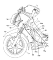
【図1】この発明の実施の形態に係るスクータ型車両の全体概略を示す側面図である。
【図2】同実施の形態に係るスクータ型車両の全体概略を示す側面図である。
【図3】同実施の形態に係るスクータ型車両の全体概略を示す平面図である。
【図4】同実施の形態に係るスクータ型車両の全体概略を示す平面図である。
【図5】同実施の形態に係るシートを外した状態のスクータ型車両の平面図である。
【図6】同実施の形態に係るカバー類を組み合わせた状態の側面図である。
【図7】同実施の形態に係るカバー類を組み合わせた状態の正面図である。
【図8】同実施の形態に係るカバー類を外した状態の側面図である。
【図9】同実施の形態に係るシート等を示す一部を破断した側面図である。
【図10】同実施の形態に係るフレームを示す平面図である。
【図11】同実施の形態に係るフレームを示す側面図である。
【図12】同実施の形態に係るフートレストボードの一部を示す平面図である。
【図13】同実施の形態に係る車両のフロント部分の分解斜視図である。
【図14】同実施の形態に係るハンドルカバー内を正面から見た図である。
【図15】同実施の形態に係る計器類を運転者から見た図である。
【図16】同実施の形態に係るスクリーンやメータバイザー等を側方から見た図である。
【図17】同実施の形態に係る第1,第2メータバイザーを示す分解斜視図である。
【図18】同実施の形態に係るフロントトランクや荷下げフック等を示す図である。
【図19】同実施の形態に係るフロントトランクの開閉蓋の一部を破断した図である。
【図20】同実施の形態に係るフロントフェンダ等を示す側面図である。
【図21】同実施の形態に係る図7のA−A線に沿う断面図である。
【図22】同実施の形態に係る図6のBーB線に沿う断面図である。
【図23】同実施の形態に係るスクータ型車両を後方から見た図である。
【図24】同実施の形態に係るエンジンの一部を示す平面図である。
【図25】同実施の形態に係るリヤクッションとマフラを示す側面図である。
【図26】同実施の形態に係るリヤクッションとマフラを示す平面図である。
【図27】同実施の形態に係るリヤクッションの半断面図である。
【図28】同実施の形態に係るラジエター等の配索状態を示す側面図である。
【図29】同実施の形態に係るラジエター等の配索状態を示す平面図である。
【図30】同実施の形態に係る図28を矢印C方向から見た正面図である。
【図31】同実施の形態に係るスクータ型車両の前部の側面図である。
【図32】同実施の形態に係るバッテリーボックス部分の平面図である。
【図33】同実施の形態に係る図32のD−D線に沿う断面図である。
【図34】同実施の形態に係る燃料タンク配設部廻りの平面図である。
【図35】同実施の形態に係る燃料タンク配設部廻りの側面図である。
【図36】同実施の形態に係る図9のE−E線に沿う断面図である。
【図37】同実施の形態に係る図9のF−F線に沿う断面図である。
【図38】同実施の形態に係る図9のGーG線に沿う断面図である。
【図39】同実施の形態に係るヘルメットハンガーの概略を示す側面図である。
【図40】同実施の形態に係るヘルメットハンガーの概略を示す平面図である。
【図41】同実施の形態に係るリヤフェンダの側面図である。
【図42】同実施の形態に係るリヤフェンダの平面図である。
【図43】同実施の形態に係る図42のHーH線に沿う断面図である。
【図44】同実施の形態に係る図42を矢印I方向から見た図である。
【図45】同実施の形態に係る第2防水フラップ等を正面から見た図である。
【図46】同実施の形態に係る図4のJ−J線に沿う断面図である。
【図47】同実施の形態に係る図5のK−K線に沿う断面図である。
【図48】同実施の形態に係るサイドモールの平面図である。
【図49】同実施の形態に係る図48のL−L線に沿う断面図である。
【符号の説明】
1 フレーム
2 ユニットスイング式エンジン
6 フートレストボード
6e トンネル部
50 軸
52 外気導入ダクト
52a 可撓性部
52b 剛体部
52c 吸気口[0001]
BACKGROUND OF THE INVENTION
The present invention relates to an engine cooling structure for a scooter type vehicle that cools by introducing outside air to the engine side.
[0002]
[Prior art]
Conventionally, a V-belt transmission has been provided on the engine side of the scooter type vehicle, and the temperature in the belt chamber in which the V-belt transmission is provided is reduced by heat transfer from the engine and frictional heat of the V-belt. Becomes higher.
[0003]
For this reason, in a 50 cc class scooter type vehicle, vanes are attached to the pulley of the V-belt to agitate the belt chamber and suppress a local temperature rise in the belt chamber.
[0004]
However, when the engine displacement becomes large, this is not sufficient. Therefore, an outside air introduction duct is connected to the engine, and outside air is introduced into the belt chamber for cooling.
[0005]
[Problems to be solved by the invention]
However, in such a conventional apparatus, since outside air is introduced into the belt chamber through the outside air introduction duct, there is a possibility that dust and hot air may be introduced through the outside air introduction duct. . Further, since the engine is a unit swing type, and an external air introduction duct is connected to the engine, it is necessary to prevent adverse effects even if the engine moves up and down.
[0006]
Therefore, an object of the present invention is to provide an engine cooling structure for a scooter type vehicle that suppresses the introduction of dust and hot air and prevents adverse effects even when the engine moves up and down.
[0007]
[Means for Solving the Problems]
In order to achieve the above object, according to the first aspect of the present invention, a unit swing type engine is connected to a vehicle body frame so as to freely move up and down, and an outside air introduction duct is connected to the unit swing type engine. In the engine cooling structure of a scooter type vehicle that cools the engine by sucking outside air from the air intake of the duct, the outside air introducing duct is extended forward from the unit swing type engine and fixed to the vehicle body frame. A vehicle width of a footrest board in which a bellows-like flexible portion is provided between the fixed portion and the unit swing type engine, and the intake port is disposed at the vehicle longitudinal direction center portion of the body frame. while is opened in the tunnel portion protruding upward at direction central portion, the flexible portion in a side view, said unit A the queuing engine above the position of the shaft which vertically movably coupled to the body frame, and disposed at a position intersecting with a portion of the body frame, wherein the external air introducing duct, in a plan view, The vehicle is extended toward the front from the unit swing type engine, and is then curved toward the center in the vehicle width direction at the flexible portion .
According to a second aspect of the present invention, in addition to the configuration according to the first aspect, a shaft for connecting the unit swing type engine to the body frame so as to be movable up and down is provided at a lower part on the front side of the unit swing type engine. It has an engine cooling structure for a scooter type vehicle.
According to a third aspect of the present invention, in addition to the configuration of the first aspect, the outside air introduction duct includes a rigid body portion between the flexible portion and the intake port, and the rigid body portion is used as the footrest. A scooter-type vehicle engine cooling structure that extends upward in the tunnel portion of the board and has the intake port opened to be close to and opposed to the upper surface of the center portion in the vehicle width direction inside the tunnel portion. Features.
[0008]
DETAILED DESCRIPTION OF THE INVENTION
Embodiments of the present invention will be described below.
[0009]
1 to 49 show an embodiment of the present invention. In the embodiment of the present invention, the entire scooter type vehicle including the invention location will be described.
[0010]
The scooter-type vehicle according to this embodiment generally includes a swing
[0011]
The
[0012]
Specifically, as shown in FIG. 6, first, with reference to a
[0013]
As shown in FIG. 12, the
[0014]
A bolt (not shown) protruding from the
[0015]
Similarly, bolts (not shown) are inserted from the
[0016]
In this way, the
[0017]
Next, with the
[0018]
Then, the
[0019]
Next, the
[0020]
On the other hand, the
[0021]
Since the other covers are sequentially assembled on the front side or the rear side based on the
[0022]
On the other hand, a
[0023]
The
[0024]
When the
[0025]
And by inserting the
[0026]
Further, by forming the
[0027]
On the other hand, as shown in FIGS. 15, 16, and 17, a
[0028]
The
[0029]
And the recessed
[0030]
As shown in FIG. 16, the
[0031]
Then, the
[0032]
Moreover, since the
[0033]
In addition, on the front side of the scooter type vehicle, a
[0034]
That is, the
[0035]
The unloading
[0036]
The mounting
[0037]
Since the load hooking position P of the
[0038]
Further, since the unloading
[0039]
Furthermore, since the
[0040]
Further, in FIG. 18, on the right side of the unloading
[0041]
Then, the
[0042]
On the other hand, a
[0043]
That is, the
[0044]
In this way, since the
[0045]
Further, by attaching the
[0046]
Further, the lower side of the
[0047]
As shown in FIGS. 5 and 6, the
[0048]
As shown in FIG. 6, the
[0049]
By removing the
[0050]
In addition, the
[0051]
In addition, the
[0052]
Further, as shown in FIG. 23, a
[0053]
Thus, by providing a pair of upper and
[0054]
On the other hand, as shown in FIG. 1 and the like, a
[0055]
Further, a
[0056]
As shown in FIG. 24, the swing
[0057]
In the
[0058]
In the V-belt transmission 2g, a pulley 2i on the driving side is disposed on the
[0059]
An outside
[0060]
The outside
[0061]
Thus, the
[0062]
Further, the
[0063]
By the way, although the
[0064]
On the other hand, by providing the outside
[0065]
Further, as shown in FIGS. 25, 26 and 27, the
[0066]
By thus welding the
[0067]
In FIG. 28,
[0068]
The
[0069]
The
[0070]
By arranging the
[0071]
In addition, by arranging the
[0072]
As shown in FIG. 31, the
[0073]
The
[0074]
The
[0075]
The
[0076]
Further, the
[0077]
The
[0078]
As a result, the cooling air introduced from the
[0079]
Note that a
[0080]
On the other hand,
[0081]
A
[0082]
Thus, by integrally forming the
[0083]
In particular, when the
[0084]
As a result, the space between the
[0085]
On the other hand, as shown in FIGS. 34 and 35, the
[0086]
Specifically, a
[0087]
According to this, after the fuel is sucked into the
[0088]
In such a case, since the heights of the
[0089]
And in this embodiment using the
[0090]
Further, since the
[0091]
The
[0092]
As shown in FIGS. 1 and 9, a standing
[0093]
That is, the
[0094]
Further, on the outside of the
[0095]
Further, an attachment piece 11i extending from the
[0096]
The occupant can insert his hand through the
[0097]
If the seat
[0098]
Further, by forming a
[0099]
Furthermore, the water that has flowed down into the
[0100]
Furthermore, as shown in FIG. 2, an
[0101]
The
[0102]
Further, the
[0103]
The
[0104]
Further, as shown in FIG. 9, a
[0105]
When the
[0106]
As shown in FIG. 9, the
[0107]
The
[0108]
As shown in FIGS. 2 and 9, a
[0109]
When the
[0110]
The
[0111]
Thus, by inserting and protecting the
[0112]
Further, as shown in FIGS. 9, 37, 38 and the like, a
[0113]
As shown in FIG. 37, the tandem handle 101 has a
[0114]
On the other hand, in the
[0115]
Further, as shown in FIG. 9, the
[0116]
Further, as shown in FIGS. 39 and 40, a
[0117]
The
[0118]
On the other hand, on the
[0119]
The
[0120]
By the way, as shown in FIG. 20, the
[0121]
In this way, even if the
[0122]
On the other hand, as shown in FIGS. 1 to 3 and FIGS. 41 to 44, a
[0123]
As shown in FIG. 43, a total of two
[0124]
By forming the
[0125]
That is, the water on the rear fender
[0126]
8 and 45, the
[0127]
Further, a first
[0128]
The first
[0129]
Further, the water flowing on the
[0130]
On the other hand,
[0131]
The
[0132]
Further, the
[0133]
When the cooling water is absorbed into the
[0134]
The mating portion between the
[0135]
In addition, a mounting
[0136]
Further, since the mounting
[0137]
【The invention's effect】
As described above, according to the invention described in the claims, since the intake port of the outside air introduction duct is opened in the tunnel portion on the front side of the seat, the mud splashed by each wheel, the engine Hot air is hardly sucked from the intake port, and clean and cool outside air can be supplied into the engine to ensure cooling performance.
[0138]
In addition, since the engine is a unit swing type and swings in the vertical direction with respect to the frame, the flexible part of the outside air introduction duct can absorb the relative movement between the engine and the frame. Has a beneficial effect.
[Brief description of the drawings]
FIG. 1 is a side view showing an overall outline of a scooter type vehicle according to an embodiment of the present invention.
FIG. 2 is a side view showing an overall outline of the scooter type vehicle according to the embodiment.
FIG. 3 is a plan view showing an overall outline of the scooter type vehicle according to the embodiment;
FIG. 4 is a plan view showing an overall outline of the scooter type vehicle according to the embodiment;
FIG. 5 is a plan view of the scooter type vehicle with the seat removed according to the embodiment.
FIG. 6 is a side view of a state in which covers according to the embodiment are combined.
FIG. 7 is a front view of a state in which covers according to the embodiment are combined.
FIG. 8 is a side view showing a state in which the covers according to the embodiment are removed.
FIG. 9 is a side view, partly broken away, showing a sheet and the like according to the same embodiment.
FIG. 10 is a plan view showing a frame according to the embodiment.
FIG. 11 is a side view showing the frame according to the embodiment.
FIG. 12 is a plan view showing a part of the footrest board according to the embodiment;
FIG. 13 is an exploded perspective view of a front portion of the vehicle according to the embodiment.
FIG. 14 is a front view of the inside of the handle cover according to the embodiment.
FIG. 15 is a view of the instruments according to the embodiment as viewed from the driver.
FIG. 16 is a side view of the screen, meter visor, and the like according to the embodiment.
FIG. 17 is an exploded perspective view showing first and second meter visors according to the embodiment;
FIG. 18 is a diagram showing a front trunk, an unloading hook and the like according to the embodiment.
FIG. 19 is a view in which a part of the opening / closing lid of the front trunk according to the same embodiment is broken.
FIG. 20 is a side view showing the front fender and the like according to the same embodiment.
21 is a cross-sectional view taken along line AA of FIG. 7 according to the same embodiment. FIG.
22 is a cross-sectional view taken along line BB in FIG. 6 according to the same embodiment. FIG.
FIG. 23 is a rear view of the scooter type vehicle according to the embodiment.
24 is a plan view showing a part of the engine according to the embodiment. FIG.
FIG. 25 is a side view showing the rear cushion and the muffler according to the embodiment.
26 is a plan view showing a rear cushion and a muffler according to the embodiment. FIG.
FIG. 27 is a half sectional view of the rear cushion according to the embodiment.
FIG. 28 is a side view showing a routing state of the radiator or the like according to the embodiment.
FIG. 29 is a plan view showing a routing state of the radiator and the like according to the embodiment.
30 is a front view of FIG. 28 according to the same embodiment as viewed from the direction of arrow C. FIG.
FIG. 31 is a side view of the front portion of the scooter type vehicle according to the embodiment.
FIG. 32 is a plan view of the battery box portion according to the embodiment;
33 is a cross-sectional view taken along the line DD of FIG. 32 according to the embodiment. FIG.
34 is a plan view around the fuel tank arrangement portion according to the same embodiment. FIG.
FIG. 35 is a side view around the fuel tank arrangement portion according to the same embodiment.
36 is a cross-sectional view taken along line EE of FIG. 9 according to the same embodiment. FIG.
37 is a cross-sectional view taken along line FF in FIG. 9 according to the same embodiment. FIG.
38 is a cross-sectional view taken along line GG in FIG. 9 according to the same embodiment. FIG.
FIG. 39 is a side view showing the outline of the helmet hanger according to the embodiment.
FIG. 40 is a plan view schematically showing the helmet hanger according to the embodiment.
41 is a side view of the rear fender according to the embodiment. FIG.
42 is a plan view of the rear fender according to the embodiment. FIG.
43 is a cross-sectional view taken along the line HH of FIG. 42 according to the embodiment. FIG.
44 is a view of FIG. 42 as viewed from the direction of arrow I according to the same embodiment. FIG.
FIG. 45 is a front view of the second waterproof flap and the like according to the same embodiment.
46 is a cross-sectional view taken along line JJ of FIG. 4 according to the same embodiment. FIG.
47 is a cross-sectional view taken along the line KK in FIG. 5 according to the same embodiment. FIG.
FIG. 48 is a plan view of the side molding according to the embodiment.
49 is a cross-sectional view taken along line LL of FIG. 48 according to the embodiment. FIG.
[Explanation of symbols]
1 frame
2 unit swing engine
6 Footrest board
6 e Tunnel part
50 axes
52 Outside air introduction duct
52a Flexible part
52b Rigid part
52c Inlet
Claims (3)
前記外気導入ダクトは、前記ユニットスイング式エンジンから前方に向けて延長されて前記車体フレームに固定されると共に、該固定部位と前記ユニットスイング式エンジンとの間に蛇腹状の可撓性部が設けられ、
更に、前記吸気口を、前記車体フレームの車両前後方向中央部に配置されるフートレストボードの車幅方向中央部にて上方に突出するトンネル部内に開口させる一方、
前記可撓性部を、側面視において、前記ユニットスイング式エンジンを前記車体フレームに対して上下動自在に連結する軸の上方の位置であって、かつ前記車体フレームの一部と交差する位置に配置し、
前記外気導入ダクトは、平面視において、前記ユニットスイング式エンジンから前方に向けて延長されてから前記可撓性部において車幅方向中央部に向かって湾曲していることを特徴とするスクータ型車両のエンジン冷却構造。A scooter type vehicle in which a unit swing type engine is connected to a vehicle body frame so as to be movable up and down, an outside air introduction duct is connected to the unit swing type engine, and the engine is cooled by sucking outside air from an intake port of the outside air introduction duct In the engine cooling structure of
The outside air introduction duct extends forward from the unit swing engine and is fixed to the vehicle body frame, and a bellows-like flexible portion is provided between the fixed portion and the unit swing engine. And
Further, the intake port is opened in a tunnel portion protruding upward at a vehicle width direction center portion of a footrest board disposed in a vehicle front-rear direction center portion of the body frame,
In the side view, the flexible portion is positioned above a shaft that connects the unit swing engine to the body frame so as to be movable up and down , and intersects a part of the body frame. arrangement and,
The scooter type vehicle characterized in that the outside air introduction duct is extended toward the front from the unit swing type engine in a plan view and then curved toward the center in the vehicle width direction in the flexible portion. Engine cooling structure.
Priority Applications (6)
| Application Number | Priority Date | Filing Date | Title |
|---|---|---|---|
| JP13268898A JP4190052B2 (en) | 1998-04-27 | 1998-04-27 | Engine cooling structure for scooter type vehicles |
| EP99108251A EP0953501B1 (en) | 1998-04-27 | 1999-04-27 | Engine cooling stricture for scooter type vehicle |
| DE69938691T DE69938691D1 (en) | 1998-04-27 | 1999-04-27 | Engine cooling structure for scooter type vehicle |
| CN 99107615 CN1222429C (en) | 1998-04-27 | 1999-04-27 | Engine cooling structure for small type motor cycle |
| TW91214888U TW520716U (en) | 1998-04-27 | 1999-04-27 | Engine cooling structure for scooter type motorbike |
| ES99108251T ES2306489T3 (en) | 1998-04-27 | 1999-04-27 | ENGINE COOLING STRUCTURE OF A SCOOTER TYPE VEHICLE. |
Applications Claiming Priority (1)
| Application Number | Priority Date | Filing Date | Title |
|---|---|---|---|
| JP13268898A JP4190052B2 (en) | 1998-04-27 | 1998-04-27 | Engine cooling structure for scooter type vehicles |
Publications (2)
| Publication Number | Publication Date |
|---|---|
| JPH11310180A JPH11310180A (en) | 1999-11-09 |
| JP4190052B2 true JP4190052B2 (en) | 2008-12-03 |
Family
ID=15087216
Family Applications (1)
| Application Number | Title | Priority Date | Filing Date |
|---|---|---|---|
| JP13268898A Expired - Lifetime JP4190052B2 (en) | 1998-04-27 | 1998-04-27 | Engine cooling structure for scooter type vehicles |
Country Status (6)
| Country | Link |
|---|---|
| EP (1) | EP0953501B1 (en) |
| JP (1) | JP4190052B2 (en) |
| CN (1) | CN1222429C (en) |
| DE (1) | DE69938691D1 (en) |
| ES (1) | ES2306489T3 (en) |
| TW (1) | TW520716U (en) |
Families Citing this family (17)
| Publication number | Priority date | Publication date | Assignee | Title |
|---|---|---|---|---|
| JP2003054469A (en) * | 2001-08-08 | 2003-02-26 | Yamaha Motor Co Ltd | Air cleaner water-proof structure for motorcycle |
| CN100395147C (en) * | 2003-03-06 | 2008-06-18 | 雅马哈发动机株式会社 | Motorcycle |
| CN100357149C (en) * | 2003-05-20 | 2007-12-26 | 雅马哈发动机株式会社 | Motor two-wheeled cycle with leather belt cooling structure |
| JP4379864B2 (en) * | 2003-09-12 | 2009-12-09 | ヤマハ発動機株式会社 | Scooter type motorcycle |
| JP4535487B2 (en) * | 2003-10-16 | 2010-09-01 | ヤマハ発動機株式会社 | Saddle riding vehicle |
| US7077230B2 (en) * | 2004-02-17 | 2006-07-18 | Honda Motor Co., Ltd. | Motorcycle with a rear-mounted radiator and an air management system for providing cooling air thereto |
| JP2007326505A (en) * | 2006-06-09 | 2007-12-20 | Yamaha Motor Co Ltd | Motorcycle |
| EP1864899B1 (en) | 2006-06-09 | 2010-12-29 | Yamaha Hatsudoki Kabushiki Kaisha | Motorcycle |
| ES2356784T3 (en) * | 2006-06-09 | 2011-04-13 | Yamaha Hatsudoki Kabushiki Kaisha | MOTORCYCLE. |
| JP5030603B2 (en) * | 2007-01-26 | 2012-09-19 | ヤマハ発動機株式会社 | Motorcycle equipped with a belt-type continuously variable transmission having a resin block belt |
| JP2010083340A (en) * | 2008-09-30 | 2010-04-15 | Honda Motor Co Ltd | Transmission cooling duct of saddle-riding type vehicle |
| JP2010179744A (en) * | 2009-02-04 | 2010-08-19 | Yamaha Motor Co Ltd | Motorcycle |
| CN101994817A (en) * | 2009-08-28 | 2011-03-30 | 雅马哈发动机株式会社 | Tube member for introducing speed changer cooling air of motorcycle |
| JP5501416B2 (en) * | 2012-08-08 | 2014-05-21 | 本田技研工業株式会社 | Transmission cooling duct for saddle riding type vehicles |
| JP5386021B2 (en) * | 2012-08-10 | 2014-01-15 | 本田技研工業株式会社 | Transmission cooling duct for saddle riding type vehicles |
| EP2765071B1 (en) | 2013-02-07 | 2020-04-01 | Yamaha Motor Co., Ltd. | Straddle-type vehicle with air-cooled transmission |
| JP7211999B2 (en) * | 2020-03-31 | 2023-01-24 | 矢崎総業株式会社 | Protector, wire leakage detection structure of protector, and protector module |
Family Cites Families (5)
| Publication number | Priority date | Publication date | Assignee | Title |
|---|---|---|---|---|
| JPS61175124A (en) * | 1985-01-29 | 1986-08-06 | Honda Motor Co Ltd | Suction device in power unit |
| JP3055705B2 (en) * | 1991-02-08 | 2000-06-26 | 本田技研工業株式会社 | Cooling structure of power unit for electric motorcycle |
| JPH0565086A (en) * | 1991-09-06 | 1993-03-19 | Suzuki Motor Corp | Motor scooter engine cooling device |
| JPH0796878A (en) * | 1993-09-29 | 1995-04-11 | Suzuki Motor Corp | Engine cooling device for motorcycle |
| JP3751077B2 (en) * | 1996-05-17 | 2006-03-01 | 本田技研工業株式会社 | Intake air intake structure for scooter type vehicles |
-
1998
- 1998-04-27 JP JP13268898A patent/JP4190052B2/en not_active Expired - Lifetime
-
1999
- 1999-04-27 CN CN 99107615 patent/CN1222429C/en not_active Expired - Fee Related
- 1999-04-27 DE DE69938691T patent/DE69938691D1/en not_active Expired - Fee Related
- 1999-04-27 ES ES99108251T patent/ES2306489T3/en not_active Expired - Lifetime
- 1999-04-27 TW TW91214888U patent/TW520716U/en not_active IP Right Cessation
- 1999-04-27 EP EP99108251A patent/EP0953501B1/en not_active Expired - Lifetime
Also Published As
| Publication number | Publication date |
|---|---|
| JPH11310180A (en) | 1999-11-09 |
| EP0953501A2 (en) | 1999-11-03 |
| TW520716U (en) | 2003-02-11 |
| CN1222429C (en) | 2005-10-12 |
| CN1240176A (en) | 2000-01-05 |
| EP0953501A3 (en) | 2000-09-13 |
| DE69938691D1 (en) | 2008-06-26 |
| EP0953501B1 (en) | 2008-05-14 |
| ES2306489T3 (en) | 2008-11-01 |
Similar Documents
| Publication | Publication Date | Title |
|---|---|---|
| JP4190052B2 (en) | Engine cooling structure for scooter type vehicles | |
| JP3985882B2 (en) | Scooter-type vehicle footrest structure | |
| JP2002284073A (en) | Motorcycle | |
| JP4153174B2 (en) | Motorcycle front cowl structure | |
| JPH11310171A (en) | Structure of standing handle placing part of scooter type vehicle | |
| JP2001010579A (en) | Frame structure of motorcycle | |
| JP4318767B2 (en) | Scooter type radiator arrangement structure | |
| JP4149564B2 (en) | Motorcycle | |
| JP4097322B2 (en) | Air intake system control valve arrangement structure for motorcycles | |
| JP5178848B2 (en) | Scooter type vehicle | |
| JPH11310175A (en) | Cargo hanging hook arranging structure of motor scooter type vehicle | |
| JPH11310177A (en) | Cover placing structure of scooter type vehicle | |
| JP3999471B2 (en) | Motorcycle front cowl support structure | |
| JP4381453B2 (en) | Scooter type radiator arrangement structure and scooter type vehicle | |
| JP2008189308A (en) | Radiator arrangement structure for scooter type vehicle and scooter type vehicle | |
| JP2001010573A (en) | Vehicle front structure | |
| JPH11310185A (en) | Handle peripheral structure of motor scooter type vehicle | |
| JPH11310172A (en) | Front flasher lamp arranging part structure of motor scooter type vehicle | |
| JP3524219B2 (en) | Running wind introduction structure for scooter type motorcycle | |
| JP2002019663A (en) | Front structure of scooter type vehicle | |
| TWI226297B (en) | Scooter type vehicle | |
| JPH10167144A (en) | Storage box for motorcycle | |
| JP4180775B2 (en) | Exhaust muffler structure for motorcycles | |
| JP2002019664A (en) | Exterior trim structure of scooter type vehicle | |
| JP5059146B2 (en) | Center tunnel structure for scooter type vehicles |
Legal Events
| Date | Code | Title | Description |
|---|---|---|---|
| A621 | Written request for application examination |
Free format text: JAPANESE INTERMEDIATE CODE: A621 Effective date: 20050304 |
|
| A977 | Report on retrieval |
Free format text: JAPANESE INTERMEDIATE CODE: A971007 Effective date: 20071225 |
|
| A131 | Notification of reasons for refusal |
Free format text: JAPANESE INTERMEDIATE CODE: A131 Effective date: 20080108 |
|
| A521 | Written amendment |
Free format text: JAPANESE INTERMEDIATE CODE: A523 Effective date: 20080310 |
|
| A02 | Decision of refusal |
Free format text: JAPANESE INTERMEDIATE CODE: A02 Effective date: 20080610 |
|
| A521 | Written amendment |
Free format text: JAPANESE INTERMEDIATE CODE: A523 Effective date: 20080725 |
|
| A911 | Transfer of reconsideration by examiner before appeal (zenchi) |
Free format text: JAPANESE INTERMEDIATE CODE: A911 Effective date: 20080821 |
|
| TRDD | Decision of grant or rejection written | ||
| A01 | Written decision to grant a patent or to grant a registration (utility model) |
Free format text: JAPANESE INTERMEDIATE CODE: A01 Effective date: 20080916 |
|
| A01 | Written decision to grant a patent or to grant a registration (utility model) |
Free format text: JAPANESE INTERMEDIATE CODE: A01 |
|
| A61 | First payment of annual fees (during grant procedure) |
Free format text: JAPANESE INTERMEDIATE CODE: A61 Effective date: 20080916 |
|
| FPAY | Renewal fee payment (event date is renewal date of database) |
Free format text: PAYMENT UNTIL: 20110926 Year of fee payment: 3 |
|
| R150 | Certificate of patent or registration of utility model |
Free format text: JAPANESE INTERMEDIATE CODE: R150 |
|
| FPAY | Renewal fee payment (event date is renewal date of database) |
Free format text: PAYMENT UNTIL: 20110926 Year of fee payment: 3 |
|
| FPAY | Renewal fee payment (event date is renewal date of database) |
Free format text: PAYMENT UNTIL: 20120926 Year of fee payment: 4 |
|
| FPAY | Renewal fee payment (event date is renewal date of database) |
Free format text: PAYMENT UNTIL: 20120926 Year of fee payment: 4 |
|
| FPAY | Renewal fee payment (event date is renewal date of database) |
Free format text: PAYMENT UNTIL: 20130926 Year of fee payment: 5 |
|
| R250 | Receipt of annual fees |
Free format text: JAPANESE INTERMEDIATE CODE: R250 |
|
| R250 | Receipt of annual fees |
Free format text: JAPANESE INTERMEDIATE CODE: R250 |
|
| R250 | Receipt of annual fees |
Free format text: JAPANESE INTERMEDIATE CODE: R250 |
|
| R250 | Receipt of annual fees |
Free format text: JAPANESE INTERMEDIATE CODE: R250 |
|
| R250 | Receipt of annual fees |
Free format text: JAPANESE INTERMEDIATE CODE: R250 |
|
| EXPY | Cancellation because of completion of term |