EP2216238A1 - Karosserie für eine Betriebsmaschine und Betriebsmaschine mit der Karosserie - Google Patents
Karosserie für eine Betriebsmaschine und Betriebsmaschine mit der Karosserie Download PDFInfo
- Publication number
- EP2216238A1 EP2216238A1 EP10152565A EP10152565A EP2216238A1 EP 2216238 A1 EP2216238 A1 EP 2216238A1 EP 10152565 A EP10152565 A EP 10152565A EP 10152565 A EP10152565 A EP 10152565A EP 2216238 A1 EP2216238 A1 EP 2216238A1
- Authority
- EP
- European Patent Office
- Prior art keywords
- wall
- operating position
- bodywork
- operating
- walls
- Prior art date
- Legal status (The legal status is an assumption and is not a legal conclusion. Google has not performed a legal analysis and makes no representation as to the accuracy of the status listed.)
- Granted
Links
- 238000004873 anchoring Methods 0.000 claims abstract 3
- 230000033001 locomotion Effects 0.000 claims description 16
- 238000012423 maintenance Methods 0.000 description 6
- 230000005540 biological transmission Effects 0.000 description 5
- 238000005553 drilling Methods 0.000 description 4
- 238000007689 inspection Methods 0.000 description 4
- 238000009412 basement excavation Methods 0.000 description 2
- 230000000694 effects Effects 0.000 description 2
- 230000001681 protective effect Effects 0.000 description 2
- 229910001369 Brass Inorganic materials 0.000 description 1
- 238000007792 addition Methods 0.000 description 1
- 239000010951 brass Substances 0.000 description 1
- 230000001419 dependent effect Effects 0.000 description 1
- 239000000463 material Substances 0.000 description 1
- 238000000034 method Methods 0.000 description 1
- 238000003801 milling Methods 0.000 description 1
- 238000012986 modification Methods 0.000 description 1
- 230000004048 modification Effects 0.000 description 1
- 239000011435 rock Substances 0.000 description 1
- 238000011179 visual inspection Methods 0.000 description 1
Images

Classifications
-
- B—PERFORMING OPERATIONS; TRANSPORTING
- B62—LAND VEHICLES FOR TRAVELLING OTHERWISE THAN ON RAILS
- B62D—MOTOR VEHICLES; TRAILERS
- B62D25/00—Superstructure or monocoque structure sub-units; Parts or details thereof not otherwise provided for
- B62D25/08—Front or rear portions
- B62D25/10—Bonnets or lids, e.g. for trucks, tractors, busses, work vehicles
-
- B—PERFORMING OPERATIONS; TRANSPORTING
- B60—VEHICLES IN GENERAL
- B60R—VEHICLES, VEHICLE FITTINGS, OR VEHICLE PARTS, NOT OTHERWISE PROVIDED FOR
- B60R3/00—Arrangements of steps or ladders facilitating access to or on the vehicle, e.g. running-boards
- B60R3/005—Catwalks, running boards for vehicle tops, access means for vehicle tops; Handrails therefor
-
- B—PERFORMING OPERATIONS; TRANSPORTING
- B66—HOISTING; LIFTING; HAULING
- B66C—CRANES; LOAD-ENGAGING ELEMENTS OR DEVICES FOR CRANES, CAPSTANS, WINCHES, OR TACKLES
- B66C13/00—Other constructional features or details
- B66C13/52—Details of compartments for driving engines or motors or of operator's stands or cabins
-
- E—FIXED CONSTRUCTIONS
- E02—HYDRAULIC ENGINEERING; FOUNDATIONS; SOIL SHIFTING
- E02F—DREDGING; SOIL-SHIFTING
- E02F9/00—Component parts of dredgers or soil-shifting machines, not restricted to one of the kinds covered by groups E02F3/00 - E02F7/00
- E02F9/08—Superstructures; Supports for superstructures
- E02F9/0858—Arrangement of component parts installed on superstructures not otherwise provided for, e.g. electric components, fenders, air-conditioning units
- E02F9/0891—Lids or bonnets or doors or details thereof
Definitions
- the present invention concerns a bodywork used to cover an operating machine.
- the present invention concerns a bodywork able to be mounted on a tracked operating machine, which makes the machine easier to inspect and to maintain and increases safety for the workers.
- the invention is applied, preferentially although not exclusively, to drilling machines, buckets, borers or milling cutters, machines for installing poles, for making wells or diaphragms, or other machine having similar characteristics.
- the present invention also concerns the operating machine comprising the bodywork.
- JP-U-06 085148 describes a bodywork for an operating machine on which the preamble to the independent claim is based.
- Operating machines are known, used on building sites or road works, for example for excavating ground, for drilling rock walls or other.
- These known machines generally comprise a central body that has a housing compartment in which a propelling device and a plurality of maneuvering members of a mechanical and/or hydraulic and /or electric type or other are located, able to move one or more arms disposed protruding from the body of the machine and on which a suitable work tool is mounted, such as an excavation or drilling head.
- Known operating machines also comprise an external protective bodywork, associated with the central body of the machine, and movement means such as for example tracks or wheels.
- the bodywork is usually provided with opening doors to provide access to said housing compartment and to other inspection compartments of the machine.
- Known operating machines also comprise one or more walkways on the upper part of the central body, which allow a visual inspection from above of the maneuvering members of the machine.
- the walkways generally include safety parapets disposed fixed along one or more sides of the walkway, since their height, typically about 2-3 meters, is such as to provide suitable protection for the workers, as laid down by the law.
- the gangways and parapets due to the effect of the vibrations, can cause noise or be subject to subsiding.
- Operating machines are known that are provided with removable gangways, which can be attached to the central body of the machine, for example by means of side members, attached protruding from the central body and also removable.
- the gangways are associated with the machine to carry out the maintenance operations and, once these are concluded, they can be removed together with the relative side members.
- Another known solution provides to prepare "drawer-type" gangways in the lower part of the machine. This location is disadvantageous because, when the machine is operating, mud and detritus are deposited on the gangways which can prevent them from opening.
- Purpose of the present invention is to achieve a bodywork for operating machines that allows to carry out maintenance operations simply and quickly and that guarantees safety for the workers, reducing, when necessary in the normal performance of activity, the overall bulk of the machine.
- the Applicant has devised, tested and embodied the present invention to overcome the shortcomings of the state of the art and to obtain these and other purposes and advantages.
- a bodywork for covering an operating machine comprises at least a frame provided with at least a plurality of uprights.
- the bodywork according to the present invention also comprises a plurality of walls, of which at least upper walls and lateral walls, connected to each other so as to delimit a determinate bulk inside which at least a housing compartment is provided.
- At least one of said lateral walls comprises at least a portion of wall selectively movable between a first operating position, to close said housing compartment, and a second operating position, to open said housing compartment.
- the portion of wall In the first operating position, the portion of wall is substantially adjacent to at least one of the uprights and comprised within said determinate bulk, whereas in the second operating position the portion of wall is protruding toward the outside with respect to said determinate bulk.
- the portion of wall also provides anchorage means, able to be selectively activated to maintain it in a stable position in the second operating position.
- the portion of wall is conformed so as to have a resistance to lateral or vertical thrust in the second operating position, and thus to function, respectively, as a parapet element or as a gangway element for the workers.
- the lateral wall comprises at least a first portion of wall and a second portion of wall.
- the first portion of wall is selectively movable from the first operating position to the second operating position, in which it defines a substantially horizontal plane so as to function as a gangway element.
- the second portion of wall is disposed substantially parallel and adjacent to the plane on which the first portion of wall lies in the first operating position, and is selectively translatable from the first operating position to the second operating position in which it defines a substantially vertical plane so as to function as a parapet element with respect to the relative upper wall.
- This solution allows to use, for example, the second portion of lateral wall of the bodywork as a parapet in the event of an inspection of the machine from above, using the relative upper wall of the bodywork as a walkway.
- the lateral walls and the upper walls of the bodywork delimit two lateral compartments, for each lateral wall the presence is provided of a selectively movable portion of wall, for access to each compartment.
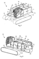
- a bodywork 10 is used in an operating machine 30.
- the machine 30 comprises a central body 31, a pair of arms 35, disposed protruding from the front of the central body 31 and able to support a work tool, for example an excavation or drilling head, and movement means, in this case tracks 32.
- a work tool for example an excavation or drilling head
- the central body 31 comprises a command station 33, a propelling device and maneuvering members 34 of a mechanical, hydraulic, electric or other type, able to drive and move the work tool possibly assembled on the pair of arms 35 and housed in suitable housing compartments 19a, 19b.
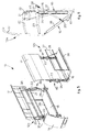
- the bodywork 10 provides a base frame 18 comprising a plurality of uprights and cross elements.
- the bodywork 10 also comprises a plurality of walls 11a, 11b, 12a, 12b, 13a, 13b, 14 and 15, in this case two upper walls 11a and 11b, two external lateral walls 12a and 12b, two internal lateral walls 13a and 13b, a front wall 14 and a rear wall 15.
- the external lateral wall 12a, the upper wall 11a, the internal lateral wall 13a and part of the rear wall 15 are connected to each other so as to define, in cooperation with the corresponding uprights 23 and the cross elements, said housing compartment 19a, to cover and protect part of the maneuvering members 34.
- the external lateral wall 12b, the upper wall 11b, the internal lateral wall 13b and part of the rear wall 15 are connected to each other so as to define, in cooperation with the corresponding uprights 23 and the cross elements, said housing compartment 19b, to cover and protect part of the maneuvering members 34.
- each of the external lateral walls 12a and 12b comprises a support element 16 and a protection element 17, disposed in the closed operating position one adjacent to the other, in a substantially vertical position and partly overlapping.
- each protection element 17 defines, partly or wholly, the visible surface of each of the lateral walls 12a and 12b, while each support element 16 is disposed adjacent to the surface of the relative protection element 17 facing toward the inside of each compartment 19a and 19b.
- the support element 16 and the protection element 17 are adjacent to a pair of uprights 23.
- each lateral wall 12a and 12b comprises a safety railing 37 disposed hinged to an external edge 38 of the support element 16 and, in the closed operating position, adjacent thereto.
- the railing 37 is divided into modules bendable in correspondence with the external edge 38.
- each lateral wall 12a and 12b comprises the support element 16, the protection element 17, a movement unit 40 and command members 41 of the movement unit 40.
- the movement unit 40 moves the protection element 17 with respect to the uprights 23 and connects it kinematically to the support element 16, determining the movement of the latter as described hereafter.
- the command members 41 are of a known type, for example hydraulic or electric or other.
- the movement unit 40 comprises a pair of support elements 22, a shaft 21, two levers 20 of equal length, a pair of cylinders 24, a pair of transmission levers 25, a pair of tie rods 26 and two lever-type kinematisms 42.
- the support elements 22 support a shaft 21 in correspondence with its end zones.
- the levers 20, at a first end, are attached to the shaft 21.
- the second end of the levers 20 is hinged to the protection element 17.
- a cylinder 24 is kinematically connected to each lever 20, has one end pivoted to one of the two uprights 23 and is able to rotate with respect to the upright 23.
- a respective transmission lever 25 is also connected to each upright 23, by means of a first rotation pin 27.
- the transmission lever 25 has one end hinged to the protection element 17 and one end connected to a first end of a respective tie rod 26 by means of a second rotation pin 28.
- each tie rod 26 is connected by means of a third rotation pin 29 to a lateral edge of the support element 16.
- the support element 16 is also kinematically connected to the lower end of each upright 23 by means of a lever-type kinematism 42.
- Fig. 6 shows the detail of the bodywork 10, comprising the support element 16, the protection element 17, the relative movement unit 40 and the command members 41, in a semi-open position.
- the method to open the bodywork 10 shown is as follows.
- the cylinder 24 is driven by means of the command members 41, determining the rotation of the shaft 21 and of the relative levers 20.
- the protection element 17 is moved upward, because it is hinged to the levers 20, allowing to open the compartment 19a.
- the movement of the protection element 17 entails the rotation of the transmission lever 25 around the first rotation pin 27, and the transmission lever 25 transmits motion to the tie rod 26 by means of the second pin 28.
- the tie rod 26, in turn, rotating around the third pin 29, allows the support element 16 to lower, thanks to the lever-type kinematism which connects it to the upright 23.
- the railing 37 is lifted manually by rotating it around the axis of hinging with the support element 16, until it reaches a vertical position.
- the support element 16 assumes in the open condition a substantially horizontal position.
- the shape and sizes of the support element 16 are such that, in the open condition, it defines a walking plane on which the worker can move and access the inspection compartments 19a, 19b of the machine.
- the protection element 17 on the contrary has a conformation such as to function, in the open operating position, as a protective parapet if the workers are operating and moving on the upper walls 11a, 11b.
- each lateral wall 12a and 12b comprises one or more sound-proofing panels, selectively movable, able to reduce the propagation of the noise produced by the propelling device and/or by the mechanical members 34, if the workers are carrying out inspections and/or maintenance operations working on one of the upper walls 11a, 11b when the machine is functioning.
Landscapes
- Engineering & Computer Science (AREA)
- Mechanical Engineering (AREA)
- Combustion & Propulsion (AREA)
- General Engineering & Computer Science (AREA)
- Structural Engineering (AREA)
- Chemical & Material Sciences (AREA)
- Civil Engineering (AREA)
- Transportation (AREA)
- Mining & Mineral Resources (AREA)
- Shovels (AREA)
- Earth Drilling (AREA)
- Power-Operated Mechanisms For Wings (AREA)
- Protection Of Plants (AREA)
Applications Claiming Priority (1)
| Application Number | Priority Date | Filing Date | Title |
|---|---|---|---|
| ITUD2009A000025A IT1392850B1 (it) | 2009-02-06 | 2009-02-06 | Carrozzeria per macchina operatrice e macchina operatrice comprendente tale carrozzeria |
Publications (2)
| Publication Number | Publication Date |
|---|---|
| EP2216238A1 true EP2216238A1 (de) | 2010-08-11 |
| EP2216238B1 EP2216238B1 (de) | 2011-10-05 |
Family
ID=41016914
Family Applications (1)
| Application Number | Title | Priority Date | Filing Date |
|---|---|---|---|
| EP10152565A Active EP2216238B1 (de) | 2009-02-06 | 2010-02-03 | Karosserie für eine Betriebsmaschine und Betriebsmaschine mit der Karosserie |
Country Status (3)
| Country | Link |
|---|---|
| EP (1) | EP2216238B1 (de) |
| AT (1) | ATE527159T1 (de) |
| IT (1) | IT1392850B1 (de) |
Cited By (7)
| Publication number | Priority date | Publication date | Assignee | Title |
|---|---|---|---|---|
| WO2011144734A1 (fr) * | 2010-05-20 | 2011-11-24 | Dynamic Consult Monaco | Machine, notamment engin de chantier, avec système escamotable de protection anti-chute d'un opérateur montant sur le bâti de la machine |
| WO2012022666A1 (en) | 2010-08-20 | 2012-02-23 | Agco International Gmbh | Panel arrangement for a harvesting machine |
| EP2829663A1 (de) | 2013-07-22 | 2015-01-28 | BAUER Maschinen GmbH | Oberwagen für eine Baumaschine |
| CN105274932A (zh) * | 2014-06-17 | 2016-01-27 | 宝马格有限公司 | 具有集成的维护平台的自行式路面铣削机械 |
| JP2016069977A (ja) * | 2014-09-30 | 2016-05-09 | 日立建機株式会社 | 建設機械 |
| CN105714870A (zh) * | 2014-12-05 | 2016-06-29 | 包尔机械有限公司 | 施工机械 |
| US9404238B1 (en) | 2015-01-10 | 2016-08-02 | Bauer Maschinen Gmbh | Construction machine |
Families Citing this family (2)
| Publication number | Priority date | Publication date | Assignee | Title |
|---|---|---|---|---|
| DE202013003459U1 (de) | 2013-04-12 | 2014-07-14 | Liebherr-Werk Nenzing Gmbh | Oberwagen für eine Arbeitsmaschine sowie Arbeitsmaschine |
| DE202020106371U1 (de) | 2020-11-06 | 2022-02-11 | Liebherr-Werk Nenzing Gmbh | Mobilkran mit klappbarer Begehung |
Citations (4)
| Publication number | Priority date | Publication date | Assignee | Title |
|---|---|---|---|---|
| US3860083A (en) * | 1973-01-26 | 1975-01-14 | Caterpillar Tractor Co | Detachable panel arrangement for a tamper proof engine enclosure |
| JPS52141725U (de) * | 1976-04-23 | 1977-10-27 | ||
| JPH0685148U (ja) | 1993-05-24 | 1994-12-06 | 株式会社小松製作所 | 建設機械のウォークスルー用ステップ |
| WO2001076912A1 (en) * | 2000-04-11 | 2001-10-18 | Volvo Articulated Haulers Ab | Power engine housing |
Family Cites Families (1)
| Publication number | Priority date | Publication date | Assignee | Title |
|---|---|---|---|---|
| US6431093B1 (en) * | 2000-08-03 | 2002-08-13 | David A. Hansen | Truck catwalk system |
-
2009
- 2009-02-06 IT ITUD2009A000025A patent/IT1392850B1/it active
-
2010
- 2010-02-03 AT AT10152565T patent/ATE527159T1/de not_active IP Right Cessation
- 2010-02-03 EP EP10152565A patent/EP2216238B1/de active Active
Patent Citations (4)
| Publication number | Priority date | Publication date | Assignee | Title |
|---|---|---|---|---|
| US3860083A (en) * | 1973-01-26 | 1975-01-14 | Caterpillar Tractor Co | Detachable panel arrangement for a tamper proof engine enclosure |
| JPS52141725U (de) * | 1976-04-23 | 1977-10-27 | ||
| JPH0685148U (ja) | 1993-05-24 | 1994-12-06 | 株式会社小松製作所 | 建設機械のウォークスルー用ステップ |
| WO2001076912A1 (en) * | 2000-04-11 | 2001-10-18 | Volvo Articulated Haulers Ab | Power engine housing |
Cited By (11)
| Publication number | Priority date | Publication date | Assignee | Title |
|---|---|---|---|---|
| WO2011144734A1 (fr) * | 2010-05-20 | 2011-11-24 | Dynamic Consult Monaco | Machine, notamment engin de chantier, avec système escamotable de protection anti-chute d'un opérateur montant sur le bâti de la machine |
| WO2012022666A1 (en) | 2010-08-20 | 2012-02-23 | Agco International Gmbh | Panel arrangement for a harvesting machine |
| EP2829663A1 (de) | 2013-07-22 | 2015-01-28 | BAUER Maschinen GmbH | Oberwagen für eine Baumaschine |
| EP3135824A1 (de) | 2013-07-22 | 2017-03-01 | BAUER Maschinen GmbH | Oberwagen für eine baumaschine |
| CN105274932A (zh) * | 2014-06-17 | 2016-01-27 | 宝马格有限公司 | 具有集成的维护平台的自行式路面铣削机械 |
| CN108774942A (zh) * | 2014-06-17 | 2018-11-09 | 宝马格有限公司 | 具有集成的维护平台的自行式路面铣削机械 |
| DE102015007562B4 (de) | 2014-06-17 | 2020-01-16 | Bomag Gmbh | Selbstfahrende Bodenfräsmaschine, insbesondere Straßenfräse, Recycler, Stabilisierer oder Surface-Miner, mit integrierter Wartungsplatte |
| JP2016069977A (ja) * | 2014-09-30 | 2016-05-09 | 日立建機株式会社 | 建設機械 |
| CN105714870A (zh) * | 2014-12-05 | 2016-06-29 | 包尔机械有限公司 | 施工机械 |
| CN105714870B (zh) * | 2014-12-05 | 2018-06-29 | 包尔机械有限公司 | 施工机械 |
| US9404238B1 (en) | 2015-01-10 | 2016-08-02 | Bauer Maschinen Gmbh | Construction machine |
Also Published As
| Publication number | Publication date |
|---|---|
| ITUD20090025A1 (it) | 2010-08-07 |
| EP2216238B1 (de) | 2011-10-05 |
| ATE527159T1 (de) | 2011-10-15 |
| IT1392850B1 (it) | 2012-03-23 |
Similar Documents
| Publication | Publication Date | Title |
|---|---|---|
| EP2216238B1 (de) | Karosserie für eine Betriebsmaschine und Betriebsmaschine mit der Karosserie | |
| CN103826940B (zh) | 刮水器装置、带刮水器装置的开闭防护器以及用于建筑机械的驾驶室 | |
| CN105274932A (zh) | 具有集成的维护平台的自行式路面铣削机械 | |
| EP3258041B1 (de) | Türscharnieranordnung | |
| KR101037948B1 (ko) | 차량용 크레인 운전석 케빈 | |
| JP2009287384A (ja) | レベリングシステムを備えた建設機械用及び林業機械用ステップ装置 | |
| CN208106466U (zh) | 掘护锚机 | |
| CN104695860A (zh) | 综采工作面锚杆钻机及综采工作面采煤锚固一体化设备 | |
| CN109424318A (zh) | 具有远程遥控功能的凿岩台车及其操控方法 | |
| CN103133015A (zh) | 多功能安装机 | |
| EA034047B1 (ru) | Стволопроходческий комбайн | |
| CN110344863A (zh) | 掘护锚机 | |
| KR20140130688A (ko) | 자동 설치 특성을 갖는 비계 | |
| JPS5936078B2 (ja) | 鉱山装置 | |
| CN204753443U (zh) | 电动翻板式道闸 | |
| CN107059842B (zh) | 地下连续墙施工预制墙体配套施工设备及施工方法 | |
| CN102996150B (zh) | 挡矸装置 | |
| CN112227948A (zh) | 一种煤矿用小型单臂钻车 | |
| CN110761796A (zh) | 深斜井扩挖支护装置及施工方法 | |
| CN208932922U (zh) | 一种既有建筑加装电梯用剪式攀爬吊装机 | |
| CN107130786B (zh) | 施工升降平台 | |
| KR101625677B1 (ko) | 건설 중장비용 전방 도어의 개폐 제어 장치 | |
| CN213743235U (zh) | 一种煤矿用小型单臂钻车 | |
| CN207700213U (zh) | 一种电梯井道基础的快速安全施工系统 | |
| CN207700741U (zh) | 一种外墙电梯井道预埋件的快速施工装置 |
Legal Events
| Date | Code | Title | Description |
|---|---|---|---|
| PUAI | Public reference made under article 153(3) epc to a published international application that has entered the european phase |
Free format text: ORIGINAL CODE: 0009012 |
|
| AK | Designated contracting states |
Kind code of ref document: A1 Designated state(s): AT BE BG CH CY CZ DE DK EE ES FI FR GB GR HR HU IE IS IT LI LT LU LV MC MK MT NL NO PL PT RO SE SI SK SM TR |
|
| AX | Request for extension of the european patent |
Extension state: AL BA RS |
|
| 17P | Request for examination filed |
Effective date: 20110204 |
|
| GRAP | Despatch of communication of intention to grant a patent |
Free format text: ORIGINAL CODE: EPIDOSNIGR1 |
|
| RIC1 | Information provided on ipc code assigned before grant |
Ipc: B62D 25/10 20060101AFI20110325BHEP Ipc: E02F 9/16 20060101ALI20110325BHEP Ipc: B60R 3/00 20060101ALI20110325BHEP |
|
| GRAS | Grant fee paid |
Free format text: ORIGINAL CODE: EPIDOSNIGR3 |
|
| GRAA | (expected) grant |
Free format text: ORIGINAL CODE: 0009210 |
|
| AK | Designated contracting states |
Kind code of ref document: B1 Designated state(s): AT BE BG CH CY CZ DE DK EE ES FI FR GB GR HR HU IE IS IT LI LT LU LV MC MK MT NL NO PL PT RO SE SI SK SM TR |
|
| REG | Reference to a national code |
Ref country code: GB Ref legal event code: FG4D |
|
| REG | Reference to a national code |
Ref country code: CH Ref legal event code: EP |
|
| REG | Reference to a national code |
Ref country code: IE Ref legal event code: FG4D |
|
| REG | Reference to a national code |
Ref country code: DE Ref legal event code: R096 Ref document number: 602010000235 Country of ref document: DE Effective date: 20111201 |
|
| REG | Reference to a national code |
Ref country code: NL Ref legal event code: VDEP Effective date: 20111005 |
|
| PG25 | Lapsed in a contracting state [announced via postgrant information from national office to epo] |
Ref country code: SI Free format text: LAPSE BECAUSE OF FAILURE TO SUBMIT A TRANSLATION OF THE DESCRIPTION OR TO PAY THE FEE WITHIN THE PRESCRIBED TIME-LIMIT Effective date: 20111005 |
|
| LTIE | Lt: invalidation of european patent or patent extension |
Effective date: 20111005 |
|
| REG | Reference to a national code |
Ref country code: AT Ref legal event code: MK05 Ref document number: 527159 Country of ref document: AT Kind code of ref document: T Effective date: 20111005 |
|
| PG25 | Lapsed in a contracting state [announced via postgrant information from national office to epo] |
Ref country code: BE Free format text: LAPSE BECAUSE OF FAILURE TO SUBMIT A TRANSLATION OF THE DESCRIPTION OR TO PAY THE FEE WITHIN THE PRESCRIBED TIME-LIMIT Effective date: 20111005 Ref country code: LT Free format text: LAPSE BECAUSE OF FAILURE TO SUBMIT A TRANSLATION OF THE DESCRIPTION OR TO PAY THE FEE WITHIN THE PRESCRIBED TIME-LIMIT Effective date: 20111005 Ref country code: IS Free format text: LAPSE BECAUSE OF FAILURE TO SUBMIT A TRANSLATION OF THE DESCRIPTION OR TO PAY THE FEE WITHIN THE PRESCRIBED TIME-LIMIT Effective date: 20120205 Ref country code: NO Free format text: LAPSE BECAUSE OF FAILURE TO SUBMIT A TRANSLATION OF THE DESCRIPTION OR TO PAY THE FEE WITHIN THE PRESCRIBED TIME-LIMIT Effective date: 20120105 |
|
| PG25 | Lapsed in a contracting state [announced via postgrant information from national office to epo] |
Ref country code: HR Free format text: LAPSE BECAUSE OF FAILURE TO SUBMIT A TRANSLATION OF THE DESCRIPTION OR TO PAY THE FEE WITHIN THE PRESCRIBED TIME-LIMIT Effective date: 20111005 Ref country code: GR Free format text: LAPSE BECAUSE OF FAILURE TO SUBMIT A TRANSLATION OF THE DESCRIPTION OR TO PAY THE FEE WITHIN THE PRESCRIBED TIME-LIMIT Effective date: 20120106 Ref country code: PT Free format text: LAPSE BECAUSE OF FAILURE TO SUBMIT A TRANSLATION OF THE DESCRIPTION OR TO PAY THE FEE WITHIN THE PRESCRIBED TIME-LIMIT Effective date: 20120206 Ref country code: SE Free format text: LAPSE BECAUSE OF FAILURE TO SUBMIT A TRANSLATION OF THE DESCRIPTION OR TO PAY THE FEE WITHIN THE PRESCRIBED TIME-LIMIT Effective date: 20111005 Ref country code: NL Free format text: LAPSE BECAUSE OF FAILURE TO SUBMIT A TRANSLATION OF THE DESCRIPTION OR TO PAY THE FEE WITHIN THE PRESCRIBED TIME-LIMIT Effective date: 20111005 Ref country code: LV Free format text: LAPSE BECAUSE OF FAILURE TO SUBMIT A TRANSLATION OF THE DESCRIPTION OR TO PAY THE FEE WITHIN THE PRESCRIBED TIME-LIMIT Effective date: 20111005 |
|
| PG25 | Lapsed in a contracting state [announced via postgrant information from national office to epo] |
Ref country code: CY Free format text: LAPSE BECAUSE OF FAILURE TO SUBMIT A TRANSLATION OF THE DESCRIPTION OR TO PAY THE FEE WITHIN THE PRESCRIBED TIME-LIMIT Effective date: 20111005 |
|
| PG25 | Lapsed in a contracting state [announced via postgrant information from national office to epo] |
Ref country code: BG Free format text: LAPSE BECAUSE OF FAILURE TO SUBMIT A TRANSLATION OF THE DESCRIPTION OR TO PAY THE FEE WITHIN THE PRESCRIBED TIME-LIMIT Effective date: 20120105 Ref country code: SK Free format text: LAPSE BECAUSE OF FAILURE TO SUBMIT A TRANSLATION OF THE DESCRIPTION OR TO PAY THE FEE WITHIN THE PRESCRIBED TIME-LIMIT Effective date: 20111005 Ref country code: EE Free format text: LAPSE BECAUSE OF FAILURE TO SUBMIT A TRANSLATION OF THE DESCRIPTION OR TO PAY THE FEE WITHIN THE PRESCRIBED TIME-LIMIT Effective date: 20111005 Ref country code: DK Free format text: LAPSE BECAUSE OF FAILURE TO SUBMIT A TRANSLATION OF THE DESCRIPTION OR TO PAY THE FEE WITHIN THE PRESCRIBED TIME-LIMIT Effective date: 20111005 Ref country code: CZ Free format text: LAPSE BECAUSE OF FAILURE TO SUBMIT A TRANSLATION OF THE DESCRIPTION OR TO PAY THE FEE WITHIN THE PRESCRIBED TIME-LIMIT Effective date: 20111005 |
|
| PLBE | No opposition filed within time limit |
Free format text: ORIGINAL CODE: 0009261 |
|
| STAA | Information on the status of an ep patent application or granted ep patent |
Free format text: STATUS: NO OPPOSITION FILED WITHIN TIME LIMIT |
|
| PG25 | Lapsed in a contracting state [announced via postgrant information from national office to epo] |
Ref country code: PL Free format text: LAPSE BECAUSE OF FAILURE TO SUBMIT A TRANSLATION OF THE DESCRIPTION OR TO PAY THE FEE WITHIN THE PRESCRIBED TIME-LIMIT Effective date: 20111005 Ref country code: RO Free format text: LAPSE BECAUSE OF FAILURE TO SUBMIT A TRANSLATION OF THE DESCRIPTION OR TO PAY THE FEE WITHIN THE PRESCRIBED TIME-LIMIT Effective date: 20111005 |
|
| 26N | No opposition filed |
Effective date: 20120706 |
|
| PG25 | Lapsed in a contracting state [announced via postgrant information from national office to epo] |
Ref country code: MC Free format text: LAPSE BECAUSE OF NON-PAYMENT OF DUE FEES Effective date: 20120229 |
|
| REG | Reference to a national code |
Ref country code: DE Ref legal event code: R097 Ref document number: 602010000235 Country of ref document: DE Effective date: 20120706 |
|
| REG | Reference to a national code |
Ref country code: IE Ref legal event code: MM4A |
|
| PG25 | Lapsed in a contracting state [announced via postgrant information from national office to epo] |
Ref country code: IE Free format text: LAPSE BECAUSE OF NON-PAYMENT OF DUE FEES Effective date: 20120203 Ref country code: AT Free format text: LAPSE BECAUSE OF FAILURE TO SUBMIT A TRANSLATION OF THE DESCRIPTION OR TO PAY THE FEE WITHIN THE PRESCRIBED TIME-LIMIT Effective date: 20111005 |
|
| PG25 | Lapsed in a contracting state [announced via postgrant information from national office to epo] |
Ref country code: MK Free format text: LAPSE BECAUSE OF FAILURE TO SUBMIT A TRANSLATION OF THE DESCRIPTION OR TO PAY THE FEE WITHIN THE PRESCRIBED TIME-LIMIT Effective date: 20111005 |
|
| PG25 | Lapsed in a contracting state [announced via postgrant information from national office to epo] |
Ref country code: ES Free format text: LAPSE BECAUSE OF FAILURE TO SUBMIT A TRANSLATION OF THE DESCRIPTION OR TO PAY THE FEE WITHIN THE PRESCRIBED TIME-LIMIT Effective date: 20120116 |
|
| PGFP | Annual fee paid to national office [announced via postgrant information from national office to epo] |
Ref country code: FR Payment date: 20130301 Year of fee payment: 4 |
|
| PG25 | Lapsed in a contracting state [announced via postgrant information from national office to epo] |
Ref country code: FI Free format text: LAPSE BECAUSE OF FAILURE TO SUBMIT A TRANSLATION OF THE DESCRIPTION OR TO PAY THE FEE WITHIN THE PRESCRIBED TIME-LIMIT Effective date: 20111005 |
|
| PG25 | Lapsed in a contracting state [announced via postgrant information from national office to epo] |
Ref country code: MT Free format text: LAPSE BECAUSE OF FAILURE TO SUBMIT A TRANSLATION OF THE DESCRIPTION OR TO PAY THE FEE WITHIN THE PRESCRIBED TIME-LIMIT Effective date: 20111005 |
|
| PG25 | Lapsed in a contracting state [announced via postgrant information from national office to epo] |
Ref country code: TR Free format text: LAPSE BECAUSE OF FAILURE TO SUBMIT A TRANSLATION OF THE DESCRIPTION OR TO PAY THE FEE WITHIN THE PRESCRIBED TIME-LIMIT Effective date: 20111005 |
|
| PGFP | Annual fee paid to national office [announced via postgrant information from national office to epo] |
Ref country code: DE Payment date: 20140219 Year of fee payment: 5 |
|
| PG25 | Lapsed in a contracting state [announced via postgrant information from national office to epo] |
Ref country code: LU Free format text: LAPSE BECAUSE OF NON-PAYMENT OF DUE FEES Effective date: 20120203 Ref country code: SM Free format text: LAPSE BECAUSE OF FAILURE TO SUBMIT A TRANSLATION OF THE DESCRIPTION OR TO PAY THE FEE WITHIN THE PRESCRIBED TIME-LIMIT Effective date: 20111005 |
|
| PG25 | Lapsed in a contracting state [announced via postgrant information from national office to epo] |
Ref country code: HU Free format text: LAPSE BECAUSE OF FAILURE TO SUBMIT A TRANSLATION OF THE DESCRIPTION OR TO PAY THE FEE WITHIN THE PRESCRIBED TIME-LIMIT Effective date: 20100203 |
|
| REG | Reference to a national code |
Ref country code: CH Ref legal event code: PL |
|
| GBPC | Gb: european patent ceased through non-payment of renewal fee |
Effective date: 20140203 |
|
| PG25 | Lapsed in a contracting state [announced via postgrant information from national office to epo] |
Ref country code: CH Free format text: LAPSE BECAUSE OF NON-PAYMENT OF DUE FEES Effective date: 20140228 Ref country code: LI Free format text: LAPSE BECAUSE OF NON-PAYMENT OF DUE FEES Effective date: 20140228 |
|
| REG | Reference to a national code |
Ref country code: FR Ref legal event code: ST Effective date: 20141031 |
|
| PG25 | Lapsed in a contracting state [announced via postgrant information from national office to epo] |
Ref country code: FR Free format text: LAPSE BECAUSE OF NON-PAYMENT OF DUE FEES Effective date: 20140228 Ref country code: GB Free format text: LAPSE BECAUSE OF NON-PAYMENT OF DUE FEES Effective date: 20140203 |
|
| REG | Reference to a national code |
Ref country code: DE Ref legal event code: R119 Ref document number: 602010000235 Country of ref document: DE |
|
| PG25 | Lapsed in a contracting state [announced via postgrant information from national office to epo] |
Ref country code: DE Free format text: LAPSE BECAUSE OF NON-PAYMENT OF DUE FEES Effective date: 20150901 |
|
| P01 | Opt-out of the competence of the unified patent court (upc) registered |
Effective date: 20230419 |
|
| PGFP | Annual fee paid to national office [announced via postgrant information from national office to epo] |
Ref country code: IT Payment date: 20240216 Year of fee payment: 15 |