EP2215402B1 - Nivellierungsvorrichtung zur höhenverstellbaren montage einer leuchte - Google Patents
Nivellierungsvorrichtung zur höhenverstellbaren montage einer leuchte Download PDFInfo
- Publication number
- EP2215402B1 EP2215402B1 EP08802804.8A EP08802804A EP2215402B1 EP 2215402 B1 EP2215402 B1 EP 2215402B1 EP 08802804 A EP08802804 A EP 08802804A EP 2215402 B1 EP2215402 B1 EP 2215402B1
- Authority
- EP
- European Patent Office
- Prior art keywords
- lamp
- mounting bracket
- screw
- spring
- ceiling
- Prior art date
- Legal status (The legal status is an assumption and is not a legal conclusion. Google has not performed a legal analysis and makes no representation as to the accuracy of the status listed.)
- Active
Links
- 238000007789 sealing Methods 0.000 claims description 5
- 238000011161 development Methods 0.000 description 2
- 230000018109 developmental process Effects 0.000 description 2
- 238000009434 installation Methods 0.000 description 2
- 230000001419 dependent effect Effects 0.000 description 1
- 239000000463 material Substances 0.000 description 1
- 239000002184 metal Substances 0.000 description 1
- 230000007704 transition Effects 0.000 description 1
- 239000002023 wood Substances 0.000 description 1
Images


Classifications
-
- F—MECHANICAL ENGINEERING; LIGHTING; HEATING; WEAPONS; BLASTING
- F21—LIGHTING
- F21V—FUNCTIONAL FEATURES OR DETAILS OF LIGHTING DEVICES OR SYSTEMS THEREOF; STRUCTURAL COMBINATIONS OF LIGHTING DEVICES WITH OTHER ARTICLES, NOT OTHERWISE PROVIDED FOR
- F21V21/00—Supporting, suspending, or attaching arrangements for lighting devices; Hand grips
- F21V21/02—Wall, ceiling, or floor bases; Fixing pendants or arms to the bases
- F21V21/04—Recessed bases
-
- F—MECHANICAL ENGINEERING; LIGHTING; HEATING; WEAPONS; BLASTING
- F21—LIGHTING
- F21Y—INDEXING SCHEME ASSOCIATED WITH SUBCLASSES F21K, F21L, F21S and F21V, RELATING TO THE FORM OR THE KIND OF THE LIGHT SOURCES OR OF THE COLOUR OF THE LIGHT EMITTED
- F21Y2103/00—Elongate light sources, e.g. fluorescent tubes
Definitions
- the present invention relates to a leveling device for a luminaire, which allows a height-adjustable mounting of the lamp, in particular in a ceiling.
- mounting brackets are used, which are bolted to the back of a ceiling above an opening for a lamp.
- the luminaire housing of the slotlight lights are screwed to the central area of the U-shaped mounting bracket.
- the wings of the U-shaped mounting brackets are now adjustable in length by means of screws, whereby the luminaire housing can be adjusted flush with the ceiling.
- a tab is attached in each case with which the mounting bracket can be screwed to the ceiling.
- a sheet is provided, which is pressed by attaching the lamp to the mounting device by pressing the lamp in the ceiling, whereby an adjustment of the lamp housing can be made according to a ceiling.
- the leveling of the lamp can be made without disassembly of the lamp, however, is the leveling the lamp only in one direction possible because the compressed metal sheet can not push the lamp back in the other direction.
- no correction in the other direction can be made more.
- the present invention is based on the object to improve a device for mounting a lamp in a ceiling such that a leveling of the lamp housing without disassembly of the lamp is possible and the leveling can be made in both directions.
- a leveling device for height-adjustable mounting a lamp used which has a mounting bracket, a screw and a spring.
- the screw serves to attach the lamp to the mounting bracket, the spring between the lamp and the mounting bracket is effective.
- the mounting bracket is U-shaped and the spring is wing-like with a central region and V-shaped wings open.
- the mounting bracket also has elongated openings in the corners of the U-shape and the wings of the spring pass through the elongated openings in the mounting bracket.
- the U-shaped configuration of the mounting bracket of the leveling device is particularly advantageous in the current light housings, such as the slotlight light housings, due to their shape.
- the luminaire may be fastened to the screw with a slotted disc and a sealing element may be mounted between the spring and the luminaire. Due to the slotted a simple and fast attachment of the lamp in the mounting bracket is now possible and in addition is closed by the sealing element of the interior of the lamp housing, so that the lamp can meet, for example, the requirements for the protection IP54.
- the mounting bracket still has two additional tabs, which have a hole pattern.
- the hole pattern makes it easy to attach the mounting bracket to a ceiling because it is not necessary to hit a specific hole, but only the area of the tabs.
- the screw is held by a nut on the mounting bracket.
- the hole through which the screw engages through the mounting bracket formed as a longitudinal hole, whereby a slight adjustment of the lamp in the transverse direction is possible.
- the leveling device 1 according to the invention is explained individually. Subsequently, the leveling device 1 according to the invention as a whole - ie in the assembled state - considered in more detail.
- the Fig. 1a and 1b show a spring 3 of the leveling device 1 according to the invention in two different views.
- This is a wing-like spring 3 having a central region 10 and two V-shaped wings 11 which adjoin the central region 10.
- the central region 10 also has a circular hole 12 in the center.
- FIG. 2a shows the mounting bracket in not yet bent form from above, in FIG. 2b however, the mounting bracket 2 is already bent and in a lateral view.
- the mounting wing 2 has a U-shape with a central area 13 and two wings 14 extending from the central area 13.
- a tab 8 is arranged at right angles at the ends of the two wings 14.
- the tabs 8 are used to attach the mounting bracket 2 to a ceiling 18 and have for this purpose a hole pattern, whereby the assembly is significantly simplified because when mounting the bracket 2 to a ceiling by screwing not exactly a special hole in the tab 8 are taken must, but only the area of the tab 8.
- the central region 13 of the mounting bracket 2 also has an elongated hole 15 extending in the direction of the two wings 14. In the two corners of the U-shape, ie in the transitions from the central region 13 to the wings 14, in addition, in each case a transversely extending opening 9 is attached.
- the 3 and 4 Now show a leveling device 1 according to the invention for height-adjustable mounting a lamp 19 in the assembled state or mounted on a ceiling with a lamp.
- a leveling device 1 according to the invention is shown in the assembled state.
- the spring 3 is fastened by means of a screw 4 to the mounting bracket 2.
- the screw 4 extends through the circular opening 12 of the spring 2 and through the elongated opening 15 of the mounting bracket 2.
- the central portion 10 of the spring 2 is in this case within the U-shape of the mounting bracket 2 and is parallel to the central region 13 of the Mounting bracket 2 is arranged.
- the screw head of the screw 4 is located on the underside - the side facing away from the central region 13 of the mounting bracket 2 - the central portion 10 of the spring 3.
- On the outside - the side facing away from the central region 10 of the spring 3 - the central portion 13 of the Mounting bracket 2 is further attached a nut 7, which holds the screw 4 on the mounting bracket 2.
- the spring 3 is held by the screw 4 and the nut 7 in the mounting bracket 2.
- a sealing washer 6 and a slotted disc 5 are far away arranged whose function will be described in more detail below.
- a leveling device 1 according to the invention is shown, which is attached to a ceiling 18, for which the already in the Fig. 2a and 2b described tabs 8 of the mounting bracket 2 are used.
- These are in particular suspended ceilings, for example made of plasterboard.
- wood ceilings or ceilings made of other materials would be conceivable.
- screws 17 are screwed from the bottom completely through the ceiling 18 and then through the hole pattern in the tabs 8 of the mounting bracket 2. The hole pattern, it is not necessary that the screws 17 exactly at a certain point through the ceiling 18th must be screwed, but only in the tabs. 8
- a luminaire housing 16 a lamp 19 attached.
- the luminaire housing 16 is held on the screw head of the screw 4 in this case by the slotted disc 5.
- the slotted disc 5 For mounting the lamp housing 16, the slotted disc 5 must first be removed from the screw 4. Subsequently, the screw head of the screw 4 can be passed through a hole located in the lamp housing 16, said hole having approximately the size of the screw head. Subsequently, the slotted disc 5 is again attached to the screw 4, whereby the lamp housing 16 is held on the screw 4. It should be noted that the diameter of the slotted disc 5 must be larger than the hole in the lamp housing 16.
- a sealing element 6 is provided between the spring 3 and the luminaire housing 16. This seal member 6 is compressed between the spring 3 and the lamp housing 16, whereby the opening of the lamp housing 16 is sealed.
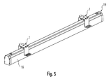
- a lamp 19 is shown in a 3D view at the example of two leveling devices 1 according to the invention are mounted.
- the number of leveling devices 1 which are attached to a lamp 19 here is arbitrary and may depend, for example, on the use of the lamp 19.
- FIGS. 1 to 5 shown leveling device 1 according to the invention is only one possible embodiment of the present invention. So it is not absolutely necessary that the mounting bracket 2 is screwed to the ceiling 18. Another type of fixation would be conceivable. However, it makes sense to attach the mounting bracket 2 in any way on the ceiling 18, since at the latest when introducing an example transparent cover in the bottom of a lamp housing 16, a certain pressure on the leveling device 1 is exercised.
Landscapes
- Engineering & Computer Science (AREA)
- General Engineering & Computer Science (AREA)
- Arrangement Of Elements, Cooling, Sealing, Or The Like Of Lighting Devices (AREA)
Description
- Die vorliegende Erfindung betrifft eine Nivellierungsvorrichtung für eine Leuchte, die eine höhenverstellbare Montage der Leuchte insbesondere in einer Decke ermöglicht.
- Um Leuchten in Decken beispielsweise Gipskartondecken einzubauen und bündig mit den Decken zu nivellieren, stehen verschiedene Montagevorrichtungen, die diese Aufgabe erfüllen, zur Verfügung. So kommen, beispielsweise bei den sogenannten Slotlight-Leuchten der Anmelderin, Befestigungsbügel zum Einsatz, die an der Rückseite einer Decke oberhalb einer Öffnung für eine Leuchte verschraubt werden. Dabei werden die Leuchtengehäuse der Slotlight-Leuchten an dem zentralen Bereich der u-förmigen Befestigungsbügel angeschraubt. Für die genaue Nivellierung der Leuchte im Bezug zur Decke sind nun die Flügel der u-förmigen Befestigungsbügel in ihrer Länge mit Hilfe von Schrauben verstellbar, wodurch das Leuchtengehäuse bündig mit der Decke eingestellt werden kann. An den Enden der Flügel des uförmigen Befestigungsbügels ist jeweils eine Lasche angebracht mit der der Befestigungsbügel an der Decke verschraubt werden kann.
- Bei diesem Befestigungsbügel ist zwar eine Nivellierung der Leuchte in beide Richtungen - in die Decke hinein und aus der Decke heraus - möglich, jedoch muss das Verstellen der Flügel bereits vor der Montage des Befestigungsbügels auf der Decke ausgeführt werden. Somit ist ein nachträgliches nivellieren des Leuchtenkörpers ohne Demontage der Leuchte und möglicherweise sogar des Befestigungsbügels nicht möglich, wodurch der Montageaufwand der Leuchte dementsprechend groß ist, da bereits bei der Montage des Befestigungsbügels die genaue Höhe der Leuchte im Bezug zur Decke ermittelt und eingestellt werden muss.
- Bei einer anderen Montagevorrichtung ist ein Blech vorgesehen, das nach Befestigung der Leuchte an der Montagevorrichtung durch drücken der Leuchte in die Decke zusammengepresst wird, wodurch eine Einstellung des Leuchtengehäuses entsprechend einer Decke vorgenommen werden kann. Bei einer derartigen Montagevorrichtung ist es nun zwar möglich, dass die Nivellierung der Leuchte auch ohne Demontage der Leuchte vorgenommen werden kann, jedoch ist die Nivellierung der Leuchte nur in eine Richtung möglich, da das zusammengepresste Blech die Leuchte nicht wieder in die andere Richtung drücken kann. Somit kann hier bei versehentlichen zu weitem Eindrücken der Leuchte in die Decke keine Korrektur in die andere Richtung mehr vorgenommen werden.
- Auch in der
US 2,854,205 und derDE 297 22 234 U1 sind Leuchten gezeigt, die Montagevorrichtungen zur Befestigung der Leuchten beispielsweise in Decken aufweisen. - Der vorliegenden Erfindung liegt nun die Aufgabe zugrunde, eine Vorrichtung zur Montage einer Leuchte in einer Decke derart zu verbessern, dass eine Nivellierung des Leuchtengehäuses auch ohne Demontage der Leuchte möglich ist und die Nivellierung in beide Richtungen vorgenommen werden kann.
- Die Aufgabe wird durch eine Nivellierungsvorrichtung gemäß Anspruch 1 gelöst. Vorteilhafte Weiterbildungen der Erfindung sind Gegenstand der abhängigen Ansprüche.
- Erfindungsgemäß kommt nun eine Nivellierungsvorrichtung zur höhenverstellbaren Montage einer Leuchte zum Einsatz, die einen Montagebügel, eine Schraube und eine Feder aufweist. Die Schraube dient hierbei zur Befestigung der Leuchte an dem Montagebügel, wobei die Feder zwischen der Leuchte und dem Montagebügel wirksam ist. Der Montagebügel ist U-förmig ausgebildet und die Feder ist flügelartig mit einem zentralen Bereich und V-förmig geöffneten Flügeln ausgebildet. Der Montagebügel weist außerdem längliche Öffnungen in den Ecken der U-Form auf und die Flügel der Feder durchgreifen die länglichen Öffnungen in dem Montagebügel.
- Durch diese Ausgestaltung der Nivellierungsvorrichtung ist es nun möglich, ein Leuchtengehäuse auch ohne Demontage der Leuchte in beide Richtungen zu nivellieren, da mit Hilfe der Schraube nunmehr die Höhe der Leuchte eingestellt werden kann, wobei durch die Feder sichergestellt ist, dass die Leuchte immer unter einer entsprechenden Spannung innerhalb des Montagebügels aufgenommen ist, womit auch bei einem Herausdrehen der Schraube das Leuchtengehäuse entsprechend nach außen gedrückt wird.
- Die U-förmige Ausgestaltung des Montagebügels der Nivellierungsvorrichtung ist insbesondere bei den gängigen Leuchtengehäusen, wie beispielsweise den Slotlight-Leuchtengehäusen, aufgrund deren Form von Vorteil.
- Zusätzlich kann die Leuchte mit einer Schlitzscheibe an der Schraube befestigt sein und ein Dichtelement zwischen der Feder und der Leuchte angebracht sein. Aufgrund der Schlitzscheibe ist nun eine einfache und schnelle Befestigung der Leuchte in dem Montagebügel möglich und zusätzlich wird durch das Dichtelement der Innenraum des Leuchtengehäuses verschlossen, sodass die Leuchte beispielsweise die Voraussetzungen für die Schutzart IP54 erfüllen kann.
- Gemäß vorteilhafter Weiterbildungen der Erfindung weist der Montagebügel noch zwei zusätzliche Laschen auf, die ein Lochmuster aufweisen. Durch das Lochmuster ist eine einfach Befestigung des Montagebügels an einer Decke möglich, da nicht genau ein bestimmtes Loch getroffen werden muss, sondern nur der Bereich der Laschen.
- Vorteilhafterweise wird die Schraube durch eine Mutter an dem Montagebügel gehalten. Dabei ist vorzugsweise das Loch, durch welches die Schraube durch den Montagebügel greift, als Längsloch ausgebildet, wodurch eine geringfügige Verstellung der Leuchte in Querrichtung möglich ist. Durch die Verwendung einer Mutter ist es möglich, dass die Schraube sich beim Anziehen durch die Mutter hindurch weiter nach oben erstrecken kann.
- Nachfolgend soll die Erfindung anhand der beiden Zeichnungen näher erläutert werden. Es zeigen:
- Fig. 1a und 1b
- zwei Ansichten eines Montagebügels einer erfindungsgemäßen Nivellierungsvorrichtung,
- Fig. 2a und 2b
- zwei Ansichten einer Feder einer erfindungsgemäßen Nivellierungsvorrichtung,
- Fig. 3
- eine erfindungsgemäße Nivellierungsvorrichtung in 3D-Ansicht,
- Fig. 4
- eine an einer Decke montierte erfindungsgemäße Nivellierungsvorrichtung mit einer Leuchte im Querschnitt,
- Fig. 5
- eine Leuchte mit zwei an ihr angebrachten erfindungsgemäße Nivellierungsvorrichtungen in 3D-Ansicht.
- Nachfolgend werden zuerst die beiden Hauptbauteile, die Feder 3 und der Montagebügel 2, der erfindungsgemäßen Nivellierungsvorrichtung 1 einzeln erläutert. Anschließend wird die erfindungsgemäße Nivellierungsvorrichtung 1 im gesamten - also im zusammengebauten Zustand - genauer betrachtet.
- Die
Fig. 1a und 1b zeigen eine Feder 3 der erfindungsgemäßen Nivellierungsvorrichtung 1 in zwei verschiedenen Ansichten. Hierbei handelt es sich um eine flügelartige ausgebildete Feder 3 mit einem zentralen Bereich 10 und zwei an den zentralen Bereich 10 anschließende V-förmig geöffnete Flügel 11. Der zentrale Bereich 10 weist des Weiteren mittig noch ein rundes Loch 12 auf. - In den
Fig. 2a und 2b ist ein Montagebügel 2 einer erfindungsgemäßen Nivellierungsvorrichtung 1 in zwei Ansichten dargestellt.Figur 2a zeigt den Montagebügel in noch nicht gebogener Form von oben, inFigur 2b hingegen ist der Montagebügel 2 bereits gebogen und in seitlicher Ansicht. In gebogener Form weist der Montageflügel 2 eine U-Form mit einem zentralen Bereich 13 und zwei sich von dem zentralen Bereich 13 erstreckende Flügel 14 auf. Zusätzlich ist an den Enden der beiden Flügel 14 jeweils eine Lasche 8 rechtwinklig angeordnet. Die Laschen 8 dienen zur Befestigung des Montagebügels 2 an einer Decke 18 und weisen hierfür ein Lochmuster auf, wodurch die Montage deutlich vereinfacht wird, da bei der Befestigung des Bügels 2 an einer Decke mittels Verschrauben nicht genau ein spezielles Loch in der Lasche 8 getroffen werden muss, sondern nur der Bereich der Lasche 8. - Der zentrale Bereich 13 des Montagebügels 2 weist außerdem ein sich in Richtung der beiden Flügel 14 erstreckendes längliches Loch 15 auf. In den beiden Ecken der U-Form, also in den Übergängen vom zentralen Bereich 13 zu den Flügeln 14, ist des Weiteren noch jeweils eine sich quererstreckende Öffnung 9 angebracht.
- Die
Fig. 3 und 4 zeigen nun eine erfindungsgemäße Nivellierungsvorrichtung 1 zur höhenverstellbaren Montage einer Leuchte 19 im zusammengebauten Zustand bzw. an einer Decke mit einer Leuchte montiert. - In
Fig. 3 ist eine erfindungsgemäße Nivellierungsvorrichtung 1 im zusammengebauten Zustand dargestellt. Hierbei wird die Feder 3 mit Hilfe einer Schraube 4 an dem Montagebügel 2 befestigt. Hierzu erstreckt sich die Schraube 4 durch die runde Öffnung 12 der Feder 2 und durch die längliche Öffnung 15 des Montagebügels 2. Der zentrale Bereich 10 der Feder 2 befindet sich hierbei innerhalb der U-Form des Montagebügels 2 und ist parallel zum zentralen Bereich 13 des Montagebügels 2 angeordnet. Die sich von dem zentralen Bereich 10 der Feder 3 V-förmig erstreckenden Flügel 11 durchgreifen dabei die quer angeordneten Öffnungen 9 des Montagebügels 2. - Der Schraubenkopf der Schraube 4 befindet sich an der Unterseite - der dem zentralen Bereich 13 des Montagebügels 2 abgewandeten Seite - des zentralen Bereichs 10 der Feder 3. An der Außenseite - der dem zentralen Bereich 10 der Feder 3 abgewandeten Seite - des zentralen Bereichs 13 des Montagebügels 2 ist des Weiteren eine Mutter 7 angebracht, die die Schraube 4 an dem Montagebügel 2 hält. Somit wird die Feder 3 durch die Schraube 4 und die Mutter 7 in dem Montagebügel 2 gehalten. Zwischen der Feder 3 und dem Schraubenkopf der Schraube 4 sind des Weitem noch eine Dichtscheibe 6 und eine Schlitzscheibe 5 angeordnet, deren Funktion weiter unten noch genauer beschrieben wird.
- In
Fig. 4 ist nunmehr eine erfindungsgemäße Nivellierungsvorrichtung 1 gezeigt, die an einer Decke 18 befestigt ist, wofür die bereits bei denFig. 2a und 2b beschrieben Laschen 8 des Montagebügels 2 verwendet werden. Hierbei handelt sich insbesondere um abgehängte Decken, beispielsweise aus Gipskarton. Es wären allerdings auch Holzdecken oder Decken aus anderen Materialien denkbar. Zur Befestigung des Montagebügels 2 werden nun Schrauben 17 von der Unterseite vollständig durch die Decke 18 geschraubt und anschließend auch durch das Lochmuster in den Laschen 8 des Montagebügels 2. Durch das Lochmuster ist es nicht erforderlich, dass die Schrauben 17 genau an einer bestimmten Stelle durch die Decke 18 geschraubt werden müssen, sondern lediglich im Bereich der Laschen 8. - Des Weiteren ist an der erfindungsgemäßen Nivellierungsvorrichtung 1 in
Fig. 4 ein Leuchtengehäuse 16 einer Leuchte 19 angebracht. Das Leuchtengehäuse 16 wird an dem Schraubenkopf der Schraube 4 hierbei durch die Schlitzscheibe 5 gehalten. Zur Montage des Leuchtengehäuses 16 muss die Schlitzscheibe 5 zuerst von der Schraube 4 entfernt werden. Anschließend kann der Schraubenkopf der Schraube 4 durch ein in dem Leuchtengehäuse 16 befindliches Loch hindurchgeführt werden, wobei dieses Loch in etwa die Größe des Schraubenkopfs aufweist. Anschließend wird die Schlitzscheibe 5 wieder an die Schraube 4 angebracht, wodurch das Leuchtengehäuse 16 an der Schraube 4 gehalten wird. Dabei ist zu beachten, dass der Durchmesser der Schlitzscheibe 5 größer als das Loch in dem Leuchtengehäuse 16 sein muss. - Durch das längliche Loch 15 im zentralen Bereich 13 des Montageblechs 2 ist nun eine geringfügige Verstellung der Leuchte in Querrichtung innerhalb der Deckenöffnung möglich.
- Je nach Ausführung des Leuchtengehäuses 16 muss vor Beginn der Montage allerdings noch ein möglicherweise vorhandenes Abdeckungsprofil und in dem Leuchtengehäuse 16 befindliche Leuchtmittel und elektronische Steuermittel entfernt werden.
- Um nun trotz der Öffnung in dem Leuchtengehäuse 16 zur Durchführung des Schraubenkopfs der Schraube 4 eine Leuchte 19 nach dem IP54 Standard zu ermöglichen, ist zwischen der Feder 3 und dem Leuchtengehäuse 16 noch ein Dichtungselement 6 vorgesehen. Dieses Dichtungselement 6 wird zwischen der Feder 3 und dem Leuchtengehäuse 16 zusammengepresst, wodurch die Öffnung des Leuchtengehäuses 16 abgedichtet wird.
- Nachdem das Leuchtengehäuse 16 an der Schraube 4 befestigt ist, kann es nun durch die Schraube 4 in seiner Höhe verstellt werden. Hierbei ist zu beachten, dass im nicht gespannten Zustand der Feder 3, der Montagebügel 2, die Feder 3 und die Schraube 4 derart ausgelegt sein müssen, dass die Leuchte 19 noch etwas über die Decke 18 hinaus steht.
- Um die Leuchte 19 nun weiter in die Decke 18 hinein zufahren, muss lediglich die Schraube 4 weiter in die Mutter 7 eingeschraubt werden, sodass die Schraube 4 die Feder 3 unter Spannung versetzt indem der Raum zwischen dem zentralen Bereich 10 der Feder 3 und dem zentralen Bereich 13 des Montageblechs 2 verkleinert wird. Falls die Leuchte 19 dann versehentlich zu weit in die Decke 18 hinein gefahren wird, kann dann durch Herausschrauben der Schraube 4 aus der Mutter 7 die Leuchte 19 wieder etwas aus der Decke 18 herausgefahren werden, da durch die Spannung der Feder 3 die Leuchte 19 herausgedrückt wird. Somit ist es nun möglich dass eine Leuchte 19 auf einfache Weise in beide Richtungen nivellierbar ist, ohne den Aufwand einer vollständigen Demontage der Leuchte 19 durchführen zu müssen.
- In
Fig. 5 ist nun noch eine Leuchte 19 in 3D-Ansicht gezeigt, an der beispielhaft zwei erfindungsgemäße Nivelliervorrichtungen 1 angebracht sind. Die Anzahl der Nivelliervorrichtungen 1 die an einer Leuchte 19 angebracht sind ist hierbei beliebig und kann beispielsweise von der Verwendung der Leuchte 19 abhängen. - Die in den
Figuren 1 bis 5 gezeigte erfindungsgemäße Nivellierungsvorrichtung 1 ist lediglich eine mögliche Ausführungsform der vorliegenden Erfindung. So ist es nicht zwingend erforderlich, dass der Montagebügel 2 mit der Decke 18 verschraubt wird. Auch eine andere Art der Fixierung wäre denkbar. Jedoch ist es sinnvoll, den Montagebügel 2 in irgendeiner Art und Weise an der Decke 18 zu befestigen, da spätestens beim Einbringen einer beispielsweise transparenten Abdeckung in die Unterseite eines Leuchtengehäuses 16 ein gewisser Druck auf die Nivellierungsvorrichtung 1 ausgeübt wird. - Des Weiteren ist die hier vorgestellte Feder 3 lediglich eine mögliche Ausführungsform der vorliegenden Erfindung.
Claims (8)
- Nivellierungsvorrichtung (1) zur höhenverstellbaren Montage einer Leuchte (19) insbesondere in einer Decke (18), aufweisend einen Montagebügel (2), eine Schraube (4) zur Befestigung der Leuchte (19) an dem Montagebügel (2), und eine Feder (3), die zwischen der Leuchte (19) und dem Montagebügel (2) wirksam ist, wobei der Montagebügel (2) U-förmig ausgebildet ist und die Feder (3) flügelartig mit einem zentralen Bereich (10) und V-förmig geöffneten Flügeln (11) ausgebildet ist,
dadurch gekennzeichnet,
dass der Montagebügel (2) längliche Öffnungen (9) in den Ecken der U-Form aufweist und die Flügel (11) der Feder (3) die länglichen Öffnungen (9) in dem Montagebügel (2) durchgreifen. - Nivellierungsvorrichtung (1) nach Anspruch 1,
dadurch gekennzeichnet,
dass der Montagebügel (2) zwei Laschen (8) aufweist. - Nivellierungsvorrichtung (1) nach Anspruch 2,
dadurch gekennzeichnet,
dass die Laschen (8) des Montagebügels (2) ein Lochmuster aufweisen. - Nivellierungsvorrichtung (1) nach einem der vorherigen Ansprüche,
dadurch gekennzeichnet,
dass zwischen der Feder (3) und der Leuchte (19) im Bereich der Schraube (4) ein Dichtelement (6) angebracht ist. - Nivellierungsvorrichtung (1) nach einem der vorherigen Ansprüche,
dadurch gekennzeichnet,
dass die Schraube (4) mit einer Mutter (7) an dem Montagebügel (2) gehalten wird. - Nivellierungsvorrichtung (1) nach einem der vorherigen Ansprüche,
dadurch gekennzeichnet,
dass die Leuchte (19) mit einer Schlitzscheibe (5) an der Schraube (4) befestigt ist. - Nivellierungsvorrichtung (1) nach einem der vorherigen Ansprüche,
dadurch gekennzeichnet,
dass das Loch (15), durch welches die Schraube (4) durch den Montagebügel (2) greift, als Längsloch ausgebildet ist. - Leuchte (19) aufweisend ein Leuchtengehäuse (16) und mindestens eine Nivellierungsvorrichtung (1) nach einem der vorherigen Ansprüche zur höhenverstellbaren Montage der Leuchte (19), insbesondere in einer Decke.
Applications Claiming Priority (2)
| Application Number | Priority Date | Filing Date | Title |
|---|---|---|---|
| DE202007014792U DE202007014792U1 (de) | 2007-10-23 | 2007-10-23 | Nivellierungsvorrichtung zur höhenverstellbaren Montage einer Leuchte |
| PCT/EP2008/008447 WO2009052940A1 (de) | 2007-10-23 | 2008-10-07 | Nivellierungsvorrichtung zur höhenverstellbaren montage einer leuchte |
Publications (2)
| Publication Number | Publication Date |
|---|---|
| EP2215402A1 EP2215402A1 (de) | 2010-08-11 |
| EP2215402B1 true EP2215402B1 (de) | 2015-04-15 |
Family
ID=40088191
Family Applications (1)
| Application Number | Title | Priority Date | Filing Date |
|---|---|---|---|
| EP08802804.8A Active EP2215402B1 (de) | 2007-10-23 | 2008-10-07 | Nivellierungsvorrichtung zur höhenverstellbaren montage einer leuchte |
Country Status (3)
| Country | Link |
|---|---|
| EP (1) | EP2215402B1 (de) |
| DE (1) | DE202007014792U1 (de) |
| WO (1) | WO2009052940A1 (de) |
Families Citing this family (5)
| Publication number | Priority date | Publication date | Assignee | Title |
|---|---|---|---|---|
| DE102011006183A1 (de) * | 2011-03-25 | 2012-09-27 | Kips Led Verlichting Bvba | LED-Beleuchtungsvorrichtung |
| DE202011051094U1 (de) * | 2011-08-25 | 2012-11-28 | Zumtobel Lighting Gmbh | Leuchteneinheit für eine Leuchte, sowie Leuchte |
| DE202012104636U1 (de) * | 2012-11-29 | 2014-03-03 | Zumtobel Lighting Gmbh | Halterung für eine Leuchte und Leuchten-Anordnung |
| DE102014103863B4 (de) * | 2014-03-20 | 2016-01-14 | Tecnolight Leuchten Gmbh | Deckenleuchten-Befestigungsvorrichtung |
| DE202015105151U1 (de) * | 2015-09-30 | 2017-01-02 | Zumtobel Lighting Gmbh | Haltevorrichtung mit Tragschiene und Halteelement für die Tragschiene |
Citations (2)
| Publication number | Priority date | Publication date | Assignee | Title |
|---|---|---|---|---|
| US2597875A (en) * | 1948-06-11 | 1952-05-27 | A L Smith Iron Company | Troffer for fluorescent lighting fixtures readily attached to the framework of a ceiling |
| DE29722234U1 (de) * | 1997-12-17 | 1999-04-15 | Weindl, Edwin, 87545 Burgberg | Einbauvorrichtung für eine Deckenleuchte in eine Zwischendecke |
Family Cites Families (7)
| Publication number | Priority date | Publication date | Assignee | Title |
|---|---|---|---|---|
| US2854205A (en) * | 1955-12-23 | 1958-09-30 | A L Smith Iron Company | Supports for suspending fluorescent lighting fixtures |
| DE9004427U1 (de) * | 1990-04-18 | 1990-06-21 | Dreier, Horst, 8013 Haar | Abstandsverstellbarer Lichtstrahler |
| FR2678354B1 (fr) * | 1991-06-27 | 1993-10-22 | Fernand Scherrer | Dispositif de montage reglable d'un spot. |
| US5345729A (en) * | 1993-02-25 | 1994-09-13 | Wildeck, Inc. | Support for tamper proof securing light fixture on suspended ceiling panel |
| US5957573A (en) * | 1997-09-05 | 1999-09-28 | Lightolier Division Of The Genlyte Group Inc. | Recessed fixture frame and method |
| GB2392231B (en) * | 2002-08-19 | 2006-02-22 | Minds Eye 3D Lighting Design L | Lighting installation |
| DE20319586U1 (de) * | 2003-12-16 | 2004-03-11 | Müller, Manfred, Dipl.-Ing. (FH) | Tragschiene für Leuchtkörper |
-
2007
- 2007-10-23 DE DE202007014792U patent/DE202007014792U1/de not_active Expired - Lifetime
-
2008
- 2008-10-07 WO PCT/EP2008/008447 patent/WO2009052940A1/de not_active Ceased
- 2008-10-07 EP EP08802804.8A patent/EP2215402B1/de active Active
Patent Citations (2)
| Publication number | Priority date | Publication date | Assignee | Title |
|---|---|---|---|---|
| US2597875A (en) * | 1948-06-11 | 1952-05-27 | A L Smith Iron Company | Troffer for fluorescent lighting fixtures readily attached to the framework of a ceiling |
| DE29722234U1 (de) * | 1997-12-17 | 1999-04-15 | Weindl, Edwin, 87545 Burgberg | Einbauvorrichtung für eine Deckenleuchte in eine Zwischendecke |
Also Published As
| Publication number | Publication date |
|---|---|
| DE202007014792U1 (de) | 2009-03-05 |
| EP2215402A1 (de) | 2010-08-11 |
| WO2009052940A1 (de) | 2009-04-30 |
Similar Documents
| Publication | Publication Date | Title |
|---|---|---|
| EP0643270A2 (de) | Anordnung zur Halterung eines Einbaukochfeldes | |
| EP2215402A1 (de) | Nivellierungsvorrichtung zur höhenverstellbaren montage einer leuchte | |
| DE102012004297A1 (de) | Glashalter, Profilanordnung und Rahmenkonstruktion | |
| DE102009015872A1 (de) | Leuchtengehäuse zur Aufnahme mindestens einer Lichtquelle | |
| EP3241954B1 (de) | Abhänger für deckenkonstruktionen | |
| DE102011083993B4 (de) | Lichtband | |
| DE102011011072A1 (de) | Verbesserte Befestigung eines elektronischen Gerätes wie Impedanzwandler oder Verstärker an einer Fahrzeugkarosserie | |
| EP2702322B1 (de) | Lampenbetriebsgerät mit werkzeugloser befestigung | |
| DE112016000820T5 (de) | Befestigungsvorrichtung | |
| EP3209934B1 (de) | Downlight | |
| DE202016102338U1 (de) | Abhänger für Deckenkonstruktionen | |
| EP1356232B1 (de) | Leuchte mit befestigungselement | |
| EP2330342B1 (de) | Leuchte mit Leuchtengehäuse und einem an der Außenseite angeordneten Befestigungselement | |
| DE202018002734U1 (de) | Profilsystem zur Erstellung individueller, flächenbündiger Linearbeleuchtungen in Trockenbaudecken | |
| EP3356726B1 (de) | Haltevorrichtung mit tragschiene und halteelement für die tragschiene | |
| DE10118783B4 (de) | Montagesystem für ein Leuchtenbauteil sowie Leuchte mit einem solchen Montagesystem | |
| EP0854554B1 (de) | Installationsgerät | |
| DE102010053699B4 (de) | Einbauleuchte | |
| DE20012688U1 (de) | Leuchtenanordnung | |
| DE102024106032A1 (de) | Leuchteneinrichtung, insbesondere Pendel- oder Deckenleuchte | |
| EP1840452A1 (de) | Leuchtenanordnung | |
| AT525970A4 (de) | Vorrichtung zum Verspreizen eines Elektrobauteils in einer Unterputzdose | |
| DE102015010031B4 (de) | Rahmen für eine Leuchte | |
| EP4582740A1 (de) | Einbausystem mit einschieber | |
| DE3113322A1 (de) | Flaechenstrahler |
Legal Events
| Date | Code | Title | Description |
|---|---|---|---|
| PUAI | Public reference made under article 153(3) epc to a published international application that has entered the european phase |
Free format text: ORIGINAL CODE: 0009012 |
|
| 17P | Request for examination filed |
Effective date: 20100423 |
|
| AK | Designated contracting states |
Kind code of ref document: A1 Designated state(s): AT BE BG CH CY CZ DE DK EE ES FI FR GB GR HR HU IE IS IT LI LT LU LV MC MT NL NO PL PT RO SE SI SK TR |
|
| AX | Request for extension of the european patent |
Extension state: AL BA MK RS |
|
| DAX | Request for extension of the european patent (deleted) | ||
| 17Q | First examination report despatched |
Effective date: 20120504 |
|
| GRAP | Despatch of communication of intention to grant a patent |
Free format text: ORIGINAL CODE: EPIDOSNIGR1 |
|
| INTG | Intention to grant announced |
Effective date: 20141209 |
|
| GRAS | Grant fee paid |
Free format text: ORIGINAL CODE: EPIDOSNIGR3 |
|
| GRAA | (expected) grant |
Free format text: ORIGINAL CODE: 0009210 |
|
| AK | Designated contracting states |
Kind code of ref document: B1 Designated state(s): AT BE BG CH CY CZ DE DK EE ES FI FR GB GR HR HU IE IS IT LI LT LU LV MC MT NL NO PL PT RO SE SI SK TR |
|
| REG | Reference to a national code |
Ref country code: GB Ref legal event code: FG4D Free format text: NOT ENGLISH Ref country code: CH Ref legal event code: EP |
|
| REG | Reference to a national code |
Ref country code: CH Ref legal event code: NV Representative=s name: WEINMANN ZIMMERLI, CH |
|
| REG | Reference to a national code |
Ref country code: IE Ref legal event code: FG4D Free format text: LANGUAGE OF EP DOCUMENT: GERMAN |
|
| REG | Reference to a national code |
Ref country code: AT Ref legal event code: REF Ref document number: 722201 Country of ref document: AT Kind code of ref document: T Effective date: 20150515 |
|
| REG | Reference to a national code |
Ref country code: DE Ref legal event code: R096 Ref document number: 502008012890 Country of ref document: DE Effective date: 20150528 |
|
| REG | Reference to a national code |
Ref country code: NL Ref legal event code: VDEP Effective date: 20150415 |
|
| REG | Reference to a national code |
Ref country code: LT Ref legal event code: MG4D |
|
| PG25 | Lapsed in a contracting state [announced via postgrant information from national office to epo] |
Ref country code: NL Free format text: LAPSE BECAUSE OF FAILURE TO SUBMIT A TRANSLATION OF THE DESCRIPTION OR TO PAY THE FEE WITHIN THE PRESCRIBED TIME-LIMIT Effective date: 20150415 |
|
| PG25 | Lapsed in a contracting state [announced via postgrant information from national office to epo] |
Ref country code: LT Free format text: LAPSE BECAUSE OF FAILURE TO SUBMIT A TRANSLATION OF THE DESCRIPTION OR TO PAY THE FEE WITHIN THE PRESCRIBED TIME-LIMIT Effective date: 20150415 Ref country code: HR Free format text: LAPSE BECAUSE OF FAILURE TO SUBMIT A TRANSLATION OF THE DESCRIPTION OR TO PAY THE FEE WITHIN THE PRESCRIBED TIME-LIMIT Effective date: 20150415 Ref country code: PT Free format text: LAPSE BECAUSE OF FAILURE TO SUBMIT A TRANSLATION OF THE DESCRIPTION OR TO PAY THE FEE WITHIN THE PRESCRIBED TIME-LIMIT Effective date: 20150817 Ref country code: ES Free format text: LAPSE BECAUSE OF FAILURE TO SUBMIT A TRANSLATION OF THE DESCRIPTION OR TO PAY THE FEE WITHIN THE PRESCRIBED TIME-LIMIT Effective date: 20150415 Ref country code: NO Free format text: LAPSE BECAUSE OF FAILURE TO SUBMIT A TRANSLATION OF THE DESCRIPTION OR TO PAY THE FEE WITHIN THE PRESCRIBED TIME-LIMIT Effective date: 20150715 Ref country code: FI Free format text: LAPSE BECAUSE OF FAILURE TO SUBMIT A TRANSLATION OF THE DESCRIPTION OR TO PAY THE FEE WITHIN THE PRESCRIBED TIME-LIMIT Effective date: 20150415 |
|
| REG | Reference to a national code |
Ref country code: FR Ref legal event code: PLFP Year of fee payment: 8 |
|
| PG25 | Lapsed in a contracting state [announced via postgrant information from national office to epo] |
Ref country code: GR Free format text: LAPSE BECAUSE OF FAILURE TO SUBMIT A TRANSLATION OF THE DESCRIPTION OR TO PAY THE FEE WITHIN THE PRESCRIBED TIME-LIMIT Effective date: 20150716 Ref country code: IS Free format text: LAPSE BECAUSE OF FAILURE TO SUBMIT A TRANSLATION OF THE DESCRIPTION OR TO PAY THE FEE WITHIN THE PRESCRIBED TIME-LIMIT Effective date: 20150815 Ref country code: LV Free format text: LAPSE BECAUSE OF FAILURE TO SUBMIT A TRANSLATION OF THE DESCRIPTION OR TO PAY THE FEE WITHIN THE PRESCRIBED TIME-LIMIT Effective date: 20150415 |
|
| REG | Reference to a national code |
Ref country code: DE Ref legal event code: R097 Ref document number: 502008012890 Country of ref document: DE |
|
| PG25 | Lapsed in a contracting state [announced via postgrant information from national office to epo] |
Ref country code: DK Free format text: LAPSE BECAUSE OF FAILURE TO SUBMIT A TRANSLATION OF THE DESCRIPTION OR TO PAY THE FEE WITHIN THE PRESCRIBED TIME-LIMIT Effective date: 20150415 Ref country code: EE Free format text: LAPSE BECAUSE OF FAILURE TO SUBMIT A TRANSLATION OF THE DESCRIPTION OR TO PAY THE FEE WITHIN THE PRESCRIBED TIME-LIMIT Effective date: 20150415 |
|
| PLBE | No opposition filed within time limit |
Free format text: ORIGINAL CODE: 0009261 |
|
| STAA | Information on the status of an ep patent application or granted ep patent |
Free format text: STATUS: NO OPPOSITION FILED WITHIN TIME LIMIT |
|
| PG25 | Lapsed in a contracting state [announced via postgrant information from national office to epo] |
Ref country code: SK Free format text: LAPSE BECAUSE OF FAILURE TO SUBMIT A TRANSLATION OF THE DESCRIPTION OR TO PAY THE FEE WITHIN THE PRESCRIBED TIME-LIMIT Effective date: 20150415 Ref country code: RO Free format text: LAPSE BECAUSE OF NON-PAYMENT OF DUE FEES Effective date: 20150415 Ref country code: CZ Free format text: LAPSE BECAUSE OF FAILURE TO SUBMIT A TRANSLATION OF THE DESCRIPTION OR TO PAY THE FEE WITHIN THE PRESCRIBED TIME-LIMIT Effective date: 20150415 Ref country code: PL Free format text: LAPSE BECAUSE OF FAILURE TO SUBMIT A TRANSLATION OF THE DESCRIPTION OR TO PAY THE FEE WITHIN THE PRESCRIBED TIME-LIMIT Effective date: 20150415 |
|
| 26N | No opposition filed |
Effective date: 20160118 |
|
| PG25 | Lapsed in a contracting state [announced via postgrant information from national office to epo] |
Ref country code: IT Free format text: LAPSE BECAUSE OF FAILURE TO SUBMIT A TRANSLATION OF THE DESCRIPTION OR TO PAY THE FEE WITHIN THE PRESCRIBED TIME-LIMIT Effective date: 20150415 |
|
| PG25 | Lapsed in a contracting state [announced via postgrant information from national office to epo] |
Ref country code: SI Free format text: LAPSE BECAUSE OF FAILURE TO SUBMIT A TRANSLATION OF THE DESCRIPTION OR TO PAY THE FEE WITHIN THE PRESCRIBED TIME-LIMIT Effective date: 20150415 Ref country code: LU Free format text: LAPSE BECAUSE OF FAILURE TO SUBMIT A TRANSLATION OF THE DESCRIPTION OR TO PAY THE FEE WITHIN THE PRESCRIBED TIME-LIMIT Effective date: 20151007 |
|
| PG25 | Lapsed in a contracting state [announced via postgrant information from national office to epo] |
Ref country code: MC Free format text: LAPSE BECAUSE OF FAILURE TO SUBMIT A TRANSLATION OF THE DESCRIPTION OR TO PAY THE FEE WITHIN THE PRESCRIBED TIME-LIMIT Effective date: 20150415 |
|
| REG | Reference to a national code |
Ref country code: IE Ref legal event code: MM4A |
|
| REG | Reference to a national code |
Ref country code: FR Ref legal event code: PLFP Year of fee payment: 9 |
|
| PG25 | Lapsed in a contracting state [announced via postgrant information from national office to epo] |
Ref country code: IE Free format text: LAPSE BECAUSE OF NON-PAYMENT OF DUE FEES Effective date: 20151007 |
|
| PG25 | Lapsed in a contracting state [announced via postgrant information from national office to epo] |
Ref country code: HU Free format text: LAPSE BECAUSE OF FAILURE TO SUBMIT A TRANSLATION OF THE DESCRIPTION OR TO PAY THE FEE WITHIN THE PRESCRIBED TIME-LIMIT; INVALID AB INITIO Effective date: 20081007 Ref country code: BG Free format text: LAPSE BECAUSE OF FAILURE TO SUBMIT A TRANSLATION OF THE DESCRIPTION OR TO PAY THE FEE WITHIN THE PRESCRIBED TIME-LIMIT Effective date: 20150415 |
|
| PG25 | Lapsed in a contracting state [announced via postgrant information from national office to epo] |
Ref country code: SE Free format text: LAPSE BECAUSE OF FAILURE TO SUBMIT A TRANSLATION OF THE DESCRIPTION OR TO PAY THE FEE WITHIN THE PRESCRIBED TIME-LIMIT Effective date: 20150415 Ref country code: CY Free format text: LAPSE BECAUSE OF FAILURE TO SUBMIT A TRANSLATION OF THE DESCRIPTION OR TO PAY THE FEE WITHIN THE PRESCRIBED TIME-LIMIT Effective date: 20150415 |
|
| PG25 | Lapsed in a contracting state [announced via postgrant information from national office to epo] |
Ref country code: BE Free format text: LAPSE BECAUSE OF NON-PAYMENT OF DUE FEES Effective date: 20151031 |
|
| PG25 | Lapsed in a contracting state [announced via postgrant information from national office to epo] |
Ref country code: TR Free format text: LAPSE BECAUSE OF FAILURE TO SUBMIT A TRANSLATION OF THE DESCRIPTION OR TO PAY THE FEE WITHIN THE PRESCRIBED TIME-LIMIT Effective date: 20150415 Ref country code: MT Free format text: LAPSE BECAUSE OF FAILURE TO SUBMIT A TRANSLATION OF THE DESCRIPTION OR TO PAY THE FEE WITHIN THE PRESCRIBED TIME-LIMIT Effective date: 20150415 |
|
| REG | Reference to a national code |
Ref country code: FR Ref legal event code: PLFP Year of fee payment: 10 |
|
| PGFP | Annual fee paid to national office [announced via postgrant information from national office to epo] |
Ref country code: AT Payment date: 20171027 Year of fee payment: 10 Ref country code: CH Payment date: 20171101 Year of fee payment: 10 |
|
| REG | Reference to a national code |
Ref country code: DE Ref legal event code: R084 Ref document number: 502008012890 Country of ref document: DE |
|
| REG | Reference to a national code |
Ref country code: FR Ref legal event code: PLFP Year of fee payment: 11 |
|
| REG | Reference to a national code |
Ref country code: CH Ref legal event code: PL |
|
| REG | Reference to a national code |
Ref country code: AT Ref legal event code: MM01 Ref document number: 722201 Country of ref document: AT Kind code of ref document: T Effective date: 20181007 |
|
| PG25 | Lapsed in a contracting state [announced via postgrant information from national office to epo] |
Ref country code: CH Free format text: LAPSE BECAUSE OF NON-PAYMENT OF DUE FEES Effective date: 20181031 Ref country code: LI Free format text: LAPSE BECAUSE OF NON-PAYMENT OF DUE FEES Effective date: 20181031 |
|
| PG25 | Lapsed in a contracting state [announced via postgrant information from national office to epo] |
Ref country code: AT Free format text: LAPSE BECAUSE OF NON-PAYMENT OF DUE FEES Effective date: 20181007 |
|
| PGFP | Annual fee paid to national office [announced via postgrant information from national office to epo] |
Ref country code: FR Payment date: 20201027 Year of fee payment: 13 |
|
| PG25 | Lapsed in a contracting state [announced via postgrant information from national office to epo] |
Ref country code: FR Free format text: LAPSE BECAUSE OF NON-PAYMENT OF DUE FEES Effective date: 20211031 |
|
| PGFP | Annual fee paid to national office [announced via postgrant information from national office to epo] |
Ref country code: GB Payment date: 20221018 Year of fee payment: 15 |
|
| P01 | Opt-out of the competence of the unified patent court (upc) registered |
Effective date: 20230530 |
|
| GBPC | Gb: european patent ceased through non-payment of renewal fee |
Effective date: 20231007 |
|
| PG25 | Lapsed in a contracting state [announced via postgrant information from national office to epo] |
Ref country code: GB Free format text: LAPSE BECAUSE OF NON-PAYMENT OF DUE FEES Effective date: 20231007 |
|
| PG25 | Lapsed in a contracting state [announced via postgrant information from national office to epo] |
Ref country code: GB Free format text: LAPSE BECAUSE OF NON-PAYMENT OF DUE FEES Effective date: 20231007 |
|
| PGFP | Annual fee paid to national office [announced via postgrant information from national office to epo] |
Ref country code: DE Payment date: 20241029 Year of fee payment: 17 |